JP6094334B2 - Glass antenna for vehicles - Google Patents
Glass antenna for vehicles Download PDFInfo
- Publication number
- JP6094334B2 JP6094334B2 JP2013076981A JP2013076981A JP6094334B2 JP 6094334 B2 JP6094334 B2 JP 6094334B2 JP 2013076981 A JP2013076981 A JP 2013076981A JP 2013076981 A JP2013076981 A JP 2013076981A JP 6094334 B2 JP6094334 B2 JP 6094334B2
- Authority
- JP
- Japan
- Prior art keywords
- antenna
- vehicle
- glass
- loop
- glass antenna
- Prior art date
- Legal status (The legal status is an assumption and is not a legal conclusion. Google has not performed a legal analysis and makes no representation as to the accuracy of the status listed.)
- Active
Links
- 239000011521 glass Substances 0.000 title claims description 133
- 239000005357 flat glass Substances 0.000 claims description 7
- 230000035945 sensitivity Effects 0.000 description 28
- 238000010438 heat treatment Methods 0.000 description 7
- 238000000034 method Methods 0.000 description 6
- 230000003071 parasitic effect Effects 0.000 description 6
- 239000004020 conductor Substances 0.000 description 4
- 238000005259 measurement Methods 0.000 description 4
- 238000005476 soldering Methods 0.000 description 3
- 239000000919 ceramic Substances 0.000 description 2
- 238000005452 bending Methods 0.000 description 1
- 230000015572 biosynthetic process Effects 0.000 description 1
- 230000008878 coupling Effects 0.000 description 1
- 238000010168 coupling process Methods 0.000 description 1
- 238000005859 coupling reaction Methods 0.000 description 1
Images


Classifications
-
- H—ELECTRICITY
- H01—ELECTRIC ELEMENTS
- H01Q—ANTENNAS, i.e. RADIO AERIALS
- H01Q9/00—Electrically-short antennas having dimensions not more than twice the operating wavelength and consisting of conductive active radiating elements
- H01Q9/04—Resonant antennas
- H01Q9/30—Resonant antennas with feed to end of elongated active element, e.g. unipole
- H01Q9/42—Resonant antennas with feed to end of elongated active element, e.g. unipole with folded element, the folded parts being spaced apart a small fraction of the operating wavelength
-
- H—ELECTRICITY
- H01—ELECTRIC ELEMENTS
- H01Q—ANTENNAS, i.e. RADIO AERIALS
- H01Q1/00—Details of, or arrangements associated with, antennas
- H01Q1/12—Supports; Mounting means
- H01Q1/1271—Supports; Mounting means for mounting on windscreens
- H01Q1/1278—Supports; Mounting means for mounting on windscreens in association with heating wires or layers
-
- H—ELECTRICITY
- H01—ELECTRIC ELEMENTS
- H01Q—ANTENNAS, i.e. RADIO AERIALS
- H01Q5/00—Arrangements for simultaneous operation of antennas on two or more different wavebands, e.g. dual-band or multi-band arrangements
- H01Q5/40—Imbricated or interleaved structures; Combined or electromagnetically coupled arrangements, e.g. comprising two or more non-connected fed radiating elements
Landscapes
- Physics & Mathematics (AREA)
- Electromagnetism (AREA)
- Details Of Aerials (AREA)
- Support Of Aerials (AREA)
Description
本発明は、地上デジタルラジオ放送波(DAB:Digital Audio Broadcasting)の電波を好適に受信可能なアンテナであって、自動車の窓ガラスに設ける車両用ガラスアンテナに関するものである。 The present invention relates to an antenna capable of suitably receiving radio waves of terrestrial digital radio broadcasting waves (DAB: Digital Audio Broadcasting), and relates to a glass antenna for a vehicle provided on a window glass of an automobile.
近年、ラジオ放送においては、従来のアナログ変調方式によるAM、FMラジオ放送に比べて、低ノイズで高品質の各種のデジタル変調方式のデジタルラジオが開発され、世界各国において、DAB(Digital Audio Broadcasting)、DRM(Digital Radio Mondiale)、DMB(Digital Multimedia Broadcasting)、ISDB(Integrated Services Digital Broadcasting、統合ディジタル放送サービス)等の各種放送規格のデジタルラジオ放送が実用化に至っている。 In recent years, various radio modulation digital radios with low noise and high quality have been developed in radio broadcasting compared to AM and FM radio broadcasts based on conventional analog modulation schemes, and DAB (Digital Audio Broadcasting) has been developed around the world. , Digital radio broadcasting of various broadcasting standards such as DRM (Digital Radio Monaural), DMB (Digital Multimedia Broadcasting), ISDB (Integrated Services Digital Broadcasting) has been put into practical use.
これらの各種のデジタルラジオ放送規格のうち、ほぼ世界各国で使用され標準規格となっている規格が前記DAB規格であり、周波数帯域が174〜240MHzのDAB規格の第1の周波数帯域であるバンド3帯と、周波数帯域が1452〜1492MHzのDAB規格の第2の周波数帯域であるLバンド帯の2つの離れた周波数帯域が使用されている。
Among these various digital radio broadcast standards, the standard that is used almost everywhere in the world is the DAB standard, and
DAB規格のバンド3帯は、その周波数帯域が広いため、この電波を受信する車両用ガラスアンテナは、所望の広い周波数帯域において、均等に高い感度で電波を受信できるものである必要がある。広帯域の電波を受信できる車両用ガラスアンテナとしては、例えば、本出願人の出願に係わる特開2005−2291140号公報(特許文献1)に記載の車両用アンテナのように、第1の給電点に接続された第1のエレメントと、第2のエレメントに接続され、前記第1のエレメントを囲む閉ループを構成する第2のエレメントとからなる車両用ガラスアンテナが提案されている。
Since the frequency band of the DAB
または、同じく本出願人の出願に係わる特開2012−029032号公報(特許文献2)には、ホット側給電点に接続されるホット側エレメントと、前記ホット側給電点から離隔して設けられているアース側給電点と、前記アース側給電点から互いに反対方向に延伸されるアース側第1エレメントとアース側第2エレメントとを備え、前記アース側第1エレメントと前記アース側第2エレメントとが、前記ホット側エレメントを左右から囲むように配設され、前記アース側第1エレメントと前記アース側第2エレメントとのそれぞれの先端部が互いに近接し、オーバーラップし、容量結合するように構成される車両用ガラスアンテナが記載されている。 Alternatively, in Japanese Patent Application Laid-Open No. 2012-029032, which is also related to the application of the present applicant (Patent Document 2), a hot-side element connected to a hot-side feeding point and a distance from the hot-side feeding point are provided. A ground-side feed point, and a ground-side first element and a ground-side second element that extend in opposite directions from the ground-side feed point, and the ground-side first element and the ground-side second element include: The hot-side element is disposed so as to surround from the left and right, and the tip ends of the ground-side first element and the ground-side second element are close to each other, overlap, and capacitively coupled. A vehicle glass antenna is described.
特許文献1に記載された車両用ガラスアンテナは、前記第2のエレメントが閉ループ構造となっているため、この車両用ガラスアンテナをさまざまな形状の自動車の窓ガラスに適用する場合、所望の帯域において所望のアンテナ感度を得るための調整を行うための各エレメントの長さや形状を調整するアンテナチューニングが大変なことがあった。
In the glass antenna for a vehicle described in
また、特許文献2に記載された車両用ガラスアンテナは、前記アース側第1エレメントと前記アース側第2エレメントとのそれぞれの先端部をオーバーラップさせ、それぞれのオーバーラップ部分の長さや間隔を調整することができるため、特許文献1に記載のアンテナと比較すると、さまざまな形状の自動車の窓ガラスに適用する場合に、所望の帯域において所望のアンテナ感度を得るための調整は容易になっている。しかしながら、前記アース側第1エレメントと前記アース側第2エレメントとのそれぞれの先端部のオーバーラップ長と、それぞれのエレメントの長さや配設の仕方を調整していき、最適なアンテナパターンを見出すことは大変なことがあった。
Moreover, the glass antenna for vehicles described in
本発明はこれらの問題点の解決を図る。すなわち、DABのバンド3帯の電波を、バンド3帯全域で好適に受信でき、かつアンテナ形状が簡素であり、さまざまな車両の窓ガラスに適用したときにDABのバンド3帯で所望のアンテナ感度を得るための調整が容易な車両用ガラスアンテナを提供することを目的としている。
The present invention seeks to solve these problems. That is,
本発明の車両用ガラスアンテナは、自動車の窓ガラスに配設される車両用ガラスアンテナである。本発明の車両用ガラスアンテナは、芯線側給電点と、前記芯線側給電点と離隔されて設けられているアース側給電点と、前記芯線側給電点に接続され、前記芯線側給電点から遠ざかる方向に延伸される芯線側エレメントと、前記アース側給電点に接続されるループ状線条とを備えている。そして、前記ループ状線条は、前記芯線側給電点及び前記アース側給電点から遠ざかる方向に延伸され、屈曲させられることで、前記芯線側エレメントを囲み、そして、その先端が開放端となっている。 The glass antenna for vehicles of this invention is a glass antenna for vehicles arrange | positioned at the window glass of a motor vehicle. The glass antenna for a vehicle according to the present invention is connected to the core-side feed point, a ground-side feed point provided apart from the core-side feed point, and the core-side feed point, and is away from the core-side feed point. A core-side element extending in the direction, and a loop-shaped filament connected to the ground-side feeding point. And the said loop-shaped filament is extended in the direction away from the said core wire side feeding point and the said earth side feeding point, is bent, and surrounds the said core wire side element, And the front-end | tip becomes an open end Yes.
本発明の車両用ガラスアンテナは、このように前記ループ状線条の先端が開放端となっていることにより、さまざまな車両に本発明の車両用ガラスアンテナを適用する際に、所望の帯域において所望のアンテナ感度が得られるように、ループ状線条の長さを調整したり、形状を調整したりするアンテナチューニングを行うことが容易になる。 In the vehicle glass antenna of the present invention, when the tip of the loop-shaped filament is an open end as described above, when the vehicle glass antenna of the present invention is applied to various vehicles, in a desired band. It becomes easy to perform antenna tuning that adjusts the length of the loop-shaped filament or the shape so as to obtain a desired antenna sensitivity.
また、本発明の車両用ガラスアンテナは、前記車両用ガラスアンテナを車体に取り付けたときに、前記ループ状線条の一部が、前記車体のボディフランジの端縁に近接するように、前記ガラスアンテナが窓ガラス上に配設するとよい。 Further, the glass antenna for a vehicle according to the present invention is such that, when the glass antenna for a vehicle is attached to a vehicle body, a part of the loop-shaped filament is close to an edge of a body flange of the vehicle body. The antenna may be disposed on the window glass.
本発明の車両用ガラスアンテナを、このように前記ループ状線条の一部を車体のボディフランジの端縁に近接させ、容量結合させることにより、所望の帯域において、所望のアンテナ感度を得やすくなる。 In the vehicle glass antenna of the present invention, a desired antenna sensitivity can be easily obtained in a desired band by capacitively coupling a part of the loop-shaped filaments close to the edge of the body flange of the vehicle body. Become.
さらにまた、本発明の車両用ガラスアンテナは、前記ループ状線条の先端部を折り返すことができる。 Furthermore, the glass antenna for vehicles of the present invention can fold the tip of the loop-shaped filament.
本発明の車両用ガラスアンテナは、このように前記ループ状線条の先端部を折り返すことによって、所望の帯域において所望のアンテナ感度が得られるように前記ループ状線条の長さを保ちつつ、ループ状線条によって囲まれる面積を小さくすることができる。また、図5に記載の車両用ガラスアンテナのように、車両のボディフランジ端縁の上辺に折り返した前記ループ状線条の先端部を近接させることによって、前記ループ状線条と前記ボディフランジ端縁の上辺との近接させている長さや間隔の調整が容易になるため、本発明の車両用ガラスアンテナの所望の帯域での所望のアンテナ感度を得るためのアンテナチューニングがより容易になる。 The glass antenna for a vehicle of the present invention keeps the length of the loop-shaped filaments so that a desired antenna sensitivity can be obtained in a desired band by folding the tip of the loop-shaped filaments in this way. The area surrounded by the loop-like filaments can be reduced. Further, as in the glass antenna for a vehicle shown in FIG. 5, the looped filament and the end of the body flange are brought close to each other by bringing the end of the looped filament that is folded back on the upper edge of the vehicle body flange edge. Since the adjustment of the length and the interval close to the upper side of the edge becomes easy, the antenna tuning for obtaining the desired antenna sensitivity in the desired band of the vehicle glass antenna of the present invention becomes easier.
また、本発明の車両用ガラスアンテナは、補助エレメントを接続するか、又は前記補助エレメントを前記ループ状線条の外側に、前記ループ状線条と近接して容量結合するように配設してもよい。このような補助エレメントを設けることによって、本発明の車両用ガラスアンテナの入力インピーダンスが調整されるため、所望の帯域において、所望のアンテナ感度への調整が容易となる。 Further, the glass antenna for a vehicle of the present invention is arranged such that an auxiliary element is connected or that the auxiliary element is capacitively coupled to the outside of the loop-shaped line in the vicinity of the loop-shaped line. Also good. By providing such an auxiliary element, the input impedance of the glass antenna for a vehicle of the present invention is adjusted, so that adjustment to desired antenna sensitivity is facilitated in a desired band.
また、本発明の車両用ガラスアンテナは、前記ループ状線条の長さを、0.7αλ(α:ガラス板の波長短縮率、λ:所望の周波数帯域における中心周波数)とするとよい。前記ループ状線条の長さをこの長さ周辺にすることにより、所望の帯域において所望のアンテナ感度を得ることができる。 In the glass antenna for a vehicle of the present invention, the length of the loop-shaped filament may be 0.7αλ (α: wavelength reduction rate of the glass plate, λ: center frequency in a desired frequency band). A desired antenna sensitivity can be obtained in a desired band by setting the length of the loop-shaped filament around the length.
本発明の車両用ガラスアンテナは、前記ループ状線条の先端が開放端となっていることにより、さまざまな車両に本発明の車両用ガラスアンテナを適用する際に、所望の帯域において所望のアンテナ感度が得られるように、ループ状線条の長さを調整したり、形状を調整したりするアンテナチューニングを容易に行うことができる。 The glass antenna for a vehicle according to the present invention has a desired antenna in a desired band when the glass antenna for a vehicle according to the present invention is applied to various vehicles because the tip of the loop-shaped filament is an open end. Antenna tuning that adjusts the length of the loop-shaped filament or the shape thereof can be easily performed so as to obtain sensitivity.
以下、本発明の実施形態のアンテナの構成について説明する。なお、本明細書において、上下左右の用語は、添付の図面について使用するものであり、実際の物品における方向を規定するものではない。 Hereinafter, the configuration of the antenna according to the embodiment of the present invention will be described. In the present specification, the terms “upper”, “lower”, “right”, and “left” are used for the attached drawings, and do not define the direction in the actual article.
<実施形態1>
図1は、本発明の実施形態1に係わるアンテナの車内側から見た正面図である。
<
FIG. 1 is a front view of an antenna according to
実施形態1の車両用ガラスアンテナは、芯線側給電点11とアース側給電点12とを備えており、アース側給電点12は、芯線側給電点11の下側に離隔して配設されている。
The glass antenna for a vehicle according to the first embodiment includes a core wire
芯線側給電点11には、芯線側エレメント13を構成する水平線条131の一端が接続されており、芯線側給電点11から遠ざかる方向に延伸されている。また、アース側給電点12には、アース側エレメント14を構成するループ状線条141の一端が接続されており、もう一端は開放端となるように矩形状に水平線条131を囲むように配設されている。
One end of a
実施形態1の車両用ガラスアンテナは、このようにループ状線条141の先端が開放端となっていることにより、さまざまな車両に本発明の車両用ガラスアンテナを適用する際に、所望の帯域において所望のアンテナ感度が得られるように、ループ状線条141の長さを調整したり、形状を調整したりするアンテナチューニングを行うことが容易になる。
The glass antenna for a vehicle according to the first embodiment has a desired band when the glass antenna for a vehicle according to the present invention is applied to various vehicles because the tip of the loop-shaped
<実施形態2>
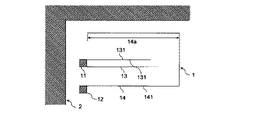
図2は、本発明の実施形態2に係わる車両用ガラスアンテナの車内側から見た正面図である。実施形態1の車両用ガラスアンテナとは、ループ状線条141の開放端部が、ボディフランジとの近接部14aを形成し、ボディフランジの端縁2と近接し、容量結合している点が異なっている。
<
FIG. 2 is a front view of a glass antenna for a vehicle according to
実施形態2の車両用ガラスアンテナは、このようにボディフランジとの近接部14aを形成することにより、所望の帯域において、所望のアンテナ感度を得やすくすることができる。
The glass antenna for a vehicle according to the second embodiment can easily obtain a desired antenna sensitivity in a desired band by forming the
<実施形態3>
図3は、本発明の実施形態3に係わる車両用ガラスアンテナの車内側から見た正面図である。実施形態2の車両用ガラスアンテナとは、アース側給電点12が、芯線側給電点11に対して上側に離隔して配設されており、ループ状線条141のアース側給電点12に接続している側の端部が、ボディフランジとの近接部14aを形成し、ボディフランジの端縁2と近接し、容量結合している点が異なっている。このような構成であっても、ボディフランジとの近接部14aを形成することにより、所望の帯域において、所望のアンテナ感度を得やすくすることができる。
<
FIG. 3 is a front view of a glass antenna for a vehicle according to
<実施形態4>
図4は、本発明の実施形態4に係わる車両用ガラスアンテナの車内側から見た正面図である。実施形態2の車両用ガラスアンテナとは、芯線側給電点11とアース側給電点12とが横に離隔して配設されている点と、芯線側エレメント13が、L字型の線条となっており、前記線条が、芯線側給電点11にその一端が接続されて下方に延伸される垂直線条132と、垂直線条132の下端に接続され、右方に延伸される水平線条131とから構成されている点が異なっている。本発明の車両用ガラスアンテナは、このような構成であっても、所望の帯域において、所望のアンテナ感度を容易に得ることができる。
<Embodiment 4>
FIG. 4 is a front view of a glass antenna for a vehicle according to Embodiment 4 of the present invention viewed from the inside of the vehicle. The glass antenna for a vehicle according to the second embodiment includes a point where the core-
<実施形態5>
図5は、本発明の実施形態5に係わる車両用ガラスアンテナの車内側から見た正面図である。実施形態2の車両用ガラスアンテナとは、ループ状線条141の先端部が上側に折り返されており、ループ状線条の折り返し部141aが形成されている点と、さらに、前記ループ状線条の折り返し部141aの先端部が、ボディフランジの端縁2と近接しボディフランジとの近接部14aを形成し、容量結合している点が異なっている。
<
FIG. 5 is a front view of a glass antenna for a vehicle according to
本発明の車両用ガラスアンテナは、このようにループ状線条141の先端部を折り返すことによって、所望の帯域において所望のアンテナ感度が得られるように前記ループ状線条の長さを保ちつつ、ループ状線条141によって囲まれる面積を小さくすることができる。また、車両のボディフランジの端縁2にループ線条の折り返し部141aの先端部を近接させて、ボディフランジとの近接部14aを形成することによって、ボディフランジとの近接部14aの長さの調整やボディフランジの端縁2との間隔の調整が容易になるため、所望の帯域での所望のアンテナ感度を得るためのアンテナチューニングがより容易になる。
The glass antenna for a vehicle of the present invention keeps the length of the loop-shaped filaments so that a desired antenna sensitivity can be obtained in a desired band by folding the tip of the loop-shaped
<実施形態6>
図6は、本発明の実施形態6に係わる車両用ガラスアンテナの車内側から見た正面図である。実施形態2の車両用ガラスアンテナとは、芯線側エレメント13が、2本の水平線条131が、それぞれの一端が芯線側給電点11に接続され、同じ方向に延伸されている点が異なっている。この2本の水平線条の長さは、所望の帯域において、所望のアンテナ感度が得られるように、同じ長さにしてもよいし、異なる長さにしてもよい。
<Embodiment 6>
FIG. 6 is a front view of a glass antenna for a vehicle according to Embodiment 6 of the present invention as viewed from the inside of the vehicle. The glass antenna for a vehicle according to the second embodiment is different from the glass antenna for a vehicle in that the core
また、芯線側エレメント13が、複数の線条で構成される場合、それぞれの線条の位置関係は、実施形態4のように水平線条131と垂直線条132の一端同士をつなぐ形状や、実施形態6のように芯線側給電点に、複数の線条のそれぞれの一端が接続され、同じ方向に延伸されるという形状にとらわれる必要はない。例えば、2本の線条から芯線側エレメントが構成される場合に、一本の線条の一端は芯線側給電点11に接続され、もう一本の線条の一端は、芯線側給電点11に接続されている前記線条の途中部に接続されるようにしても構わない。
Moreover, when the core
<実施形態7>
図7は、本発明の実施形態7に係わる車両用ガラスアンテナの車内側から見た正面図である。実施形態2の車両用ガラスアンテナとは、ループ状線条141が、矩形状ではない点が異なっている。本発明の車両用ガラスアンテナは、このように矩形状だけではなく、芯線側エレメント13が、ループ状線条141によって囲まれるように形成されていればその形状は問わない。
<Embodiment 7>
FIG. 7 is a front view of a glass antenna for a vehicle according to Embodiment 7 of the present invention as viewed from the inside of the vehicle. It differs from the glass antenna for vehicles of
<実施形態8>
図8は、本発明の実施形態8に係わる車両用ガラスアンテナの車内側から見た正面図である。実施形態7の車両用ガラスアンテナとは、ループ状線条141に、補助エレメントとして、補助線条142の一端が接続されている点が異なっている。このように補助線条142をループ状線条141に接続することによって、本発明の車両用ガラスアンテナの入力インピーダンスを、本発明の車両用ガラスアンテナに接続される同軸ケーブルの特性インピーダンスに合うように調整することができるため、補助線条142は、所望の帯域において所望のアンテナ感度を得るために役立てることができる。
<Eighth embodiment>
FIG. 8: is the front view seen from the vehicle inner side of the glass antenna for
<実施形態9>
図9は、本発明の実施形態9に係わる車両用ガラスアンテナの車内側から見た正面図である。実施形態8の車両用ガラスアンテナとは、補助エレメントが、無給電線条15となっており、ループ状線条141に、無給電線条15が近接し、ループ状線条の補助エレメントとの近接部14bが形成され、ループ状線条141が、無給電線条との近接部14bにおいて、無給電線条15と近接し容量結合している点が異なっている。補助エレメントをこのような無給電線条15で構成しても、所望の帯域において所望のアンテナ感度を得るために役立てることができる。
<Ninth Embodiment>
FIG. 9: is the front view seen from the vehicle inside of the glass antenna for vehicles concerning Embodiment 9 of this invention. In the glass antenna for a vehicle according to the eighth embodiment, the auxiliary element is the
<実施形態10>
図10は、本発明の実施形態10に係わる車両用ガラスアンテナの車内側から見た正面図である。実施形態8の車両用ガラスアンテナとは、ループ状線条141の先端部が折り返されている点と、補助エレメントとして、補助線条142に加えて、FM第2アンテナ3を構成するFM第2アンテナのエレメント32が使用されている点が異なっている。
<
FIG. 10: is the front view seen from the vehicle inside of the glass antenna for
そして、ループ状線条141が、FM第2アンテナのエレメント32の一部に近接しており、FM第2アンテナとの近接部14cが形成され、容量結合している。補助エレメントとして、このような本発明の車両用ガラスアンテナと別用途のアンテナを構成するエレメントを用いても、所望の帯域において所望のアンテナ感度を得るために役立てることができる。
The loop-shaped
<本発明の車両用ガラスアンテナと受信機との接続について>
本発明の車両用ガラスアンテナは、受信機まで前記車両用ガラスアンテナで受信した信号を伝送するための給電線として同軸線を用いている。前記同軸線の先端には、図示されていない給電端子を接続しており、その給電端子を本発明の車両用ガラスアンテナの芯線側給電点11及びアース側給電点12にはんだ付けしている。前記給電端子の芯線側には前記同軸線の芯線を接続しており、前記給電端子の接地側には、前記同軸線の外皮導体を接続している。
<Connection between Glass Antenna for Vehicle of the Present Invention and Receiver>
The vehicular glass antenna of the present invention uses a coaxial line as a feed line for transmitting a signal received by the vehicular glass antenna to a receiver. A feeding terminal (not shown) is connected to the tip of the coaxial line, and the feeding terminal is soldered to the core-
<本発明の車両用ガラスアンテナの形成方法について>
本発明の車両用ガラスアンテナは、リアガラスのデフォッガを形成するのと同じ一般的な導電性セラミックペーストを用いることができ、デフォッガと同じ方法で印刷し、加熱炉によって焼付けることができる。
<About the formation method of the glass antenna for vehicles of this invention>
The glass antenna for a vehicle of the present invention can use the same general conductive ceramic paste as that for forming a rear glass defogger, and can be printed by the same method as the defogger and baked in a heating furnace.
図10に示される本発明の実施形態10の車両用ガラスアンテナ1を、図11のようにリアガラス5のデフォッガ6上部のFM第1アンテナ4と、FM第2アンテナ3とに挟まれた余白部に配設した。さらに、DABのバンド3帯の周波数帯域である174〜240MHzにおいて好適となるように各構成要素の寸法、位置関係及びFM第2アンテナ3との位置関係を調整した。そして、リアガラス5を車両に取り付けて、実施形態10の車両用ガラスアンテナのDABのバンド3帯の周波数帯域でのアンテナ性能の測定を行った。
A blank portion sandwiched between the FM first antenna 4 and the FM
<リアガラス上での各アンテナの位置関係>
図11は、車内側から見たときのリアガラス5を示した図であり、リアガラス5には、デフォッガ6と、FM第1アンテナ4、FM第2アンテナ3及びDABのバンド3帯受信用に調整された本発明の車両用ガラスアンテナ1を配設した。
<Positional relationship of each antenna on the rear glass>
FIG. 11 is a view showing the
デフォッガ6は、リアガラス5の左右両端に、それぞれ左右両側辺に沿うように一対のバスバ62を配設し、一対のバスバ62の間は、複数の加熱線条61を、水平方向に配設し、それぞれの加熱線条61の両端をバスバ62に接続した。さらに、リアガラス5の左右方向の中心線dに沿って、最上部の加熱線条61から、最下部の加熱線条61まで直交線条63が配設し、直交線条63と重なる全ての加熱線条61と接続した。
The defogger 6 is provided with a pair of
FM第1アンテナ4は、リアガラス5のデフォッガ6上部に配設した。FM第1アンテナ4は、デフォッガ6上部のリアガラス5の右側端部にFM第1アンテナの給電点41を配設しており、FM第1アンテナの給電点41から、FM第1アンテナのエレメント42を延伸し、リアガラス5のデフォッガ6上部の左側に余白部が形成されるような構成とした。
The FM first antenna 4 was disposed on the upper portion of the defogger 6 of the
FM第2アンテナ3は、リアガラス5のデフォッガ6上部の左側のFM第1アンテナのエレメント42が配設されていない余白部に配設した。FM第2アンテナ3は、デフォッガ6上部のリアガラス5の右側辺部にFM第2アンテナの給電点31を配設しており、FM第2アンテナの給電点31からFM第2アンテナのエレメント32を延伸した。
The FM
FM第2アンテナのエレメント32を構成する線条は、その一端をFM第2アンテナの給電点31に接続し、リアガラス5の右方向に延伸し、途中で折り返し、折り返し部を形成する構成とした。さらに、FM第2アンテナのエレメント32は、FM第2アンテナの給電点31から、前記線条の折り返し部分にかけて、前記線条に平行になるように1本の線条を接続し、2重線を構成した。
The filament constituting the
本発明の車両用ガラスアンテナ1は、リアガラス5のデフォッガ6上部の左側のFM第1アンテナのエレメント42が配設されていない余白部で、FM第2アンテナ3の上部に位置するように配設した。
The
本発明の車両用ガラスアンテナ1は、芯線側給電点11とアース側給電点12とを、リアガラス5の左側側辺部に沿うように上下に離隔して配設した。そして、芯線側給電点11は、アース側給電点12よりも上側に配設した。
In the
アース側エレメント14のループ状線条141は、その一端がアース側給電点12に接続しており、その線条の下側は、リアガラス5の右側に延伸し、FM第2アンテナのエレメント32を構成する線条の折り返し部に近接し、ループ状線条とFM第2アンテナとの近接部14cを形成して、容量結合させた。このような構成であるため、ループ状線条141の下部は、FM第2アンテナのエレメント32を構成する線条の折り返し部に一定の間隔で近接させるために、水平に右方向に延伸したのち、一旦、下側に屈曲させてから、上側に折り返す構成とした。
One end of the loop-shaped
また、アース側エレメントの補助線条142は、ループ状線条141の下部で、上側に折り返される屈曲点に、その一端が接続し、右側に水平に延伸した。さらにまた、ループ状線条の折り返し部141aが、リアガラス5を車両に取り付けたときに、ボディフランジの端縁2に近接するように配設した。
Further, the
<本発明の車両用ガラスアンテナとFM第2アンテナの寸法、両アンテナ間の間隔>
図10に示した符号を用いて以下に寸法を記す。
<Dimensions of Glass Antenna for Vehicle of the Present Invention and FM Second Antenna, Distance Between Both Antennas>
The dimensions are described below using the reference numerals shown in FIG.
[本発明の車両用ガラスアンテナの寸法]
芯線側給電点及びアース側給電点の寸法=10mm×10mm
芯線側給電点11とアース側給電点との間隔1k=30mm
芯線側エレメントの水平線条131の長さ1a=110mm
2本の芯線側エレメントの水平線条131の間隔1b=15mm
ループ状線条141の全長=670mm
ループ状線条141の1c部分の長さ=175mm
ループ状線条141の1d部分の長さ=40mm
ループ状線条141の1e部分の長さ=45mm
ループ状線条141の1f部分の長さ=115mm
ループ状線条141の1g部分の長さ=220mm
ループ状線条の折り返し部141aの全長=75mm
ループ状線条の折り返し部141aの1h部分の長さ=15mm
ループ状線条の折り返し部141aの1i部分の長さ=60mm
アース側エレメントの補助線条142=110mm
ループ状エレメントとボディフランジの端縁との近接部14a=60mm
ループ状エレメントとFM第2アンテナとの近接部14c=205mm
ループ状線条141の全長は、DABのバンド3帯の周波数帯域の中心周波数(207MHz)の波長をλとし、本発明のガラスアンテナを配設したガラスの波長短縮率α=0.7としたときに、約0.7αと表すことができる。
[Dimensions of Glass Antenna for Vehicle of the Present Invention]
Dimensions of core wire side feed point and ground side feed point = 10 mm × 10 mm
Interval 1k = 30mm between core wire
Length 1a = 110mm of
Interval 1b = 15mm between
Total length of the loop-shaped
The length of the 1c portion of the looped
The length of the 1d portion of the looped
The length of the 1e portion of the loop-shaped
The length of the 1f portion of the looped
Length of 1 g part of loop-shaped
Overall length of the loop-shaped line-folded
The length of the 1h portion of the loop-shaped line-folded
The length of the 1i portion of the loop-shaped line-folded
The total length of the loop-shaped
[FM第2アンテナの寸法]
FM第2アンテナの3a部分の長さ=170mm
FM第2アンテナの3b部分の長さ=25mm
FM第2アンテナの3c部分の長さ=160mm
FM第2アンテナの3d部分の間隔=10mm。
[Dimension of FM second antenna]
FM second antenna 3a length = 170 mm
FM second antenna 3b length = 25mm
Length of part 3c of FM second antenna = 160 mm
The distance between the 3d portions of the FM second antenna = 10 mm.
[本発明の車両用ガラスアンテナとFM第2アンテナ、ボディフランジの端縁との間隔]
ループ状線条と折り返し部との間隔a=5mm
ループ状線条141の下部水平部とFM第2アンテナの折り返し部との間隔b=5mm
ループ状線条141の下部下側への屈曲部とFM第2アンテナの折り返し部との間隔c=5mm
アース側給電点12とFM第2アンテナの給電点31との間隔d=20mm。
[Gap between the vehicle glass antenna of the present invention, FM second antenna, and edge of body flange]
Spacing between looped filament and folded part a = 5 mm
Spacing b = 5 mm between the lower horizontal portion of the loop-shaped
The distance c = 5 mm between the lower bent portion of the loop-shaped
The distance d between the ground
<各アンテナの形成方法>
本発明の車両用ガラスアンテナ1も、FM第2アンテナ3も、FM第1アンテナ4も、リアガラスのデフォッガを形成するのと同じ一般的な導電性セラミックペーストを用いることができ、デフォッガと同じ方法で印刷し、加熱炉によって焼付けた。また、全てのアンテナを構成する各線条の幅は3mmとした。
<Method for forming each antenna>
The
<各アンテナの受信機との接続方法>
[FM第1アンテナ及びFM第2アンテナと受信機との接続方法]
FM第1アンテナ4は、FM第1アンテナの給電点41の近傍の車体上に設置された図示しないアンプにAV線によって接続され、前記アンプに受信機から延ばされている同軸線を接続した。同軸線の外皮側は、アンプを介して車体に接地させた。また、FM第2アンテナ3は、アンプには接続していない。そのため、FM第2アンテナ3は、FM第2アンテナの給電点31の近傍の車体上に図示しない接地点に、図示しない受信機から接地点までを図示しない同軸ケーブルで接続し、前記同軸ケーブルの外皮側は接地し、前記同軸ケーブルの芯線側は、図示しないAV線に接続し、FM第2アンテナの給電点31までを接続した。
<How to connect each antenna to the receiver>
[Connection method between FM first antenna and FM second antenna and receiver]
The FM first antenna 4 is connected to an amplifier (not shown) installed on the vehicle body in the vicinity of the
[本発明の車両用ガラスアンテナの受信機との接続方法]
本発明の車両用ガラスアンテナ1は、受信機まで前記アンテナで受信した信号を伝送するための給電線として同軸線を用いた。前記同軸線の先端には、図示されていない給電端子を接続し、その給電端子のアース側をアース側給電点12に、ホット側にはホット側給電点11を接続している。そして、前記給電端子と各給電点とははんだ付けによって接続している。また、前記給電端子のホット側には、前記同軸線の芯線を接続しており、前記給電端子のアース側には、前記同軸線の外皮導体を接続した。そして、前記同軸線のもう一方の先端を受信機と接続した。
[Method for Connecting Glass Antenna for Vehicle of the Present Invention to Receiver]
The
<本発明の車両用ガラスアンテナの測定結果>
図12は、本発明の車両用ガラスアンテナのDABのバンド3帯である174〜240MHzの周波数帯での各周波数におけるアンテナ感度の全方位での平均値を示したものである(以下、単にアンテナ感度と呼ぶことにする)。図12の横軸の単位は周波数であり、単位はMHzである。図12の縦軸は、アンテナ感度を示しており、一目盛は10dBである。
<Measurement result of glass antenna for vehicle of the present invention>
FIG. 12 shows the average value of the antenna sensitivity in all directions in the frequency band of 174 to 240 MHz, which is the
図12において、DABのバンド3帯である174〜240MHzの周波数帯において、一様に高いアンテナ感度が得られていることがわかる。
In FIG. 12, it can be seen that uniformly high antenna sensitivity is obtained in the frequency band of 174 to 240 MHz, which is the
図13に示される本発明の実施形態2の車両用ガラスアンテナ1を、図13のようにフロントガラス7の右側上部に配設した。さらに、DABのバンド3帯の周波数帯域である174〜240MHzにおいて好適となるように各構成要素の寸法、位置関係を調整した。そして、フロントガラス7を車両に取り付けて、実施形態2の車両用ガラスアンテナのDABのバンド3帯の周波数帯域でのアンテナ性能の測定を行った。
The
本発明の車両用ガラスアンテナ1は、受信機まで前記アンテナで受信した信号を伝送するための給電線として同軸線を用いた。前記同軸線の先端には、図示されていない給電端子を接続し、その給電端子のアース側をアース側給電点12に、ホット側にはホット側給電点11を接続している。そして、前記給電端子と各給電点とははんだ付けによって接続している。また、前記給電端子のホット側には、前記同軸線の芯線を接続しており、前記給電端子のアース側には、前記同軸線の外皮導体を接続した。そして、前記同軸線のもう一方の先端を受信機と接続した。そして、測定した結果、実施例1と同様にDABのバンド3帯である174〜240MHzの周波数帯において、一様に高いアンテナ感度が得られていることがわかった。
The
図14に示される本発明の実施形態1の車両用ガラスアンテナ1を、図14のようにサイドガラス8の左側辺部に配設した。さらに、DABのバンド3帯の周波数帯域である174〜240MHzにおいて好適となるように各構成要素の寸法、位置関係を調整した。そして、サイドガラス8を車両に取り付けて、実施形態1の車両用ガラスアンテナのDABのバンド3帯の周波数帯域でのアンテナ性能の測定を行った。
The
本発明の車両用ガラスアンテナ1は、受信機まで前記アンテナで受信した信号を伝送するための給電線として同軸線を用いた。前記同軸線の先端には、図示されていない給電端子を接続し、その給電端子のアース側をアース側給電点12に、ホット側にはホット側給電点11を接続している。そして、前記給電端子と各給電点とははんだ付けによって接続している。また、前記給電端子のホット側には、前記同軸線の芯線を接続しており、前記給電端子のアース側には、前記同軸線の外皮導体を接続した。そして、前記同軸線のもう一方の先端を受信機と接続した。そして、測定した結果、実施例1と同様にDABのバンド3帯である174〜240MHzの周波数帯において、一様に高いアンテナ感度が得られていることがわかった。
The
1 車両用ガラスアンテナ
11 芯線側給電点
12 アース側給電点
13 芯線側エレメント
131 芯線側エレメントの水平線条
132 芯線側エレメントの垂直線条
14 アース側エレメント
14a ボディフランジとの近接部
14b 無給電線条との近接部
14c FM第2アンテナとの近接部
141 ループ状線条
141a ループ状線条の折り返し部
142 アース側エレメントの補助線条
15 無給電エレメント
2 ボディフランジの端縁
3 FM第2アンテナ
31 FM第2アンテナの給電点
32 FM第2アンテナのエレメント
4 FM第1アンテナ
41 FM第1アンテナの給電点
42 FM第1アンテナのエレメント
5 リアガラス
6 デフォッガ
61 加熱線条
62 バスバ
63 直交線条
7 フロントガラス
8 サイドガラス
DESCRIPTION OF
Claims (4)
芯線側給電点(11)と、
前記芯線側給電点(11)と離隔されて設けられているアース側給電点(12)と、
前記芯線側給電点(11)に接続され、前記芯線側給電点(11)から遠ざかる方向に延伸される芯線側エレメント(13)と、
前記アース側給電点(12)に接続されるループ状線条(141)と、を備えており、
前記ループ状線条(141)は、前記芯線側給電点(11)及び前記アース側給電点(12)から遠ざかる方向に延伸され、屈曲させられることで、前記芯線側エレメント(13)を囲み、その先端が開放端となっており、
前記ループ状線条(141)の開放端が、ボディフランジとの近接部(14a)を形成し、ボディフランジの端縁(2)と近接し、容量結合していることを特徴とする車両用ガラスアンテナ。 A vehicle glass antenna disposed on a window glass of an automobile,
A core wire side feeding point (11);
An earth-side feeding point (12) provided separately from the core-side feeding point (11);
A core wire side element (13) connected to the core wire side feed point (11) and extending in a direction away from the core wire side feed point (11);
A loop-shaped filament (141) connected to the ground-side feeding point (12),
The loop-shaped filament (141) is extended and bent in a direction away from the core-side feeding point (11) and the ground-side feeding point (12), thereby enclosing the core-side element (13), Its tip is an open end ,
An open end of the loop-shaped filament (141) forms a proximity portion (14a) with a body flange, is close to an end edge (2) of the body flange, and is capacitively coupled . Glass antenna.
Priority Applications (3)
| Application Number | Priority Date | Filing Date | Title |
|---|---|---|---|
| JP2013076981A JP6094334B2 (en) | 2013-04-02 | 2013-04-02 | Glass antenna for vehicles |
| EP14161055.0A EP2787573B1 (en) | 2013-04-02 | 2014-03-21 | Vehicular glass antenna |
| AU2014201814A AU2014201814B2 (en) | 2013-04-02 | 2014-03-27 | Vehicular glass antenna |
Applications Claiming Priority (1)
| Application Number | Priority Date | Filing Date | Title |
|---|---|---|---|
| JP2013076981A JP6094334B2 (en) | 2013-04-02 | 2013-04-02 | Glass antenna for vehicles |
Publications (2)
| Publication Number | Publication Date |
|---|---|
| JP2014204190A JP2014204190A (en) | 2014-10-27 |
| JP6094334B2 true JP6094334B2 (en) | 2017-03-15 |
Family
ID=50389247
Family Applications (1)
| Application Number | Title | Priority Date | Filing Date |
|---|---|---|---|
| JP2013076981A Active JP6094334B2 (en) | 2013-04-02 | 2013-04-02 | Glass antenna for vehicles |
Country Status (3)
| Country | Link |
|---|---|
| EP (1) | EP2787573B1 (en) |
| JP (1) | JP6094334B2 (en) |
| AU (1) | AU2014201814B2 (en) |
Families Citing this family (8)
| Publication number | Priority date | Publication date | Assignee | Title |
|---|---|---|---|---|
| JP6527325B2 (en) * | 2014-12-08 | 2019-06-05 | 日本板硝子株式会社 | Vehicle rear quarter glass antenna |
| JP6812824B2 (en) * | 2017-02-14 | 2021-01-13 | Agc株式会社 | Vehicle window glass |
| JP7013824B2 (en) * | 2017-02-14 | 2022-02-15 | Agc株式会社 | Glass antennas and windowpanes for vehicles |
| JP6812825B2 (en) * | 2017-02-14 | 2021-01-13 | Agc株式会社 | Glass antennas and windowpanes for vehicles |
| US10573962B2 (en) * | 2017-02-14 | 2020-02-25 | AGC Inc. | Glass antenna and window glass for vehicle |
| JP6888423B2 (en) * | 2017-05-30 | 2021-06-16 | Agc株式会社 | Window glass with antenna |
| JP7480571B2 (en) | 2020-04-22 | 2024-05-10 | Agc株式会社 | Vehicle window glass |
| JP2023127240A (en) | 2022-03-01 | 2023-09-13 | Agc株式会社 | Window glass for vehicle |
Family Cites Families (5)
| Publication number | Priority date | Publication date | Assignee | Title |
|---|---|---|---|---|
| JP3565406B2 (en) * | 1998-11-16 | 2004-09-15 | セントラル硝子株式会社 | Glass antenna for vehicles |
| JP2005229140A (en) | 2003-03-19 | 2005-08-25 | Central Glass Co Ltd | Antenna for vehicle |
| JP5720308B2 (en) * | 2010-06-16 | 2015-05-20 | セントラル硝子株式会社 | Glass antenna for vehicles |
| JP2012029032A (en) * | 2010-07-23 | 2012-02-09 | Central Glass Co Ltd | Vehicle antenna |
| JP2013131889A (en) * | 2011-12-21 | 2013-07-04 | Central Glass Co Ltd | Vehicular glass antenna |
-
2013
- 2013-04-02 JP JP2013076981A patent/JP6094334B2/en active Active
-
2014
- 2014-03-21 EP EP14161055.0A patent/EP2787573B1/en active Active
- 2014-03-27 AU AU2014201814A patent/AU2014201814B2/en not_active Ceased
Also Published As
| Publication number | Publication date |
|---|---|
| AU2014201814A1 (en) | 2014-10-16 |
| JP2014204190A (en) | 2014-10-27 |
| AU2014201814B2 (en) | 2015-05-21 |
| EP2787573B1 (en) | 2016-11-30 |
| EP2787573A1 (en) | 2014-10-08 |
Similar Documents
| Publication | Publication Date | Title |
|---|---|---|
| JP6094334B2 (en) | Glass antenna for vehicles | |
| JP5720308B2 (en) | Glass antenna for vehicles | |
| JP5299276B2 (en) | High frequency glass antenna for automobile | |
| JP6221773B2 (en) | Glass antenna | |
| US9136583B2 (en) | Automotive window antenna | |
| JP4941171B2 (en) | Glass antenna for vehicles | |
| JP3974087B2 (en) | Glass antenna for vehicles | |
| JP6221779B2 (en) | Glass antenna | |
| JP4682967B2 (en) | High frequency glass antenna for automobile and window glass plate for automobile | |
| JP6123457B2 (en) | Glass antenna for automobile | |
| JP6390666B2 (en) | Glass antenna | |
| JP2009033687A (en) | Glass antenna for vehicle | |
| JP2012029032A (en) | Vehicle antenna | |
| JP5671971B2 (en) | Vehicle antenna | |
| JP6251476B2 (en) | Glass antenna for vehicles | |
| JP2012044254A (en) | Vehicle antenna | |
| JP5742509B2 (en) | Glass antenna for vehicles | |
| JP2009164678A (en) | Glass antenna for vehicle | |
| JP2016072910A (en) | Antenna and window pane | |
| JP2016058946A (en) | Glass antenna for vehicle | |
| JP6319407B2 (en) | Glass antenna for vehicles | |
| JP2010088057A (en) | Vehicle glass antenna | |
| JP2011146963A (en) | Glass antenna |
Legal Events
| Date | Code | Title | Description |
|---|---|---|---|
| A621 | Written request for application examination |
Free format text: JAPANESE INTERMEDIATE CODE: A621 Effective date: 20160121 |
|
| A977 | Report on retrieval |
Free format text: JAPANESE INTERMEDIATE CODE: A971007 Effective date: 20161012 |
|
| A131 | Notification of reasons for refusal |
Free format text: JAPANESE INTERMEDIATE CODE: A131 Effective date: 20161018 |
|
| A521 | Request for written amendment filed |
Free format text: JAPANESE INTERMEDIATE CODE: A523 Effective date: 20161130 |
|
| TRDD | Decision of grant or rejection written | ||
| A01 | Written decision to grant a patent or to grant a registration (utility model) |
Free format text: JAPANESE INTERMEDIATE CODE: A01 Effective date: 20170117 |
|
| A61 | First payment of annual fees (during grant procedure) |
Free format text: JAPANESE INTERMEDIATE CODE: A61 Effective date: 20170130 |
|
| R150 | Certificate of patent or registration of utility model |
Ref document number: 6094334 Country of ref document: JP Free format text: JAPANESE INTERMEDIATE CODE: R150 |
|
| R250 | Receipt of annual fees |
Free format text: JAPANESE INTERMEDIATE CODE: R250 |
|
| R250 | Receipt of annual fees |
Free format text: JAPANESE INTERMEDIATE CODE: R250 |
|
| R250 | Receipt of annual fees |
Free format text: JAPANESE INTERMEDIATE CODE: R250 |
|
| R250 | Receipt of annual fees |
Free format text: JAPANESE INTERMEDIATE CODE: R250 |
|
| S111 | Request for change of ownership or part of ownership |
Free format text: JAPANESE INTERMEDIATE CODE: R313111 |
|
| R350 | Written notification of registration of transfer |
Free format text: JAPANESE INTERMEDIATE CODE: R350 |
|
| R250 | Receipt of annual fees |
Free format text: JAPANESE INTERMEDIATE CODE: R250 |