EP2787425B1 - Détection optique de mouvements de flexion d'un affichage flexible - Google Patents
Détection optique de mouvements de flexion d'un affichage flexible Download PDFInfo
- Publication number
- EP2787425B1 EP2787425B1 EP14163274.5A EP14163274A EP2787425B1 EP 2787425 B1 EP2787425 B1 EP 2787425B1 EP 14163274 A EP14163274 A EP 14163274A EP 2787425 B1 EP2787425 B1 EP 2787425B1
- Authority
- EP
- European Patent Office
- Prior art keywords
- image
- images
- time
- sensor
- flexible display
- Prior art date
- Legal status (The legal status is an assumption and is not a legal conclusion. Google has not performed a legal analysis and makes no representation as to the accuracy of the status listed.)
- Active
Links
- 230000033001 locomotion Effects 0.000 title claims description 146
- 238000001514 detection method Methods 0.000 title claims description 41
- 238000005452 bending Methods 0.000 title claims description 28
- 230000003287 optical effect Effects 0.000 title 1
- 239000013598 vector Substances 0.000 claims description 128
- 238000000034 method Methods 0.000 claims description 24
- 230000008859 change Effects 0.000 claims description 17
- 238000004364 calculation method Methods 0.000 claims description 8
- 230000006870 function Effects 0.000 claims description 8
- 230000007613 environmental effect Effects 0.000 claims description 6
- 238000013507 mapping Methods 0.000 claims description 5
- 230000008569 process Effects 0.000 claims description 5
- 238000010586 diagram Methods 0.000 description 6
- 238000012545 processing Methods 0.000 description 4
- 230000009471 action Effects 0.000 description 2
- 238000005516 engineering process Methods 0.000 description 2
- 210000003128 head Anatomy 0.000 description 2
- 238000003384 imaging method Methods 0.000 description 2
- 238000005259 measurement Methods 0.000 description 2
- 230000000007 visual effect Effects 0.000 description 2
- 238000012935 Averaging Methods 0.000 description 1
- 230000001133 acceleration Effects 0.000 description 1
- 230000000052 comparative effect Effects 0.000 description 1
- 230000004069 differentiation Effects 0.000 description 1
- 230000000694 effects Effects 0.000 description 1
- 230000004313 glare Effects 0.000 description 1
- 230000003993 interaction Effects 0.000 description 1
- 230000031700 light absorption Effects 0.000 description 1
- 238000012417 linear regression Methods 0.000 description 1
- 230000004044 response Effects 0.000 description 1
- 238000000926 separation method Methods 0.000 description 1
Images


Classifications
-
- G—PHYSICS
- G06—COMPUTING; CALCULATING OR COUNTING
- G06F—ELECTRIC DIGITAL DATA PROCESSING
- G06F1/00—Details not covered by groups G06F3/00 - G06F13/00 and G06F21/00
- G06F1/16—Constructional details or arrangements
- G06F1/1613—Constructional details or arrangements for portable computers
- G06F1/1633—Constructional details or arrangements of portable computers not specific to the type of enclosures covered by groups G06F1/1615 - G06F1/1626
- G06F1/1637—Details related to the display arrangement, including those related to the mounting of the display in the housing
- G06F1/1652—Details related to the display arrangement, including those related to the mounting of the display in the housing the display being flexible, e.g. mimicking a sheet of paper, or rollable
-
- G—PHYSICS
- G06—COMPUTING; CALCULATING OR COUNTING
- G06F—ELECTRIC DIGITAL DATA PROCESSING
- G06F3/00—Input arrangements for transferring data to be processed into a form capable of being handled by the computer; Output arrangements for transferring data from processing unit to output unit, e.g. interface arrangements
- G06F3/01—Input arrangements or combined input and output arrangements for interaction between user and computer
- G06F3/017—Gesture based interaction, e.g. based on a set of recognized hand gestures
-
- G—PHYSICS
- G06—COMPUTING; CALCULATING OR COUNTING
- G06F—ELECTRIC DIGITAL DATA PROCESSING
- G06F3/00—Input arrangements for transferring data to be processed into a form capable of being handled by the computer; Output arrangements for transferring data from processing unit to output unit, e.g. interface arrangements
- G06F3/01—Input arrangements or combined input and output arrangements for interaction between user and computer
- G06F3/03—Arrangements for converting the position or the displacement of a member into a coded form
- G06F3/0304—Detection arrangements using opto-electronic means
-
- G—PHYSICS
- G06—COMPUTING; CALCULATING OR COUNTING
- G06F—ELECTRIC DIGITAL DATA PROCESSING
- G06F3/00—Input arrangements for transferring data to be processed into a form capable of being handled by the computer; Output arrangements for transferring data from processing unit to output unit, e.g. interface arrangements
- G06F3/01—Input arrangements or combined input and output arrangements for interaction between user and computer
- G06F3/048—Interaction techniques based on graphical user interfaces [GUI]
- G06F3/0487—Interaction techniques based on graphical user interfaces [GUI] using specific features provided by the input device, e.g. functions controlled by the rotation of a mouse with dual sensing arrangements, or of the nature of the input device, e.g. tap gestures based on pressure sensed by a digitiser
-
- H—ELECTRICITY
- H04—ELECTRIC COMMUNICATION TECHNIQUE
- H04M—TELEPHONIC COMMUNICATION
- H04M1/00—Substation equipment, e.g. for use by subscribers
- H04M1/02—Constructional features of telephone sets
- H04M1/0202—Portable telephone sets, e.g. cordless phones, mobile phones or bar type handsets
- H04M1/026—Details of the structure or mounting of specific components
- H04M1/0266—Details of the structure or mounting of specific components for a display module assembly
- H04M1/0268—Details of the structure or mounting of specific components for a display module assembly including a flexible display panel
- H04M1/0269—Details of the structure or mounting of specific components for a display module assembly including a flexible display panel mounted in a fixed curved configuration, e.g. display curved around the edges of the telephone housing
-
- G—PHYSICS
- G06—COMPUTING; CALCULATING OR COUNTING
- G06F—ELECTRIC DIGITAL DATA PROCESSING
- G06F2203/00—Indexing scheme relating to G06F3/00 - G06F3/048
- G06F2203/041—Indexing scheme relating to G06F3/041 - G06F3/045
- G06F2203/04102—Flexible digitiser, i.e. constructional details for allowing the whole digitising part of a device to be flexed or rolled like a sheet of paper
-
- G—PHYSICS
- G06—COMPUTING; CALCULATING OR COUNTING
- G06T—IMAGE DATA PROCESSING OR GENERATION, IN GENERAL
- G06T7/00—Image analysis
- G06T7/10—Segmentation; Edge detection
- G06T7/11—Region-based segmentation
-
- G—PHYSICS
- G06—COMPUTING; CALCULATING OR COUNTING
- G06T—IMAGE DATA PROCESSING OR GENERATION, IN GENERAL
- G06T7/00—Image analysis
- G06T7/20—Analysis of motion
- G06T7/292—Multi-camera tracking
-
- G—PHYSICS
- G06—COMPUTING; CALCULATING OR COUNTING
- G06T—IMAGE DATA PROCESSING OR GENERATION, IN GENERAL
- G06T7/00—Image analysis
- G06T7/30—Determination of transform parameters for the alignment of images, i.e. image registration
- G06T7/33—Determination of transform parameters for the alignment of images, i.e. image registration using feature-based methods
-
- H—ELECTRICITY
- H04—ELECTRIC COMMUNICATION TECHNIQUE
- H04N—PICTORIAL COMMUNICATION, e.g. TELEVISION
- H04N23/00—Cameras or camera modules comprising electronic image sensors; Control thereof
- H04N23/60—Control of cameras or camera modules
- H04N23/68—Control of cameras or camera modules for stable pick-up of the scene, e.g. compensating for camera body vibrations
Definitions
- An aspect of embodiments of the present invention relates generally to the detection of the bending motions of a flexible display, and the measurement of the bend angles over time.
- Flexible displays such as flexible organic light emitting diode displays
- the new form-factor of flexible displays creates a number of new usage cases and applications, such as twist-based user inputs.
- information on the amount of bending could be utilized for life-time stress diagnostics of the flexible display.
- US2012/235893 discloses systems, methods and apparatus for displaying visual information on a bendable or flexible display device in response to both a deformation data of the display device and viewer position data.
- the deformation data such as bend or contour of display device may be determined from the processing of images of the display device captured from one or more cameras.
- the viewer position data is obtained from successive images of the viewer's head, face and/or eyes and identification of landmarks on these viewer features.
- the present invention provides a detection device of a flexible display as claimed in claims 1 to 5 and a method of detecting a bending of a flexible display as claimed in claims 6 to 8.
- a device may identify distinguishing factors between a reference condition of the flexible display (e.g., the reference condition of the flexible display being when the flexible display is flat and unbent) and a dynamic condition of the flexible display (e.g., when the flexible display is bent or curved).
- a reference condition of the flexible display e.g., the reference condition of the flexible display being when the flexible display is flat and unbent
- a dynamic condition of the flexible display e.g., when the flexible display is bent or curved.
- the reference condition and the dynamic condition may be any two conditions where the flexible display is differently bent, including a situation where one of the two conditions is unbent.
- Possible factors that may be considered to distinguish the reference condition from the dynamic condition may include, for example, mechanical stress experienced by components of the flexibly display, a surface pressure of the flexible display, detection of motion using a gyroscope, measurement of acceleration of one or more portions of the flexible display, and/or changes in light absorption or light perceived by the flexible display.
- the described technology provides a flexible display capable of measuring a degree of bending of the display.
- Embodiments of the present invention utilize multiple image sensors as part of a detection device embedded in or near a flexible display. As the flexible display is bent, the lines of sight of the image sensors change. By using the image sensors to capture images of the environmental surroundings, and by comparing distinctive features of the images over time using the detection device's processor/computing devices, a system of an embodiment of the present invention can measure the angular changes in the lines-of-sight of the image sensors, and can thereafter extrapolate the changing shape of the flexible display.
- a detection device of a flexible display including image sensors "A" and “B” (or first and second image sensors) configured to capture images, a processor configured to process the images captured by the image sensors, and a memory having instructions stored therein that, when executed by the processor, result in calculation of a bend angle of the flexible display by comparing the images.
- the detection device further includes a buffer configured to store the images captured by the image sensors, and configured to provide first-in-time images of the images captured at a first time, and second-in-time images of the images captured at a second time after the first time, to the processor, and the processor may preferably be further configured to compare the first-in-time images to the second-in-time images to calculate the bend angle by executing the instructions in the memory.
- the processor is configured to compare the first-in-time images to the second-in-time images by locating a distinctive feature commonly found in each of an image-sensor-A image of the first-in-time images and an image-sensor-A image of the second-in-time images, both of which being captured by the image sensor "A", and in each of an image-sensor-B image of the first-in-time images and an image-sensor-B image of the second-in-time images, both of which being captured by the image sensor "B”, marking a set of second coordinates of the distinctive feature for each of the second-in-time images, marking a set of first coordinates of the distinctive feature for each of the first-in-time images, calculating a first vector corresponding to a first distance and direction from the set of first coordinates of the image-sensor-A images to the set of second coordinates of the image-sensor-A images, and calculating a second vector corresponding to a second distance and direction from the set of first coordinates of the image-sensor-B images to the set of second coordinate
- Each of the coordinates may preferably correspond to an X-Y coordinate system.
- the processor may preferably be configured to compare the first-in-time images to the second-in-time images by locating a plurality of distinctive features commonly found in each of an image-sensor-A image of the first-in-time images and an image-sensor-A image of the second-in-time images, both of which being captured by the image sensor "A", and in each of an image-sensor-B image of the first-in-time images and an image-sensor-B image of the second-in-time images, both of which being captured by the image sensor "B", marking a set of second coordinates for each of the distinctive features in each of the second-in-time images, marking a set of first coordinates for each of the distinctive features in each of the first-in-time images, for each of the distinctive features of the image-sensor-A images, calculating a first-image-sensor motion vector corresponding to a first distance and direction from one of the sets of first coordinates of the image-sensor-A images to a corresponding set of second coordinates of the image-sensor-A images, for each
- the processor is configured to calculate a first-image-sensor minimum mean-square error (MMSE) motion vector with a minimum mean-square error corresponding to a quadratic best-fit of the first-image-sensor motion vectors, and calculating a second-image-sensor MMSE motion vector with a minimum mean-square error corresponding to a quadratic best-fit of the second-image-sensor motion vectors.
- MMSE first-image-sensor minimum mean-square error
- the detection device further includes an arithmetic unit that is configured to receive the first-image-sensor MMSE motion vector and the second-image-sensor MMSE motion vector, calculate an arithmetic average of the first-image-sensor MMSE motion vector and the second-image-sensor MMSE motion vector, subtract the arithmetic average from the first-image-sensor MMSE motion vector to generate a first-image-sensor differential motion vector, and subtract the arithmetic average from the second-image-sensor MMSE motion vector to generate a second-image-sensor differential motion vector.
- an arithmetic unit that is configured to receive the first-image-sensor MMSE motion vector and the second-image-sensor MMSE motion vector, calculate an arithmetic average of the first-image-sensor MMSE motion vector and the second-image-sensor MMSE motion vector, subtract the arithmetic average from the first-image-sensor MMSE motion vector to generate a first-image-sensor differential motion vector, and subtract the arithmetic average
- Generating the differential motion vectors may negate common movement of the image sensors with respect to an environmental area corresponding to the distinctive features.
- a common movement may include, for example, a lateral movement of the flexible display.
- the detection device may preferably further include a geometric unit configured to receive the differential motion vectors from the arithmetic unit, measure a number of pixels corresponding to a length of each of the differential motion vectors, convert the measured numbers of pixels into corresponding angles of deflection of a line-of sight of each of the image sensors with respect to a front-surface normal of the flexible display, and map the angles of deflection as a function of time.
- the geometric unit may also calculate the projection of the angles of deflection onto the front-surface plane of the flexible display in obtaining the angles of bending along the X-axis and the Y-axis of the flexible display as a function of time.
- the instructions stored in the memory when executed by the processor, may preferably cause the processor to process information as a result of the mapped angles, and the angles may correspond to X angles measured with respect to an X-axis and Y angles measured with respect to a Y-axis.
- the image sensors may preferably be on a periphery of a flexible display.
- a detection device including one or more image sensors configured to capture images, wherein the detection device is configured to detect bending or movement of the flexible display by analyzing the images captured by the one or more image sensors.
- the detection device may preferably be configured to calculate a degree of the detected bending by storing first-in-time images of the images captured at a first time and by storing second-in-time images of the images captured at a second time after the first time, and comparing the first-in-time images to respective ones of the second-in-time images captured by a same one of the image sensors to determine an angle that the one or more of the image sensors has moved with respect to a reference point.
- a method of detecting a bending of a flexible display including capturing a plurality of first-in-time images at a first time using a plurality of image sensors, capturing a plurality of second-in-time images at a second time using the plurality of image sensors, the second time being after the first time, and comparing the first-in-time images to the second-in-time images of corresponding ones of the image sensors.
- Comparing the first-in-time images to the second-in-time images includes executing instructions stored in a memory using a processor.
- the method further includes determining an angle corresponding to a change in a line-of-sight of one of the image sensors relative to a reference point of the flexible display from the first time to the second time according to the comparing of the first-in-time images to the second-in-time images, and calculating a bend angle of the flexible display corresponding to the change in the line-of-sight.
- the method may preferably further include mapping a plurality of calculated bend angles over time to determine lifetime stress diagnostics.
- Comparing the first-in-time images to the second-in-time images includes locating one or more distinctive features commonly found in the first-in-time images and the second-in-time images, marking a set of second coordinates for each of the one or more distinctive features in the second-in-time images, marking a set of first coordinates for each of the one or more distinctive features in the first-in-time images, and calculating, for each of the distinctive features of the images of each of the image sensors, a motion vector corresponding to a distance between each set of the first coordinates and a respective set of the second coordinates.
- a plurality of motion vectors is calculated, and comparing the first-in-time images to the second-in-time images further includes calculating, for each of the image sensors, a minimum mean-square error (MMSE) motion vector with a minimum mean-square error representing a quadratic best-fit of the motion vectors.
- MMSE minimum mean-square error
- Comparing the first-in-time images to the second-in-time images further includes calculating an arithmetic average of all of the MMSE motion vectors, and subtracting the arithmetic average from each of the MMSE motion vectors to generate a differential motion vector for each of the image sensors, thereby negating common movement of the image sensors.
- the method may preferably further include calculating one or more angles of deflection in the lines-of-sight of the image sensors with respect to the front-surface normal of the flexible display by measuring a number of pixels in one or more axes corresponding to a length of each of the differential motion vectors, converting the numbers of pixels in the one or more axes into the one or more angles of deflection based on the number of pixels per degree of field of view of each of the image sensors, and mapping the angles of deflection as a function of time.
- the method may preferably also calculate the projection of the angles of deflection onto the front-surface plane of the flexible display in obtaining the angles of bending along the X-axis and the Y-axis of the flexible display as a function of time.
- embodiments of the present invention can measure the amount of bending along the X-axis and the Y-axis (e.g., X-dimensional bending and Y-dimensional bending) of the flexible display.
- first element when a first element is described as being coupled to a second element, the first element may be directly coupled to the second element, or may be indirectly coupled to the second element via one or more other elements. Also, some of the elements that are not essential to the complete understanding of the invention are omitted for clarity. Also, like reference numerals refer to like elements throughout.
- a detection device in a flexible display can calculate or estimate a degree to which the flexible display is bent, including in which direction the flexible display is bent, by comparing a reference condition to a dynamic condition.
- Embodiments of the present invention distinguish the reference condition from the dynamic condition by imaging environmental surroundings.
- embodiments of the present invention visually detect the environment near the flexible display (e.g., environmental surroundings) while the flexible display is in a first condition (e.g. the reference condition), then visually detect the environment near the flexible display during a second condition subsequent of the first condition (e.g. the dynamic condition), and then compare the results of the different detections to calculate an amount of bending along the X-axis and the Y-axis of the flexible display.
- the visual detection of the environment may preferably be performed by detecting distinctive features of the environment that are captured by image sensors.
- the information regarding the degree of bending can be used to cause the detection device to take an action.
- the detection device can adjust the brightness of the display to counteract glare.
- the light emitting elements of the flexible display may, on average, degrade such that a different amount of electrical current may be required to cause a degraded pixel to emit light of a same brightness of a non-degraded pixel.
- compensation schemes can be introduced to compensate for the stressed areas (e.g., by providing a larger electrical current to areas of the flexible display expected to have pixels that are degraded to a higher degree). Accordingly, the detection device according to embodiments of the present invention allows for lifetime stress diagnostics.
- motion-based, or twist-based commands can be measured by the detection device of the present embodiments, which can allow a user to interact with the information provided on the flexible display by using such commands. Such interaction may include advancing a page in an electronic book or article, going back to a previous webpage, or various user commands corresponding to a video game shown on the flexible display.
- embodiments of the present invention can measure the location, degree, amount, and/or direction of bending of the flexible display by imaging the environmental surroundings.
- FIG. 1 is a block diagram for depicting various components of the detection device of a flexible display, according to an embodiment of the present invention.
- the detection device may reside in the flexible display, and may or may not be integrated with the various circuitry and/or internal components of the flexible display.
- the detection device 11 of the present embodiment contains the following components:
- the processor 19 is listed separately from the arithmetic unit 26 and the geometric unit 28, in other embodiments of the present invention, the arithmetic unit and the geometric unit may preferably be considered as part of, or as subunits of, the processor. Furthermore, the processor and other various components of the detection device 11 of embodiments of the present invention may operate by using a memory having instructions, or software code, that are executed by the processor, the arithmetic unit, the geometric unit, etc.
- angles of deflection represent the bending of the flexible display 10 with respect to the lines-of-sight of the image sensors 12. Accordingly, with a sufficient number of image sensors 12, and with a sufficient number of adequately captured images 14, embodiments of the present invention can measure or estimate the changing shape of the flexible display 10 over time.
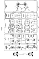
- FIG. 2a is a conceptual diagram representing a flexible display 10 shown in a flat, unbent state, wherein images of a subject/environment are detected by corresponding image sensors of the detection device 11, according to an embodiment of the present invention.
- FIG. 2b is a conceptual diagram representing the flexible display 10 shown in curved/bent state, wherein images of the subject/environment are detected by the corresponding image sensors of the detection device 11, according to the embodiment shown in FIG. 2a .
- the flat, unbent state of the flexible display of the present embodiment will be referred to as a reference condition
- the bent state of the flexible display of the present invention will be referred to as a dynamic condition.
- the angles of deflection e.g., angles ⁇ Ay1 , ⁇ Ay2 , ⁇ By1 , and ⁇ By2 , shown in FIG. 3
- the angles of deflection are formed between the respective lines-of-sight of the image sensors 12 and the front-surface normal 16 of the unbent flexible display 10, such that the angles of deflection are approximately zero degrees when the flexible display 10 is in the flat unbent state.
- the flexible display 10 in the flat state will provide an example of the image sensors 12 capturing the first-in-time images 14t0. Furthermore, the image sensors 12 in FIGS. 2a and 2b will be located on the side of the flexible display 10 closest to the subject 17 (e.g., the image sensors 12 will be directly on the other side of the points referenced by the various versions of the reference character 12).
- the various images 14 of the subject 17 captured by the image sensors 12 will be relatively the same. That is, the location of the image of the subject in the frame of each of the images 14 will be relatively the same for each of the image sensors 12. Furthermore, the one or more distinctive features 18 (e.g., the eyes of the subject 17) will be located at approximately the same X and Y coordinates 20 corresponding to each of images 14 captured by the image sensors 12.
- the present embodiment of the invention uses an X-Y coordinate system for mapping the coordinates 20
- other embodiments of the present invention may use other coordinate systems, such as, for example, a Cartesian coordinate system, or a polar coordinate system.
- the flexible display 10 includes twelve image sensors 12. Accordingly, twelve images 14 are shown in an arrangement similar to that of the twelve image sensors 12 to provide a representation of each of the images 14 captured by each of the image sensors 12. It should be noted that although the present embodiment depicts twelve image sensors 12, other embodiments of the present invention may include as few as one image sensor or more than twelve image sensors, for example from two to 20 image sensors. Furthermore, although the present embodiment depicts a rectangular flexible display 10, the shape of the flexible display 10 is not so limited, and the flexible display of other embodiments may preferably have other suitable shapes.
- the image sensors 12 are shown to be at, or near, the perimeter of the flexible display 10.
- other embodiments of the present invention may include image sensors 12 that are differently located (e.g., the image sensors 12 may be in the screen of the flexible display 10), by having the image sensors 12 at/near the perimeter, bends in the flexible display 10 will result in greater changes of the line-of-sight of the image sensors 12 due to their distance from the center of the flexible display 10, thereby allowing for more accurate calculation of the bend angles of the flexible display 10. That is, the greater the spatial separation between adjacent ones of the image sensors 12, the greater the resolution of the bend angle detection.
- the subject 17 contains the distinctive feature(s) 18 found in each of the first-in-time images 14t0 and in each of the second-in-time images 14t1, and the locations of the distinctive feature(s) 18 will be compared for purposes of determining the relative change of the bend angle(s) ⁇ (e.g., angles of deflection ⁇ Ay1 , ⁇ Ay2 , ⁇ By1 , and ⁇ By2 along the Y-axis of the flexible display, shown in FIG. 3 ).
- the bend angle(s) ⁇ e.g., angles of deflection ⁇ Ay1 , ⁇ Ay2 , ⁇ By1 , and ⁇ By2 along the Y-axis of the flexible display, shown in FIG. 3 ).
- more accurate calculation of the bend angles can be achieved if the distinctive feature(s) 18 are present in each of the images 14 for each of the image sensors 12, because errors in calculation may occur if different ones of the image sensors 12 were to analyze different landmarks/distinctive features 18 as a common distinctive feature/set of features.
- each image sensor 12 is measuring in a two-dimensional plane (that is, each image sensor 12 by itself captures a two-dimensional image 14 representing a three-dimensional environment without being able to accurately capture depth). Accordingly, a common reference point (e.g., the analyzed distinctive feature 18) can give the collectively captured images 14 three-dimensional significance.
- formulas and algorithms can be used to convert calculated vectors to angles. Such formulas and algorithms can be used in embodiments of the present invention to convert the images 14 captured by the image sensors 12 to produce information corresponding to a distance from the distinctive features 18 to the image sensors 12.
- the flexible display 10 of the present embodiment is shown in a bent state, which will be referred to as the dynamic condition for the purpose of description of the present embodiment.
- the various lines-of-sight of the image sensors 12 may form an angle (e.g., an angle corresponding to the calculated angle ⁇ ) with respect to the front-surface normal 16 of the flexible display 10 in the flat state (see FIG. 3 ).
- the lines-of-sight of different ones of the image sensors 12 with respect to others of the image sensors 12 will correspond to the location(s) of the bend(s) of the flexible display 10. Because of the relative changes in the lines-of-sight, the ones of the image sensors 12 that have changed their line-of-sight with respect to the subject 17 will perceive the subject 17 as being differently located in the frame of the image 14 when compared to the images 14 corresponding to the reference condition (e.g., the images 14t0 shown in FIG. 2a ).
- the upper left corner 10a and the lower left corner 10b of the flexible display 10 are depicted as being bent away from the subject 17 (e.g., the upper and lower left corners 10a and 10b are pulled back with respect to the front-surface normal 16, which is perpendicular to the front-surface plane 15 of the display 10 in the unbent state).
- the second-in-time images 14t1 captured by the image sensors 12a and 12b that are respectively near the upper left and lower left corners 10a and 10b are perceived as moving toward the lower right corner and toward the upper right corner, respectively, when compared to the first-in-time images 14t0 captured by these image sensors 12a and 12b.
- the image sensors 12i and 12j that are respectively immediately to the right of the image sensors 12a and 12b near the upper left and lower left corners 10a and 10b also perceive the subject 17 of the respective images 14 as moving toward the lower right corner and the upper right corner of the images 14, respectively, when compared to the first-in-time images 14t0 captured by these image sensors 12, albeit by not as much as the subject 17 of the images 14 captured by the image sensors 12a and 12b near the upper left and lower left corners 10a and 10b. This is because the angle of deflection from the front-surface normal 16 of the flexible display 10 is higher for the image sensors 12 further from the center of the flexible display 10.
- the disparity in the change in the coordinates of the subject 17 in the captured images 14 is due to the fact that the image sensors 12 at the extremities of the bent flexible display 10 (e.g., the image sensors 12 near the upper left and lower left corners 10a and 10b) will have a greater change in the angle of their line-of-sight than will the image sensors 12 closer to the center of the display 10 (e.g., the image sensors 12 immediately to the right of the image sensors 12 near the upper left and lower left corners 10a and 10b), assuming the center of the display 10 is not moved or tilted with respect to the subject 17 (as shown in FIGS. 2a and 2b ).
- the upper right corner 10c and the lower right corner 10d of the flexible display 10 are bent toward the subject 17. Accordingly, the subject 17 in the second-in-time images 14t1 captured by the image sensors 12c and 12d that are respectively near the upper right and lower right corners 10c and 10d are respectively moved up and to the right, and down and to the right, when compared to the first-in-time images 14t0 captured by these image sensors 12.
- the second-in-time images 14t1 captured by the image sensors 12k and 121 that are respectively immediately to the left of the image sensors 12 near the upper right and lower right corners 10c and 10d of the flexible display 10 are similarly moved when compared to their previously captured images 14t0 (e.g., the images captured first in time, or the first-in-time images), albeit to a lesser degree when compared to the images 14 captured by the image sensors at corners 10c and 10d.
- the buffer 16 of the detection device 11 of the present embodiment stores the first-in-time and second-in-time images 14 for processing by the processor 19.
- the processor 19 will be capable of processing the first-in-time and second-in-time images 14 for each of the image sensors 12. However, for the sake of convenience, the processing by the processor 19 of the present embodiment will be described with respect to two of the image sensors 12 (i.e., image sensors 12A and 12B in FIG. 3 ).
- FIG. 3 depicts how information of the images 14 is used to calculate an angle of deflection ⁇ of the flexible display 10, according to an embodiment of the present invention.
- the processor 19 determines if a sufficient distinctive feature(s) 18 can be found in the environment and/or subject 17 captured in each of the current and first-in-time images 14, and captured by each of the image sensors 12.
- the processor 19 of the present embodiment is capable of detecting distinctive features 18 by any one of methods known to those of ordinary skill in the art.
- the processor 19 of the present embodiment may preferably be equipped with image recognition software. That is, the processor 19 may preferably be able to process a set of software instructions and/or computer code corresponding to image recognition and stored in a memory coupled to the processor 19.
- the image recognition software may be intended to detect contrast (e.g., color contrast) between a landmark (such as the subject 17, or such as a distinctive feature 18 of a subject 17) and an adjacent area, and/or to detect regions surrounding the distinctive feature 18. For example, when capturing an image of a person's face, the person's eye has a higher contrast when compared to the rest of the person's face, making the person's eye(s) an effective distinctive feature 18 of the subject 17. Other methods of image recognition use a contrast in color of the reference point/distinctive feature 18. Assuming the color and the relative position of the distinctive feature aren't changing, the software can recognize it as a landmark/reference point/distinctive feature 18.
- contrast e.g., color contrast
- the processor 19 assigns an X-Y coordinate value 20 (e.g., a set of X and Y coordinates) to the location of the distinctive feature(s) 18 in the frames of both of the current and the first-in-time images 14.
- the X-Y coordinate values 20 correspond to the location of the distinctive feature(s) 18 captured by the image sensors 12 (e.g., if the image 14 captured by an image sensor 12 was displayed, the coordinate values 20 correspond to that which would be the coordinate relation of the distinctive feature(s) 18 with respect to the center of the display).
- coordinate values 20A0 correspond to the coordinate values of the distinctive features 18 of image 14A0
- coordinate values 20B2 correspond to the coordinate values of the distinctive features 18 of image 14B2, etc.
- the processor assigns the various X-Y coordinate values 20 of the distinctive features 18 of the first-in-time and second-in-time images 14, the processor calculates the motion vectors 22 corresponding to a difference between the X-Y coordinate values 20 of the distinctive features 18 in the first-in-time images 14 captured by each of the image sensors 12 and the X-Y coordinate values 20 of the distinctive features 18 in the second-in-time images 14 captured by the same ones of the image sensors 12.
- the different motion vectors 22 correspond to the change of the different coordinate values 20 from one time to the next time.
- two motion vectors 22 are calculated for each image sensor 12 (e.g., a first motion vector, or left-side motion vector 22, corresponding to the perceived movement of the left eye as a distinctive feature 18, and a second motion vector, or right-side motion vector 22, corresponding to the perceived movement of the right eye as another distinctive feature 18).
- the processor 19 calculates the motion vectors 22 from the differences between the previous X-Y coordinates 20A0, 20B0, which correspond to the first-in-time images, and respective ones of the current X-Y coordinates 20A1, 20B1, which correspond to the second-in-time images (e.g., an image-sensor-A motion vector 22A0-1 for the image sensor "A" 12A and an image-sensor-B motion vector 22B0-1 for the image sensor "B” 12B), the processor 19 calculates a minimum mean-square error (MMSE) motion vector 24 corresponding to a best-fit (e.g., quadratic best-fit) of all of the motion vectors 22 for each single image sensor 12 (e.g., an image-sensor-B minimum mean-square error (MMSE) motion vector 24B0-1 corresponding to a best-fit (e.g., quadratic best-fit) of the two motion vectors 22B0-1, which correspond to each of the distinctive images 18 in the images 14B0 and 14B1 captured by image sensor
- the two distinctive features 18 have moved a distance equal to the other, the left-side and right-side motion vectors 22 of the respective times and image sensors 12 are equal, and therefore have an average equal thereto. Accordingly, the corresponding MMSE motion vector 24 is equal to each of the left-side and right-side motion vectors 22.
- differently sized motion vectors 22 may result in a differently calculated MMSE motion vector 24.
- the two motion vectors 22B0-1 corresponding to the two eyes/distinctive features 18 might not be identical, and the corresponding MMSE motion vector 24B0-1 will correspond to a best-fit (e.g., quadratic best-fit) of the two separate motion vectors 22B0-1.
- each image sensor 12 may correspond to a single motion vector 22 (e.g., a single distinctive feature 18, instead of two, may be analyzed), which in turn corresponds to a degree to which the line-of-sight of an image sensor 12 has changed with respect to the distinctive feature 18 of the subject 17 from the first-in-time image 14 to the second-in-time image 14.
- the MMSE motion vector 24 would be the same as the motion vector 22.
- the present invention is not limited to calculating the described MMSE motion vector(s) 24.
- Other embodiments of the present invention may preferably use one or more other estimation methods to combine multiple vectors, such as the motion vector 22, into one vector.
- estimation methods may preferably include, for example, averaging, minimum-variance estimation, and linear regression, as will be understood by one of ordinary skill in the art.
- the processor 19 calculates the MMSE motion vector(s) 24, the information/data regarding each of the MMSE motion vectors 24 is delivered to the arithmetic unit 26. Then, the arithmetic unit 26 calculates an arithmetic average of the MMSE motion vectors 24 of all of the analyzed image sensors 12. Thereafter, the arithmetic unit 26 subtracts the arithmetic average of the MMSE motion vectors 24 to negate any lateral movement of the flexible display 10 with respect to the distinctive features 18 of the subject 17, and to thereby generate a differential motion vector 25 for each of the MMSE motion vectors 24.
- the arithmetic unit 26 of the present embodiment calculates arithmetic average of the MMSE motion vectors 24
- other embodiments of the present invention may preferably utilize other methods of removing or negating lateral movement. Such methods may preferably include, but are not limited to, truncation (i.e. removing common values between two data sets), or differentiation (i.e. taking derivatives of the two data sets), as will be known to one of ordinary skill in the art.
- the arithmetic average of all of the MMSE motion vectors 24 will correspond to a common motion (e.g., a lateral motion) of the image sensors 12 with respect to the distinctive features 18 of the subject 17.
- a common motion e.g., a lateral motion
- the distinctive features 18 of the second-in-time images 14 captured by the image sensors 12 will be perceived by the processor as further to the right of the images 14 than the distinctive features 18 would be perceived if the flexible display 10 remained did not move horizontally to the left.
- the arithmetic unit 26 By calculating the arithmetic average of the MMSE motion vectors 24 for all of the image sensors 12, and by subtracting the arithmetic average of the MMSE motion vectors 24 from each of the MMSE motion vectors 24, the arithmetic unit 26 is able to negate the common motion (e.g. a lateral motion) from the previous time to the current time.
- the common motion e.g. a lateral motion
- the MMSE motion vectors 24A0-1 and 24B0-1 have a larger positive x-value than the corresponding differential motion vectors 25A0-1 (e.g., a first-image-sensor differential motion vector) and 25B0-1 (e.g., a second-image-sensor differential motion vector).
- the MMSE motion vectors 24A0-1 and 24B0-1 both being to the right of the dashed vertical line (e.g., being in the second and third quadrants of the X-Y graph, respectively).
- the arithmetic unit 26 is able to negate the common components of motion when calculating the differential motion vectors 25, thereby enabling more accurate calculation of the change in bend angle of the image sensors 12 with respect to the front-surface normal of the display 10.
- the arithmetic unit 26 uses the average of the MMSE motion vectors 24 to negate common movement of the flexible display 10 with respect to the distinctive features 18, the information corresponding to the differential motion vectors 25 (i.e., the vectors 25 resulting from subtracting the average of the MMSE motion vectors 24 from each of the MMSE motion vectors 24) is sent to the geometric unit 28.
- the time sequences e.g., the relative change in the angle ⁇ Ay1
- Separate angles of bending may be calculated by projecting the angles of deflection with respect to the front-surface normal 16 onto the front-surface plane of the flexible display and determining the portions of the angles of deflection along the X-axis to get X angles of bending of the image sensors 12 and along the Y-axis to get Y angles of bending of the image sensors 12.
- the geometric unit 28 maps the angles to their corresponding image sensor 12 locations as a function of time. By completing these calculations for each of the plurality of image sensors 12, the device is able to measure the changing shape of the display over time, which correlates to the direction and degree of bending of the display.
- Example embodiments have been disclosed herein, and although specific terms are employed, they are used in, and are to be interpreted in, a generic and descriptive sense only, and are not to be used or interpreted for purpose of limitation. In some instances, as would be apparent to one of ordinary skill in the art as of the filing of the present application, features, characteristics, and/or elements described in connection with a particular embodiment may be used singly or in combination with features, characteristics, and/or elements described in connection with other embodiments unless otherwise specifically indicated. Accordingly, it will be understood by those of skill in the art that various changes in form and details may be made without departing from the scope of the present invention as set forth in the following claims.
Landscapes
- Engineering & Computer Science (AREA)
- Theoretical Computer Science (AREA)
- General Engineering & Computer Science (AREA)
- Human Computer Interaction (AREA)
- Physics & Mathematics (AREA)
- General Physics & Mathematics (AREA)
- Computer Hardware Design (AREA)
- Signal Processing (AREA)
- Controls And Circuits For Display Device (AREA)
- Length Measuring Devices By Optical Means (AREA)
- Transforming Electric Information Into Light Information (AREA)
- Devices For Indicating Variable Information By Combining Individual Elements (AREA)
- Measurement Of The Respiration, Hearing Ability, Form, And Blood Characteristics Of Living Organisms (AREA)
- Multimedia (AREA)
- Position Input By Displaying (AREA)
Claims (8)
- Dispositif de détection (11) d'un affichage flexible (10), le dispositif de détection (11) comprenant :un capteur d'images « A » (12A) et un capteur d'images « B » (12B), configurés de manière à capturer des images ;un processeur (19) configuré de manière à traiter les images (14A0, 14A1, 14B0, 14B1) capturées par les capteurs d'images ; etune mémoire présentant des instructions stockées dans celle-ci, qui, lorsqu'elles sont exécutées par le processeur, se traduisent par le calcul d'un angle de flexion d'un plan de surface frontale (15) de l'affichage flexible (10), en comparant les images ;une mémoire tampon (16) configurée de manière à stocker les images capturées par les capteurs d'images (12A, 12B), et configurée de manière à fournir des premières images dans l'ordre chronologique (14A0, 14B0) des images capturées à un premier instant, et des secondes images dans l'ordre chronologique (14A1, 14B1) des images capturées à un second instant, postérieur au premier instant, au processeur (19) ;dans lequel le processeur (19) est en outre configuré de manière à comparer les premières images dans l'ordre chronologique aux secondes images dans l'ordre chronologique, en vue de calculer l'angle de flexion, en exécutant les instructions dans la mémoire :en localisant une ou une pluralité de caractéristiques distinctives (18A0, 18A1, 18B0, 18B1) qui sont couramment rencontrées dans chacune parmi une image de capteur d'images « A » des premières images dans l'ordre chronologique (14A0) et une image de capteur d'images « A » des secondes images dans l'ordre chronologique (14A1), qui sont toutes deux capturées par le capteur d'images « A » (12A), et dans chacune parmi une image de capteur d'images « B » des premières images dans l'ordre chronologique (14B0) et une image de capteur d'images « B » des secondes images dans l'ordre chronologique (14B1), qui sont toutes deux capturées par le capteur d'images « B » (12B) ;en marquant un ensemble de secondes coordonnées (20A1, 20B1) pour chacune des caractéristiques distinctives (18A1, 18B1) dans chacune des secondes images dans l'ordre chronologique (14A1, 14B1) ;en marquant un ensemble de premières coordonnées (20A0, 20B0) pour chacune des caractéristiques distinctives (18A0, 18B0) dans chacune des premières images dans l'ordre chronologique (14A0, 14B0) ;pour chacune des caractéristiques distinctives des images de capteurs d'images « A » (18A0, 18A1), en calculant un vecteur de mouvement de capteur de premières images (22A0-1) correspondant à une première distance et direction depuis l'un des ensembles de premières coordonnées (20A0) des images de capteurs d'images « A » jusqu'à un ensemble correspondant de secondes coordonnées (20A1) des images de capteurs d'images « A » ; etpour chacune des caractéristiques distinctives des images de capteurs d'images «B» » (18B0, 18B1), en calculant un vecteur de mouvement de capteur de secondes images (22B0-1) correspondant à une seconde distance et direction depuis l'un des ensembles de premières coordonnées (20B0) des images de capteurs d'images « B » jusqu'à un ensemble correspondant de secondes coordonnées (20B1) des images de capteurs d'images « B » ; eten calculant un vecteur de mouvement d'erreur quadratique moyenne minimale, MMSE, de capteur de premières images (24A0-1) avec une erreur quadratique moyenne minimale correspondant à un ajustement optimal des vecteurs de mouvement de capteur de premières images ; eten calculant un vecteur de mouvement d'erreur MMSE de capteur de secondes images (24B0-1) avec une erreur quadratique moyenne minimale correspondant à un ajustement optimal des vecteurs de mouvement de capteur de secondes images ;le dispositif de détection comportant en outre une unité arithmétique (26) qui est configurée de manière à :recevoir le vecteur de mouvement d'erreur MMSE de capteur de premières images (24A0-1) et le vecteur de mouvement d'erreur MMSE de capteur de secondes images (24B0-1) ;calculer une moyenne arithmétique du vecteur de mouvement d'erreur MMSE de capteur de premières images (24A0-1) et du vecteur de mouvement d'erreur MMSE de capteur de secondes images (24B0-1) ;soustraire la moyenne arithmétique du vecteur de mouvement d'erreur MMSE de capteur de premières images en vue de générer un vecteur de mouvement différentiel de capteur de premières images (25A0-1) ; etsoustraire la moyenne arithmétique du vecteur de mouvement d'erreur MMSE de capteur de secondes images en vue de générer un vecteur de mouvement différentiel de capteur de secondes images (25B0-1).
- Dispositif de détection selon la revendication 1, dans lequel l'étape de génération des vecteurs de mouvement différentiel de capteur de premières images et de capteur de secondes images (25A0-1, 25B0-1) fait abstraction d'un mouvement courant des capteurs d'images (12A, 12B) relativement à une zone environnementale correspondant aux caractéristiques distinctives (18B0, 18A1, 18A0, 18B1).
- Dispositif de détection selon la revendication 1 ou 2, comprenant en outre une unité géométrique (28) configurée de manière à :recevoir les vecteurs de mouvement différentiel de capteur de premières images et de capteur de secondes images (25A0-1, 25B0-1) en provenance de l'unité arithmétique (26) ;mesurer un nombre de pixels correspondant à une longueur de chacun des vecteurs de mouvement différentiel de capteur de premières images et de capteur de secondes images (25A0-1, 25B0-1) ;convertir les nombres de pixels mesurés en des angles de déflexion correspondants d'une ligne de visée de chacun des capteurs d'images (12A, 12B) relativement à une perpendiculaire à la surface frontale (16) de l'affichage flexible (10) ;mettre en correspondance les angles de déflexion en fonction du temps ; etconvertir les angles de déflexion en des angles de flexion du plan de surface frontale (15) de l'affichage flexible (10).
- Dispositif de détection selon l'une quelconque des revendications 1 à 3, dans lequel les instructions stockées dans la mémoire, lorsqu'elles sont exécutées par le processeur (19), amènent le processeur à traiter les informations en conséquence d'angles de flexion ; et
dans lequel les angles correspondent à des angles d'axe des X mesurés par rapport à un axe des X, et à des angles d'axe des Y mesurés par rapport à un axe des Y. - Dispositif de détection selon l'une quelconque des revendications 1 à 4, dans lequel les capteurs d'images (12A, 12B) sont situés sur une périphérie de l'affichage flexible (19).
- Procédé de détection d'une flexion d'un affichage flexible, le procédé comprenant les étapes ci-dessous consistant à :capturer une pluralité de premières images dans l'ordre chronologique (14A0, 14B0) à un premier instant, en utilisant une pluralité de capteurs d'images (12A, 12B) ;capturer une pluralité de secondes images dans l'ordre chronologique (14A1, 14B1) à un second instant, en utilisant la pluralité de capteurs d'images (12A, 12B), le second instant étant postérieur au premier instant ; etcomparer les premières images dans l'ordre chronologique aux secondes images dans l'ordre chronologique de capteurs correspondants des capteurs d'images (12A, 12B) en vue de calculer un angle de flexion d'un plan de surface frontale (15) de l'affichage flexible ;dans lequel l'étape de comparaison des premières images dans l'ordre chronologique aux secondes images dans l'ordre chronologique comporte l'étape consistant à exécuter des instructions stockées dans une mémoire en utilisant un processeur (19) ; et àlocaliser une ou plusieurs caractéristiques distinctives (18A0, 18A1, 18B0, 18B1) qui sont couramment rencontrées dans les premières images dans l'ordre chronologique et les secondes images dans l'ordre chronologique ;marquer un ensemble de secondes coordonnées (20A1, 20B1) pour chacune desdites une ou plusieurs caractéristiques distinctives (18A1, 18B1) dans les secondes images dans l'ordre chronologique (14A1, 14B1) ;marquer un ensemble de premières coordonnées (20A0, 20B0) pour chacune des caractéristiques distinctives (18A0, 18B0) dans les premières images dans l'ordre chronologique (14A0, 14B0) ; etcalculer, pour chacune des caractéristiques distinctives des images de chacun des capteurs d'images (12A, 12B), un vecteur de mouvement (22A0-1, 22B0-1) correspondant à une distance entre chaque ensemble des premières coordonnées et un ensemble respectif des secondes coordonnées ; etcalculer, pour chacun des capteurs d'images (12A, 12B), un vecteur de mouvement d'erreur quadratique moyenne minimale, MMSE, (24A0-1, 24B0-1), avec une erreur quadratique moyenne minimale représentant un vecteur d'ajustement optimal des vecteurs de mouvement ;dans lequel l'étape de comparaison des premières images dans l'ordre chronologique aux secondes images dans l'ordre chronologique comporte en outre les étapes ci-dessous consistant à :calculer une moyenne arithmétique de la totalité des vecteurs de mouvement d'erreur MMSE ; etsoustraire la moyenne arithmétique de chacun des vecteurs de mouvement d'erreur MMSE en vue de générer un vecteur de mouvement différentiel (25A0-1, 25B0-1) pour chacun des capteurs d'images (12A, 12B), ce qui permet par conséquent de faire abstraction du mouvement courant des capteurs d'images (12A, 12B).
- Procédé selon la revendication 6, comprenant en outre les étapes ci-dessous consistant à :déterminer un angle correspondant à une variation dans une ligne de visée de l'un des capteurs d'images par rapport à un point de référence de l'affichage flexible, du premier instant au second instant, selon l'étape de comparaison des premières images dans l'ordre chronologique (14A0, 14B0) aux secondes images dans l'ordre chronologique (14A1, 14B1) ; etcalculer un angle de déflexion correspondant à la variation dans la ligne de visée, ce qui comporte optionnellement en outre une étape de mise en correspondance d'une pluralité d'angles de déflexion calculés au fil du temps en vue de déterminer des diagnostics de contrainte à vie, ce qui comporte facultativement en outre une étape de conversion de l'angle de déflexion en l'angle de flexion correspondant à un degré auquel l'affichage flexible (10) est fléchi relativement au plan de surface frontale (15) de l'affichage flexible (10).
- Procédé selon la revendication 7, comportant en outre l'étape consistant à calculer un ou plusieurs angles de flexion du plan de surface frontale (15) de l'affichage flexible (10) :en mesurant un nombre de pixels dans un ou plusieurs axes correspondant à une longueur de chacun des vecteurs de mouvement différentiel (25A0-1, 25B0-1) ;en convertissant les nombres de pixels, sur ledit un ou lesdits plusieurs axes, en un ou plusieurs angles de déflexion d'une ligne de visée de chacun des capteurs d'images, sur la base du nombre de pixels pour chaque degré de champ de visée de chacun des capteurs d'images (12A, 12B) ; eten mettant en correspondance les angles de déflexion en fonction du temps ; eten convertissant les angles de déflexion en les angles de flexion correspondant à un degré de flexion de l'affichage flexible (10) relativement au plan de surface frontale (15) de l'affichage flexible (10).
Applications Claiming Priority (2)
| Application Number | Priority Date | Filing Date | Title |
|---|---|---|---|
| US201361807669P | 2013-04-02 | 2013-04-02 | |
| US14/229,668 US9990004B2 (en) | 2013-04-02 | 2014-03-28 | Optical detection of bending motions of a flexible display |
Publications (3)
| Publication Number | Publication Date |
|---|---|
| EP2787425A2 EP2787425A2 (fr) | 2014-10-08 |
| EP2787425A3 EP2787425A3 (fr) | 2014-12-17 |
| EP2787425B1 true EP2787425B1 (fr) | 2017-08-02 |
Family
ID=50478214
Family Applications (1)
| Application Number | Title | Priority Date | Filing Date |
|---|---|---|---|
| EP14163274.5A Active EP2787425B1 (fr) | 2013-04-02 | 2014-04-02 | Détection optique de mouvements de flexion d'un affichage flexible |
Country Status (6)
| Country | Link |
|---|---|
| US (1) | US9990004B2 (fr) |
| EP (1) | EP2787425B1 (fr) |
| JP (1) | JP6441581B2 (fr) |
| KR (1) | KR102087378B1 (fr) |
| CN (1) | CN104101305B (fr) |
| TW (1) | TWI636378B (fr) |
Families Citing this family (6)
| Publication number | Priority date | Publication date | Assignee | Title |
|---|---|---|---|---|
| KR102423893B1 (ko) | 2015-03-31 | 2022-07-21 | 삼성디스플레이 주식회사 | 플렉서블 표시 장치 |
| CN104848798B (zh) * | 2015-06-08 | 2018-09-11 | 京东方科技集团股份有限公司 | 一种柔性显示器及柔性显示屏的弯曲状态检测方法 |
| KR102372335B1 (ko) | 2015-07-27 | 2022-03-08 | 삼성디스플레이 주식회사 | 가요성 표시 장치 및 그 구동 방법 |
| CN107517542B (zh) * | 2017-08-18 | 2019-11-19 | 湖南牧特智能装备股份有限公司 | 一种具有测距纠错功能的fpc贴板方法 |
| KR20200122076A (ko) * | 2019-04-17 | 2020-10-27 | 삼성전자주식회사 | 폴더블 전자 장치 및 상기 폴더블 전자 장치에서 정보를 표시하는 방법 |
| KR102574288B1 (ko) * | 2019-08-07 | 2023-09-07 | 삼성전자주식회사 | 3d 데이터 아이템을 구성하기 위한 방법 및 벤더블 디바이스 |
Citations (1)
| Publication number | Priority date | Publication date | Assignee | Title |
|---|---|---|---|---|
| EP2416292A1 (fr) * | 2009-03-31 | 2012-02-08 | Konica Minolta Holdings, Inc. | Unité et procédé d'intégration d'image |
Family Cites Families (33)
| Publication number | Priority date | Publication date | Assignee | Title |
|---|---|---|---|---|
| WO1994027756A1 (fr) * | 1993-05-24 | 1994-12-08 | Kabushiki Kaisha Komatsu Seisakusho | Dispositif permettant de detecter un angle de pliage et systeme d'extraction de lignes droites utilisees a cet effet, et appareil pour le reglage de la position de detection d'un angle de pliage |
| FI98757C (fi) * | 1995-05-31 | 1997-08-11 | Tamglass Eng Oy | Menetelmä taivutetun lasilevyn taipumisasteen mittaamiseksi |
| GB2348064A (en) * | 1999-03-16 | 2000-09-20 | Mitsubishi Electric Inf Tech | Motion vector field encoding |
| JP2003130642A (ja) * | 2001-10-24 | 2003-05-08 | Central Res Inst Of Electric Power Ind | 遠隔計測方法および装置 |
| WO2004081853A1 (fr) * | 2003-03-06 | 2004-09-23 | Animetrics, Inc. | Adaptation d'images a invariants de points de vue et generation de modeles tridimensionnels a partir d'imagerie bidimensionnelle |
| JP2005249432A (ja) | 2004-03-01 | 2005-09-15 | Seiko Precision Inc | プロジェクタ装置および距離測定方法 |
| US8692877B2 (en) * | 2005-06-20 | 2014-04-08 | Lazer Safe Pty Ltd | Imaging and safety system and method for an industrial machine |
| EP1796039B1 (fr) * | 2005-12-08 | 2018-11-28 | Topcon Corporation | Dispositif et procédé de traitement d'images |
| US20100045705A1 (en) | 2006-03-30 | 2010-02-25 | Roel Vertegaal | Interaction techniques for flexible displays |
| US20070247422A1 (en) | 2006-03-30 | 2007-10-25 | Xuuk, Inc. | Interaction techniques for flexible displays |
| WO2007132387A2 (fr) * | 2006-05-09 | 2007-11-22 | Nxp B.V. | Dispositif de traitement à extraction de gigue et équipement comportant un tel dispositif |
| US7461564B2 (en) * | 2006-10-04 | 2008-12-09 | Corning Incorporated | Method and apparatus for proof testing a sheet of brittle material |
| US8335345B2 (en) * | 2007-03-05 | 2012-12-18 | Sportvision, Inc. | Tracking an object with multiple asynchronous cameras |
| JP5137536B2 (ja) | 2007-03-30 | 2013-02-06 | 富士通コンポーネント株式会社 | タッチパネル |
| KR101581275B1 (ko) | 2008-11-05 | 2015-12-31 | 엘지전자 주식회사 | 플렉서블 디스플레이를 구비하는 휴대 단말기 및 그 제어방법 |
| JP5300591B2 (ja) * | 2009-05-21 | 2013-09-25 | キヤノン株式会社 | 画像処理装置およびその方法 |
| JP5493707B2 (ja) | 2009-10-28 | 2014-05-14 | ソニー株式会社 | 表示装置及び表示装置の制御方法 |
| US20110102314A1 (en) * | 2009-10-30 | 2011-05-05 | Xerox Corporation | Dual-screen electronic reader with tilt detection for page navigation |
| US9134399B2 (en) * | 2010-07-28 | 2015-09-15 | International Business Machines Corporation | Attribute-based person tracking across multiple cameras |
| US20120075166A1 (en) | 2010-09-29 | 2012-03-29 | Samsung Electronics Co. Ltd. | Actuated adaptive display systems |
| US20120223968A1 (en) | 2010-10-12 | 2012-09-06 | Kazutoshi Kashimoto | Display processing device, display method, and program |
| KR101258327B1 (ko) | 2010-10-13 | 2013-04-25 | 주식회사 팬택 | 플렉서블 디스플레이부를 구비한 장치 및 그 디스플레이 방법 |
| US8274552B2 (en) * | 2010-12-27 | 2012-09-25 | 3Dmedia Corporation | Primary and auxiliary image capture devices for image processing and related methods |
| EP2500894A1 (fr) | 2011-03-18 | 2012-09-19 | Research In Motion Limited | Système et procédé d'écran pliable |
| US9117384B2 (en) | 2011-03-18 | 2015-08-25 | Blackberry Limited | System and method for bendable display |
| WO2012133980A1 (fr) | 2011-03-25 | 2012-10-04 | 엘지전자 주식회사 | Appareil de traitement d'image et procédé de traitement d'image |
| KR101306287B1 (ko) | 2011-08-16 | 2013-09-09 | 주식회사 팬택 | 플렉서블 디스플레이의 변형 인지 장치 |
| KR101410410B1 (ko) * | 2011-12-21 | 2014-06-27 | 주식회사 케이티 | 체감형 학습 장치 및 방법 |
| JP5362878B2 (ja) * | 2012-05-09 | 2013-12-11 | 株式会社日立国際電気 | 画像処理装置及び画像処理方法 |
| US8970455B2 (en) * | 2012-06-28 | 2015-03-03 | Google Technology Holdings LLC | Systems and methods for processing content displayed on a flexible display |
| US8971031B2 (en) * | 2012-08-07 | 2015-03-03 | Creator Technology B.V. | Display system with a flexible display |
| SE536859C2 (sv) * | 2012-12-11 | 2014-10-07 | Flir Systems Ab | Metod för bildbehandling och bildbehandlande anordning. |
| US9560246B2 (en) * | 2012-12-14 | 2017-01-31 | The Trustees Of Columbia University In The City Of New York | Displacement monitoring system having vibration cancellation capabilities |
-
2014
- 2014-03-28 US US14/229,668 patent/US9990004B2/en not_active Expired - Fee Related
- 2014-04-01 JP JP2014075286A patent/JP6441581B2/ja active Active
- 2014-04-02 TW TW103112260A patent/TWI636378B/zh active
- 2014-04-02 CN CN201410131367.7A patent/CN104101305B/zh active Active
- 2014-04-02 EP EP14163274.5A patent/EP2787425B1/fr active Active
- 2014-04-02 KR KR1020140039583A patent/KR102087378B1/ko active IP Right Grant
Patent Citations (1)
| Publication number | Priority date | Publication date | Assignee | Title |
|---|---|---|---|---|
| EP2416292A1 (fr) * | 2009-03-31 | 2012-02-08 | Konica Minolta Holdings, Inc. | Unité et procédé d'intégration d'image |
Also Published As
| Publication number | Publication date |
|---|---|
| EP2787425A3 (fr) | 2014-12-17 |
| EP2787425A2 (fr) | 2014-10-08 |
| US20140292650A1 (en) | 2014-10-02 |
| CN104101305A (zh) | 2014-10-15 |
| JP6441581B2 (ja) | 2018-12-19 |
| KR102087378B1 (ko) | 2020-03-11 |
| CN104101305B (zh) | 2018-12-28 |
| KR20140120282A (ko) | 2014-10-13 |
| TW201447647A (zh) | 2014-12-16 |
| TWI636378B (zh) | 2018-09-21 |
| US9990004B2 (en) | 2018-06-05 |
| JP2014232100A (ja) | 2014-12-11 |
Similar Documents
| Publication | Publication Date | Title |
|---|---|---|
| EP2787425B1 (fr) | Détection optique de mouvements de flexion d'un affichage flexible | |
| US10353482B2 (en) | Systems and methods for tracking motion and gesture of heads and eyes | |
| US20170132806A1 (en) | System and method for augmented reality and virtual reality applications | |
| US10852847B2 (en) | Controller tracking for multiple degrees of freedom | |
| US11068056B2 (en) | Wearable eye tracking system with slippage detection and correction | |
| US10930008B2 (en) | Information processing apparatus, information processing method, and program for deriving a position orientation of an image pickup apparatus using features detected from an image | |
| TWI496108B (zh) | AR image processing apparatus and method | |
| WO2015037178A1 (fr) | Procédé et robot d'estimation de posture | |
| TWI520576B (zh) | 將二維影像轉換爲三維影像的方法與系統及電腦可讀媒體 | |
| JP2014102246A (ja) | 位置姿勢検出システム | |
| US20200081249A1 (en) | Internal edge verification | |
| CN109474817B (zh) | 光学传感装置、方法及光学侦测模块 | |
| JP5726024B2 (ja) | 情報処理方法および装置 | |
| JP6109213B2 (ja) | 情報処理装置および方法、プログラム | |
| US11941851B2 (en) | Systems and methods for calibrating imaging and spatial orientation sensors | |
| JP6670682B2 (ja) | 位置検出方法及び位置検出システム | |
| JP6689679B2 (ja) | 表示装置、情報表示システム、及びプログラム | |
| JP6689678B2 (ja) | 検出方法、被検出物、及びシステム | |
| JP6670681B2 (ja) | 位置検出方法及び位置検出システム |
Legal Events
| Date | Code | Title | Description |
|---|---|---|---|
| PUAI | Public reference made under article 153(3) epc to a published international application that has entered the european phase |
Free format text: ORIGINAL CODE: 0009012 |
|
| 17P | Request for examination filed |
Effective date: 20140402 |
|
| AK | Designated contracting states |
Kind code of ref document: A2 Designated state(s): AL AT BE BG CH CY CZ DE DK EE ES FI FR GB GR HR HU IE IS IT LI LT LU LV MC MK MT NL NO PL PT RO RS SE SI SK SM TR |
|
| AX | Request for extension of the european patent |
Extension state: BA ME |
|
| PUAL | Search report despatched |
Free format text: ORIGINAL CODE: 0009013 |
|
| AK | Designated contracting states |
Kind code of ref document: A3 Designated state(s): AL AT BE BG CH CY CZ DE DK EE ES FI FR GB GR HR HU IE IS IT LI LT LU LV MC MK MT NL NO PL PT RO RS SE SI SK SM TR |
|
| AX | Request for extension of the european patent |
Extension state: BA ME |
|
| RIC1 | Information provided on ipc code assigned before grant |
Ipc: G06F 1/16 20060101ALI20141107BHEP Ipc: G06F 3/01 20060101ALI20141107BHEP Ipc: G02F 1/1333 20060101ALI20141107BHEP Ipc: H04M 1/02 20060101ALI20141107BHEP Ipc: G06F 3/0487 20130101AFI20141107BHEP Ipc: G06F 3/03 20060101ALI20141107BHEP |
|
| R17P | Request for examination filed (corrected) |
Effective date: 20150617 |
|
| RBV | Designated contracting states (corrected) |
Designated state(s): AL AT BE BG CH CY CZ DE DK EE ES FI FR GB GR HR HU IE IS IT LI LT LU LV MC MK MT NL NO PL PT RO RS SE SI SK SM TR |
|
| RAP1 | Party data changed (applicant data changed or rights of an application transferred) |
Owner name: SAMSUNG DISPLAY CO., LTD. |
|
| 17Q | First examination report despatched |
Effective date: 20160209 |
|
| GRAP | Despatch of communication of intention to grant a patent |
Free format text: ORIGINAL CODE: EPIDOSNIGR1 |
|
| INTG | Intention to grant announced |
Effective date: 20170216 |
|
| GRAS | Grant fee paid |
Free format text: ORIGINAL CODE: EPIDOSNIGR3 |
|
| GRAA | (expected) grant |
Free format text: ORIGINAL CODE: 0009210 |
|
| AK | Designated contracting states |
Kind code of ref document: B1 Designated state(s): AL AT BE BG CH CY CZ DE DK EE ES FI FR GB GR HR HU IE IS IT LI LT LU LV MC MK MT NL NO PL PT RO RS SE SI SK SM TR |
|
| REG | Reference to a national code |
Ref country code: CH Ref legal event code: EP Ref country code: AT Ref legal event code: REF Ref document number: 915167 Country of ref document: AT Kind code of ref document: T Effective date: 20170815 |
|
| REG | Reference to a national code |
Ref country code: IE Ref legal event code: FG4D |
|
| REG | Reference to a national code |
Ref country code: DE Ref legal event code: R096 Ref document number: 602014012422 Country of ref document: DE |
|
| REG | Reference to a national code |
Ref country code: NL Ref legal event code: MP Effective date: 20170802 |
|
| REG | Reference to a national code |
Ref country code: AT Ref legal event code: MK05 Ref document number: 915167 Country of ref document: AT Kind code of ref document: T Effective date: 20170802 |
|
| REG | Reference to a national code |
Ref country code: LT Ref legal event code: MG4D |
|
| PG25 | Lapsed in a contracting state [announced via postgrant information from national office to epo] |
Ref country code: LT Free format text: LAPSE BECAUSE OF FAILURE TO SUBMIT A TRANSLATION OF THE DESCRIPTION OR TO PAY THE FEE WITHIN THE PRESCRIBED TIME-LIMIT Effective date: 20170802 Ref country code: AT Free format text: LAPSE BECAUSE OF FAILURE TO SUBMIT A TRANSLATION OF THE DESCRIPTION OR TO PAY THE FEE WITHIN THE PRESCRIBED TIME-LIMIT Effective date: 20170802 Ref country code: FI Free format text: LAPSE BECAUSE OF FAILURE TO SUBMIT A TRANSLATION OF THE DESCRIPTION OR TO PAY THE FEE WITHIN THE PRESCRIBED TIME-LIMIT Effective date: 20170802 Ref country code: NO Free format text: LAPSE BECAUSE OF FAILURE TO SUBMIT A TRANSLATION OF THE DESCRIPTION OR TO PAY THE FEE WITHIN THE PRESCRIBED TIME-LIMIT Effective date: 20171102 Ref country code: HR Free format text: LAPSE BECAUSE OF FAILURE TO SUBMIT A TRANSLATION OF THE DESCRIPTION OR TO PAY THE FEE WITHIN THE PRESCRIBED TIME-LIMIT Effective date: 20170802 Ref country code: SE Free format text: LAPSE BECAUSE OF FAILURE TO SUBMIT A TRANSLATION OF THE DESCRIPTION OR TO PAY THE FEE WITHIN THE PRESCRIBED TIME-LIMIT Effective date: 20170802 Ref country code: NL Free format text: LAPSE BECAUSE OF FAILURE TO SUBMIT A TRANSLATION OF THE DESCRIPTION OR TO PAY THE FEE WITHIN THE PRESCRIBED TIME-LIMIT Effective date: 20170802 |
|
| PG25 | Lapsed in a contracting state [announced via postgrant information from national office to epo] |
Ref country code: PL Free format text: LAPSE BECAUSE OF FAILURE TO SUBMIT A TRANSLATION OF THE DESCRIPTION OR TO PAY THE FEE WITHIN THE PRESCRIBED TIME-LIMIT Effective date: 20170802 Ref country code: RS Free format text: LAPSE BECAUSE OF FAILURE TO SUBMIT A TRANSLATION OF THE DESCRIPTION OR TO PAY THE FEE WITHIN THE PRESCRIBED TIME-LIMIT Effective date: 20170802 Ref country code: ES Free format text: LAPSE BECAUSE OF FAILURE TO SUBMIT A TRANSLATION OF THE DESCRIPTION OR TO PAY THE FEE WITHIN THE PRESCRIBED TIME-LIMIT Effective date: 20170802 Ref country code: LV Free format text: LAPSE BECAUSE OF FAILURE TO SUBMIT A TRANSLATION OF THE DESCRIPTION OR TO PAY THE FEE WITHIN THE PRESCRIBED TIME-LIMIT Effective date: 20170802 Ref country code: BG Free format text: LAPSE BECAUSE OF FAILURE TO SUBMIT A TRANSLATION OF THE DESCRIPTION OR TO PAY THE FEE WITHIN THE PRESCRIBED TIME-LIMIT Effective date: 20171102 Ref country code: GR Free format text: LAPSE BECAUSE OF FAILURE TO SUBMIT A TRANSLATION OF THE DESCRIPTION OR TO PAY THE FEE WITHIN THE PRESCRIBED TIME-LIMIT Effective date: 20171103 Ref country code: IS Free format text: LAPSE BECAUSE OF FAILURE TO SUBMIT A TRANSLATION OF THE DESCRIPTION OR TO PAY THE FEE WITHIN THE PRESCRIBED TIME-LIMIT Effective date: 20171202 |
|
| REG | Reference to a national code |
Ref country code: FR Ref legal event code: PLFP Year of fee payment: 5 |
|
| PG25 | Lapsed in a contracting state [announced via postgrant information from national office to epo] |
Ref country code: CZ Free format text: LAPSE BECAUSE OF FAILURE TO SUBMIT A TRANSLATION OF THE DESCRIPTION OR TO PAY THE FEE WITHIN THE PRESCRIBED TIME-LIMIT Effective date: 20170802 Ref country code: DK Free format text: LAPSE BECAUSE OF FAILURE TO SUBMIT A TRANSLATION OF THE DESCRIPTION OR TO PAY THE FEE WITHIN THE PRESCRIBED TIME-LIMIT Effective date: 20170802 Ref country code: RO Free format text: LAPSE BECAUSE OF FAILURE TO SUBMIT A TRANSLATION OF THE DESCRIPTION OR TO PAY THE FEE WITHIN THE PRESCRIBED TIME-LIMIT Effective date: 20170802 |
|
| REG | Reference to a national code |
Ref country code: DE Ref legal event code: R097 Ref document number: 602014012422 Country of ref document: DE |
|
| PG25 | Lapsed in a contracting state [announced via postgrant information from national office to epo] |
Ref country code: IT Free format text: LAPSE BECAUSE OF FAILURE TO SUBMIT A TRANSLATION OF THE DESCRIPTION OR TO PAY THE FEE WITHIN THE PRESCRIBED TIME-LIMIT Effective date: 20170802 Ref country code: EE Free format text: LAPSE BECAUSE OF FAILURE TO SUBMIT A TRANSLATION OF THE DESCRIPTION OR TO PAY THE FEE WITHIN THE PRESCRIBED TIME-LIMIT Effective date: 20170802 Ref country code: SK Free format text: LAPSE BECAUSE OF FAILURE TO SUBMIT A TRANSLATION OF THE DESCRIPTION OR TO PAY THE FEE WITHIN THE PRESCRIBED TIME-LIMIT Effective date: 20170802 Ref country code: SM Free format text: LAPSE BECAUSE OF FAILURE TO SUBMIT A TRANSLATION OF THE DESCRIPTION OR TO PAY THE FEE WITHIN THE PRESCRIBED TIME-LIMIT Effective date: 20170802 |
|
| PLBE | No opposition filed within time limit |
Free format text: ORIGINAL CODE: 0009261 |
|
| STAA | Information on the status of an ep patent application or granted ep patent |
Free format text: STATUS: NO OPPOSITION FILED WITHIN TIME LIMIT |
|
| 26N | No opposition filed |
Effective date: 20180503 |
|
| PG25 | Lapsed in a contracting state [announced via postgrant information from national office to epo] |
Ref country code: SI Free format text: LAPSE BECAUSE OF FAILURE TO SUBMIT A TRANSLATION OF THE DESCRIPTION OR TO PAY THE FEE WITHIN THE PRESCRIBED TIME-LIMIT Effective date: 20170802 |
|
| PG25 | Lapsed in a contracting state [announced via postgrant information from national office to epo] |
Ref country code: MC Free format text: LAPSE BECAUSE OF FAILURE TO SUBMIT A TRANSLATION OF THE DESCRIPTION OR TO PAY THE FEE WITHIN THE PRESCRIBED TIME-LIMIT Effective date: 20170802 |
|
| REG | Reference to a national code |
Ref country code: CH Ref legal event code: PL |
|
| REG | Reference to a national code |
Ref country code: BE Ref legal event code: MM Effective date: 20180430 |
|
| REG | Reference to a national code |
Ref country code: IE Ref legal event code: MM4A |
|
| PG25 | Lapsed in a contracting state [announced via postgrant information from national office to epo] |
Ref country code: LU Free format text: LAPSE BECAUSE OF NON-PAYMENT OF DUE FEES Effective date: 20180402 |
|
| PG25 | Lapsed in a contracting state [announced via postgrant information from national office to epo] |
Ref country code: BE Free format text: LAPSE BECAUSE OF NON-PAYMENT OF DUE FEES Effective date: 20180430 Ref country code: CH Free format text: LAPSE BECAUSE OF NON-PAYMENT OF DUE FEES Effective date: 20180430 Ref country code: LI Free format text: LAPSE BECAUSE OF NON-PAYMENT OF DUE FEES Effective date: 20180430 |
|
| PG25 | Lapsed in a contracting state [announced via postgrant information from national office to epo] |
Ref country code: IE Free format text: LAPSE BECAUSE OF NON-PAYMENT OF DUE FEES Effective date: 20180402 |
|
| PG25 | Lapsed in a contracting state [announced via postgrant information from national office to epo] |
Ref country code: MT Free format text: LAPSE BECAUSE OF NON-PAYMENT OF DUE FEES Effective date: 20180402 |
|
| PG25 | Lapsed in a contracting state [announced via postgrant information from national office to epo] |
Ref country code: TR Free format text: LAPSE BECAUSE OF FAILURE TO SUBMIT A TRANSLATION OF THE DESCRIPTION OR TO PAY THE FEE WITHIN THE PRESCRIBED TIME-LIMIT Effective date: 20170802 |
|
| PG25 | Lapsed in a contracting state [announced via postgrant information from national office to epo] |
Ref country code: HU Free format text: LAPSE BECAUSE OF FAILURE TO SUBMIT A TRANSLATION OF THE DESCRIPTION OR TO PAY THE FEE WITHIN THE PRESCRIBED TIME-LIMIT; INVALID AB INITIO Effective date: 20140402 Ref country code: PT Free format text: LAPSE BECAUSE OF FAILURE TO SUBMIT A TRANSLATION OF THE DESCRIPTION OR TO PAY THE FEE WITHIN THE PRESCRIBED TIME-LIMIT Effective date: 20170802 |
|
| PG25 | Lapsed in a contracting state [announced via postgrant information from national office to epo] |
Ref country code: CY Free format text: LAPSE BECAUSE OF FAILURE TO SUBMIT A TRANSLATION OF THE DESCRIPTION OR TO PAY THE FEE WITHIN THE PRESCRIBED TIME-LIMIT Effective date: 20170802 Ref country code: MK Free format text: LAPSE BECAUSE OF NON-PAYMENT OF DUE FEES Effective date: 20170802 |
|
| PG25 | Lapsed in a contracting state [announced via postgrant information from national office to epo] |
Ref country code: AL Free format text: LAPSE BECAUSE OF FAILURE TO SUBMIT A TRANSLATION OF THE DESCRIPTION OR TO PAY THE FEE WITHIN THE PRESCRIBED TIME-LIMIT Effective date: 20170802 |
|
| PGFP | Annual fee paid to national office [announced via postgrant information from national office to epo] |
Ref country code: FR Payment date: 20230321 Year of fee payment: 10 |
|
| P01 | Opt-out of the competence of the unified patent court (upc) registered |
Effective date: 20230516 |
|
| PGFP | Annual fee paid to national office [announced via postgrant information from national office to epo] |
Ref country code: DE Payment date: 20230320 Year of fee payment: 10 |
|
| PGFP | Annual fee paid to national office [announced via postgrant information from national office to epo] |
Ref country code: GB Payment date: 20240320 Year of fee payment: 11 |