EP2787306A1 - Accumulator - Google Patents
Accumulator Download PDFInfo
- Publication number
- EP2787306A1 EP2787306A1 EP20120852573 EP12852573A EP2787306A1 EP 2787306 A1 EP2787306 A1 EP 2787306A1 EP 20120852573 EP20120852573 EP 20120852573 EP 12852573 A EP12852573 A EP 12852573A EP 2787306 A1 EP2787306 A1 EP 2787306A1
- Authority
- EP
- European Patent Office
- Prior art keywords
- accumulator
- refrigerant
- inflow port
- gas
- pressure vessel
- Prior art date
- Legal status (The legal status is an assumption and is not a legal conclusion. Google has not performed a legal analysis and makes no representation as to the accuracy of the status listed.)
- Granted
Links
- 239000003507 refrigerant Substances 0.000 claims abstract description 50
- 239000007788 liquid Substances 0.000 claims abstract description 40
- 239000007791 liquid phase Substances 0.000 abstract description 2
- 238000000926 separation method Methods 0.000 abstract 4
- 239000012530 fluid Substances 0.000 description 4
- 230000009977 dual effect Effects 0.000 description 3
- 239000012071 phase Substances 0.000 description 3
- 230000000694 effects Effects 0.000 description 2
- 238000005057 refrigeration Methods 0.000 description 2
- 239000011324 bead Substances 0.000 description 1
- 238000012937 correction Methods 0.000 description 1
- 230000004048 modification Effects 0.000 description 1
- 238000012986 modification Methods 0.000 description 1
- 238000003466 welding Methods 0.000 description 1
Images

Classifications
-
- F—MECHANICAL ENGINEERING; LIGHTING; HEATING; WEAPONS; BLASTING
- F25—REFRIGERATION OR COOLING; COMBINED HEATING AND REFRIGERATION SYSTEMS; HEAT PUMP SYSTEMS; MANUFACTURE OR STORAGE OF ICE; LIQUEFACTION SOLIDIFICATION OF GASES
- F25B—REFRIGERATION MACHINES, PLANTS OR SYSTEMS; COMBINED HEATING AND REFRIGERATION SYSTEMS; HEAT PUMP SYSTEMS
- F25B43/00—Arrangements for separating or purifying gases or liquids; Arrangements for vaporising the residuum of liquid refrigerant, e.g. by heat
- F25B43/006—Accumulators
Definitions
- the present invention relates to an accumulator which is arranged at a suction side of a compressor in a refrigerant circuit, separates the gas and liquid of the refrigerant, and stores the liquid refrigerant.
- FIG. 9 of PLT 1 As the above-mentioned accumulator, there is known one of a type which arranges a gas-liquid separating plate at the inside and makes the gas/liquid dual phase refrigerant strike it, as shown in for example FIG. 9 of PLT 1.
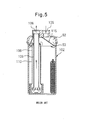
- FIG. 5 is a view which shows an accumulator of FIG. 9 of PLT 1.
- This accumulator is provided with an inlet 105 and outlet 106 of a fluid which are arranged in parallel at a top part of a pressure vessel 102, a double wall tube 108 which guides the gas refrigerant to the outlet, and a gas/liquid separating plate (umbrella-shaped member) 115 which spreads out in a substantially conical shape or umbrella shape so as to cover a gas refrigerant inflow port of the double wall tube 108.
- the gas/liquid dual phase state refrigerant which flows in from the inlet 105 is separated into a gas and liquid by striking the umbrella shaped member 115 whereby the gaseous refrigerant flows through a circumferential gap S3 between the umbrella shaped member 115 and the inside surface of the pressure vessel 102, flows from the top end of the outside tube 110 of the double wall tube to the inside of the double wall tube, descends, then rises inside the inside tube 109 and is sent from the outlet 106 to a compressor (not shown).
- the separated liquid refrigerant and oil which had been contained in the refrigerant flow down through the circumferential gap S3 between the umbrella shaped member and the inside wall of the vessel to be stored at the bottom part of the vessel.
- the flow cross-sectional area changes so as to expand while transitioning from the inflow port 105 to the space S2 above the umbrella shaped member 115, then being reduced at the circumferential gap S3 between the umbrella shaped member 115 and the vessel inside surface, but a relatively large pressure loss of the refrigerant occurred due to this change of the flow cross-sectional area.
- the accumulator according to the prior art which is shown in FIG. 5 sufficiently performs the function demanded and as a result the operation of the compressor can be suitably maintained, but there is the problem that the pressure loss which arises there is relatively large and as a result the refrigeration cycle system falls in efficiency.
- the present invention is made in consideration of the above problem and has as its object the provision of an accumulator for refrigerant use with a small pressure loss.
- the present invention provides an accumulator (1) arranged at a suction side of a compressor in a refrigerant circuit, and adapted to separate a refrigerant into a gas and liquid and store the liquid refrigerant, the accumulator (1) comprising a pressure vessel (2) which forms an inside space (S), an inflow port (5) of the refrigerant and an outflow port (6) of the refrigerant which are provided at the pressure vessel (2), a conduit (8) which guides the refrigerant in the pressure vessel (2) to the outflow port (6), and a gas-liquid separating means (15) comprising a separating plate (16) which is arranged in the pressure vessel (2) facing the inflow port (5) and spreads out substantially perpendicular to a flow line at the inflow port (5), wherein the gas-liquid separating means (15) has a peak shaped protrusion (18) which has a single crest (18a) projecting out in the direction of the inflow port (5) and a slanted surface (18b)
- the inflow of the refrigerant from the inflow port (5) can be smoothly converted to the substantially vertical direction and the separating plate (16) can be arranged in relative proximity to the inflow port (5) and the change of the flow cross-sectional area becomes smaller, so that the pressure loss of the refrigerant which occurs inside of the accumulator (1) can be kept small.
- the gas-liquid separating means (15) has a circumferential wall part (17) which runs around the separating plate (16) so as to define a space (S1) which opens at the opposite side to the inflow port (5) and wherein an inlet (11) of the conduit (8) is arranged preferably in the space (S1) defined by the gas-liquid separating means (15).
- the peak shaped protrusion (18) may have the shape of a cone.
- a slanted surface (18b) of the peak shaped protrusion (18) is preferably curved in a recessed shape.
- the crest (18a) of the peak shaped protrusion (18) may be positioned on the center axis (5x) of the inflow port (5).
- the outflow port (6) may be arranged substantially parallel to the inflow port (5) and the crest (18a) of the peak shaped protrusion (18) may be offset from the center axis (5x) of the inflow port (5) in a direction away from the outflow port (6).
- the conduit (8) which is connected to the inside of the outflow port (6) or the ring-shaped protrusion which is formed in the pressure vessel (2) for connecting the conduit (8) eases the extent of obstruction to the fluid which enters from the inflow port (5) and flows along the separating plate (16).
- an inside surface of the pressure vessel (2) which faces the separating plate (16) may extend in parallel to the separating plate (16) and the gap (g) between the separating plate (16) and the inside surface of the pressure vessel (2) may be 1/4 times or more of the inside diameter (D) of the inflow port (5).
- the crest (18a) of the peak shaped protrusion (18) may be of a height not more than the boundary surface of the inside space (S) of the pressure vessel (2) and the inflow port (5).
- the conduit (8) is preferably configured as a double wall tube which is comprised of an inside tube (9) and an outside tube (10) which surrounds the inside tube (9), where one end of the inside tube (9) is connected to the outflow port (6) and the other end is opened at the inside of the outside tube (10), and the end of the outside tube (10) which has an inlet (11) for introducing a gaseous refrigerant flares out in a trumpet shape.
- FIG. 1 An accumulator 1 according to an embodiment of the present invention will be explained while referring to the longitudinal cross-sectional view of FIG. 1 and FIG. 2 , which is an enlarged view of principal parts of FIG. 1 .
- the accumulator 1 which is shown in FIG. 1 is arranged at the suction side of a not shown compressor of an automobile-use refrigeration cycle system.
- the accumulator 1 comprises a cylindrically shaped pressure vessel 2 which forms an inside space S.
- the pressure vessel 2 has a deep, closed bottom tube-shaped vessel body 3 with an open top part and an overall substantially disk shaped lid member 4 which closes the open top part of the vessel body 3.
- the lid member 4 is joined with the vessel body 3 by welding, whereby the pressure vessel 2 is formed..
- the lid member 4 is provided with an inflow port 5 and outflow port 6 of a fluid which flows in the up-down direction of FIG. 1 .
- a feed pipe (not shown) which guides refrigerant from an evaporator is connected.
- the lid member 4 has a ring-shaped projecting part 7 around the outflow port 6 at the inner side.
- the projecting part 7 is connected to an inside tube 9 of a conduit 8, which is explained later.
- the accumulator 1 of FIG. 1 further comprises inside it the conduit 8 which guides refrigerant inside the pressure vessel 2 to the outflow port 6 and a gas-liquid separating means 15 which is provided facing the inflow port 5.
- the conduit 8 of the present embodiment is formed as a double wall tube 8 which is comprised of an inside tube 9 and an outside tube 10 which surrounds it.
- the double wall tube 8 extends vertically downward right under the outflow port 6.
- the top end of the inside tube 9 is joined to the outflow port 6 of the lid member 4 of the pressure vessel 2, while the bottom end opens inside of the outside tube 10.
- the outside tube 10 has an inlet 11 at the top end part which flares out in a trumpet shape.
- the inlet 11 is positioned at a height whereby it is included in the space S1 which the gas-liquid separating means 15 defines.
- the bottom end part of the outside tube extends up to close to the bottom of the pressure vessel 2.
- the bottom end part of the outside tube 10 is provided with a small oil return hole 12, but is closed, except for the hole 12.
- four fins 13 are provided extending from the inner circumferential surface of the substantially bottom half of the outside tube 10 toward the center until contiguous with the outer circumferential surface of the inside tube 9. Through these fins 13, the outside tube 10 is joined with the inside tube 9.
- the top end of the inside tube 9 is connected to the outflow port 6 by inserting the top end of the inside tube 9 into the ring-shaped projecting part 7 of the lid member 4, then enlarging it in diameter.
- a recessed part 16a which is formed at a later explained separating plate 16 of the gas-liquid separating means 15 is fastened by sandwiching it between the end face of the ring-shaped projecting part 7 of the lid member 4 and the inside tube 9, so a ring-shaped bead 14 is formed at the inside tube 9 by, for example, beading.
- the gas-liquid separating means 15 of the present embodiment has a separating plate 16 which spreads out substantially horizontally, as shown in FIG. 1 , in other words, substantially perpendicular to the direction of the flow lines at the inflow port 5, and a circumferential wall part 17 which extends downward from the outer circumferential part of the separating plate 16.
- the gas-liquid separating means 15 is formed with a space S1 which opens at the opposite side to the inflow port 5 by the separating plate 16 and the circumferential wall part 17. Inside of this space S1, as explained above, an inlet 11 of an outside tube 10 of the conduit 8 is opened.
- the gas-liquid separating means 15 has an integrally formed peak shaped protrusion 18 which has one crest 18a which protrudes the direction of the inflow port 5 and slanted surfaces 18b at the region of the separating plate 16 which faces the inflow port 5.
- the crest 18a of the protrusion 18 is arranged on the center axis 5x of the inflow port 5 in the present embodiment. The tip of the crest reaches exactly the inside open surface of the inflow port 5, i.e. the boundary surface between the inside space S of the pressure vessel 2, and more particularly, the later explained upper separating plate space S2, and the inflow port 5.
- the inside surface of the lid member 4 of the pressure vessel 2 extends flat and horizontally, except at the ring-shaped projecting part 7 at the inside of the outflow port 6.
- a space S2 which has a substantially uniform height "g", except at the region of the peak shaped protrusion 18 is formed.
- the space S2 will hereinafter be referred to as an "upper separating plate space S2".
- the gas-liquid separating means 15 is arranged so that the height "g" of the upper separating plate space S2 becomes 1/4 of the inside diameter D of the inflow port 5.
- the height "g" of the upper separating plate space S2, i.e. the gap “g” between the separating plate 16 and the inside surface of the lid member 4 differs in optimal value, depending on the conditions of the flow rate of the inflowing refrigerant and the size of a gap S3 between the circumferential wall part 17 of the gas-liquid separating means 15 and the inner circumferential surface of the pressure vessel (referred to below as a “circumferential wall gap S3") etc., but in general 1/4 to 1 time the inside diameter D of the inflow port 5 is preferable.
- the “inside diameter D of the inflow port” in the terms in this Description means the inside diameter D of the flow channel at the inflow side contiguous with the inside space S of the pressure vessel 2.
- the inside diameter D of the inflow port matches the inside diameter D of the inside open surface of the inflow port 5 which is formed in the lid member 4.
- the tip of the feed pipe from the evaporator is inserted up to the inside end face of the lid member 4, the inside diameter of the tip part of the feed pipe becomes the "inside diameter of the inflow port".
- the gas/liquid dual phase refrigerant which is discharged from the evaporator (not shown) is introduced from the inflow port 5 of the accumulator 1 substantially vertically downward such as shown by the arrow in FIG. 2 , and strikes the separating plate 16 of the substantially horizontally arranged gas-liquid separating means 15.
- the large mass liquid phase refrigerant and the oil which is contained in the refrigerant deposit on the front surface of the gas-liquid separating means 15 and the inside surface of the pressure vessel 2, drip downward from there, and are stored in the vessel 2.
- the gaseous refrigerant passes through the circumferential wall part gap S3, flows from the inlet 11 at the top end part of the outside tube 10 to the inside of the double wall tube 8, rises from the opening at the bottom end of the inside tube 9 through the inside of the inside tube 9 to reach the outflow port 6, and is discharged to the compressor (not shown).
- the liquid refrigerant which is stored close to the bottom part of the pressure vessel 2 and contains a large amount of oil is also sucked into the double wall tube 8 through the small oil return hole 12 which is provided at the bottom part of the outside tube 10 and returned to the compressor together with the gaseous refrigerant.
- the refrigerant which flows in from the inflow port 5 is smoothly converted in flow from a vertical to a horizontal direction by the action of the peak shaped protrusion 18 which is provided on that separating plate 16 facing the inflow port 5, so that pressure loss is reduced compared with when there is no peak shaped protrusion 18. Furthermore, since the height "g" of the upper separating plate space S2 is set to relatively less in the present embodiment, i.e. to 1/4 of the inside diameter D of the inflow port 5, the change in cross-sectional area of the flow is smaller.
- the rate of increase of the flow cross-sectional area of the upper separating plate space S2 to the flow cross-sectional area of the inflow port 5 and the rate of decrease of the flow cross-sectional area of the circumferential wall part gap S3 to the flow cross-sectional area of the upper separating plate space S2 is relatively smaller, and thus pressure loss of the refrigerant gas is kept small.
- the inlet 11 of the double wall tube 8 into which the separated gas refrigerant flows flares out in a trumpet shape, whereby pressure loss at this part is also kept small.
- the peak shaped protrusion 18 is shaped similar to a conical shape having a circular bottom in the above embodiment, and thus the slanted surface 18b is shaped curved in a recessed shape, an embodiment wherein the peak shaped protrusion 18 is a conical shape or a prismatic shape which has a straight slanted surface or surfaces 18b (not shown) is also possible.
- the tip of the crest 18a reaches exactly the inside open surface of the inflow port 5.
- the optimal value of the height of the peak shaped protrusion 18 differs, for example, depending on the height "g" of the upper separating plate space S2 as well.. Therefore, the pressure loss sometimes falls more in an embodiment wherein the height is lower than that of the embodiment of FIG. 3 and the tip does not reach the open surface (not shown).
- the ring-shaped projecting part 7 Since the outflow port 6 must be joined with the inside tube 9, the ring-shaped projecting part 7 is formed at the inside of the lid member 4. However, the ring-shaped projecting part 7 becomes an obstruction to the fluid which flows in from the inflow port 5 and flows toward the circumferential wall part 17. For this reason, to ease the effects of this obstacle and therefore the pressure loss, an embodiment is also possible wherein the horizontal direction position of the crest 18a of the peak shaped protrusion 18, as shown in FIG. 5 , is offset by a distance "e" from the center axis 5x of the inflow port 5 in a direction away from the outflow port 6.
- the peak shaped protrusion 18 is formed integrally with the separating plate 16.
- the peak shaped protrusion is a member separate from the separating plate and is comprised of a member which is attached to the separating plate by, for example, screws or other fastening means (not shown) is also possible.
- the gas-liquid separating means 15 of the above embodiment has a circumferential wall part 17.
- an embodiment wherein the gas-liquid separating means 15 does not have a circumferential wall part 17 (not shown) is also possible.
- the conduit 8 in the above embodiment is comprised of a double wall tube.
- the conduit 8 is a tubular structure other than a double wall tube, for example, wherein it is comprised of a single U-shaped tube which is bent in a U-shape, has one end connected to the outflow port 6, and has the other end opened inside of the inside space S of the pressure vessel 2 (not shown) is also possible.
Landscapes
- Engineering & Computer Science (AREA)
- Chemical & Material Sciences (AREA)
- Analytical Chemistry (AREA)
- Power Engineering (AREA)
- Physics & Mathematics (AREA)
- Mechanical Engineering (AREA)
- Thermal Sciences (AREA)
- General Engineering & Computer Science (AREA)
- Compressor (AREA)
- Applications Or Details Of Rotary Compressors (AREA)
- Air-Conditioning For Vehicles (AREA)
Abstract
Description
- The present invention relates to an accumulator which is arranged at a suction side of a compressor in a refrigerant circuit, separates the gas and liquid of the refrigerant, and stores the liquid refrigerant.,
- As the above-mentioned accumulator, there is known one of a type which arranges a gas-liquid separating plate at the inside and makes the gas/liquid dual phase refrigerant strike it, as shown in for example FIG. 9 of
PLT 1.FIG. 5 is a view which shows an accumulator of FIG. 9 ofPLT 1. This accumulator is provided with aninlet 105 andoutlet 106 of a fluid which are arranged in parallel at a top part of apressure vessel 102, adouble wall tube 108 which guides the gas refrigerant to the outlet, and a gas/liquid separating plate (umbrella-shaped member) 115 which spreads out in a substantially conical shape or umbrella shape so as to cover a gas refrigerant inflow port of thedouble wall tube 108. The gas/liquid dual phase state refrigerant which flows in from theinlet 105 is separated into a gas and liquid by striking the umbrellashaped member 115 whereby the gaseous refrigerant flows through a circumferential gap S3 between the umbrella shapedmember 115 and the inside surface of thepressure vessel 102, flows from the top end of theoutside tube 110 of the double wall tube to the inside of the double wall tube, descends, then rises inside theinside tube 109 and is sent from theoutlet 106 to a compressor (not shown). The separated liquid refrigerant and oil which had been contained in the refrigerant flow down through the circumferential gap S3 between the umbrella shaped member and the inside wall of the vessel to be stored at the bottom part of the vessel. - In this regard, in the accumulator of FIG. 9, the flow cross-sectional area changes so as to expand while transitioning from the
inflow port 105 to the space S2 above the umbrella shapedmember 115, then being reduced at the circumferential gap S3 between the umbrella shapedmember 115 and the vessel inside surface, but a relatively large pressure loss of the refrigerant occurred due to this change of the flow cross-sectional area. - PLT 1.
JP 2000-356439 A - The accumulator according to the prior art which is shown in
FIG. 5 sufficiently performs the function demanded and as a result the operation of the compressor can be suitably maintained, but there is the problem that the pressure loss which arises there is relatively large and as a result the refrigeration cycle system falls in efficiency. - The present invention is made in consideration of the above problem and has as its object the provision of an accumulator for refrigerant use with a small pressure loss.
- To solve the above problem, the present invention provides an accumulator (1) arranged at a suction side of a compressor in a refrigerant circuit, and adapted to separate a refrigerant into a gas and liquid and store the liquid refrigerant, the accumulator (1) comprising a pressure vessel (2) which forms an inside space (S), an inflow port (5) of the refrigerant and an outflow port (6) of the refrigerant which are provided at the pressure vessel (2), a conduit (8) which guides the refrigerant in the pressure vessel (2) to the outflow port (6), and a gas-liquid separating means (15) comprising a separating plate (16) which is arranged in the pressure vessel (2) facing the inflow port (5) and spreads out substantially perpendicular to a flow line at the inflow port (5), wherein the gas-liquid separating means (15) has a peak shaped protrusion (18) which has a single crest (18a) projecting out in the direction of the inflow port (5) and a slanted surface (18b) on the separating plate (16) at a region facing the inflow port (5).
- Accordingly, due to the effect of the peak shaped protrusion (18), the inflow of the refrigerant from the inflow port (5) can be smoothly converted to the substantially vertical direction and the separating plate (16) can be arranged in relative proximity to the inflow port (5) and the change of the flow cross-sectional area becomes smaller, so that the pressure loss of the refrigerant which occurs inside of the accumulator (1) can be kept small.
- In the present invention, the gas-liquid separating means (15) has a circumferential wall part (17) which runs around the separating plate (16) so as to define a space (S1) which opens at the opposite side to the inflow port (5) and wherein an inlet (11) of the conduit (8) is arranged preferably in the space (S1) defined by the gas-liquid separating means (15). By virtue of this arrangement, the liquid refrigerant is prevented from entering inside the conduit (8) from the inlet (11) of the conduit (8).
- In the present invention, the peak shaped protrusion (18) may have the shape of a cone.
- In the present invention, a slanted surface (18b) of the peak shaped protrusion (18) is preferably curved in a recessed shape.
- In the present invention, the crest (18a) of the peak shaped protrusion (18) may be positioned on the center axis (5x) of the inflow port (5).
- In the present invention, the outflow port (6) may be arranged substantially parallel to the inflow port (5) and the crest (18a) of the peak shaped protrusion (18) may be offset from the center axis (5x) of the inflow port (5) in a direction away from the outflow port (6). By virtue of this arrangement, the conduit (8) which is connected to the inside of the outflow port (6) or the ring-shaped protrusion which is formed in the pressure vessel (2) for connecting the conduit (8) eases the extent of obstruction to the fluid which enters from the inflow port (5) and flows along the separating plate (16).
- In the present invention, an inside surface of the pressure vessel (2) which faces the separating plate (16) may extend in parallel to the separating plate (16) and the gap (g) between the separating plate (16) and the inside surface of the pressure vessel (2) may be 1/4 times or more of the inside diameter (D) of the inflow port (5).
- In the present invention, the crest (18a) of the peak shaped protrusion (18) may be of a height not more than the boundary surface of the inside space (S) of the pressure vessel (2) and the inflow port (5).
- In the present invention, the conduit (8) is preferably configured as a double wall tube which is comprised of an inside tube (9) and an outside tube (10) which surrounds the inside tube (9), where one end of the inside tube (9) is connected to the outflow port (6) and the other end is opened at the inside of the outside tube (10), and the end of the outside tube (10) which has an inlet (11) for introducing a gaseous refrigerant flares out in a trumpet shape. By virtue of this arrangement, it is possible to suppress pressure loss of the gaseous refrigerant at the inlet (11) of the conduit (8).
-
-
FIG. 1 is a longitudinal cross-sectional view of an accumulator according to an embodiment of the present invention. -
FIG. 2 is a partial enlarged longitudinal cross-sectional view of a top part of an accumulator ofFIG. 1 . -
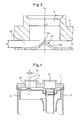
FIG. 3 is a further partial enlarged longitudinal cross-sectional view of principal parts ofFIG. 2 . -
FIG. 4 is a partial enlarged longitudinal cross-sectional view of a top part of a modification of an accumulator according to an embodiment of the present invention. -
FIG. 5 is a longitudinal cross-sectional view according to the prior art. - An
accumulator 1 according to an embodiment of the present invention will be explained while referring to the longitudinal cross-sectional view ofFIG. 1 and FIG. 2 , which is an enlarged view of principal parts ofFIG. 1 . - The
accumulator 1 which is shown inFIG. 1 is arranged at the suction side of a not shown compressor of an automobile-use refrigeration cycle system. Theaccumulator 1 comprises a cylindricallyshaped pressure vessel 2 which forms an inside space S. Thepressure vessel 2 has a deep, closed bottom tube-shaped vessel body 3 with an open top part and an overall substantially disk shapedlid member 4 which closes the open top part of thevessel body 3. Thelid member 4 is joined with thevessel body 3 by welding, whereby thepressure vessel 2 is formed.. Thelid member 4 is provided with aninflow port 5 andoutflow port 6 of a fluid which flows in the up-down direction ofFIG. 1 . At the outside of theinflow port 5, a feed pipe (not shown) which guides refrigerant from an evaporator is connected. At the outside of theoutflow port 6, a discharge pipe (not shown) which discharges refrigerant to the compressor is connected. Thelid member 4 has a ring-shaped projecting part 7 around theoutflow port 6 at the inner side. The projecting part 7 is connected to an inside tube 9 of a conduit 8, which is explained later. - The
accumulator 1 ofFIG. 1 further comprises inside it the conduit 8 which guides refrigerant inside thepressure vessel 2 to theoutflow port 6 and a gas-liquid separating means 15 which is provided facing theinflow port 5. The conduit 8 of the present embodiment is formed as a double wall tube 8 which is comprised of an inside tube 9 and anoutside tube 10 which surrounds it. The double wall tube 8 extends vertically downward right under theoutflow port 6. The top end of the inside tube 9 is joined to theoutflow port 6 of thelid member 4 of thepressure vessel 2, while the bottom end opens inside of theoutside tube 10. Theoutside tube 10 has aninlet 11 at the top end part which flares out in a trumpet shape. Theinlet 11 is positioned at a height whereby it is included in the space S1 which the gas-liquid separating means 15 defines. The bottom end part of the outside tube extends up to close to the bottom of thepressure vessel 2. The bottom end part of theoutside tube 10 is provided with a smalloil return hole 12, but is closed, except for thehole 12. Furthermore, four fins 13 (inFIG. 1 , only two shown) are provided extending from the inner circumferential surface of the substantially bottom half of theoutside tube 10 toward the center until contiguous with the outer circumferential surface of the inside tube 9. Through thesefins 13, theoutside tube 10 is joined with the inside tube 9. - The top end of the inside tube 9 is connected to the
outflow port 6 by inserting the top end of the inside tube 9 into the ring-shaped projecting part 7 of thelid member 4, then enlarging it in diameter.. At this time, arecessed part 16a which is formed at a later explained separatingplate 16 of the gas-liquid separating means 15 is fastened by sandwiching it between the end face of the ring-shaped projecting part 7 of thelid member 4 and the inside tube 9, so a ring-shaped bead 14 is formed at the inside tube 9 by, for example, beading. - The gas-liquid separating means 15 of the present embodiment has a
separating plate 16 which spreads out substantially horizontally, as shown inFIG. 1 , in other words, substantially perpendicular to the direction of the flow lines at theinflow port 5, and acircumferential wall part 17 which extends downward from the outer circumferential part of theseparating plate 16. The gas-liquid separating means 15 is formed with a space S1 which opens at the opposite side to theinflow port 5 by theseparating plate 16 and thecircumferential wall part 17. Inside of this space S1, as explained above, aninlet 11 of anoutside tube 10 of the conduit 8 is opened. The gas-liquid separating means 15 has an integrally formed peak shapedprotrusion 18 which has onecrest 18a which protrudes the direction of theinflow port 5 andslanted surfaces 18b at the region of theseparating plate 16 which faces theinflow port 5. The peak shapedprotrusion 18, as shown by the further partial enlarged view ofFIG. 2 constituted byFIG. 3 , is shaped similar to a cone which has a round bottom surface in the present embodiment, but theslanted surface 18b is curved in a recessed shape and therefore the shape is different from a conical shape. Thecrest 18a of theprotrusion 18 is arranged on thecenter axis 5x of theinflow port 5 in the present embodiment. The tip of the crest reaches exactly the inside open surface of theinflow port 5, i.e. the boundary surface between the inside space S of thepressure vessel 2, and more particularly, the later explained upper separating plate space S2, and theinflow port 5. - The inside surface of the
lid member 4 of thepressure vessel 2 extends flat and horizontally, except at the ring-shaped projecting part 7 at the inside of theoutflow port 6. As a result, with the separatingplate 16 of the gas-liquid separating means 15, a space S2 which has a substantially uniform height "g", except at the region of the peak shapedprotrusion 18 is formed. It should be noted that the space S2 will hereinafter be referred to as an "upper separating plate space S2". In the accumulator shown inFIGS. 1 to 3 , the gas-liquid separating means 15 is arranged so that the height "g" of the upper separating plate space S2 becomes 1/4 of the inside diameter D of theinflow port 5. In the structure of this embodiment of the present invention, the height "g" of the upper separating plate space S2, i.e. the gap "g" between the separatingplate 16 and the inside surface of thelid member 4, differs in optimal value, depending on the conditions of the flow rate of the inflowing refrigerant and the size of a gap S3 between thecircumferential wall part 17 of the gas-liquid separating means 15 and the inner circumferential surface of the pressure vessel (referred to below as a "circumferential wall gap S3") etc., but in general 1/4 to 1 time the inside diameter D of theinflow port 5 is preferable. - The "inside diameter D of the inflow port" in the terms in this Description means the inside diameter D of the flow channel at the inflow side contiguous with the inside space S of the
pressure vessel 2. As a result, in the case of the embodiment which is shown inFIGS. 1 to 3 , "the inside diameter D of the inflow port" matches the inside diameter D of the inside open surface of theinflow port 5 which is formed in thelid member 4. However, in another not shown embodiment, when the tip of the feed pipe from the evaporator is inserted up to the inside end face of thelid member 4, the inside diameter of the tip part of the feed pipe becomes the "inside diameter of the inflow port". - Next, how an
accumulator 1 of the embodiment ofFIG. 1 operates will be explained. - The gas/liquid dual phase refrigerant which is discharged from the evaporator (not shown) is introduced from the
inflow port 5 of theaccumulator 1 substantially vertically downward such as shown by the arrow inFIG. 2 , and strikes the separatingplate 16 of the substantially horizontally arranged gas-liquid separating means 15. As a result, the large mass liquid phase refrigerant and the oil which is contained in the refrigerant deposit on the front surface of the gas-liquid separating means 15 and the inside surface of thepressure vessel 2, drip downward from there, and are stored in thevessel 2. On the other hand, the gaseous refrigerant passes through the circumferential wall part gap S3, flows from theinlet 11 at the top end part of theoutside tube 10 to the inside of the double wall tube 8, rises from the opening at the bottom end of the inside tube 9 through the inside of the inside tube 9 to reach theoutflow port 6, and is discharged to the compressor (not shown). - In the
accumulator 1 of the present embodiment, the liquid refrigerant which is stored close to the bottom part of thepressure vessel 2 and contains a large amount of oil is also sucked into the double wall tube 8 through the smalloil return hole 12 which is provided at the bottom part of theoutside tube 10 and returned to the compressor together with the gaseous refrigerant. - In the
accumulator 1 of the present embodiment, the refrigerant which flows in from theinflow port 5 is smoothly converted in flow from a vertical to a horizontal direction by the action of the peak shapedprotrusion 18 which is provided on that separatingplate 16 facing theinflow port 5, so that pressure loss is reduced compared with when there is no peak shapedprotrusion 18. Furthermore, since the height "g" of the upper separating plate space S2 is set to relatively less in the present embodiment, i.e. to 1/4 of the inside diameter D of theinflow port 5, the change in cross-sectional area of the flow is smaller. More specifically, the rate of increase of the flow cross-sectional area of the upper separating plate space S2 to the flow cross-sectional area of theinflow port 5 and the rate of decrease of the flow cross-sectional area of the circumferential wall part gap S3 to the flow cross-sectional area of the upper separating plate space S2 is relatively smaller, and thus pressure loss of the refrigerant gas is kept small. - Further, the
inlet 11 of the double wall tube 8 into which the separated gas refrigerant flows flares out in a trumpet shape, whereby pressure loss at this part is also kept small.. - While the peak shaped
protrusion 18 is shaped similar to a conical shape having a circular bottom in the above embodiment, and thus theslanted surface 18b is shaped curved in a recessed shape, an embodiment wherein the peak shapedprotrusion 18 is a conical shape or a prismatic shape which has a straight slanted surface or surfaces 18b (not shown) is also possible. - In the peak shaped
protrusion 18 of the above embodiment, the tip of thecrest 18a reaches exactly the inside open surface of theinflow port 5. However, the optimal value of the height of the peak shapedprotrusion 18 differs, for example, depending on the height "g" of the upper separating plate space S2 as well.. Therefore, the pressure loss sometimes falls more in an embodiment wherein the height is lower than that of the embodiment ofFIG. 3 and the tip does not reach the open surface (not shown). - Since the
outflow port 6 must be joined with the inside tube 9, the ring-shaped projecting part 7 is formed at the inside of thelid member 4. However, the ring-shaped projecting part 7 becomes an obstruction to the fluid which flows in from theinflow port 5 and flows toward thecircumferential wall part 17. For this reason, to ease the effects of this obstacle and therefore the pressure loss, an embodiment is also possible wherein the horizontal direction position of thecrest 18a of the peak shapedprotrusion 18, as shown inFIG. 5 , is offset by a distance "e" from thecenter axis 5x of theinflow port 5 in a direction away from theoutflow port 6. It should be noted that while not shown, a structure wherein the inside tube 9 is joined with theoutflow port 6 without forming the ring-shaped projecting part 7 at the inside of thelid member 4 is also easily possible, although in such a case, the inside tube 9 itself becomes an obstruction to the flow of the gaseous refrigerant. - In the embodiment of
FIG. 1 to 3 , the peak shapedprotrusion 18 is formed integrally with the separatingplate 16. However, an embodiment wherein the peak shaped protrusion is a member separate from the separating plate and is comprised of a member which is attached to the separating plate by, for example, screws or other fastening means (not shown) is also possible. - The gas-liquid separating means 15 of the above embodiment has a
circumferential wall part 17. However, an embodiment wherein the gas-liquid separating means 15 does not have a circumferential wall part 17 (not shown) is also possible. - The conduit 8 in the above embodiment is comprised of a double wall tube. However, an embodiment wherein the conduit 8 is a tubular structure other than a double wall tube, for example, wherein it is comprised of a single U-shaped tube which is bent in a U-shape, has one end connected to the
outflow port 6, and has the other end opened inside of the inside space S of the pressure vessel 2 (not shown) is also possible. - While the present invention is explained in detail based on specific embodiments, it should be apparent that a person skilled in the art could make various changes, corrections, etc. without departing from the scope of the claims and overall concept of the present invention..
-
- 1
- accumulator
- 2
- pressure vessel
- 3
- vessel body
- 4
- lid member
- 5
- inflow port
- 6
- outflow port
- 8
- conduit
- 9
- inside tube
- 10
- outside tube
- 11
- inlet
- 15
- gas-liquid separating means
- 16
- separating plate
- 17
- circumferential wall part
- 18
- peak shaped protrusion
Claims (9)
- An accumulator (1) arranged at a suction side of a compressor in a refrigerant circuit, and adapted to separate a refrigerant into a gas and liquid and store the liquid refrigerant, the accumulator (1) comprising:a pressure vessel (2) which forms an inside space (S);an inflow port (5) of the refrigerant and an outflow port (6) of the refrigerant which are provided at the pressure vessel (2);a conduit (8) which guides the refrigerant in the pressure vessel (2) to the outflow port (6), anda gas-liquid separating means (15) comprising a separating plate (16) which is arranged in the pressure vessel (2) facing the inflow port (5) and spreads out substantially perpendicular to a flow line at the inflow port (5);wherein the gas-liquid separating means (15) has a peak shaped protrusion (18) which has a single crest (18a) projecting out in the direction of the inflow port (5) and a slanted surface (18b) on the separating plate (16) at a region facing the inflow port (5).
- The accumulator (1) according to claim 1, wherein the gas-liquid separating means (15) has a circumferential wall part (17) which runs around the separating plate (16) so as to define a space (S1) which opens at the opposite side to the inflow port (5) and wherein an inlet (11) of the conduit (8) is arranged in the space (S1) defined by the gas-liquid separating means (15).
- The accumulator (1) according to claim 1 or 2, wherein the peak shaped protrusion (18) has the shape of a cone.
- The accumulator (1) according to claim 1 or 2, wherein the slanted surface (18b) of the peak shaped protrusion (18) is curved in a recessed shape.
- The accumulator (1) according to any one of claims 1 to 4, wherein the crest (18a) of the peak shaped protrusion (18) is positioned on a center axis (5x) of the inflow port (5).
- The accumulator (1) according to any one of claims 1 to 4, wherein
the outflow port (6) is arranged substantially in parallel to the inflow port (5), and
the crest (18a) of the peak shaped protrusion (18) is offset from the center axis (5x) of the inflow port (5) in a direction away from the outflow port (6). - The accumulator (1) according to any one of claims 1 to 6, wherein
an inside surface of the pressure vessel (2) which faces the separating plate (16) extends in parallel to the separating plate (16), and
a gap (g) between the separating plate (16) and the inside surface of the pressure vessel (2) is 1/4 times or more the inside diameter (D) of the inflow port (5). - The accumulator (1) according to any one of claims 1 to 7, wherein the crest (18a) of the peak shaped protrusion (18) is of a height not more than a boundary surface between the inside space (S) of the pressure vessel (2) and the inflow port (5).
- The accumulator (1) according to any one of claims 1 to 8, wherein
the conduit (8) is configured as a double wall tube which is comprised of an inside tube (9) and an outside tube (10) which surrounds the inside tube (9),
one end of the inside tube (9) is connected to the outflow port (6) and the other end is opened at the inside of the outside tube (10), and
the end of the outside tube (10) which has an inlet (11) for introducing of a gaseous refrigerant flares out in a trumpet shape.
Applications Claiming Priority (2)
| Application Number | Priority Date | Filing Date | Title |
|---|---|---|---|
| JP2011260889A JP5760993B2 (en) | 2011-11-29 | 2011-11-29 | accumulator |
| PCT/JP2012/072633 WO2013080620A1 (en) | 2011-11-29 | 2012-09-05 | Accumulator |
Publications (3)
| Publication Number | Publication Date |
|---|---|
| EP2787306A1 true EP2787306A1 (en) | 2014-10-08 |
| EP2787306A4 EP2787306A4 (en) | 2015-06-24 |
| EP2787306B1 EP2787306B1 (en) | 2019-05-08 |
Family
ID=48535097
Family Applications (1)
| Application Number | Title | Priority Date | Filing Date |
|---|---|---|---|
| EP12852573.0A Not-in-force EP2787306B1 (en) | 2011-11-29 | 2012-09-05 | Accumulator |
Country Status (5)
| Country | Link |
|---|---|
| US (1) | US9541316B2 (en) |
| EP (1) | EP2787306B1 (en) |
| JP (1) | JP5760993B2 (en) |
| CN (1) | CN103842748B (en) |
| WO (1) | WO2013080620A1 (en) |
Cited By (3)
| Publication number | Priority date | Publication date | Assignee | Title |
|---|---|---|---|---|
| US9636622B2 (en) | 2012-09-07 | 2017-05-02 | Denso Corporation | Accumulator |
| KR20190038909A (en) * | 2016-10-25 | 2019-04-09 | 가부시기가이샤 후지고오키 | Accumulator |
| CN114234497A (en) * | 2021-12-21 | 2022-03-25 | 珠海格力电器股份有限公司 | Liquid storage device and compressor assembly |
Families Citing this family (18)
| Publication number | Priority date | Publication date | Assignee | Title |
|---|---|---|---|---|
| FR3020417A1 (en) * | 2014-04-23 | 2015-10-30 | Inergy Automotive Systems Res | PRESSURE ACCUMULATOR |
| JP6767099B2 (en) * | 2015-07-07 | 2020-10-14 | 株式会社不二工機 | accumulator |
| JP6537911B2 (en) * | 2015-07-17 | 2019-07-03 | 株式会社不二工機 | accumulator |
| JP2019070450A (en) * | 2016-02-26 | 2019-05-09 | 株式会社デンソー | accumulator |
| JP6500839B2 (en) | 2016-05-19 | 2019-04-17 | 株式会社デンソー | Accumulator and refrigeration cycle |
| JP6341958B2 (en) * | 2016-08-17 | 2018-06-13 | 株式会社不二工機 | accumulator |
| EP3604977B1 (en) * | 2017-03-24 | 2023-10-11 | Mitsubishi Electric Corporation | Refrigeration cycle apparatus |
| US10845106B2 (en) * | 2017-12-12 | 2020-11-24 | Rheem Manufacturing Company | Accumulator and oil separator |
| KR102750535B1 (en) * | 2019-05-31 | 2025-01-06 | 현대자동차 주식회사 | Gas-liquid separation device for vehicle |
| CN110849048A (en) * | 2019-12-10 | 2020-02-28 | 上海交通大学 | Gas-liquid separator for automobile heat pump air conditioner |
| CN111486611A (en) * | 2020-04-24 | 2020-08-04 | 深圳麦克维尔空调有限公司 | Air conditioning system and control method thereof |
| JP2023544380A (en) * | 2020-10-06 | 2023-10-23 | カミンズ フィルトレーション インコーポレイテッド | Air purifier with water separation |
| DE102021125240A1 (en) * | 2020-11-20 | 2022-05-25 | Hanon Systems | Device for separating a gaseous and a liquid phase of a working substance and for storing the liquid phase |
| CN115106648B (en) * | 2021-03-17 | 2025-12-02 | 浙江三花汽车零部件有限公司 | A container and its manufacturing method |
| CN113280542B (en) * | 2021-05-08 | 2022-09-09 | 三花控股集团有限公司 | Gas-liquid separator |
| CN113266969B (en) * | 2021-05-08 | 2022-09-09 | 三花控股集团有限公司 | Gas-liquid separator |
| CN113266970A (en) * | 2021-05-25 | 2021-08-17 | 三花控股集团有限公司 | Gas-liquid separator |
| WO2023128458A1 (en) * | 2021-12-31 | 2023-07-06 | 한온시스템 주식회사 | Vehicle accumulator |
Family Cites Families (36)
| Publication number | Priority date | Publication date | Assignee | Title |
|---|---|---|---|---|
| US4111005A (en) * | 1977-04-07 | 1978-09-05 | General Motors Corporation | Press-on plastic baffle for accumulator-dehydrator |
| US4270934A (en) * | 1978-06-05 | 1981-06-02 | General Motors Corporation | Universal internal tube accumulator |
| JPS624848Y2 (en) | 1979-03-01 | 1987-02-04 | ||
| JPS6050767A (en) | 1983-08-31 | 1985-03-20 | Toshiba Corp | Reproducing device of disk record |
| JPS6050767U (en) * | 1983-09-13 | 1985-04-10 | ダイキン工業株式会社 | Accumulator |
| JPS60188971A (en) | 1984-03-07 | 1985-09-26 | Fujitsu Ltd | Conductive path forming method |
| JPS60188971U (en) * | 1984-05-25 | 1985-12-14 | 株式会社東芝 | Accumulator |
| JPS61172975U (en) * | 1985-04-17 | 1986-10-27 | ||
| US4651540A (en) * | 1986-03-21 | 1987-03-24 | Tecumseh Products Company | Suction accumulator including an entrance baffle |
| US4768355A (en) * | 1987-01-27 | 1988-09-06 | Ford Motor Company | Accumulator with refrigerant processing cartridge for automotive air conditioning system |
| JPH0540308Y2 (en) * | 1987-02-06 | 1993-10-13 | ||
| US4827725A (en) * | 1988-07-05 | 1989-05-09 | Tecumseh Products Company | Suction accumulator with dirt trap |
| US5052193A (en) * | 1990-05-07 | 1991-10-01 | General Motors Corporation | Air conditioning system accumulator |
| US5076071A (en) * | 1990-05-08 | 1991-12-31 | Tecumseh Products Company | Suction accumulator with dirt trap and filter |
| US5179844A (en) * | 1991-07-16 | 1993-01-19 | General Motors Corporation | Liquid accumulator |
| JPH0744237U (en) * | 1992-07-22 | 1995-11-07 | 三星電子株式会社 | Accumulator structure of air conditioner for both air conditioning and heating |
| JPH0635601U (en) | 1992-10-14 | 1994-05-13 | サンデン株式会社 | accumulator |
| JP2724275B2 (en) * | 1993-01-25 | 1998-03-09 | 株式会社東芝 | Gas-liquid two-phase fluid distributor |
| JPH09133437A (en) | 1995-11-06 | 1997-05-20 | Showa Alum Corp | Accumulator |
| JPH1062037A (en) | 1996-08-21 | 1998-03-06 | Mitsubishi Electric Corp | accumulator |
| US5787729A (en) * | 1997-06-04 | 1998-08-04 | Automotive Fluid Systems, Inc. | Accumulator deflector |
| US5868001A (en) * | 1997-12-05 | 1999-02-09 | Carrier Corporation | Suction accumulator with oil reservoir |
| US6178771B1 (en) * | 1999-03-29 | 2001-01-30 | Carrier Corporation | Suction accumulator |
| JP2000320930A (en) * | 1999-05-11 | 2000-11-24 | Matsushita Refrig Co Ltd | Refrigerator |
| JP2000329430A (en) * | 1999-05-20 | 2000-11-30 | Fujitsu General Ltd | Oil separator |
| JP2000356439A (en) | 1999-06-16 | 2000-12-26 | Denso Corp | accumulator |
| JP2002130871A (en) * | 2000-10-30 | 2002-05-09 | Denso Corp | accumulator |
| JP2005164109A (en) * | 2003-12-02 | 2005-06-23 | Matsushita Electric Ind Co Ltd | accumulator |
| JP2005163744A (en) * | 2003-12-05 | 2005-06-23 | Matsushita Electric Ind Co Ltd | accumulator |
| US7461519B2 (en) * | 2005-02-03 | 2008-12-09 | Halla Climate Control Canada, Inc. | Accumulator with deflector |
| JP4682745B2 (en) * | 2005-08-16 | 2011-05-11 | パナソニック株式会社 | Hermetic compressor |
| DE102005059482A1 (en) * | 2005-12-07 | 2007-06-14 | Visteon Global Technologies, Inc., Van Buren | Refrigerant accumulator with liquid separator |
| JP2009047393A (en) * | 2007-08-22 | 2009-03-05 | Denso Corp | Refrigeration cycle apparatus and accumulator |
| JP2010096483A (en) | 2008-10-17 | 2010-04-30 | Nichirei Kogyo Kk | Gas-liquid separating device and refrigerating device including the same |
| CN201724482U (en) * | 2010-05-12 | 2011-01-26 | 珠海格力电器股份有限公司 | Refrigerant vapor-liquid separation and liquid storage integrated device and air conditioning system using same |
| WO2012026004A1 (en) * | 2010-08-25 | 2012-03-01 | 三菱電機株式会社 | Accumulator, vapor compression refrigeration cycle device, and gas-liquid separation method |
-
2011
- 2011-11-29 JP JP2011260889A patent/JP5760993B2/en not_active Expired - Fee Related
-
2012
- 2012-09-05 EP EP12852573.0A patent/EP2787306B1/en not_active Not-in-force
- 2012-09-05 CN CN201280048573.0A patent/CN103842748B/en active Active
- 2012-09-05 US US14/360,827 patent/US9541316B2/en active Active
- 2012-09-05 WO PCT/JP2012/072633 patent/WO2013080620A1/en not_active Ceased
Cited By (6)
| Publication number | Priority date | Publication date | Assignee | Title |
|---|---|---|---|---|
| US9636622B2 (en) | 2012-09-07 | 2017-05-02 | Denso Corporation | Accumulator |
| KR20190038909A (en) * | 2016-10-25 | 2019-04-09 | 가부시기가이샤 후지고오키 | Accumulator |
| EP3534092A4 (en) * | 2016-10-25 | 2020-06-24 | Fujikoki Corporation | Accumulator |
| US10989457B2 (en) | 2016-10-25 | 2021-04-27 | Fujikoki Corporation | Accumulator |
| CN114234497A (en) * | 2021-12-21 | 2022-03-25 | 珠海格力电器股份有限公司 | Liquid storage device and compressor assembly |
| CN114234497B (en) * | 2021-12-21 | 2022-11-18 | 珠海格力电器股份有限公司 | Liquid storage device and compressor assembly |
Also Published As
| Publication number | Publication date |
|---|---|
| CN103842748B (en) | 2016-01-13 |
| US20140331713A1 (en) | 2014-11-13 |
| EP2787306B1 (en) | 2019-05-08 |
| US9541316B2 (en) | 2017-01-10 |
| JP2013113508A (en) | 2013-06-10 |
| WO2013080620A1 (en) | 2013-06-06 |
| EP2787306A4 (en) | 2015-06-24 |
| CN103842748A (en) | 2014-06-04 |
| JP5760993B2 (en) | 2015-08-12 |
Similar Documents
| Publication | Publication Date | Title |
|---|---|---|
| EP2787306B1 (en) | Accumulator | |
| US4182136A (en) | Suction accumulator | |
| EP3479888A1 (en) | Gas-liquid separator | |
| JP2012139681A (en) | Arrangement for separating liquid from gas | |
| JP5439026B2 (en) | Gas-liquid separator | |
| EP3502589B1 (en) | Horizontal gas-liquid separator for air conditioner, and air conditioner | |
| JP6621132B2 (en) | Centrifugal oil separator and refrigeration cycle apparatus using the same | |
| CN104949406A (en) | Gas-liquid separator | |
| JP6175228B2 (en) | accumulator | |
| JP2013148308A (en) | Oil separator | |
| CN102230704B (en) | Centrifugal oil-gas separator | |
| CN108619795B (en) | Gas-liquid separator, refrigeration device provided with gas-liquid separator, and fluid machinery device provided with gas-liquid separator | |
| CN103657313A (en) | Gas-liquid separator | |
| JP5620736B2 (en) | Refrigerant tank and its header | |
| JP5803263B2 (en) | Gas-liquid separator | |
| EP3006864B1 (en) | Oil separator and method for manufacturing oil separator | |
| JP2014105907A (en) | Accumulator | |
| JP5887157B2 (en) | Gas-liquid separator | |
| WO2016023318A1 (en) | Screw compressor and oil-separating barrel component thereof | |
| JP5804911B2 (en) | Gas-liquid separator | |
| CN105091429B (en) | Liquid reservoir and its fixing device | |
| CN202204221U (en) | Centrifugal oil and gas separator | |
| JP5982114B2 (en) | Gas-liquid separator | |
| JP2014159919A (en) | Oil separator | |
| CN208365882U (en) | Liquid separator and compressor |
Legal Events
| Date | Code | Title | Description |
|---|---|---|---|
| PUAI | Public reference made under article 153(3) epc to a published international application that has entered the european phase |
Free format text: ORIGINAL CODE: 0009012 |
|
| 17P | Request for examination filed |
Effective date: 20140520 |
|
| AK | Designated contracting states |
Kind code of ref document: A1 Designated state(s): AL AT BE BG CH CY CZ DE DK EE ES FI FR GB GR HR HU IE IS IT LI LT LU LV MC MK MT NL NO PL PT RO RS SE SI SK SM TR |
|
| DAX | Request for extension of the european patent (deleted) | ||
| RA4 | Supplementary search report drawn up and despatched (corrected) |
Effective date: 20150521 |
|
| RIC1 | Information provided on ipc code assigned before grant |
Ipc: F25B 43/00 20060101AFI20150515BHEP |
|
| GRAP | Despatch of communication of intention to grant a patent |
Free format text: ORIGINAL CODE: EPIDOSNIGR1 |
|
| STAA | Information on the status of an ep patent application or granted ep patent |
Free format text: STATUS: GRANT OF PATENT IS INTENDED |
|
| INTG | Intention to grant announced |
Effective date: 20181127 |
|
| GRAS | Grant fee paid |
Free format text: ORIGINAL CODE: EPIDOSNIGR3 |
|
| GRAA | (expected) grant |
Free format text: ORIGINAL CODE: 0009210 |
|
| STAA | Information on the status of an ep patent application or granted ep patent |
Free format text: STATUS: THE PATENT HAS BEEN GRANTED |
|
| AK | Designated contracting states |
Kind code of ref document: B1 Designated state(s): AL AT BE BG CH CY CZ DE DK EE ES FI FR GB GR HR HU IE IS IT LI LT LU LV MC MK MT NL NO PL PT RO RS SE SI SK SM TR |
|
| REG | Reference to a national code |
Ref country code: GB Ref legal event code: FG4D |
|
| REG | Reference to a national code |
Ref country code: CH Ref legal event code: EP Ref country code: AT Ref legal event code: REF Ref document number: 1130785 Country of ref document: AT Kind code of ref document: T Effective date: 20190515 |
|
| REG | Reference to a national code |
Ref country code: DE Ref legal event code: R096 Ref document number: 602012060015 Country of ref document: DE |
|
| REG | Reference to a national code |
Ref country code: IE Ref legal event code: FG4D |
|
| REG | Reference to a national code |
Ref country code: NL Ref legal event code: MP Effective date: 20190508 |
|
| REG | Reference to a national code |
Ref country code: LT Ref legal event code: MG4D |
|
| PG25 | Lapsed in a contracting state [announced via postgrant information from national office to epo] |
Ref country code: NO Free format text: LAPSE BECAUSE OF FAILURE TO SUBMIT A TRANSLATION OF THE DESCRIPTION OR TO PAY THE FEE WITHIN THE PRESCRIBED TIME-LIMIT Effective date: 20190808 Ref country code: AL Free format text: LAPSE BECAUSE OF FAILURE TO SUBMIT A TRANSLATION OF THE DESCRIPTION OR TO PAY THE FEE WITHIN THE PRESCRIBED TIME-LIMIT Effective date: 20190508 Ref country code: FI Free format text: LAPSE BECAUSE OF FAILURE TO SUBMIT A TRANSLATION OF THE DESCRIPTION OR TO PAY THE FEE WITHIN THE PRESCRIBED TIME-LIMIT Effective date: 20190508 Ref country code: PT Free format text: LAPSE BECAUSE OF FAILURE TO SUBMIT A TRANSLATION OF THE DESCRIPTION OR TO PAY THE FEE WITHIN THE PRESCRIBED TIME-LIMIT Effective date: 20190908 Ref country code: SE Free format text: LAPSE BECAUSE OF FAILURE TO SUBMIT A TRANSLATION OF THE DESCRIPTION OR TO PAY THE FEE WITHIN THE PRESCRIBED TIME-LIMIT Effective date: 20190508 Ref country code: HR Free format text: LAPSE BECAUSE OF FAILURE TO SUBMIT A TRANSLATION OF THE DESCRIPTION OR TO PAY THE FEE WITHIN THE PRESCRIBED TIME-LIMIT Effective date: 20190508 Ref country code: LT Free format text: LAPSE BECAUSE OF FAILURE TO SUBMIT A TRANSLATION OF THE DESCRIPTION OR TO PAY THE FEE WITHIN THE PRESCRIBED TIME-LIMIT Effective date: 20190508 Ref country code: NL Free format text: LAPSE BECAUSE OF FAILURE TO SUBMIT A TRANSLATION OF THE DESCRIPTION OR TO PAY THE FEE WITHIN THE PRESCRIBED TIME-LIMIT Effective date: 20190508 Ref country code: ES Free format text: LAPSE BECAUSE OF FAILURE TO SUBMIT A TRANSLATION OF THE DESCRIPTION OR TO PAY THE FEE WITHIN THE PRESCRIBED TIME-LIMIT Effective date: 20190508 |
|
| PG25 | Lapsed in a contracting state [announced via postgrant information from national office to epo] |
Ref country code: BG Free format text: LAPSE BECAUSE OF FAILURE TO SUBMIT A TRANSLATION OF THE DESCRIPTION OR TO PAY THE FEE WITHIN THE PRESCRIBED TIME-LIMIT Effective date: 20190808 Ref country code: RS Free format text: LAPSE BECAUSE OF FAILURE TO SUBMIT A TRANSLATION OF THE DESCRIPTION OR TO PAY THE FEE WITHIN THE PRESCRIBED TIME-LIMIT Effective date: 20190508 Ref country code: LV Free format text: LAPSE BECAUSE OF FAILURE TO SUBMIT A TRANSLATION OF THE DESCRIPTION OR TO PAY THE FEE WITHIN THE PRESCRIBED TIME-LIMIT Effective date: 20190508 Ref country code: GR Free format text: LAPSE BECAUSE OF FAILURE TO SUBMIT A TRANSLATION OF THE DESCRIPTION OR TO PAY THE FEE WITHIN THE PRESCRIBED TIME-LIMIT Effective date: 20190809 |
|
| REG | Reference to a national code |
Ref country code: AT Ref legal event code: MK05 Ref document number: 1130785 Country of ref document: AT Kind code of ref document: T Effective date: 20190508 |
|
| PG25 | Lapsed in a contracting state [announced via postgrant information from national office to epo] |
Ref country code: RO Free format text: LAPSE BECAUSE OF FAILURE TO SUBMIT A TRANSLATION OF THE DESCRIPTION OR TO PAY THE FEE WITHIN THE PRESCRIBED TIME-LIMIT Effective date: 20190508 Ref country code: SK Free format text: LAPSE BECAUSE OF FAILURE TO SUBMIT A TRANSLATION OF THE DESCRIPTION OR TO PAY THE FEE WITHIN THE PRESCRIBED TIME-LIMIT Effective date: 20190508 Ref country code: CZ Free format text: LAPSE BECAUSE OF FAILURE TO SUBMIT A TRANSLATION OF THE DESCRIPTION OR TO PAY THE FEE WITHIN THE PRESCRIBED TIME-LIMIT Effective date: 20190508 Ref country code: EE Free format text: LAPSE BECAUSE OF FAILURE TO SUBMIT A TRANSLATION OF THE DESCRIPTION OR TO PAY THE FEE WITHIN THE PRESCRIBED TIME-LIMIT Effective date: 20190508 Ref country code: AT Free format text: LAPSE BECAUSE OF FAILURE TO SUBMIT A TRANSLATION OF THE DESCRIPTION OR TO PAY THE FEE WITHIN THE PRESCRIBED TIME-LIMIT Effective date: 20190508 Ref country code: DK Free format text: LAPSE BECAUSE OF FAILURE TO SUBMIT A TRANSLATION OF THE DESCRIPTION OR TO PAY THE FEE WITHIN THE PRESCRIBED TIME-LIMIT Effective date: 20190508 |
|
| REG | Reference to a national code |
Ref country code: DE Ref legal event code: R097 Ref document number: 602012060015 Country of ref document: DE |
|
| PG25 | Lapsed in a contracting state [announced via postgrant information from national office to epo] |
Ref country code: IT Free format text: LAPSE BECAUSE OF FAILURE TO SUBMIT A TRANSLATION OF THE DESCRIPTION OR TO PAY THE FEE WITHIN THE PRESCRIBED TIME-LIMIT Effective date: 20190508 Ref country code: SM Free format text: LAPSE BECAUSE OF FAILURE TO SUBMIT A TRANSLATION OF THE DESCRIPTION OR TO PAY THE FEE WITHIN THE PRESCRIBED TIME-LIMIT Effective date: 20190508 |
|
| PLBE | No opposition filed within time limit |
Free format text: ORIGINAL CODE: 0009261 |
|
| STAA | Information on the status of an ep patent application or granted ep patent |
Free format text: STATUS: NO OPPOSITION FILED WITHIN TIME LIMIT |
|
| PG25 | Lapsed in a contracting state [announced via postgrant information from national office to epo] |
Ref country code: TR Free format text: LAPSE BECAUSE OF FAILURE TO SUBMIT A TRANSLATION OF THE DESCRIPTION OR TO PAY THE FEE WITHIN THE PRESCRIBED TIME-LIMIT Effective date: 20190508 |
|
| 26N | No opposition filed |
Effective date: 20200211 |
|
| PG25 | Lapsed in a contracting state [announced via postgrant information from national office to epo] |
Ref country code: PL Free format text: LAPSE BECAUSE OF FAILURE TO SUBMIT A TRANSLATION OF THE DESCRIPTION OR TO PAY THE FEE WITHIN THE PRESCRIBED TIME-LIMIT Effective date: 20190508 |
|
| PG25 | Lapsed in a contracting state [announced via postgrant information from national office to epo] |
Ref country code: SI Free format text: LAPSE BECAUSE OF FAILURE TO SUBMIT A TRANSLATION OF THE DESCRIPTION OR TO PAY THE FEE WITHIN THE PRESCRIBED TIME-LIMIT Effective date: 20190508 Ref country code: MC Free format text: LAPSE BECAUSE OF FAILURE TO SUBMIT A TRANSLATION OF THE DESCRIPTION OR TO PAY THE FEE WITHIN THE PRESCRIBED TIME-LIMIT Effective date: 20190508 |
|
| REG | Reference to a national code |
Ref country code: CH Ref legal event code: PL |
|
| PG25 | Lapsed in a contracting state [announced via postgrant information from national office to epo] |
Ref country code: LU Free format text: LAPSE BECAUSE OF NON-PAYMENT OF DUE FEES Effective date: 20190905 Ref country code: LI Free format text: LAPSE BECAUSE OF NON-PAYMENT OF DUE FEES Effective date: 20190930 Ref country code: IE Free format text: LAPSE BECAUSE OF NON-PAYMENT OF DUE FEES Effective date: 20190905 Ref country code: CH Free format text: LAPSE BECAUSE OF NON-PAYMENT OF DUE FEES Effective date: 20190930 |
|
| REG | Reference to a national code |
Ref country code: BE Ref legal event code: MM Effective date: 20190930 |
|
| PG25 | Lapsed in a contracting state [announced via postgrant information from national office to epo] |
Ref country code: BE Free format text: LAPSE BECAUSE OF NON-PAYMENT OF DUE FEES Effective date: 20190930 |
|
| GBPC | Gb: european patent ceased through non-payment of renewal fee |
Effective date: 20190905 |
|
| PG25 | Lapsed in a contracting state [announced via postgrant information from national office to epo] |
Ref country code: GB Free format text: LAPSE BECAUSE OF NON-PAYMENT OF DUE FEES Effective date: 20190905 |
|
| PGFP | Annual fee paid to national office [announced via postgrant information from national office to epo] |
Ref country code: FR Payment date: 20200914 Year of fee payment: 9 Ref country code: DE Payment date: 20200925 Year of fee payment: 9 |
|
| PG25 | Lapsed in a contracting state [announced via postgrant information from national office to epo] |
Ref country code: CY Free format text: LAPSE BECAUSE OF FAILURE TO SUBMIT A TRANSLATION OF THE DESCRIPTION OR TO PAY THE FEE WITHIN THE PRESCRIBED TIME-LIMIT Effective date: 20190508 |
|
| PG25 | Lapsed in a contracting state [announced via postgrant information from national office to epo] |
Ref country code: IS Free format text: LAPSE BECAUSE OF FAILURE TO SUBMIT A TRANSLATION OF THE DESCRIPTION OR TO PAY THE FEE WITHIN THE PRESCRIBED TIME-LIMIT Effective date: 20190908 |
|
| PG25 | Lapsed in a contracting state [announced via postgrant information from national office to epo] |
Ref country code: HU Free format text: LAPSE BECAUSE OF FAILURE TO SUBMIT A TRANSLATION OF THE DESCRIPTION OR TO PAY THE FEE WITHIN THE PRESCRIBED TIME-LIMIT; INVALID AB INITIO Effective date: 20120905 Ref country code: MT Free format text: LAPSE BECAUSE OF FAILURE TO SUBMIT A TRANSLATION OF THE DESCRIPTION OR TO PAY THE FEE WITHIN THE PRESCRIBED TIME-LIMIT Effective date: 20190508 |
|
| REG | Reference to a national code |
Ref country code: DE Ref legal event code: R119 Ref document number: 602012060015 Country of ref document: DE |
|
| PG25 | Lapsed in a contracting state [announced via postgrant information from national office to epo] |
Ref country code: MK Free format text: LAPSE BECAUSE OF FAILURE TO SUBMIT A TRANSLATION OF THE DESCRIPTION OR TO PAY THE FEE WITHIN THE PRESCRIBED TIME-LIMIT Effective date: 20190508 |
|
| PG25 | Lapsed in a contracting state [announced via postgrant information from national office to epo] |
Ref country code: FR Free format text: LAPSE BECAUSE OF NON-PAYMENT OF DUE FEES Effective date: 20210930 Ref country code: DE Free format text: LAPSE BECAUSE OF NON-PAYMENT OF DUE FEES Effective date: 20220401 |