EP2786900A1 - Innenspiegel für ein Kraftfahrzeug - Google Patents
Innenspiegel für ein Kraftfahrzeug Download PDFInfo
- Publication number
- EP2786900A1 EP2786900A1 EP13162004.9A EP13162004A EP2786900A1 EP 2786900 A1 EP2786900 A1 EP 2786900A1 EP 13162004 A EP13162004 A EP 13162004A EP 2786900 A1 EP2786900 A1 EP 2786900A1
- Authority
- EP
- European Patent Office
- Prior art keywords
- mirror
- housing
- actuating element
- inner mirror
- tilting
- Prior art date
- Legal status (The legal status is an assumption and is not a legal conclusion. Google has not performed a legal analysis and makes no representation as to the accuracy of the status listed.)
- Granted
Links
Images

Classifications
-
- B—PERFORMING OPERATIONS; TRANSPORTING
- B60—VEHICLES IN GENERAL
- B60R—VEHICLES, VEHICLE FITTINGS, OR VEHICLE PARTS, NOT OTHERWISE PROVIDED FOR
- B60R1/00—Optical viewing arrangements; Real-time viewing arrangements for drivers or passengers using optical image capturing systems, e.g. cameras or video systems specially adapted for use in or on vehicles
- B60R1/02—Rear-view mirror arrangements
- B60R1/08—Rear-view mirror arrangements involving special optical features, e.g. avoiding blind spots, e.g. convex mirrors; Side-by-side associations of rear-view and other mirrors
- B60R1/083—Anti-glare mirrors, e.g. "day-night" mirrors
- B60R1/086—Anti-glare mirrors, e.g. "day-night" mirrors using a mirror angularly movable between a position of use and a non-glare position reflecting a dark field to the user, e.g. situated behind a transparent glass used as low-reflecting surface; Wedge-shaped mirrors
Definitions
- the invention relates to an interior mirror for a motor vehicle having the features according to the preamble of claim 1.
- interior mirrors for motor vehicles which, when mounted for use according to the invention in a motor vehicle, comprise a mirror surface pointing counter to the direction of travel.
- a housing of the inner mirror is pivotally accommodated on a, for example, attached to the windshield mirror. It is often provided that the mirror surface is mounted stationary to the mirror housing.
- a tilting device on interior mirrors by means of which at least the mirror surface can be tilted between a first tilted position and a second tilted position one of the two tilted positions a degree of reflection of the mirror surface is reduced, so as to avoid dazzling the driver.
- the tilting device with a rocker arm designed as an actuating element that is guided through an opening of the housing of the inner mirror also. The area outside of the housing of the inner mirror then forms an engagement area for the driver who can grip and actuate the actuating element there.
- DE 10 2004 042 349 A1 describes a generic interior mirror for a motor vehicle, comprising a multi-part constructed housing that is pivotally mountable on a mirror base.
- the housing has a mirror surface, which faces the driver of the motor vehicle when mounted as intended in a motor vehicle.
- an opening is provided in which a vertically downwardly facing rocker arm is received, which projects outside of the housing in an engagement region for the driver of the motor vehicle.
- the interior mirror according to the invention for a motor vehicle comprises a housing, which is preferably pivotably receivable on a mirror base, and a tilting device for tilting at least one mirror surface of the inner mirror between at least a first tilted position and a second tilted position, wherein the tilting device at least one actuating element for tilting the at least one Mirror surface, wherein the Housing at least partially limited an engagement region for a user for actuating the actuating element wherein the engagement region is arranged at the intended use of the mounted interior mirror in a remote from the driver of the motor vehicle region of the housing.
- the object is preferably achieved in that the engagement region is at least partially disposed in a recess of the housing.
- the housing has an opening for receiving the actuating element.
- the actuating element is designed as a rocker arm rotatable about a rotation axis.
- the housing at least partially delimits an upper edge of the engagement region with respect to the vertical direction, and that the rotational axis is arranged below the upper edge of the engagement region with respect to the vertical direction.
- the actuating element in at least one of the first tilted position and second tilted position at least partially limits an outer contour of the inner mirror, in particular the housing is flush-mounted and / or springs back towards the center of the housing.
- the actuating element has a grip area, and that the grip area in at least one of the first tilted position and second tilted position at least predominantly faces an inner area enclosed by the housing.
- the actuating element is arranged in at least one of the first tilted position and the second tilted position completely in a region enclosed by a convex envelope of the inner mirror region.
- the actuating element is rotatably received on the housing.
- the object is achieved in an advantageous embodiment of the invention in that the housing by means of the tilting device is tiltable relative to the mirror base.
- the invention is thus based on the surprising finding that an easy-to-use interior mirror can be created by arranging the engagement area for a user to actuate the actuating element of a tilting device in a region of the housing facing away from the driver of the motor vehicle.
- an aesthetically pleasing, not disturbed by outstanding lever or the like appearance of the interior mirror can be achieved.
- the interior mirror can advantageously have an overall outer contour, which is formed continuously in the region of the field of vision of the driver of the motor vehicle, without levers or similar actuating elements protruding into the viewing area being visible.
- an arrangement of the actuating element is preferably provided such that the engagement region is arranged in a recess of the housing, so that a driver in particular a feeler area of the actuating element without feeling secure can.
- a first tilt position in which the actuating element for the driver of the motor vehicle is not visible or at least not visible as outstanding from the contour of the inner mirror lever is a tilted position in which the mirror has a high reflection.
- the actuating element is formed as part of the outer contour of the inner mirror, in particular flush with this.
- the actuating element is rotatably received on the housing, wherein expediently within the housing elements of the tilting means are provided which allow a supporting of the actuating element on a part associated with the mirror, so as to allow tilting of the entire housing relative to the mirror base.
- the engagement region of the inner mirror is configured such that, when the inner mirror is mounted for intended use, an upper region of the engagement region is delimited by the housing. A formed between the actuator and the housing axis of rotation is arranged below this upper edge.
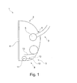
- the in FIG. 1 illustrated interior mirror 1 comprises a housing 2 and a mirror 3, which is fixed when properly mounted in the interior of a motor vehicle, for example, on a windshield of the motor vehicle.
- the housing 2 has a mirror foot receptacle 4 designed as an opening, through which the mirror base 3 protrudes into the interior of the mirror housing 2.
- the mirror base 3 has a ball head 5.
- the housing 2 is pivotally supported on the ball head 5 of the mirror 3.
- the mirror housing 2 has a mirror surface 6, which faces the driver when properly mounted in a motor vehicle and by means of which the driver can observe a located behind the motor vehicle rear traffic area.
- the interior mirror 1 also has a tilting device 7, from the in FIG. 1 only one designed as a rocker arm actuator 8 is shown.
- the actuating element 8 comprises a Kipphebelarm 10 and arranged at a first end of the Kipphebelarms 10 spherical area in which the actuating element is received on the housing 2 such that an axis of rotation 11 is formed.
- the actuating element 8 is arranged in an engagement region 9, which is formed as a recess of the housing 2.
- the axis of rotation 11 is oriented horizontally in the transverse direction to the direction of travel.
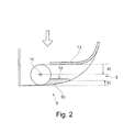
- the engagement area 9 is in FIG. 2 shown enlarged again.
- the housing 2 in the engagement region 9 has a protruding into the interior of the housing 2, with respect to the vertical direction of the upper edge region 13.
- the upper edge region 13 extends in the first tilting position of the actuating element 8 parallel to the Kipphebelarm 10.
- the upper edge region 13 and the Kipphebelarm 10 together form a substantially horizontally extending engagement opening.
- the axis of rotation 11 to the upper edge portion 13 at a distance a, which allows for an operator easy intervention.
- an underside of the Kipphebelarms 10, whose outer surface forms part of the outer contour of the inner mirror a distance b to a lower edge region of the housing 2.
- the actuating element 8 is not visible to the driver of the motor vehicle in the first tilting position.
- the actuator 8 is arranged with respect to an imaginary convex envelope of the housing 2 completely within the region of the envelope.
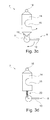
- FIG. 3a schematically shows the structure of a first embodiment of the tilting device 7.
- This comprises a holding element 14, which is arranged in the interior of the housing 2 and a ball head receptacle 15 has.
- the holding element 14 is received by means of the ball head receptacle 15 pivotally mounted on the ball head 5 of the mirror 3.
- the housing 2 is now on the one hand rotatably received in an upper pivot bearing 16 on the holding element 14, on the other hand, the housing 2 is rotatably connected in the axis of rotation 11 with the actuating element 8.
- the holding element 14 is held stationary on the mirror 3.
- the actuating element 8 in addition to the Kipphebelarm 10 on an actuating arm 17, which extends at an angle of about 120 ° to the actuating arm 10.
- An end of the actuating arm 17 remote from the axis of rotation 11 is received in a depression of the retaining element 14, so that a rotatable mounting of the actuating arm 17 on the retaining element 14 results.
- the Kipphebelarms 10 By turning the Kipphebelarms 10 by the driver of the motor vehicle in a clockwise direction now results in a pivoting movement of the actuating arm 17 also in a clockwise direction, as a result, the housing 2 in common with the rotation axis 11 performs a circular motion about the upper pivot bearing 16, also in a clockwise direction.
- pivoting the rocker arm 10 starting from the second tilt position in a counterclockwise direction, pivotal movement of the housing 2 about the upper pivot bearing 16 back to the first tilt position may be effected.
- FIG. 3b shows a second embodiment of the tilting device 7, wherein with respect to the first embodiment, the same elements are provided with the same reference numerals.
- the second embodiment differs essentially from the first embodiment in that, instead of an actuating arm 17, an actuating spring 18 acting on the retaining element is provided.
- Figure 3c shows a third embodiment in which the actuating arm 17 of the first embodiment and the actuating spring 18 of the second embodiment are replaced by a guide portion 19 which cooperates with a lower, guided end of the holding member 14.
- This in Figure 3c illustrated embodiment of the tilting device 7 thus provides essentially a kinematic reversal of in FIG. 3a shown first embodiment of the tilting device 7 is.
- FIG. 3d figure shows a fourth embodiment of the tilting device 7, wherein the actuating element 8 has a strut 20 which acts eccentrically on the actuating element 8 on the one hand and on the holding element 14 on the other.
- This embodiment has the advantage that, in contrast to the embodiments according to FIGS. 3a to 3c no pressure forces on the upper pivot bearing 16 and the axis of rotation 11 are exerted during the tilting process, since they are absorbed by the strut 20.
Landscapes
- Engineering & Computer Science (AREA)
- Multimedia (AREA)
- Mechanical Engineering (AREA)
- Rear-View Mirror Devices That Are Mounted On The Exterior Of The Vehicle (AREA)
Abstract
Description
- Die Erfindung betriff einen Innenspiegel für ein Kraftfahrzeug mit den Merkmalen gemäß des Oberbegriffs des Anspruchs 1.
- Aus der Praxis sind Innenspiegel für Kraftfahrzeuge bekannt, die, wenn sie für den erfindungsgemäßen Gebrauch in einem Kraftfahrzeug montiert sind, eine entgegen der Fahrtrichtung weisende Spiegelfläche umfassen. Um eine einfache Anpassung des Innenspiegels an unterschiedliche Sitzpositionen oder Körpergrößen des Fahrers des Kraftfahrzeugs zu ermöglichen, ist häufig vorgesehen, dass ein Gehäuse des Innenspiegels schwenkbar an einem beispielsweise an der Windschutzscheibe befestigten Spiegelfuß aufgenommen ist. Dabei ist häufig vorgesehen, dass die Spiegelfläche ortsfest zu dem Spiegelgehäuse angebracht ist. Um zu verhindern, dass der Fahrer des Kraftfahrzeugs in einer dunklen Umgebung von Lichtem hinter ihm fahrender Kraftfahrzeuge geblendet wird, ist es bekannt, an Innenspiegeln eine Kippvorrichtung vorzusehen, mittels der zumindest die Spiegelfläche zwischen einer ersten Kippstellung und einer zweiten Kippstellung verkippbar ist, wobei in einer der beiden Kippstellungen ein Reflektionsgrad der Spiegelfläche vermindert ist, um so ein Blenden des Fahrers zu vermeiden. Hierzu ist es bekannt, die Kippvorrichtung mit einem als Kipphebel ausgebildeten Betätigungselement zu versehen, dass durch eine Öffnung des Gehäuses des Innenspiegels hinaus geführt ist. Der Bereich außerhalb des Gehäuses des Innenspiegels bildet dann einen Eingriffsbereich für den Fahrer, der dort das Betätigungselement greifen und betätigen kann. Insbesondere ist es bekannt, einen Kipphebel bezüglich der betriebsbereit montierten Position des Innenspiegels unterhalb des Innenspiegels anzuordnen. Dies weist den Nachteil auf, dass der Kipphebel in dem Sichtbereich des Fahrers angeordnet ist und somit einerseits die Sicht stört, andererseits als ästhetisch nachteilig empfunden wird.
-
DE 10 2004 042 349 A1 beschreibt einen gattungsgemäßen Innenspiegel für ein Kraftfahrzeug, umfassend ein mehrteilig aufgebautes Gehäuse, dass schwenkbar an einem Spiegelfuß anordenbar ist. Das Gehäuse weist eine Spiegelfläche auf, die bei bestimmungsgemäßer Montage in einem Kraftfahrzeug den Fahrer des Kraftfahrzeugs zugewandt ist. In einer unteren Fläche des Gehäuses ist eine Öffnung vorgesehen, in der ein in vertikaler Richtung nach unten weisender Kipphebel aufgenommen ist, der außerhalb des Gehäuses in einen Eingriffsbereich für den Fahrer des Kraftfahrzeugs ragt. Durch verschwenken des Kipphebels ist das Gehäuse des Innenspiegels relativ zu dem Spiegelfuß verkippbar wobei die Spiegelfläche in einer der beiden Kipppositionen eine verminderte Lichtmenge reflektiert. -
DE 83 10 235 U1 beschreibt einen Innenspiegel für ein Kraftfahrzeug mit einem in vertikaler Richtung nach unten aus dem Gehäuse des Innenspiegels hinausgefiihrten Betätigungselement. Durch Drehen des Betätigungselements um eine vertikale Achse wird ein innerhalb des Spiegelgehäuses angeordnetes exzentrisches Element gegenüber einem Spiegelfuß verdreht, wobei das Spiegelgehäuse verkippt wird. - Es ist die Aufgabe der Erfindung, einen Innenspiegel für ein Kraftfahrzeug anzugeben, der ein einfaches Betätigen der Kippvorrichtung ermöglicht und der gegenüber den bekannten Innenspiegeln ästhetisch vorteilhaft ausgebildet ist.
- Diese Aufgabe wird erfindungsgemäß durch einen Innenspiegel für ein Kraftfahrzeug mit den Merkmalen des Anspruchs 1 gelöst.
- Der erfindungsgemäße Innenspiegel für ein Kraftfahrzeug umfasst ein Gehäuse, das vorzugsweise verschwenkbar an einem Spiegelfuß aufnehmbar ist, und eine Kippeinrichtung zum Verkippen zumindest einer Spiegelfläche des Innenspiegels zwischen wenigstens einer ersten Kippstellung und einer zweiten Kippstellung, wobei die Kippeinrichtung wenigstens ein Betätigungselement zum Verkippen der zumindest einen Spiegelfläche aufweist, wobei das Gehäuse wenigstens abschnittsweise einen Eingriffsbereich für einen Benutzer zum Betätigen des Betätigungselements begrenzt wobei der Eingriffsbereich bei zum bestimmungsgemäßen Gebrauch montiertem Innenspiegel in einem vom Fahrer des Kraftfahrzeugs abgewandten Bereich des Gehäuses angeordnet ist.
- Weiterhin wird die Aufgabe vorzugsweise dadurch gelöst, dass das der Eingriffsbereich wenigstens teilweise in einer Vertiefung des Gehäuses angeordnet ist.
- Zweckmäßig ist vorgesehen, dass das Gehäuse eine Öffnung zur Aufnahme des Betätigungselements aufweist.
- Vorzugsweise ist das Betätigungselement als ein um eine Drehachse drehbarer Kipphebel ausgebildet.
- Besonders bevorzugt ist dabei vorgesehen, dass das Gehäuse bei zum bestimmungsgemäßen Gebrauch montiertem Innenspiegel einen bezüglich der vertikalen Richtung oberen Rand des Eingriffsbereichs zumindest teilweise begrenzt, und dass die Drehachse bezüglich der vertikalen Richtung unterhalb des oberen Rands des Eingriffsbereichs angeordnet ist.
- Weiterhin erweist es sich als vorteilhaft, dass das Betätigungselement in wenigstens einer von erster Kippstellung und zweiter Kippstellung wenigstens abschnittsweise eine Außenkontur des Innenspiegels begrenzt, insbesondere das Gehäuse flächenbündig begrenzt und/oder in Richtung Gehäusemitte zurückspringt.
- Als besonders zweckmäßig erweist es sich, dass das Betätigungselement einen Griffbereich aufweist, und dass der Griffbereich in wenigstens einer von erster Kippstellung und zweiter Kippstellung wenigstens überwiegend einem von dem Gehäuse umschlossenen Innenbereich zugewandt ist.
- Darüber hinaus erweist es sich als vorteilhaft, dass das Betätigungselement in wenigstens einer von erster Kippstellung und zweiter Kippstellung vollständig in einem von einer konvexen Umhüllenden des Innenspiegels umschlossenen Bereich angeordnet ist.
- Vorzugsweise ist vorgesehen, dass das Betätigungselement drehbar an dem Gehäuse aufgenommen ist.
- Schließlich wird die Aufgabe in vorteilhafter Weiterbildung der Erfindung gelöst dadurch, dass das Gehäuse mittels der Kippeinrichtung relativ zu dem Spiegelfuß verkippbar ist.
- Die Erfindung beruht somit auf der überraschenden Erkenntnis, dass ein einfach zu bedienender Innenspiegel dadurch geschaffen werden kann, dass der Eingriffsbereich für einen Benutzer zum Betätigen des Betätigungselements einer Kippeinrichtung in einem vom Fahrer des Kraftfahrzeugs abgewandten Bereich des Gehäuses angeordnet ist. Hierdurch kann ein ästhetisch ansprechendes, nicht durch herausragende Hebel oder Ähnliches gestörtes Erscheinungsbild des Innenspiegel erreicht werden. Vorteilhaft kann der Innenspiegel dabei insgesamt eine Außenkontur aufweisen, die im Bereich des Blickfelds des Fahrers des Kraftfahrzeugs kontinuierlich ausgebildet ist, ohne dass in den Blickbereich ragende Hebel oder ähnliche Betätigungselemente sichtbar sind. Um zugleich eine einfache und sichere Betätigung der Kippvorrichtung durch den Fahrer des Kraftfahrzeugs zu ermöglichen, ist vorzugsweise eine Anordnung des Betätigungselements derart vorgesehen, dass der Eingriffsbereich in einer Vertiefung des Gehäuses angeordnet ist, so dass ein Fahrer insbesondere einen Greifbereich des Betätigungselements ohne Hinsehen sicher ertasten kann. Vorzugsweise ist dabei vorgesehen, dass insbesondere eine erste Kippstellung, in der das Betätigungselement für den Fahrer des Kraftfahrzeugs nicht sichtbar oder zumindest nicht als aus der Kontur des Innenspiegels herausragender Hebel sichtbar ist eine Kippstellung ist, in der der Spiegel eine hohe Reflektion aufweist. Hierbei handelt es sich somit um die übliche Gebrauchsstellung, beispielsweise für ein Fahren des Kraftfahrzeugs bei Tageslicht. Vorzugsweise ist in dieser Stellung vorgesehen, dass das Betätigungselement als ein Teil der Außenkontur des Innenspiegels ausbildet ist, insbesondere bündig mit dieser abschließt.
- Vorteilhaft ist das Betätigungselement drehbar an dem Gehäuse aufgenommen, wobei zweckmäßig innerhalb des Gehäuses Elemente der Kippeinrichtung vorgesehen sind, die ein Abstützen des Betätigungselements an einem dem Spiegelfuß zugeordneten Teil ermöglichen, um so ein Verkippen des gesamten Gehäuses gegenüber dem Spiegelfuß zu ermöglichen. Besonders bevorzugt ist vorgesehen, dass der Eingriffsbereich des Innenspiegels so ausgestaltet ist, dass bei für den bestimmungsgemäßen Gebrauch montiertem Innenspiegel ein oberer Bereich des Eingriffsbereichs von dem Gehäuse begrenzt wird. Eine zwischen Betätigungselement und Gehäuse ausgebildete Drehachse ist dabei unterhalb dieses oberen Randes angeordnet.
- Weitere Vorteile und Merkmale der Erfindung ergeben sich aus der nachstehenden Beschreibung bevorzugter Ausführungsbeispiele der Erfindung.
- Figur 1
- zeigt eine Querschnittansicht eines ersten Ausführungsbeispiels eines erfindungsgemäßen Innenspiegels.
- Figur 2
- zeigt vergrößert ein Detail aus
Figur 1 . - Figur 3a
- zeigt schematisch ein erstes Ausführungsbeispiel einer Kippeinrichtung für den Innenspiegel gemäß
Figur 1 . - Figur 3b
- zeigt ein zweites Ausführungsbeispiels einer Kippeinrichtung für den Innenspiegel gemäß
Figur 1 . - Figur 3c
- zeigt ein drittes Ausführungsbeispiel einer Kippeinrichtung für den Innenspiegel gemäß
Figur 1 . - Figur 3d
- zeigt ein viertes Ausführungsbeispiel einer Kippeinrichtung für den Innenspiegel gemäß
Figur 1 . - Der in
Figur 1 dargestellte Innenspiegel 1 umfasst ein Gehäuse 2 und einen Spiegelfuß 3, der bei bestimmungsgemäßer Montage im Innenraum eines Kraftfahrzeugs beispielsweise an einer Windschutzscheibe des Kraftfahrzeugs befestigt ist. Das Gehäuse 2 weist eine als Öffnung ausgebildete Spiegelfußaufnahme 4 auf, durch die der Spiegelfuß 3 in das Innere des Spiegelgehäuses 2 hineinragt. An einem von dem windschutzscheibenseitigen Ende des Spiegelfußes 3 entfernten Ende weist der Spiegelfuß 3 einen Kugelkopf 5 auf. Wie nachstehend noch unter Bezugnahme auf dieFiguren 3a bis 3d erläutert wird, ist das Gehäuse 2 schwenkbar an dem Kugelkopf 5 des Spiegelfußes 3 gehalten. - Das Spiegelgehäuse 2 weist eine Spiegelfläche 6 auf, die bei bestimmungsgemäßer Montage in einem Kraftfahrzeug dem Fahrer zugewandt ist und mittels der der Fahrer einen hinter dem Kraftfahrzeug befindlichen rückwärtigen Verkehrsraum beobachten kann. Der Innenspiegel 1 weist ferner eine Kippeinrichtung 7 auf, von der in
Figur 1 nur ein als Kipphebel ausgebildetes Betätigungselement 8 dargestellt ist. Das Betätigungselement 8 umfasst einen Kipphebelarm 10 und einen an einem ersten Ende des Kipphebelarms 10 angeordneten kugelförmigen Bereich, in dem das Betätigungselement derart an dem Gehäuse 2 aufgenommen ist, dass eine Drehachse 11 ausgebildet ist. Das Betätigungselement 8 ist dabei in einem Eingriffsbereich 9 angeordnet, der als Vertiefung des Gehäuses 2 ausgebildet ist. Die Drehachse 11 ist horizontal in Querrichtung zur Fahrtrichtung orientiert. - Ein Verrücken der Spiegelfläche 6 zwischen einer ersten, in
Figur 1 dargestellten Kippposition und einer zweiten Kippposition funktioniert dabei wie folgt: - Der Fahrer des Kraftfahrzeugs greift mit zumindest einem Finger in den Eingriffsbereich 9 des Innenspiegels, wobei ein Griffbereich 12 für ein Angreifen an das Betätigungselement 8 in einem Bereich des Kipphebelarms 10 angeordnet ist, der einem Innenbereich des Gehäuses 2 zugewandt ist. Durch Ziehen im Griffbereich 12 an dem Kipphebelarm 10 wird dieser um die Drehachse 11 in
Figur 1 im Uhrzeigersinn verschwenkt. Wie nachstehend noch unter Bezugnahme aufFigur 3a bis 3d beschrieben wird, führt dies zu einem Verschwenken des Spiegelgehäuses 2 gegenüber dem Spiegelfuß 3, so dass insbesondere die Spiegelfläche 6 aus der inFigur 1 dargestellten ersten Kippposition in eine dem gegenüber verschwenkte, zweite Kippposition verkippt wird. - Wie man in
Figur 1 gut erkennt, ist vorteilhaft in der dargestellten ersten Kippposition die Ausrichtung des Kipphebelarms 10 derart, dass er in einem unterem Bereich des Innenspiegels ein Teil der Außenkontur ausbildet, wodurch der Innenspiegel 1 insgesamt vorteilhaft eine gleichmäßige Außengestalt aufweist. Gleichwohl ist eine Betätigung des Betätigungselements 8 durch den Fahrer einfach möglich, da der Eingriffsbereich 9 leicht zu ertasten ist. - Der Eingriffsbereich 9 ist in
Figur 2 nochmals vergrößert dargestellt. Wie man hier insbesondere erkennt, weist das Gehäuse 2 in dem Eingriffsbereich 9 einen in das Innere des Gehäuses 2 ragenden, bezüglich der vertikalen Richtung oberen Randbereich 13 auf. Der obere Randbereich 13 erstreckt sich in der ersten Kippposition des Betätigungselements 8 dabei parallel zu dem Kipphebelarm 10. Somit bilden der obere Randbereich 13 und der Kipphebelarm 10 gemeinsam eine sich im Wesentlichen horizontal erstreckende Eingriffsöffnung aus. Wie man ferner erkennt, weist die Drehachse 11 zum oberen Randbereich 13 einen Abstand a auf, was für eine Bedienperson ein einfaches Eingreifen ermöglicht. Ferner weist eine Unterseite des Kipphebelarms 10, dessen Außenfläche einen Teil der Außenkontur des Innenspiegels bildet, einen Abstand b zu einem unteren Randbereich des Gehäuses 2 auf. Hierdurch ist das Betätigungselement 8 für den Fahrer des Kraftfahrzeugs in der ersten Kippposition nicht sichtbar. Entsprechend ist das Betätigungselement 8 bezüglich einer gedachten konvexen umhüllenden des Gehäuses 2 vollständig innerhalb des Bereichs der Umhüllenden angeordnet. -
Figur 3a zeigt schematisch den Aufbau eines ersten Ausführungsbeispiels der Kippeinrichtung 7. Diese umfasst ein Halteelement 14, dass im Inneren des Gehäuses 2 angeordnet ist und eine Kugelkopfaufnahme 15 aufweist. Das Halteelement 14 ist mittels der Kugelkopfaufnahme 15 schwenkbar auf dem Kugelkopf 5 des Spiegelfußes 3 aufgenommen. Das Gehäuse 2 ist nun einerseits in einem oberen Drehlager 16 drehbar an dem Halteelement 14 aufgenommen, andererseits ist das Gehäuse 2 in der Drehachse 11 drehbar mit dem Betätigungselement 8 verbunden. Zum Verkippen der Spiegelfläche 6 ist das Halteelement 14 ortsfest auf dem Spiegelfuß 3 gehalten. Wie man erkennt, weist das Betätigungselement 8 neben dem Kipphebelarm 10 einen Betätigungsarm 17 auf, der sich in einem Winkel von etwa 120° zu dem Betätigungsarm 10 erstreckt. Ein von der Drehachse 11 entferntes Ende des Betätigungsarms 17 ist in einer Mulde des Halteelements 14 aufgenommen, so dass sich eine drehbare Lagerung des Betätigungsarms 17 an dem Halteelement 14 ergibt. Durch Drehen des Kipphebelarms 10 durch den Fahrer des Kraftfahrzeugs im Uhrzeigersinn ergibt sich nun eine Schwenkbewegung des Betätigungsarms 17 ebenfalls im Uhrzeigersinn, wodurch im Ergebnis das Gehäuse 2 gemeinsam mit der Drehachse 11 eine Kreisbewegung um das oberer Drehlager 16, ebenfalls im Uhrzeigersinn, ausführt. Diese Bewegung endet in der zweiten Kippposition der Spiegelfläche 6. Umgekehrt kann durch Verschwenken des Kipphebelarms 10, ausgehend aus der zweiten Kippposition in eine Richtung entgegen des Uhrzeigersinns, eine Schwenkbewegung des Gehäuses 2 um das obere Drehlager 16 zurück in die erste Kippstellung bewirkt werden. -
Figur 3b zeigt ein zweites Ausführungsbeispiel der Kippeinrichtung 7, wobei gegenüber dem ersten Ausführungsbeispiel gleiche Elemente mit gleichen Bezugszeichen versehen sind. Das zweite Ausführungsbeispiel unterscheidet sich im Wesentlichen von dem ersten Ausführungsbeispiel dadurch, dass statt eines Betätigungsarms 17 eine an dem Halteelement angreifende Betätigungsfeder 18 vorgesehen ist. -
Figur 3c zeigt ein drittes Ausführungsbeispiel, bei dem der Betätigungsarm 17 des ersten Ausführungsbeispiels bzw. die Betätigungsfeder 18 des zweiten Ausführungsbeispiels durch einen Führungsbereich 19 ersetzt sind, der mit einem unteren, geführten Ende des Halteelements 14 zusammen wirkt. Das inFigur 3c dargestellte Ausführungsbeispiel der Kippeinrichtung 7 stellt somit im Wesentlichen eine kinematische Umkehr des inFigur 3a dargestellten ersten Ausführungsbeispiels der Kippeinrichtung 7 dar. -
Figur 3d zeigt ein viertes Ausführungsbeispiel der Kippeinrichtung 7, bei der das Betätigungselement 8 ein Federbein 20 aufweist, das exzentrisch an dem Betätigungselement 8 einerseits und an dem Halteelement 14 andererseits angreift. Diese Ausgestaltung hat den Vorteil, dass im Gegensatz zu den Ausführungsbeispielen gemäßFiguren 3a bis 3c während des Kippvorgangs keine Druckkräfte auf das obere Drehlager 16 und die Drehachse 11 ausgeübt werden, da diese durch das Federbein 20 aufgenommen werden.Bezugszeichenliste 1 Innenspiegel 2 Gehäuse 3 Spiegelfuß 4 Spiegelfußaufnahme 5 Kugelkopf 6 Spiegelfläche 7 Kippeinrichtung 8 Betätigungselement 9 Eingriffsbereich 10 Kipphebelarm 11 Drehachse 12 Griffbereich 13 oberer Randbereich 14 Halteelement 15 Kugelkopfaufnahme 16 oberes Drehlager 17 Betätigungsarm 18 Betätigungsfeder 19 Führungsbereich 20 Federbein
Claims (10)
- Innenspiegel (1) für ein Kraftfahrzeug, umfassend ein Gehäuse (2), das vorzugsweise verschwenkbar an einem Spiegelfuß (3) aufnehmbar ist, und eine Kippeinrichtung (7) zum Verkippen zumindest einer Spiegelfläche (6) des Innenspiegels (1) zwischen wenigstens einer ersten Kippstellung und einer zweiten Kippstellung, wobei die Kippeinrichtung (7) wenigstens ein Betätigungselement (8) zum Verkippen der zumindest einen Spiegelfläche (6) aufweist, wobei das Gehäuse (2) wenigstens abschnittsweise einen Eingriffsbereich (9) für einen Benutzer zum Betätigen des Betätigungselements (8) begrenzt, dadurch gekennzeichnet, dass der Eingriffsbereich (9) bei zum bestimmungsgemäßen Gebrauch montiertem Innenspiegel (1) in einem vom Fahrer des Kraftfahrzeugs abgewandten Bereich des Gehäuses (2) angeordnet ist.
- Innenspiegel (1) nach Anspruch 1, dadurch gekennzeichnet, dass
der Eingriffsbereich (9) wenigstens teilweise in einer Vertiefung des Gehäuses (2) angeordnet ist. - Innenspiegel (1) nach Anspruch 1 oder 2, dadurch gekennzeichnet, dass das Gehäuse (2) eine Öffnung zur Aufnahme des Betätigungselements (8) aufweist.
- Innenspiegel (1) nach einem der vorangehenden Ansprüche, dadurch gekennzeichnet, dass das Betätigungselement (8) als ein um eine Drehachse (11) drehbarer Kipphebel ausgebildet ist.
- Innenspiegel (1) nach einem der vorangehenden Ansprüche, dadurch gekennzeichnet, dass das Gehäuse (2) bei zum bestimmungsgemäßen Gebrauch montiertem Innenspiegel (1) einen bezüglich der vertikalen Richtung oberen Rand (13) des Eingriffsbereichs (9) zumindest teilweise begrenzt, und dass die Drehachse (11) bezüglich der vertikalen Richtung unterhalb des oberen Rands (13) des Eingriffsbereichs (9) angeordnet ist.
- Innenspiegel (1) nach einem der vorangehenden Ansprüche, dadurch gekennzeichnet, dass das Betätigungselement (8) in wenigstens einer von erster Kippstellung und zweiter Kippstellung wenigstens abschnittsweise eine Außenkontur des Innenspiegels (1) begrenzt, wobei insbesondere das Betätigungselement (8) das Gehäuse flächenbündig begrenzt und/oder in Richtung Gehäusemitte zurückspringt.
- Innenspiegel (1) nach einem der vorangehenden Ansprüche, dadurch gekennzeichnet, dass das Betätigungselement (8) einen Griffbereich (12) aufweist, und dass der Griffbereich (12) in wenigstens einer von erster Kippstellung und zweiter Kippstellung wenigstens überwiegend einem von dem Gehäuse (2) umschlossenen Innenbereich zugewandt ist.
- Innenspiegel (1) nach einem der vorangehenden Ansprüche, dadurch gekennzeichnet, dass das Betätigungselement (8) in wenigstens einer von erster Kippstellung und zweiter Kippstellung vollständig in einem von einer konvexen Umhüllenden des Innenspiegels (1) umschlossenen Bereich angeordnet ist.
- Innenspiegel (1) nach einem der vorangehenden Ansprüche, dadurch gekennzeichnet, dass das Betätigungselement (8) drehbar an dem Gehäuse (2) aufgenommen ist.
- Innenspiegel (1) nach einem der vorangehenden Ansprüche, dadurch gekennzeichnet, dass das Gehäuse (2) mittels der Kippeinrichtung (7) relativ zu dem Spiegelfuß (3) verkippbar ist.
Priority Applications (1)
| Application Number | Priority Date | Filing Date | Title |
|---|---|---|---|
| EP13162004.9A EP2786900B1 (de) | 2013-04-02 | 2013-04-02 | Innenspiegel für ein Kraftfahrzeug |
Applications Claiming Priority (1)
| Application Number | Priority Date | Filing Date | Title |
|---|---|---|---|
| EP13162004.9A EP2786900B1 (de) | 2013-04-02 | 2013-04-02 | Innenspiegel für ein Kraftfahrzeug |
Publications (2)
| Publication Number | Publication Date |
|---|---|
| EP2786900A1 true EP2786900A1 (de) | 2014-10-08 |
| EP2786900B1 EP2786900B1 (de) | 2014-11-12 |
Family
ID=48013858
Family Applications (1)
| Application Number | Title | Priority Date | Filing Date |
|---|---|---|---|
| EP13162004.9A Active EP2786900B1 (de) | 2013-04-02 | 2013-04-02 | Innenspiegel für ein Kraftfahrzeug |
Country Status (1)
| Country | Link |
|---|---|
| EP (1) | EP2786900B1 (de) |
Citations (9)
| Publication number | Priority date | Publication date | Assignee | Title |
|---|---|---|---|---|
| US3427094A (en) * | 1966-10-17 | 1969-02-11 | Arvin Ind Inc | Rearview mirror and adjusting mechanism therefor |
| US3472580A (en) * | 1967-11-20 | 1969-10-14 | Libbey Owens Ford Co | Multiple position rear view mirror with unitary plastic hinge bracket |
| US3586422A (en) * | 1968-10-18 | 1971-06-22 | Ichikoh Industries Ltd | Adjustable rear view mirror |
| FR2063750A5 (de) * | 1969-10-30 | 1971-07-09 | Cipa | |
| DE8310235U1 (de) | 1983-10-27 | Hohe Kg, 6981 Collenberg | Kippbarer Rückblick-Innenspiegel für Fahrzeuge | |
| US5327288A (en) * | 1991-09-13 | 1994-07-05 | Donnelly Corporation | Reduced vibration day/night rearview mirror assembly |
| EP1275559A1 (de) * | 2001-07-13 | 2003-01-15 | Murakami Corporation | Innenrückblickspiegel |
| EP1325839A1 (de) * | 2001-12-26 | 2003-07-09 | Ichikoh Industries, Ltd. | Kraftfahrzeuginnenrückspiegel |
| DE102004042349A1 (de) | 2004-09-01 | 2006-03-16 | Magna Reflex Holding Gmbh | Innenspiegel für Kraftfahrzeuge |
-
2013
- 2013-04-02 EP EP13162004.9A patent/EP2786900B1/de active Active
Patent Citations (9)
| Publication number | Priority date | Publication date | Assignee | Title |
|---|---|---|---|---|
| DE8310235U1 (de) | 1983-10-27 | Hohe Kg, 6981 Collenberg | Kippbarer Rückblick-Innenspiegel für Fahrzeuge | |
| US3427094A (en) * | 1966-10-17 | 1969-02-11 | Arvin Ind Inc | Rearview mirror and adjusting mechanism therefor |
| US3472580A (en) * | 1967-11-20 | 1969-10-14 | Libbey Owens Ford Co | Multiple position rear view mirror with unitary plastic hinge bracket |
| US3586422A (en) * | 1968-10-18 | 1971-06-22 | Ichikoh Industries Ltd | Adjustable rear view mirror |
| FR2063750A5 (de) * | 1969-10-30 | 1971-07-09 | Cipa | |
| US5327288A (en) * | 1991-09-13 | 1994-07-05 | Donnelly Corporation | Reduced vibration day/night rearview mirror assembly |
| EP1275559A1 (de) * | 2001-07-13 | 2003-01-15 | Murakami Corporation | Innenrückblickspiegel |
| EP1325839A1 (de) * | 2001-12-26 | 2003-07-09 | Ichikoh Industries, Ltd. | Kraftfahrzeuginnenrückspiegel |
| DE102004042349A1 (de) | 2004-09-01 | 2006-03-16 | Magna Reflex Holding Gmbh | Innenspiegel für Kraftfahrzeuge |
Also Published As
| Publication number | Publication date |
|---|---|
| EP2786900B1 (de) | 2014-11-12 |
Similar Documents
| Publication | Publication Date | Title |
|---|---|---|
| EP2073653B1 (de) | Kopfschutzkombination | |
| DE69514933T2 (de) | Verstellbarer rückspiegel für ein lastkraftwagen | |
| DE10159919B4 (de) | Verkleidungsteil mit ausklappbarem Bildschirm | |
| DE4331884B4 (de) | Abdeckeinrichtung für einen Kosmetikspiegel | |
| EP1725429B1 (de) | Vorrichtung zur winkelverstellung einer um eine drehachse drehbar vorgesehenen komponente, insbesondere einer armlehne in einem fahrzeug | |
| EP1945485B1 (de) | Wischeranlage für frontscheiben an kraftfahrzeugen | |
| DE4407108C2 (de) | Fahrzeugscheinwerfer mit einer verstellbaren Blendenanordnung | |
| EP3164292A1 (de) | ANORDNUNG ZUM FREIGEBEN UND SCHLIEßEN EINER ÖFFNUNG IN EINEM INNENAUSSTATTUNGSTEIL EINES FAHRZEUGS | |
| WO2007131761A1 (de) | Sitzanordnung für ein kraftfahrzeug | |
| DE102005050222B4 (de) | Gelenkbeschlag für ein Rückenlehnengelenk eines Kraftfahrzeugsitzes | |
| EP0337364B1 (de) | Abklappbarer Aussenspiegel für Fahrzeuge | |
| EP2786900B1 (de) | Innenspiegel für ein Kraftfahrzeug | |
| DE10224835B4 (de) | Sonnenblende für den Innenraum eines Kraftfahrzeugs | |
| EP1359054A2 (de) | Laderaumabdeckung mit einer Durchgriffsöffnung | |
| DE19915469B4 (de) | Armlehne für eine Fahrzeugmittelkonsole | |
| DE102007033797B4 (de) | Fahrzeug-Overheadkonsolenanordnung | |
| DE102016211666B4 (de) | Scheibenwischersystem | |
| DE2037101A1 (de) | Fernverstellbarer und abklappbarer Außen rückblickspiegel, insbesondere für Personen kraftwagen | |
| DE102012015344A1 (de) | Lehnenstruktur für einen Fahrzeugsitz mit neigungsverstellbarem Lehnenkopf | |
| DE102005060709B4 (de) | Bremse für das Ringscharnier an einer Kraftfahrzeugtür | |
| DE112007001634B4 (de) | Scharnier zum Befestigen von Innenraumteilen von Kraftfahrzeugen | |
| DE3718432C2 (de) | Aussenrückblickspiegel mit einem abklappbaren Gehäuse für Kraftfahrzeuge | |
| DE102006037344B4 (de) | Sitzanordnung für ein Kraftfahrzeug | |
| DE60121073T2 (de) | Aussenrückspiegel | |
| DE102013014179A1 (de) | Türinnenbetätigung für ein Kraftfahrzeug und ein Kraftfahrzeug |
Legal Events
| Date | Code | Title | Description |
|---|---|---|---|
| GRAP | Despatch of communication of intention to grant a patent |
Free format text: ORIGINAL CODE: EPIDOSNIGR1 |
|
| GRAS | Grant fee paid |
Free format text: ORIGINAL CODE: EPIDOSNIGR3 |
|
| PUAI | Public reference made under article 153(3) epc to a published international application that has entered the european phase |
Free format text: ORIGINAL CODE: 0009012 |
|
| 17P | Request for examination filed |
Effective date: 20140225 |
|
| AK | Designated contracting states |
Kind code of ref document: A1 Designated state(s): AL AT BE BG CH CY CZ DE DK EE ES FI FR GB GR HR HU IE IS IT LI LT LU LV MC MK MT NL NO PL PT RO RS SE SI SK SM TR |
|
| GRAA | (expected) grant |
Free format text: ORIGINAL CODE: 0009210 |
|
| AK | Designated contracting states |
Kind code of ref document: B1 Designated state(s): AL AT BE BG CH CY CZ DE DK EE ES FI FR GB GR HR HU IE IS IT LI LT LU LV MC MK MT NL NO PL PT RO RS SE SI SK SM TR |
|
| REG | Reference to a national code |
Ref country code: GB Ref legal event code: FG4D Free format text: NOT ENGLISH |
|
| REG | Reference to a national code |
Ref country code: CH Ref legal event code: EP |
|
| REG | Reference to a national code |
Ref country code: AT Ref legal event code: REF Ref document number: 695526 Country of ref document: AT Kind code of ref document: T Effective date: 20141115 |
|
| REG | Reference to a national code |
Ref country code: IE Ref legal event code: FG4D Free format text: LANGUAGE OF EP DOCUMENT: GERMAN |
|
| REG | Reference to a national code |
Ref country code: DE Ref legal event code: R096 Ref document number: 502013000170 Country of ref document: DE Effective date: 20141231 |
|
| REG | Reference to a national code |
Ref country code: NL Ref legal event code: VDEP Effective date: 20141112 |
|
| PG25 | Lapsed in a contracting state [announced via postgrant information from national office to epo] |
Ref country code: IS Free format text: LAPSE BECAUSE OF FAILURE TO SUBMIT A TRANSLATION OF THE DESCRIPTION OR TO PAY THE FEE WITHIN THE PRESCRIBED TIME-LIMIT Effective date: 20150312 Ref country code: FI Free format text: LAPSE BECAUSE OF FAILURE TO SUBMIT A TRANSLATION OF THE DESCRIPTION OR TO PAY THE FEE WITHIN THE PRESCRIBED TIME-LIMIT Effective date: 20141112 Ref country code: LT Free format text: LAPSE BECAUSE OF FAILURE TO SUBMIT A TRANSLATION OF THE DESCRIPTION OR TO PAY THE FEE WITHIN THE PRESCRIBED TIME-LIMIT Effective date: 20141112 Ref country code: NL Free format text: LAPSE BECAUSE OF FAILURE TO SUBMIT A TRANSLATION OF THE DESCRIPTION OR TO PAY THE FEE WITHIN THE PRESCRIBED TIME-LIMIT Effective date: 20141112 Ref country code: PT Free format text: LAPSE BECAUSE OF FAILURE TO SUBMIT A TRANSLATION OF THE DESCRIPTION OR TO PAY THE FEE WITHIN THE PRESCRIBED TIME-LIMIT Effective date: 20150312 Ref country code: ES Free format text: LAPSE BECAUSE OF FAILURE TO SUBMIT A TRANSLATION OF THE DESCRIPTION OR TO PAY THE FEE WITHIN THE PRESCRIBED TIME-LIMIT Effective date: 20141112 Ref country code: NO Free format text: LAPSE BECAUSE OF FAILURE TO SUBMIT A TRANSLATION OF THE DESCRIPTION OR TO PAY THE FEE WITHIN THE PRESCRIBED TIME-LIMIT Effective date: 20150212 |
|
| PG25 | Lapsed in a contracting state [announced via postgrant information from national office to epo] |
Ref country code: HR Free format text: LAPSE BECAUSE OF FAILURE TO SUBMIT A TRANSLATION OF THE DESCRIPTION OR TO PAY THE FEE WITHIN THE PRESCRIBED TIME-LIMIT Effective date: 20141112 Ref country code: CY Free format text: LAPSE BECAUSE OF FAILURE TO SUBMIT A TRANSLATION OF THE DESCRIPTION OR TO PAY THE FEE WITHIN THE PRESCRIBED TIME-LIMIT Effective date: 20141112 Ref country code: SE Free format text: LAPSE BECAUSE OF FAILURE TO SUBMIT A TRANSLATION OF THE DESCRIPTION OR TO PAY THE FEE WITHIN THE PRESCRIBED TIME-LIMIT Effective date: 20141112 Ref country code: GR Free format text: LAPSE BECAUSE OF FAILURE TO SUBMIT A TRANSLATION OF THE DESCRIPTION OR TO PAY THE FEE WITHIN THE PRESCRIBED TIME-LIMIT Effective date: 20150213 Ref country code: RS Free format text: LAPSE BECAUSE OF FAILURE TO SUBMIT A TRANSLATION OF THE DESCRIPTION OR TO PAY THE FEE WITHIN THE PRESCRIBED TIME-LIMIT Effective date: 20141112 Ref country code: LV Free format text: LAPSE BECAUSE OF FAILURE TO SUBMIT A TRANSLATION OF THE DESCRIPTION OR TO PAY THE FEE WITHIN THE PRESCRIBED TIME-LIMIT Effective date: 20141112 Ref country code: PL Free format text: LAPSE BECAUSE OF FAILURE TO SUBMIT A TRANSLATION OF THE DESCRIPTION OR TO PAY THE FEE WITHIN THE PRESCRIBED TIME-LIMIT Effective date: 20141112 |
|
| PG25 | Lapsed in a contracting state [announced via postgrant information from national office to epo] |
Ref country code: SK Free format text: LAPSE BECAUSE OF FAILURE TO SUBMIT A TRANSLATION OF THE DESCRIPTION OR TO PAY THE FEE WITHIN THE PRESCRIBED TIME-LIMIT Effective date: 20141112 Ref country code: RO Free format text: LAPSE BECAUSE OF FAILURE TO SUBMIT A TRANSLATION OF THE DESCRIPTION OR TO PAY THE FEE WITHIN THE PRESCRIBED TIME-LIMIT Effective date: 20141112 Ref country code: CZ Free format text: LAPSE BECAUSE OF FAILURE TO SUBMIT A TRANSLATION OF THE DESCRIPTION OR TO PAY THE FEE WITHIN THE PRESCRIBED TIME-LIMIT Effective date: 20141112 Ref country code: EE Free format text: LAPSE BECAUSE OF FAILURE TO SUBMIT A TRANSLATION OF THE DESCRIPTION OR TO PAY THE FEE WITHIN THE PRESCRIBED TIME-LIMIT Effective date: 20141112 Ref country code: DK Free format text: LAPSE BECAUSE OF FAILURE TO SUBMIT A TRANSLATION OF THE DESCRIPTION OR TO PAY THE FEE WITHIN THE PRESCRIBED TIME-LIMIT Effective date: 20141112 |
|
| REG | Reference to a national code |
Ref country code: DE Ref legal event code: R097 Ref document number: 502013000170 Country of ref document: DE |
|
| PLBE | No opposition filed within time limit |
Free format text: ORIGINAL CODE: 0009261 |
|
| STAA | Information on the status of an ep patent application or granted ep patent |
Free format text: STATUS: NO OPPOSITION FILED WITHIN TIME LIMIT |
|
| 26N | No opposition filed |
Effective date: 20150813 |
|
| PG25 | Lapsed in a contracting state [announced via postgrant information from national office to epo] |
Ref country code: MC Free format text: LAPSE BECAUSE OF FAILURE TO SUBMIT A TRANSLATION OF THE DESCRIPTION OR TO PAY THE FEE WITHIN THE PRESCRIBED TIME-LIMIT Effective date: 20141112 Ref country code: LU Free format text: LAPSE BECAUSE OF FAILURE TO SUBMIT A TRANSLATION OF THE DESCRIPTION OR TO PAY THE FEE WITHIN THE PRESCRIBED TIME-LIMIT Effective date: 20150402 |
|
| PG25 | Lapsed in a contracting state [announced via postgrant information from national office to epo] |
Ref country code: IT Free format text: LAPSE BECAUSE OF FAILURE TO SUBMIT A TRANSLATION OF THE DESCRIPTION OR TO PAY THE FEE WITHIN THE PRESCRIBED TIME-LIMIT Effective date: 20141112 |
|
| REG | Reference to a national code |
Ref country code: IE Ref legal event code: MM4A |
|
| PG25 | Lapsed in a contracting state [announced via postgrant information from national office to epo] |
Ref country code: SI Free format text: LAPSE BECAUSE OF FAILURE TO SUBMIT A TRANSLATION OF THE DESCRIPTION OR TO PAY THE FEE WITHIN THE PRESCRIBED TIME-LIMIT Effective date: 20141112 |
|
| REG | Reference to a national code |
Ref country code: FR Ref legal event code: PLFP Year of fee payment: 4 |
|
| PG25 | Lapsed in a contracting state [announced via postgrant information from national office to epo] |
Ref country code: IE Free format text: LAPSE BECAUSE OF NON-PAYMENT OF DUE FEES Effective date: 20150402 |
|
| REG | Reference to a national code |
Ref country code: CH Ref legal event code: PL |
|
| PG25 | Lapsed in a contracting state [announced via postgrant information from national office to epo] |
Ref country code: MT Free format text: LAPSE BECAUSE OF FAILURE TO SUBMIT A TRANSLATION OF THE DESCRIPTION OR TO PAY THE FEE WITHIN THE PRESCRIBED TIME-LIMIT Effective date: 20141112 |
|
| PG25 | Lapsed in a contracting state [announced via postgrant information from national office to epo] |
Ref country code: CH Free format text: LAPSE BECAUSE OF NON-PAYMENT OF DUE FEES Effective date: 20160430 Ref country code: LI Free format text: LAPSE BECAUSE OF NON-PAYMENT OF DUE FEES Effective date: 20160430 |
|
| REG | Reference to a national code |
Ref country code: FR Ref legal event code: PLFP Year of fee payment: 5 |
|
| PG25 | Lapsed in a contracting state [announced via postgrant information from national office to epo] |
Ref country code: HU Free format text: LAPSE BECAUSE OF FAILURE TO SUBMIT A TRANSLATION OF THE DESCRIPTION OR TO PAY THE FEE WITHIN THE PRESCRIBED TIME-LIMIT; INVALID AB INITIO Effective date: 20130402 Ref country code: BG Free format text: LAPSE BECAUSE OF FAILURE TO SUBMIT A TRANSLATION OF THE DESCRIPTION OR TO PAY THE FEE WITHIN THE PRESCRIBED TIME-LIMIT Effective date: 20141112 |
|
| PG25 | Lapsed in a contracting state [announced via postgrant information from national office to epo] |
Ref country code: BE Free format text: LAPSE BECAUSE OF NON-PAYMENT OF DUE FEES Effective date: 20150430 |
|
| PG25 | Lapsed in a contracting state [announced via postgrant information from national office to epo] |
Ref country code: TR Free format text: LAPSE BECAUSE OF FAILURE TO SUBMIT A TRANSLATION OF THE DESCRIPTION OR TO PAY THE FEE WITHIN THE PRESCRIBED TIME-LIMIT Effective date: 20141112 |
|
| REG | Reference to a national code |
Ref country code: FR Ref legal event code: PLFP Year of fee payment: 6 |
|
| PG25 | Lapsed in a contracting state [announced via postgrant information from national office to epo] |
Ref country code: SM Free format text: LAPSE BECAUSE OF FAILURE TO SUBMIT A TRANSLATION OF THE DESCRIPTION OR TO PAY THE FEE WITHIN THE PRESCRIBED TIME-LIMIT Effective date: 20141112 |
|
| PG25 | Lapsed in a contracting state [announced via postgrant information from national office to epo] |
Ref country code: MK Free format text: LAPSE BECAUSE OF FAILURE TO SUBMIT A TRANSLATION OF THE DESCRIPTION OR TO PAY THE FEE WITHIN THE PRESCRIBED TIME-LIMIT Effective date: 20141112 |
|
| PG25 | Lapsed in a contracting state [announced via postgrant information from national office to epo] |
Ref country code: AL Free format text: LAPSE BECAUSE OF FAILURE TO SUBMIT A TRANSLATION OF THE DESCRIPTION OR TO PAY THE FEE WITHIN THE PRESCRIBED TIME-LIMIT Effective date: 20141112 |
|
| REG | Reference to a national code |
Ref country code: AT Ref legal event code: MM01 Ref document number: 695526 Country of ref document: AT Kind code of ref document: T Effective date: 20180402 |
|
| PG25 | Lapsed in a contracting state [announced via postgrant information from national office to epo] |
Ref country code: AT Free format text: LAPSE BECAUSE OF NON-PAYMENT OF DUE FEES Effective date: 20180402 |
|
| REG | Reference to a national code |
Ref country code: DE Ref legal event code: R084 Ref document number: 502013000170 Country of ref document: DE |
|
| P01 | Opt-out of the competence of the unified patent court (upc) registered |
Effective date: 20230616 |
|
| PGFP | Annual fee paid to national office [announced via postgrant information from national office to epo] |
Ref country code: DE Payment date: 20250417 Year of fee payment: 13 |
|
| PGFP | Annual fee paid to national office [announced via postgrant information from national office to epo] |
Ref country code: GB Payment date: 20250423 Year of fee payment: 13 |
|
| PGFP | Annual fee paid to national office [announced via postgrant information from national office to epo] |
Ref country code: FR Payment date: 20250428 Year of fee payment: 13 |