EP2786827A1 - Bonded component - Google Patents
Bonded component Download PDFInfo
- Publication number
- EP2786827A1 EP2786827A1 EP12853153.0A EP12853153A EP2786827A1 EP 2786827 A1 EP2786827 A1 EP 2786827A1 EP 12853153 A EP12853153 A EP 12853153A EP 2786827 A1 EP2786827 A1 EP 2786827A1
- Authority
- EP
- European Patent Office
- Prior art keywords
- shaft
- carbide
- tial
- steel
- filler metal
- Prior art date
- Legal status (The legal status is an assumption and is not a legal conclusion. Google has not performed a legal analysis and makes no representation as to the accuracy of the status listed.)
- Granted
Links
Images



Classifications
-
- B—PERFORMING OPERATIONS; TRANSPORTING
- B23—MACHINE TOOLS; METAL-WORKING NOT OTHERWISE PROVIDED FOR
- B23K—SOLDERING OR UNSOLDERING; WELDING; CLADDING OR PLATING BY SOLDERING OR WELDING; CUTTING BY APPLYING HEAT LOCALLY, e.g. FLAME CUTTING; WORKING BY LASER BEAM
- B23K1/00—Soldering, e.g. brazing, or unsoldering
- B23K1/19—Soldering, e.g. brazing, or unsoldering taking account of the properties of the materials to be soldered
-
- B—PERFORMING OPERATIONS; TRANSPORTING
- B23—MACHINE TOOLS; METAL-WORKING NOT OTHERWISE PROVIDED FOR
- B23K—SOLDERING OR UNSOLDERING; WELDING; CLADDING OR PLATING BY SOLDERING OR WELDING; CUTTING BY APPLYING HEAT LOCALLY, e.g. FLAME CUTTING; WORKING BY LASER BEAM
- B23K1/00—Soldering, e.g. brazing, or unsoldering
- B23K1/0008—Soldering, e.g. brazing, or unsoldering specially adapted for particular articles or work
- B23K1/0018—Brazing of turbine parts
-
- B—PERFORMING OPERATIONS; TRANSPORTING
- B23—MACHINE TOOLS; METAL-WORKING NOT OTHERWISE PROVIDED FOR
- B23K—SOLDERING OR UNSOLDERING; WELDING; CLADDING OR PLATING BY SOLDERING OR WELDING; CUTTING BY APPLYING HEAT LOCALLY, e.g. FLAME CUTTING; WORKING BY LASER BEAM
- B23K35/00—Rods, electrodes, materials, or media, for use in soldering, welding, or cutting
- B23K35/001—Interlayers, transition pieces for metallurgical bonding of workpieces
- B23K35/002—Interlayers, transition pieces for metallurgical bonding of workpieces at least one of the workpieces being of light metal
-
- B—PERFORMING OPERATIONS; TRANSPORTING
- B23—MACHINE TOOLS; METAL-WORKING NOT OTHERWISE PROVIDED FOR
- B23K—SOLDERING OR UNSOLDERING; WELDING; CLADDING OR PLATING BY SOLDERING OR WELDING; CUTTING BY APPLYING HEAT LOCALLY, e.g. FLAME CUTTING; WORKING BY LASER BEAM
- B23K35/00—Rods, electrodes, materials, or media, for use in soldering, welding, or cutting
- B23K35/001—Interlayers, transition pieces for metallurgical bonding of workpieces
- B23K35/004—Interlayers, transition pieces for metallurgical bonding of workpieces at least one of the workpieces being of a metal of the iron group
-
- B—PERFORMING OPERATIONS; TRANSPORTING
- B23—MACHINE TOOLS; METAL-WORKING NOT OTHERWISE PROVIDED FOR
- B23K—SOLDERING OR UNSOLDERING; WELDING; CLADDING OR PLATING BY SOLDERING OR WELDING; CUTTING BY APPLYING HEAT LOCALLY, e.g. FLAME CUTTING; WORKING BY LASER BEAM
- B23K35/00—Rods, electrodes, materials, or media, for use in soldering, welding, or cutting
- B23K35/001—Interlayers, transition pieces for metallurgical bonding of workpieces
- B23K35/005—Interlayers, transition pieces for metallurgical bonding of workpieces at least one of the workpieces being of a refractory metal
-
- B—PERFORMING OPERATIONS; TRANSPORTING
- B23—MACHINE TOOLS; METAL-WORKING NOT OTHERWISE PROVIDED FOR
- B23K—SOLDERING OR UNSOLDERING; WELDING; CLADDING OR PLATING BY SOLDERING OR WELDING; CUTTING BY APPLYING HEAT LOCALLY, e.g. FLAME CUTTING; WORKING BY LASER BEAM
- B23K35/00—Rods, electrodes, materials, or media, for use in soldering, welding, or cutting
- B23K35/02—Rods, electrodes, materials, or media, for use in soldering, welding, or cutting characterised by mechanical features, e.g. shape
- B23K35/0222—Rods, electrodes, materials, or media, for use in soldering, welding, or cutting characterised by mechanical features, e.g. shape for use in soldering or brazing
-
- B—PERFORMING OPERATIONS; TRANSPORTING
- B23—MACHINE TOOLS; METAL-WORKING NOT OTHERWISE PROVIDED FOR
- B23K—SOLDERING OR UNSOLDERING; WELDING; CLADDING OR PLATING BY SOLDERING OR WELDING; CUTTING BY APPLYING HEAT LOCALLY, e.g. FLAME CUTTING; WORKING BY LASER BEAM
- B23K35/00—Rods, electrodes, materials, or media, for use in soldering, welding, or cutting
- B23K35/22—Rods, electrodes, materials, or media, for use in soldering, welding, or cutting characterised by the composition or nature of the material
- B23K35/24—Selection of soldering or welding materials proper
- B23K35/30—Selection of soldering or welding materials proper with the principal constituent melting at less than 1550°C
- B23K35/3033—Ni as the principal constituent
-
- B—PERFORMING OPERATIONS; TRANSPORTING
- B32—LAYERED PRODUCTS
- B32B—LAYERED PRODUCTS, i.e. PRODUCTS BUILT-UP OF STRATA OF FLAT OR NON-FLAT, e.g. CELLULAR OR HONEYCOMB, FORM
- B32B15/00—Layered products comprising a layer of metal
- B32B15/01—Layered products comprising a layer of metal all layers being exclusively metallic
- B32B15/013—Layered products comprising a layer of metal all layers being exclusively metallic one layer being formed of an iron alloy or steel, another layer being formed of a metal other than iron or aluminium
-
- C—CHEMISTRY; METALLURGY
- C22—METALLURGY; FERROUS OR NON-FERROUS ALLOYS; TREATMENT OF ALLOYS OR NON-FERROUS METALS
- C22C—ALLOYS
- C22C14/00—Alloys based on titanium
-
- C—CHEMISTRY; METALLURGY
- C22—METALLURGY; FERROUS OR NON-FERROUS ALLOYS; TREATMENT OF ALLOYS OR NON-FERROUS METALS
- C22C—ALLOYS
- C22C38/00—Ferrous alloys, e.g. steel alloys
-
- C—CHEMISTRY; METALLURGY
- C22—METALLURGY; FERROUS OR NON-FERROUS ALLOYS; TREATMENT OF ALLOYS OR NON-FERROUS METALS
- C22C—ALLOYS
- C22C38/00—Ferrous alloys, e.g. steel alloys
- C22C38/18—Ferrous alloys, e.g. steel alloys containing chromium
-
- C—CHEMISTRY; METALLURGY
- C22—METALLURGY; FERROUS OR NON-FERROUS ALLOYS; TREATMENT OF ALLOYS OR NON-FERROUS METALS
- C22C—ALLOYS
- C22C38/00—Ferrous alloys, e.g. steel alloys
- C22C38/18—Ferrous alloys, e.g. steel alloys containing chromium
- C22C38/22—Ferrous alloys, e.g. steel alloys containing chromium with molybdenum or tungsten
-
- C—CHEMISTRY; METALLURGY
- C22—METALLURGY; FERROUS OR NON-FERROUS ALLOYS; TREATMENT OF ALLOYS OR NON-FERROUS METALS
- C22C—ALLOYS
- C22C38/00—Ferrous alloys, e.g. steel alloys
- C22C38/18—Ferrous alloys, e.g. steel alloys containing chromium
- C22C38/38—Ferrous alloys, e.g. steel alloys containing chromium with more than 1.5% by weight of manganese
-
- C—CHEMISTRY; METALLURGY
- C22—METALLURGY; FERROUS OR NON-FERROUS ALLOYS; TREATMENT OF ALLOYS OR NON-FERROUS METALS
- C22C—ALLOYS
- C22C38/00—Ferrous alloys, e.g. steel alloys
- C22C38/18—Ferrous alloys, e.g. steel alloys containing chromium
- C22C38/40—Ferrous alloys, e.g. steel alloys containing chromium with nickel
-
- F—MECHANICAL ENGINEERING; LIGHTING; HEATING; WEAPONS; BLASTING
- F01—MACHINES OR ENGINES IN GENERAL; ENGINE PLANTS IN GENERAL; STEAM ENGINES
- F01D—NON-POSITIVE DISPLACEMENT MACHINES OR ENGINES, e.g. STEAM TURBINES
- F01D5/00—Blades; Blade-carrying members; Heating, heat-insulating, cooling or antivibration means on the blades or the members
- F01D5/02—Blade-carrying members, e.g. rotors
- F01D5/04—Blade-carrying members, e.g. rotors for radial-flow machines or engines
-
- F—MECHANICAL ENGINEERING; LIGHTING; HEATING; WEAPONS; BLASTING
- F01—MACHINES OR ENGINES IN GENERAL; ENGINE PLANTS IN GENERAL; STEAM ENGINES
- F01D—NON-POSITIVE DISPLACEMENT MACHINES OR ENGINES, e.g. STEAM TURBINES
- F01D5/00—Blades; Blade-carrying members; Heating, heat-insulating, cooling or antivibration means on the blades or the members
- F01D5/02—Blade-carrying members, e.g. rotors
- F01D5/06—Rotors for more than one axial stage, e.g. of drum or multiple disc type; Details thereof, e.g. shafts, shaft connections
- F01D5/063—Welded rotors
-
- F—MECHANICAL ENGINEERING; LIGHTING; HEATING; WEAPONS; BLASTING
- F01—MACHINES OR ENGINES IN GENERAL; ENGINE PLANTS IN GENERAL; STEAM ENGINES
- F01D—NON-POSITIVE DISPLACEMENT MACHINES OR ENGINES, e.g. STEAM TURBINES
- F01D5/00—Blades; Blade-carrying members; Heating, heat-insulating, cooling or antivibration means on the blades or the members
- F01D5/12—Blades
- F01D5/28—Selecting particular materials; Particular measures relating thereto; Measures against erosion or corrosion
-
- F—MECHANICAL ENGINEERING; LIGHTING; HEATING; WEAPONS; BLASTING
- F02—COMBUSTION ENGINES; HOT-GAS OR COMBUSTION-PRODUCT ENGINE PLANTS
- F02B—INTERNAL-COMBUSTION PISTON ENGINES; COMBUSTION ENGINES IN GENERAL
- F02B39/00—Component parts, details, or accessories relating to, driven charging or scavenging pumps, not provided for in groups F02B33/00 - F02B37/00
-
- B—PERFORMING OPERATIONS; TRANSPORTING
- B23—MACHINE TOOLS; METAL-WORKING NOT OTHERWISE PROVIDED FOR
- B23K—SOLDERING OR UNSOLDERING; WELDING; CLADDING OR PLATING BY SOLDERING OR WELDING; CUTTING BY APPLYING HEAT LOCALLY, e.g. FLAME CUTTING; WORKING BY LASER BEAM
- B23K2101/00—Articles made by soldering, welding or cutting
- B23K2101/001—Turbines
-
- B—PERFORMING OPERATIONS; TRANSPORTING
- B23—MACHINE TOOLS; METAL-WORKING NOT OTHERWISE PROVIDED FOR
- B23K—SOLDERING OR UNSOLDERING; WELDING; CLADDING OR PLATING BY SOLDERING OR WELDING; CUTTING BY APPLYING HEAT LOCALLY, e.g. FLAME CUTTING; WORKING BY LASER BEAM
- B23K2103/00—Materials to be soldered, welded or cut
- B23K2103/18—Dissimilar materials
- B23K2103/24—Ferrous alloys and titanium or alloys thereof
-
- C—CHEMISTRY; METALLURGY
- C21—METALLURGY OF IRON
- C21D—MODIFYING THE PHYSICAL STRUCTURE OF FERROUS METALS; GENERAL DEVICES FOR HEAT TREATMENT OF FERROUS OR NON-FERROUS METALS OR ALLOYS; MAKING METAL MALLEABLE, e.g. BY DECARBURISATION OR TEMPERING
- C21D2211/00—Microstructure comprising significant phases
- C21D2211/004—Dispersions; Precipitations
-
- C—CHEMISTRY; METALLURGY
- C21—METALLURGY OF IRON
- C21D—MODIFYING THE PHYSICAL STRUCTURE OF FERROUS METALS; GENERAL DEVICES FOR HEAT TREATMENT OF FERROUS OR NON-FERROUS METALS OR ALLOYS; MAKING METAL MALLEABLE, e.g. BY DECARBURISATION OR TEMPERING
- C21D2211/00—Microstructure comprising significant phases
- C21D2211/008—Martensite
-
- F—MECHANICAL ENGINEERING; LIGHTING; HEATING; WEAPONS; BLASTING
- F01—MACHINES OR ENGINES IN GENERAL; ENGINE PLANTS IN GENERAL; STEAM ENGINES
- F01D—NON-POSITIVE DISPLACEMENT MACHINES OR ENGINES, e.g. STEAM TURBINES
- F01D25/00—Component parts, details, or accessories, not provided for in, or of interest apart from, other groups
-
- F—MECHANICAL ENGINEERING; LIGHTING; HEATING; WEAPONS; BLASTING
- F01—MACHINES OR ENGINES IN GENERAL; ENGINE PLANTS IN GENERAL; STEAM ENGINES
- F01D—NON-POSITIVE DISPLACEMENT MACHINES OR ENGINES, e.g. STEAM TURBINES
- F01D5/00—Blades; Blade-carrying members; Heating, heat-insulating, cooling or antivibration means on the blades or the members
- F01D5/02—Blade-carrying members, e.g. rotors
- F01D5/026—Shaft to shaft connections
-
- F—MECHANICAL ENGINEERING; LIGHTING; HEATING; WEAPONS; BLASTING
- F02—COMBUSTION ENGINES; HOT-GAS OR COMBUSTION-PRODUCT ENGINE PLANTS
- F02C—GAS-TURBINE PLANTS; AIR INTAKES FOR JET-PROPULSION PLANTS; CONTROLLING FUEL SUPPLY IN AIR-BREATHING JET-PROPULSION PLANTS
- F02C7/00—Features, components parts, details or accessories, not provided for in, or of interest apart form groups F02C1/00 - F02C6/00; Air intakes for jet-propulsion plants
-
- F—MECHANICAL ENGINEERING; LIGHTING; HEATING; WEAPONS; BLASTING
- F05—INDEXING SCHEMES RELATING TO ENGINES OR PUMPS IN VARIOUS SUBCLASSES OF CLASSES F01-F04
- F05D—INDEXING SCHEME FOR ASPECTS RELATING TO NON-POSITIVE-DISPLACEMENT MACHINES OR ENGINES, GAS-TURBINES OR JET-PROPULSION PLANTS
- F05D2220/00—Application
- F05D2220/40—Application in turbochargers
-
- F—MECHANICAL ENGINEERING; LIGHTING; HEATING; WEAPONS; BLASTING
- F05—INDEXING SCHEMES RELATING TO ENGINES OR PUMPS IN VARIOUS SUBCLASSES OF CLASSES F01-F04
- F05D—INDEXING SCHEME FOR ASPECTS RELATING TO NON-POSITIVE-DISPLACEMENT MACHINES OR ENGINES, GAS-TURBINES OR JET-PROPULSION PLANTS
- F05D2230/00—Manufacture
- F05D2230/20—Manufacture essentially without removing material
- F05D2230/23—Manufacture essentially without removing material by permanently joining parts together
-
- F—MECHANICAL ENGINEERING; LIGHTING; HEATING; WEAPONS; BLASTING
- F05—INDEXING SCHEMES RELATING TO ENGINES OR PUMPS IN VARIOUS SUBCLASSES OF CLASSES F01-F04
- F05D—INDEXING SCHEME FOR ASPECTS RELATING TO NON-POSITIVE-DISPLACEMENT MACHINES OR ENGINES, GAS-TURBINES OR JET-PROPULSION PLANTS
- F05D2230/00—Manufacture
- F05D2230/20—Manufacture essentially without removing material
- F05D2230/23—Manufacture essentially without removing material by permanently joining parts together
- F05D2230/232—Manufacture essentially without removing material by permanently joining parts together by welding
- F05D2230/236—Diffusion bonding
-
- Y—GENERAL TAGGING OF NEW TECHNOLOGICAL DEVELOPMENTS; GENERAL TAGGING OF CROSS-SECTIONAL TECHNOLOGIES SPANNING OVER SEVERAL SECTIONS OF THE IPC; TECHNICAL SUBJECTS COVERED BY FORMER USPC CROSS-REFERENCE ART COLLECTIONS [XRACs] AND DIGESTS
- Y02—TECHNOLOGIES OR APPLICATIONS FOR MITIGATION OR ADAPTATION AGAINST CLIMATE CHANGE
- Y02T—CLIMATE CHANGE MITIGATION TECHNOLOGIES RELATED TO TRANSPORTATION
- Y02T50/00—Aeronautics or air transport
- Y02T50/60—Efficient propulsion technologies, e.g. for aircraft
Definitions
- a part of carbon and nitrogen (e.g. nitrogen taken in from the atmosphere by thermal treatment) in the steel member form a bond with an alloy element such as Cr by e.g. thermal treatment to form a carbide and a nitride.
- an alloy element such as Cr
- thermal treatment to form a carbide and a nitride.
- Such TiAl-based alloy member as a turbine wheel of a turbine and such steel member as a shaft of a turbine may be used for a turbocharger for e.g. automobiles or trucks.
- the shaft 3 contains Cr, it is possible to increase the strength of the shaft 3 in spite of the small amount of C.
- the shaft 3 is composed of a martensitic stainless steel material.
- the martensitic stainless steel material contains Fe as the main constituent element, at most 0.15 wt% of C, 11.5 to 13 wt% ofCr, at most 1.00 wt% of Si, at most 1.25 wt% of Mn and at most 0.060 wt% of P.
- the martensitic stainless steel material may further contain an additive element such as S, Ni, Mo or Pb, or N at a level of unavoidable impurities.
- FIG. 4 is a chart showing relationship between the amount of Cr and the structure in several temperature ranges in a case of the martensitic stainless steel containing 0.1 wt% of C.
- the hatching area in Fig. 4 represents the ⁇ phase.
- Fig. 4 in a case where Cr is at most 13 wt%, when the steel in the region of the ⁇ phase is cooled from the temperature of about 1,000C, transformation from the ⁇ phase to the ⁇ phase occurs in the temperature range of from 800°C to 900°C.
- the amount of C contained in the shaft 3 is small, and therefore it is possible to suppress diffusion of C as compared with a common stainless steel containing a large amount of C.
- voids or titanium carbide is hardly formed in the vicinity of the boundary between the shaft 3 and the Ni-based brazing filler metal 4. It is thereby possible to suppress cracks arising in the vicinity of the boundary between the shaft 3 and the Ni-based brazing filler metal 4.
Landscapes
- Engineering & Computer Science (AREA)
- Mechanical Engineering (AREA)
- Chemical & Material Sciences (AREA)
- Materials Engineering (AREA)
- Metallurgy (AREA)
- Organic Chemistry (AREA)
- General Engineering & Computer Science (AREA)
- Combustion & Propulsion (AREA)
- Supercharger (AREA)
- Turbine Rotor Nozzle Sealing (AREA)
- Heat Treatment Of Articles (AREA)
Abstract
Description
- The present invention relates to a joint part comprising a steel member containing alloy elements including C and Cr, a TiAl-based alloy member, and a Ni-based brazing filler metal via which the steel member and the TiAl-based alloy member are joined to each other, particularly to a joint part comprising a steel member and a TiAl-based alloy member in production of turbines such as turbine wheels of compact turbochargers for automobiles and trucks, and turbine blades for large-size turbochargers for ships, jet engines and industrial gas turbines.
- With the increase in concern about environmental issues in recent years, improvement in performance of turbochargers used for transport machinery such as automobiles and trucks, and improvement in efficiency of jet engines and industrial gas turbines, are required. A turbine is one of important components which have effects on performance and efficiency of the above products, and in recent years, development of a high-temperature turbine has been desired.
- As a material expected to be useful for improvement of performance of the above products, an alloy having an intermetallic compound TiAl as a main phase (herein after referred to as "TiAl-based alloy member") is known. For example,
Patent Document 1 discloses, as shown inFig. 5 , a joint part obtained by brazing a turbine wheel as a TiAl-based alloy member and a shaft as a steel member as a material having high viscosity and workability, with a Ni-based brazing filler metal. - Patent Document 1:
JP 2004-90130 A - However, as carbon, which is contained in the shaft of the joint part described in
Patent Document 1, has an atomic radius smaller than titanium, aluminum and nickel, and therefore, as illustrated inFig. 6 , when the turbine is operated under a high temperature condition over a long period of time, carbon and nitrogen present in the shaft may be transferred into the turbine wheel, or titanium present in the turbine wheel or boron present in the Ni-based brazing filler metal may be transferred into the shaft, due to diffusion. Thus, there is a problem such that in the vicinity of the boundary between the shaft and the Ni-based brazing filler metal, voids having aggregated holes arising due to diffusion of carbon, titanium carbide formed by bonding between titanium and carbon, and a nitride formed by bonding between boron and nitrogen, may be formed a lot, which leads to a significant decrease in the brazing strength. Furthermore, when the turbine having formed voids, titanium carbide and a nitride, is subjected to a heat cycle condition where a low temperature condition and a high temperature condition are alternately repeated, a thermal stress due to a difference in the linear expansion coefficient between the turbine wheel and the shaft, may concentrate and act on the boundary between the shaft and the Ni-based brazing filler metal. Then, as shown inFig. 7 , cracks may arise and the turbine may be damaged due to the thermal stress. - In view of the above problem, the present invention is to provide a joint part capable of suppressing diffusion of carbon and nitrogen contained in the steel member to the TiAl-based alloy member and suppressing formation of voids, titanium carbide or a nitride due to diffusion of carbon and nitrogen contained in the steel member, and thereby suppressing decrease in the brazing strength.
- In order to solve the above problem, the joint part according to the present invention comprises a steel member containing alloy elements including C and Cr, a TiAl-based alloy member, and a Ni-based brazing filler metal via which the steel member and the TiAl-based alloy member are joined to each other,
wherein the steel member has a carbide and a nitride each forming a bond with at least one of the alloy elements at least on a side of a boundary with the Ni-based brazing filler metal, and diffusion of C and N to the Ni-based brazing filler metal adjacent to the TiAl-based alloy member is suppressed by the carbide and the nitride. - The alloy elements may include, in addition to Cr, Nb, V or the like which is an alloy element capable of forming a bond with C or N to generate a carbide or a nitrogen.
- According to the above joint part, diffusion of C and N to the Ni-based brazing filler metal adjacent to the TiAl-based alloy member may be suppressed, whereby it is possible to suppress formation of voids, a carbide or a nitride in the vicinity of the boundary between the steel member and the Ni-based brazing filler metal due to the diffusion of C and N in the steel member. In a conventional joint part, voids, titanium carbide or a nitride may be formed a lot in the vicinity of the boundary between the steel member and the Ni-based brazing filler metal. When a stress acts on a portion where such voids, titanium carbide or a nitride are present, cracks may arise and the steel member may be damaged. However, in the joint part according to the present invention, voids, titanium carbide or a nitride will hardly be formed in the vicinity of the boundary between the steel member and the Ni-based brazing filler metal. Therefore, it is possible to suppress damages of the joint part.
- The steel member may comprise a structural steel material containing 0.30 to 0.45 wt% of C and 0.85 to 1.25 wt% of Cr, or a martensitic stainless steel material containing at most 0.15 wt% of C and 11.5 to 13 wt% of Cr. The steel member may have a carbide and a nitride having a carbon and a nitrogen, respectively, bonded to at least one of the alloy elements including Cr, by thermal treatment, for example, at least on a side of a boundary with the Ni-based brazing filler metal in the structural steel material.
- The nitrogen is usually mixed in during production (melting) of the steel member. A part of the nitrogen may be one contained in the steel material.
- As described above, a part of carbon and nitrogen (e.g. nitrogen taken in from the atmosphere by thermal treatment) in the steel member form a bond with an alloy element such as Cr by e.g. thermal treatment to form a carbide and a nitride. When carbon and nitrogen are present in the steel member not in a solid solution state, transfer by diffusion is not easy. That is, as long as carbon and nitrogen are present as a carbide and a nitride, the carbon and nitrogen contained in the carbide and the nitride are not capable of movement by diffusion, and it is thereby possible to suppress diffusion of carbon and nitrogen from the steel member to the TiAl-based alloy member.
- Further, as a part of carbon contained in the steel member forms a carbide, the amount of carbon will be decreased. Therefore, it is possible to suppress formation of voids, titanium carbide or a nitride in the vicinity of the boundary between the steel member and the brazing. The steel member has a carbide; hoever, the steel member has a steel structure homogenized and has the carbide spheroidized by thermal treatment. Thus, such a carbide will not be a weak point of strength as titanium carbide formed in a conventional steel member.
- Further, in any of the above steel members, as the amount of carbon contained in the steel member is small, the amount of carbon diffused outside the steel member may also be small. It is thereby possible to suppress formation of voids and titanium carbide (even in the case of a steel material containing titanium) in the vicinity of the boundary between the steel member and the brazing.
- Further, as the structural steel material contains Cr in an amount of 0.85 to 1.25 wt%, or the martensitic stainless steel material contains Cr in an amount of 11.5 to 13 wt%, the strength of the steel member may be substantially increased.
- The TiAl-based alloy member may be a turbine wheel of a turbine, and the steel member may be a shaft of the turbine.
- Such TiAl-based alloy member as a turbine wheel of a turbine and such steel member as a shaft of a turbine may be used for a turbocharger for e.g. automobiles or trucks.
- According to the present invention, a joint part capable of suppressing diffusion of carbon and nitrogen contained in the steel member to the TiAl-based alloy member and suppressing formation of voids, titanium carbide or a nitride due to diffusion of carbon and nitrogen contained in the steel member, and thereby suppressing decrease in the brazing strength, may be provided.
-
-
FIG. 1 is a cross-sectional view illustrating a turbine for a compact turbocharger for an automobile according to a first embodiment of the present invention. -
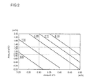
FIG. 2 is a chart showing relationship between amounts of C and Cr in a structural steel material, and a mechanical property of a shaft. -
FIG. 3(A) is a schematic diagram illustrating a joint portion of a turbine wheel and a shaft of a turbine after operation under a high temperature condition over a long period of time.FIG. 3(B) is a schematic diagram illustrating a joint portion of a turbine wheel and a shaft of a normal turbine. -
FIG. 4 is a chart showing relationship between amount of Cr and structure in temperature ranges in a case of a martensitic stainless steel containing 0.1 wt% of C. -
FIG. 5 is a schematic diagram illustrating a joint portion of a turbine wheel and a shaft of a normal turbine. -
FIG. 6 is a schematic diagram illustrating atomic state of a joint portion of a turbine wheel and a shaft of a turbine after operation under a high temperature condition over a long period of time. -
FIG. 7 is a schematic diagram illustrating a joint portion of a turbine wheel and a shaft after a damage of a turbine. - Embodiments of the present invention will now be described in detail with reference to the accompanying drawings. It is intended, however, that unless particularly specified, dimensions, materials, shapes, relative positions and the like of components described in the embodiments shall be interpreted as illustrative only and not limitative of the scope of the present invention.
-
Fig. 1 is a cross-sectional view illustrating a turbine for a compact turbocharger for an automobile according to a first embodiment of the present invention. - As illustrated in
Fig. 1 , a turbine component (hereinafter referred to as turbine body 1) used as a turbine for a compact turbocharger for an automobile comprises aturbine wheel 2 and ashaft 3. Theturbine wheel 2 has aconvex joint 2a, and the shaft has aconcave joint 3a. Theconvex joint 2a and theconcave joint 3a are fitted together, and theturbine wheel 2 and theshaft 3 are joined to each other with a Ni-basedbrazing filler metal 4. Theturbine wheel 2 and theshaft 3 are joined by adding the Ni-basedbrazing filler metal 4 between theturbine wheel 2 and theshaft 3 under a vacuum atmosphere. - The
turbine wheel 2 is composed of a TiAl-based alloy. The TiAl-based alloy contains Ti as the main constituent element and 28 to 35 wt% of Al, and it may further contain an additive element such as Nb, Cr, Mn, Si, W, C or B. In this embodiment, a TiAl-based alloy containing 31.3 wt% of Ti, 7.0 wt% of Al, 1.3 wt% of Nb and 0.03 wt% of C, and having been subjected to HIP treatment for a certain period of time at a temperature of at least 1,200°C after precision casting for the purpose of eliminating cast defect, was used. - The
shaft 3 is composed of a structural steel material. The structural steel material contains Fe as the main constituent element, 0.30 to 0.45 wt% of C, 0.85 to 1.25 wt% of Cr, 0.30 to 1.65 wt% of Mn, at most 0.030 wt% of C and at most 0.030 wt% of S. The structural steel material may further contain an additive element such as Ni or Mo, or N at a level of unavoidable impurities. An avoidable impurity means a substance contained in a slight amount in a structural steel material, because it is present in a raw material or it is unavoidably mixed in during production process. A level of unavoidable impurities means an amount in which an unavoidable impurity has little influence on properties of the structural steel material. - As the structural steel material, a manganese steel, a manganese-chrome steel, a chrome steel, a chrome-molybdenum steel, a nickel-chrome steel, a nickel-chrome-molybdenum steel, or the like may be used.
- In this embodiment, as the structural steel material, SCM435, which is a chrome-molybdenum steel containing 0.33 wt% of C and 0.90 wt% of Cr, was used.
- The reason why the range of the composition of the structural steel material is defined as above will be described hereinafter.
-
FIG. 2 is a chart showing relationship between amounts of C and Cr in a structural steel material, and a mechanical property of a shaft. - The numerical values in
Fig. 2 (i.e. 0.8, 1.0, 1.05, 1.1 and 1.15) each represents a spec ratio (hereinafter referred to as "spec value'') obtained by dividing the mechanical property (0.2% proof stress) of theshaft 3 after thermal treatment by the strength of theturbine wheel 2. - As shown in
Fig. 2 , as the amounts of C and Cr become larger, the strength of theshaft 3 becomes larger, that is, the spec value becomes larger. - Since the
turbine wheel 2 of e.g. a turbocharger is rotated at a high speed, a minimum strength required for resisting a centrifugal stress is defined as the spec value. In the present embodiment, the spec value at the minimum strength was set to be 1.0. In order to satisfy this spec value at the minimum strength, as shown by the line representing the spec value of 1.0 inFig. 2 , at least 0.30 wt% of C and at least 0.85 wt% of Cr are required to be contained. - On the other hand, it is generally known that the structural steel which is the material for the
shaft 3 has a better mechanical property after thermal treatment as the amounts of C and Cr are increased, but that as the strength becomes higher, the delayed cracking susceptibility after thermal treatment becomes higher. Since there is a risk of delayed crack if the strength is increased to at a strength level of a spec value of 1.15 inFig. 2 , the strength of theshaft 3 is preferably such that the speck value is at most 1.15. Therefore, based on the line representing the spec value of 1.15 inFig. 2 , the upper limits of the amount of C and Cr contained in theshaft 3 are set to be 0.45 wt% and 1.25 wt%, respectively. - A
shaft 3 having a high strength may be produced by quenching and annealing of the structural steel material having the above composition. -
FIG. 3(A) is a schematic diagram illustrating a joint portion of aturbine wheel 2 and ashaft 3 of aturbine body 1 after operation under a high temperature condition over a long period of time.FIG. 3(B) is a schematic diagram illustrating a joint portion of aturbine wheel 2 and a shaft-3 of anormal turbine body 1. - As illustrated in
Fig. 3(A) and Fig. 3(B) , theturbine wheel 2 and theshaft 3 are joined to each other with the Ni-based brazing filler material. As illustrated inFig. 3(A) , within theshaft 3 or the Ni- basedbrazing filler material 4 after operation of theturbine body 1 under a high temperature condition over a long period of time, voids, titanium carbide or a nitride is hardly formed, and it is confirmed that a normal state is maintained similarly to the case ofFig. 3(B) . - According to the joint part having the above composition, Cr contained in the
shaft 3 forms a bond with a part of C to generate chrome carbide or chrome nitride, whereby it is possible to suppress generation of voids, titanium carbide or chrome nitride in the vicinity of the boundary between theshaft 3 and the Ni-basedbrazing filler metal 4. In a conventional joint part, C and N in theshaft 3 are diffused toward theturbine wheel 2 due to diffusion phenomena, whereby voids formed by diffusion of C C, titanium carbide which is a carbide having a bond of C with C, or a nitride generated by diffusion of N, are formed a lot, and the brazing strength is significantly decreased. If a stress acts in the vicinity of the boundary between theturbine wheel 2 and theshaft 3 in such a state, cracks may arise and theshaft 3 may be damaged. On the other hand, in theshaft 3 according to the present invention, carbon will not be diffused toward theturbine wheel 2, and thus voids, titanium carbide or chrome nitride is hardly formed in the vicinity of the boundary between theshaft 3 and the Ni-based brazing filler metal. Further, as the amount of C contained in theshaft 3 is small, the amount of C to be diffused outside the shaft also becomes small. It is thereby possible to reduce voids formed in theshaft 3. - Furthermore, as the
shaft 3 contains Cr, it is possible to increase the strength of theshaft 3 in spite of the small amount of C. - Further, since the diffusion of C can be suppressed, the
turbine body 1 will not be damaged even after a long period of use under a high temperature of about 900°C to 1,000°C. - The
shaft 3 has chrome carbide; however, theshaft 3 has a steel structure homogenized and has the carbide spheroidized by thermal treatment. Thus, such a carbide will not be a weak point of strength as titanium carbide formed in a conventional steel member. - In this embodiment, a case where Cr is contained so as to be bonded with C. However, the element to be bonded with C is not limited to Cr, and it may, for example, be Nb ot V.
- A second embodiment of the present invention will be described hereinafter. In the following description, the same elements as those of the above embodiment are assigned with the same reference numerals as those of the above embodiment, and the same description thereof will be omitted, and difference from the above embodiment will be mainly described. The
shaft 3 of the turbine body according to the second embodiment is composed of a martensitic stainless steel material. - As described above, in the first embodiment, by employing a structural steel material as the
shaft 3, diffusion of C is suppressed, and decrease in the brazing strength is suppressed. Meanwhile, with improvement of fuel consumption of e.g. engines for automobiles in recent years, exhaust gas temperature has been increased up to about 1,000°C. When the exhaust gas temperature is increased, the Ni-basedbrazing filler metal 4 of theturbine body 1 may also be exposed to high temperature. Then, the brazing strength may be decreased after a long period operation even when the structural steel material is employed as theshaft 3. In such a case where theturbine body 1 is exposed to high temperature for a long period of time, a martensitic stainless steel material may be employed as theshaft 3. - The
turbine body 1 according to the second embodiment comprises aturbine wheel 2 and ashaft 3. Theturbine wheel 2 is composed of a TiAl-based alloy similarly to the case of the first embodiment. - The
shaft 3 is composed of a martensitic stainless steel material. The martensitic stainless steel material contains Fe as the main constituent element, at most 0.15 wt% of C, 11.5 to 13 wt% ofCr, at most 1.00 wt% of Si, at most 1.25 wt% of Mn and at most 0.060 wt% of P. The martensitic stainless steel material may further contain an additive element such as S, Ni, Mo or Pb, or N at a level of unavoidable impurities. - As the martensitic stainless steel material, a chrome stainless steel such as SUS403, SUS410, SUS410J1, SUS410F2, SUS416, SUS420J1, SUS420J2, SUS420F, SUS420F2, SUS431, SUS440A, SUS440B, SUS440C or SUS440F may, for example, be employed.
- In this embodiment, as the martensitic stainless steel material, SUS 403, which is a high-strength steel material containing 0.15 wt% of C and 13 wt% of Cr, was employed.
- The reason why the range of the composition of the martensitic steel material is defined as above will be described hereinafter.
- Regarding C, in general, a strength of a steel can be increased by containing more C. However, when C is contained in a large amount, as described above, many C may be diffused, whereby many voids and titanium carbide may be formed in the vicinity of the boundary between the
shaft 3 and the Ni-basedbrazing filler metal 4. Further, even if C is intended to be formed into chrome carbide in order to suppress the diffusion as the structural steel material described in the first embodiment, C may not be formed into chrome carbide in the steel material when the operating temperature of theturbine body 1 becomes about 1,000°C, and a small amount of carbon remaining in a solid solution state may be diffused toward theturbine wheel 2, whereby voids and titanium carbide may be formed. Thus, in a case where the exhaust gas temperature becomes about 1,000°C, it is required that the amount of C is smaller than the case of the structural steel material. In this embodiment, a large amount of Cr is contained to ensure the strength of theshaft 3, and at most 0.15 wt% of C is contained to suppress formation of voids or titanium carbide in the vicinity of the boundary between theshaft 3 and the Ni-basedbrazing filler metal 4. - Regarding Cr, in order to compensate for decrease in strength of the
shaft 3 due to the smaller amount of C, Cr is contained in an amount of at least 11.5 wt%.FIG. 4 is a chart showing relationship between the amount of Cr and the structure in several temperature ranges in a case of the martensitic stainless steel containing 0.1 wt% of C. The hatching area inFig. 4 represents the γ phase. As shown inFig. 4 , in a case where Cr is at most 13 wt%, when the steel in the region of the γ phase is cooled from the temperature of about 1,000C, transformation from the γ phase to the α phase occurs in the temperature range of from 800°C to 900°C. On the other hand, in a case where Cr is more than 13 wt%, as the steel is outside the γ phase, transformation from the γ phase to the α phase does not occur during thermal treatment, and the steel becomes a δ ferritic stainless steel, whereby it is not possible to increase the strength of theshaft 3. Therefore, the amount of Cr is set to be at most 13 wt%. As described above, in this embodiment, the amount of Cr is 11.5 to 13 wt%. - A
shaft 3 having a high strength may be produced by quenching the martensitic stainless steel having the above composition at a temperature of about 800°C to 1,200°C and then annealing it at a temperature of at most 800°C. - According to the joint part having the above composition, the amount of C contained in the
shaft 3 is small, and therefore it is possible to suppress diffusion of C as compared with a common stainless steel containing a large amount of C. Thus, voids or titanium carbide is hardly formed in the vicinity of the boundary between theshaft 3 and the Ni-basedbrazing filler metal 4. It is thereby possible to suppress cracks arising in the vicinity of the boundary between theshaft 3 and the Ni-basedbrazing filler metal 4. - Further, although the amount of C contained in the
shaft 3 is small, a large amount of Cr is contained, whereby it is possible to increase the strength of theshaft 3. - Further, a part of C contained in the
shaft 3 is bonded to Cr by thermal treatment to form chrome carbide. Since chrome carbide is excellent in structure stability even under a high temperature condition, even under a high temperature condition during operation of a turbocharger, chrome carbide will not be decomposed, and theshaft 3 will not be in a state such that C becomes solid solution therein. Thus, movement of C contained in the form of chrome carbide in theshaft 3 is limited, and diffusion of C from theshaft 3 towardturbine wheel 2 can be suppressed. Therefore, even after a long period of use under a high temperature of about 900°C to 1,000°C, theturbine body 1 will not be damaged.
Claims (5)
- A joint part comprising a steel member containing alloy elements including C and Cr, a TiAl-based alloy member, and a Ni-based. brazing filler metal via which the steel member and the TiAl-based alloy member are joined to each other,
wherein the steel member has a carbide and a nitride each forming a bond with at least one of the alloy elements at least on a side of a boundary with the Ni-based brazing filler metal, and diffusion of C and N to the Ni-based brazing filler metal adjacent to the TiAl-based alloy member is suppressed by the carbide and the nitride. - The joint part according to claim 1, wherein the steel member comprises a structural steel material containing 0.30 to 0.45 wt% of C and 0.85 to 1.25 wt% of Cr, and has a carbide and a nitride having a carbon and a nitrogen, respectively, bonded to at least one of the alloy elements including Cr at least on a side of a boundary with the Ni-based brazing filler metal in the structural steel material.
- The joint part according to claim 1, wherein the steel member comprises a martensitic stainless steel material containing at most 0.15 wt% of C and 11.5 to 13 wt% of Cr, and has a carbide and a nitride having a carbon and a nitrogen, respectively, bonded to at least one of the alloy elements including Cr by thermal treatment at least on a side of a boundary with the Ni-based brazing filler metal in the structural steel material.
- The joint part according to claim 2 or 3, wherein the nitrogen is mixed in during production (melting) of the steel member.
- The joint part according to any one of claims 1 to 4, wherein the TiAl-based alloy member is a turbine wheel of a turbine, and the steel member is a shaft of the turbine.
Applications Claiming Priority (2)
| Application Number | Priority Date | Filing Date | Title |
|---|---|---|---|
| JP2011264137 | 2011-12-01 | ||
| PCT/JP2012/079974 WO2013080828A1 (en) | 2011-12-01 | 2012-11-19 | Bonded component |
Publications (3)
| Publication Number | Publication Date |
|---|---|
| EP2786827A1 true EP2786827A1 (en) | 2014-10-08 |
| EP2786827A4 EP2786827A4 (en) | 2016-01-06 |
| EP2786827B1 EP2786827B1 (en) | 2020-01-01 |
Family
ID=48535290
Family Applications (1)
| Application Number | Title | Priority Date | Filing Date |
|---|---|---|---|
| EP12853153.0A Active EP2786827B1 (en) | 2011-12-01 | 2012-11-19 | Turbine body |
Country Status (5)
| Country | Link |
|---|---|
| US (1) | US10105778B2 (en) |
| EP (1) | EP2786827B1 (en) |
| JP (1) | JP5894189B2 (en) |
| CN (1) | CN103945972B (en) |
| WO (1) | WO2013080828A1 (en) |
Families Citing this family (4)
| Publication number | Priority date | Publication date | Assignee | Title |
|---|---|---|---|---|
| DE102013226594A1 (en) * | 2013-12-19 | 2015-06-25 | Robert Bosch Gmbh | Method for producing an impeller and a rotor |
| CN108699964B (en) | 2016-04-14 | 2020-11-17 | 株式会社Ihi | Turbine shaft and supercharger |
| US20190040762A1 (en) * | 2017-08-02 | 2019-02-07 | Cummins Inc. | Method and system for nozzle ring repair |
| CN111360351A (en) * | 2020-03-05 | 2020-07-03 | 西安陕鼓动力股份有限公司 | Process method for brazing Cr13 stainless steel impeller by Au-based brazing filler metal |
Family Cites Families (25)
| Publication number | Priority date | Publication date | Assignee | Title |
|---|---|---|---|---|
| JPH08311143A (en) | 1995-05-16 | 1996-11-26 | Nitto Denko Corp | Polycarbodiimide resin composition, method for producing heat-shrinkable molded product using the same, and heat-shrinkable molded product obtained thereby |
| JPH108924A (en) * | 1996-06-21 | 1998-01-13 | Daido Steel Co Ltd | Manufacturing method of valve for large diesel engine |
| ATE249571T1 (en) | 1996-10-18 | 2003-09-15 | Daido Steel Company Ltd | TI-AL TURBINE ROTOR AND METHOD FOR PRODUCING SUCH ROTOR |
| JPH10118764A (en) * | 1996-10-18 | 1998-05-12 | Daido Steel Co Ltd | Joining method of TiAl turbine impeller and rotor shaft |
| JPH10193087A (en) | 1996-12-27 | 1998-07-28 | Daido Steel Co Ltd | Method of manufacturing TiAl turbine rotor |
| JPH10124780A (en) | 1996-10-25 | 1998-05-15 | Nitsuko Corp | Emergency reporting device |
| JP3395576B2 (en) | 1997-06-11 | 2003-04-14 | 大和市 | Hydrogen sulfide generation prevention method |
| CN1068269C (en) | 1997-12-26 | 2001-07-11 | 冶金工业部钢铁研究总院 | Method for connecting Ti-Al alloy turbine rotor with structure steel shaft |
| JP4596577B2 (en) * | 1999-06-21 | 2010-12-08 | 本田技研工業株式会社 | Manufacturing method of billet for cold forging |
| JP4538878B2 (en) * | 2000-01-19 | 2010-09-08 | 大同特殊鋼株式会社 | Joining method between steel and titanium |
| JP2002252810A (en) | 2001-02-26 | 2002-09-06 | Aruze Corp | Signal switching device |
| JP2004090130A (en) | 2002-08-30 | 2004-03-25 | Mitsubishi Heavy Ind Ltd | JOINING METHOD FOR TiAL-BASE ALLOY AND STEEL PRODUCT |
| JP2005082844A (en) | 2003-09-08 | 2005-03-31 | Chiyoda Daiichi Kogyo Kk | Coating method for base material and coating structure |
| JP2006297474A (en) * | 2005-04-25 | 2006-11-02 | Daido Steel Co Ltd | Ti-Al alloy and steel joined body and joining method |
| CN1737525A (en) * | 2005-09-07 | 2006-02-22 | 哈尔滨工业大学 | Display method for metallurgical structure of solder joint interface of TiAl alloy/steel |
| CN100413636C (en) * | 2005-09-29 | 2008-08-27 | 哈尔滨工业大学 | High-strength connection method between TiAl-based alloy turbocharger and steel shaft |
| US20070199977A1 (en) * | 2006-02-28 | 2007-08-30 | Michael Pollard | Turbocharger turbine and shaft assembly |
| JP4304190B2 (en) | 2006-03-03 | 2009-07-29 | 精密工業株式会社 | Method of joining turbine wheel and rotor shaft |
| JP4666388B2 (en) | 2006-10-30 | 2011-04-06 | 株式会社神戸製鋼所 | Heat-resistant and wear-resistant high Cr cast iron |
| JP2008202544A (en) * | 2007-02-21 | 2008-09-04 | Mitsubishi Heavy Ind Ltd | Manufacturing method of rotor, and exhaust turbocharger having the rotor |
| JP2010005643A (en) * | 2008-06-25 | 2010-01-14 | Ihi Corp | Method for joining titanium member and steel member |
| CN101972877B (en) | 2010-11-03 | 2012-07-25 | 哈尔滨工业大学 | Contact reaction brazing connection method for TiAl based alloy and Ni based high-temperature alloy |
| CN102120281A (en) * | 2011-02-15 | 2011-07-13 | 洛阳双瑞精铸钛业有限公司 | Soldering method of rotor and steel shaft of titanium-aluminum turbocharger |
| CN102259217A (en) * | 2011-02-15 | 2011-11-30 | 洛阳双瑞精铸钛业有限公司 | Method for welding rotor and steel shaft of high-niobium titanium aluminum turbocharger |
| CN102211249A (en) * | 2011-05-26 | 2011-10-12 | 洛阳双瑞精铸钛业有限公司 | Method for connecting titanium-aluminum alloy turbine with 42CrMo steel shaft |
-
2012
- 2012-11-19 JP JP2013547101A patent/JP5894189B2/en active Active
- 2012-11-19 EP EP12853153.0A patent/EP2786827B1/en active Active
- 2012-11-19 CN CN201280057615.7A patent/CN103945972B/en active Active
- 2012-11-19 WO PCT/JP2012/079974 patent/WO2013080828A1/en not_active Ceased
- 2012-11-19 US US14/361,539 patent/US10105778B2/en active Active
Also Published As
| Publication number | Publication date |
|---|---|
| CN103945972A (en) | 2014-07-23 |
| US20140321905A1 (en) | 2014-10-30 |
| JPWO2013080828A1 (en) | 2015-04-27 |
| WO2013080828A1 (en) | 2013-06-06 |
| EP2786827B1 (en) | 2020-01-01 |
| EP2786827A4 (en) | 2016-01-06 |
| JP5894189B2 (en) | 2016-03-23 |
| CN103945972B (en) | 2016-08-17 |
| US10105778B2 (en) | 2018-10-23 |
Similar Documents
| Publication | Publication Date | Title |
|---|---|---|
| US11198930B2 (en) | Austenitic stainless steel plate | |
| EP2980254B1 (en) | Stainless steel alloy, turbocharger turbine housing formed from the stainless steel alloy | |
| JP6552385B2 (en) | Austenitic stainless steel plate with excellent heat resistance and workability, its manufacturing method, and exhaust parts made of stainless steel | |
| EP2765214B1 (en) | Stainless steel alloys, turbocharger turbine housings formed from the stainless steel alloys, and methods for manufacturing the same | |
| WO2009104792A1 (en) | Austenitic heat-resistant cast steel and exhaust system components made therefrom | |
| EP2980253B1 (en) | Stainless steel alloys and turbocharger turbine housings formed from the stainless steel alloys | |
| JP5605996B2 (en) | Austenitic stainless steel for heat-resistant materials | |
| US10105778B2 (en) | Joint part | |
| JP5717359B2 (en) | Heat-resistant austenitic stainless steel for metal gaskets | |
| EP3575430B1 (en) | Stainless steel alloys, turbocharger components formed from the stainless steel alloys, and methods for manufacturing the same | |
| JP5626338B2 (en) | Ferritic heat-resistant cast steel with excellent room temperature toughness and exhaust system parts made of it | |
| KR20220070349A (en) | High-temperature nickel-base alloy | |
| EP3196327B1 (en) | Stainless steel alloys, turbocharger turbine housings formed from the stainless steel alloys, and methods for manufacturing the same | |
| WO2014057875A1 (en) | Ferritic heat-resistant cast steel with excellent machinability and exhaust component consisting of same | |
| US10316694B2 (en) | Stainless steel alloys, turbocharger turbine housings formed from the stainless steel alloys, and methods for manufacturing the same | |
| US10240223B2 (en) | Ni-based alloy having excellent high-temperature creep characteristics, and gas turbine member using the same | |
| JP2012177370A (en) | Steam turbine rotor | |
| JP7743971B2 (en) | iron castings | |
| EP2910661B1 (en) | Stainless steel alloys, turbocharger turbine housings formed from the stainless steel alloys, and methods for manufacturing the same | |
| WO2016142963A1 (en) | Austenitic heat-resistant steel and turbine component |
Legal Events
| Date | Code | Title | Description |
|---|---|---|---|
| PUAI | Public reference made under article 153(3) epc to a published international application that has entered the european phase |
Free format text: ORIGINAL CODE: 0009012 |
|
| 17P | Request for examination filed |
Effective date: 20140530 |
|
| AK | Designated contracting states |
Kind code of ref document: A1 Designated state(s): AL AT BE BG CH CY CZ DE DK EE ES FI FR GB GR HR HU IE IS IT LI LT LU LV MC MK MT NL NO PL PT RO RS SE SI SK SM TR |
|
| DAX | Request for extension of the european patent (deleted) | ||
| RA4 | Supplementary search report drawn up and despatched (corrected) |
Effective date: 20151204 |
|
| RIC1 | Information provided on ipc code assigned before grant |
Ipc: F01D 5/02 20060101ALI20151130BHEP Ipc: F01D 5/04 20060101ALI20151130BHEP Ipc: B23K 35/30 20060101ALI20151130BHEP Ipc: B23K 101/00 20060101ALI20151130BHEP Ipc: F01D 25/00 20060101ALI20151130BHEP Ipc: C22C 38/40 20060101ALI20151130BHEP Ipc: C22C 38/18 20060101ALI20151130BHEP Ipc: C22C 14/00 20060101ALI20151130BHEP Ipc: C22C 38/00 20060101ALI20151130BHEP Ipc: B23K 103/24 20060101ALI20151130BHEP Ipc: F02B 39/00 20060101ALI20151130BHEP Ipc: C22C 38/38 20060101ALI20151130BHEP Ipc: C22C 38/22 20060101ALI20151130BHEP Ipc: F02C 7/00 20060101ALI20151130BHEP Ipc: B23K 35/00 20060101ALI20151130BHEP Ipc: F01D 5/28 20060101ALI20151130BHEP Ipc: B23K 1/19 20060101AFI20151130BHEP Ipc: B23K 35/02 20060101ALI20151130BHEP Ipc: B32B 15/01 20060101ALI20151130BHEP Ipc: F01D 5/06 20060101ALI20151130BHEP Ipc: B23K 1/00 20060101ALI20151130BHEP |
|
| STAA | Information on the status of an ep patent application or granted ep patent |
Free format text: STATUS: REQUEST FOR EXAMINATION WAS MADE |
|
| R17P | Request for examination filed (corrected) |
Effective date: 20140530 |
|
| STAA | Information on the status of an ep patent application or granted ep patent |
Free format text: STATUS: EXAMINATION IS IN PROGRESS |
|
| 17Q | First examination report despatched |
Effective date: 20170601 |
|
| RAP1 | Party data changed (applicant data changed or rights of an application transferred) |
Owner name: MITSUBISHI HEAVY INDUSTRIES ENGINE & TURBOCHARGER, |
|
| GRAP | Despatch of communication of intention to grant a patent |
Free format text: ORIGINAL CODE: EPIDOSNIGR1 |
|
| STAA | Information on the status of an ep patent application or granted ep patent |
Free format text: STATUS: GRANT OF PATENT IS INTENDED |
|
| INTG | Intention to grant announced |
Effective date: 20190731 |
|
| GRAS | Grant fee paid |
Free format text: ORIGINAL CODE: EPIDOSNIGR3 |
|
| GRAA | (expected) grant |
Free format text: ORIGINAL CODE: 0009210 |
|
| STAA | Information on the status of an ep patent application or granted ep patent |
Free format text: STATUS: THE PATENT HAS BEEN GRANTED |
|
| AK | Designated contracting states |
Kind code of ref document: B1 Designated state(s): AL AT BE BG CH CY CZ DE DK EE ES FI FR GB GR HR HU IE IS IT LI LT LU LV MC MK MT NL NO PL PT RO RS SE SI SK SM TR |
|
| REG | Reference to a national code |
Ref country code: GB Ref legal event code: FG4D |
|
| REG | Reference to a national code |
Ref country code: CH Ref legal event code: EP Ref country code: AT Ref legal event code: REF Ref document number: 1219163 Country of ref document: AT Kind code of ref document: T Effective date: 20200115 |
|
| REG | Reference to a national code |
Ref country code: IE Ref legal event code: FG4D |
|
| REG | Reference to a national code |
Ref country code: DE Ref legal event code: R096 Ref document number: 602012066993 Country of ref document: DE |
|
| REG | Reference to a national code |
Ref country code: NL Ref legal event code: FP |
|
| REG | Reference to a national code |
Ref country code: LT Ref legal event code: MG4D |
|
| PG25 | Lapsed in a contracting state [announced via postgrant information from national office to epo] |
Ref country code: CZ Free format text: LAPSE BECAUSE OF FAILURE TO SUBMIT A TRANSLATION OF THE DESCRIPTION OR TO PAY THE FEE WITHIN THE PRESCRIBED TIME-LIMIT Effective date: 20200101 Ref country code: PT Free format text: LAPSE BECAUSE OF FAILURE TO SUBMIT A TRANSLATION OF THE DESCRIPTION OR TO PAY THE FEE WITHIN THE PRESCRIBED TIME-LIMIT Effective date: 20200527 Ref country code: LT Free format text: LAPSE BECAUSE OF FAILURE TO SUBMIT A TRANSLATION OF THE DESCRIPTION OR TO PAY THE FEE WITHIN THE PRESCRIBED TIME-LIMIT Effective date: 20200101 Ref country code: RS Free format text: LAPSE BECAUSE OF FAILURE TO SUBMIT A TRANSLATION OF THE DESCRIPTION OR TO PAY THE FEE WITHIN THE PRESCRIBED TIME-LIMIT Effective date: 20200101 Ref country code: FI Free format text: LAPSE BECAUSE OF FAILURE TO SUBMIT A TRANSLATION OF THE DESCRIPTION OR TO PAY THE FEE WITHIN THE PRESCRIBED TIME-LIMIT Effective date: 20200101 Ref country code: NO Free format text: LAPSE BECAUSE OF FAILURE TO SUBMIT A TRANSLATION OF THE DESCRIPTION OR TO PAY THE FEE WITHIN THE PRESCRIBED TIME-LIMIT Effective date: 20200401 |
|
| PG25 | Lapsed in a contracting state [announced via postgrant information from national office to epo] |
Ref country code: BG Free format text: LAPSE BECAUSE OF FAILURE TO SUBMIT A TRANSLATION OF THE DESCRIPTION OR TO PAY THE FEE WITHIN THE PRESCRIBED TIME-LIMIT Effective date: 20200401 Ref country code: HR Free format text: LAPSE BECAUSE OF FAILURE TO SUBMIT A TRANSLATION OF THE DESCRIPTION OR TO PAY THE FEE WITHIN THE PRESCRIBED TIME-LIMIT Effective date: 20200101 Ref country code: GR Free format text: LAPSE BECAUSE OF FAILURE TO SUBMIT A TRANSLATION OF THE DESCRIPTION OR TO PAY THE FEE WITHIN THE PRESCRIBED TIME-LIMIT Effective date: 20200402 Ref country code: SE Free format text: LAPSE BECAUSE OF FAILURE TO SUBMIT A TRANSLATION OF THE DESCRIPTION OR TO PAY THE FEE WITHIN THE PRESCRIBED TIME-LIMIT Effective date: 20200101 Ref country code: IS Free format text: LAPSE BECAUSE OF FAILURE TO SUBMIT A TRANSLATION OF THE DESCRIPTION OR TO PAY THE FEE WITHIN THE PRESCRIBED TIME-LIMIT Effective date: 20200501 Ref country code: LV Free format text: LAPSE BECAUSE OF FAILURE TO SUBMIT A TRANSLATION OF THE DESCRIPTION OR TO PAY THE FEE WITHIN THE PRESCRIBED TIME-LIMIT Effective date: 20200101 |
|
| REG | Reference to a national code |
Ref country code: DE Ref legal event code: R097 Ref document number: 602012066993 Country of ref document: DE |
|
| PG25 | Lapsed in a contracting state [announced via postgrant information from national office to epo] |
Ref country code: SM Free format text: LAPSE BECAUSE OF FAILURE TO SUBMIT A TRANSLATION OF THE DESCRIPTION OR TO PAY THE FEE WITHIN THE PRESCRIBED TIME-LIMIT Effective date: 20200101 Ref country code: EE Free format text: LAPSE BECAUSE OF FAILURE TO SUBMIT A TRANSLATION OF THE DESCRIPTION OR TO PAY THE FEE WITHIN THE PRESCRIBED TIME-LIMIT Effective date: 20200101 Ref country code: DK Free format text: LAPSE BECAUSE OF FAILURE TO SUBMIT A TRANSLATION OF THE DESCRIPTION OR TO PAY THE FEE WITHIN THE PRESCRIBED TIME-LIMIT Effective date: 20200101 Ref country code: RO Free format text: LAPSE BECAUSE OF FAILURE TO SUBMIT A TRANSLATION OF THE DESCRIPTION OR TO PAY THE FEE WITHIN THE PRESCRIBED TIME-LIMIT Effective date: 20200101 Ref country code: SK Free format text: LAPSE BECAUSE OF FAILURE TO SUBMIT A TRANSLATION OF THE DESCRIPTION OR TO PAY THE FEE WITHIN THE PRESCRIBED TIME-LIMIT Effective date: 20200101 Ref country code: ES Free format text: LAPSE BECAUSE OF FAILURE TO SUBMIT A TRANSLATION OF THE DESCRIPTION OR TO PAY THE FEE WITHIN THE PRESCRIBED TIME-LIMIT Effective date: 20200101 |
|
| PLBE | No opposition filed within time limit |
Free format text: ORIGINAL CODE: 0009261 |
|
| STAA | Information on the status of an ep patent application or granted ep patent |
Free format text: STATUS: NO OPPOSITION FILED WITHIN TIME LIMIT |
|
| REG | Reference to a national code |
Ref country code: AT Ref legal event code: MK05 Ref document number: 1219163 Country of ref document: AT Kind code of ref document: T Effective date: 20200101 |
|
| 26N | No opposition filed |
Effective date: 20201002 |
|
| PGFP | Annual fee paid to national office [announced via postgrant information from national office to epo] |
Ref country code: NL Payment date: 20201015 Year of fee payment: 9 |
|
| PG25 | Lapsed in a contracting state [announced via postgrant information from national office to epo] |
Ref country code: IT Free format text: LAPSE BECAUSE OF FAILURE TO SUBMIT A TRANSLATION OF THE DESCRIPTION OR TO PAY THE FEE WITHIN THE PRESCRIBED TIME-LIMIT Effective date: 20200101 Ref country code: AT Free format text: LAPSE BECAUSE OF FAILURE TO SUBMIT A TRANSLATION OF THE DESCRIPTION OR TO PAY THE FEE WITHIN THE PRESCRIBED TIME-LIMIT Effective date: 20200101 |
|
| PGFP | Annual fee paid to national office [announced via postgrant information from national office to epo] |
Ref country code: GB Payment date: 20201112 Year of fee payment: 9 Ref country code: FR Payment date: 20201013 Year of fee payment: 9 |
|
| PG25 | Lapsed in a contracting state [announced via postgrant information from national office to epo] |
Ref country code: SI Free format text: LAPSE BECAUSE OF FAILURE TO SUBMIT A TRANSLATION OF THE DESCRIPTION OR TO PAY THE FEE WITHIN THE PRESCRIBED TIME-LIMIT Effective date: 20200101 Ref country code: PL Free format text: LAPSE BECAUSE OF FAILURE TO SUBMIT A TRANSLATION OF THE DESCRIPTION OR TO PAY THE FEE WITHIN THE PRESCRIBED TIME-LIMIT Effective date: 20200101 |
|
| PG25 | Lapsed in a contracting state [announced via postgrant information from national office to epo] |
Ref country code: MC Free format text: LAPSE BECAUSE OF FAILURE TO SUBMIT A TRANSLATION OF THE DESCRIPTION OR TO PAY THE FEE WITHIN THE PRESCRIBED TIME-LIMIT Effective date: 20200101 |
|
| REG | Reference to a national code |
Ref country code: CH Ref legal event code: PL |
|
| PG25 | Lapsed in a contracting state [announced via postgrant information from national office to epo] |
Ref country code: LU Free format text: LAPSE BECAUSE OF NON-PAYMENT OF DUE FEES Effective date: 20201119 |
|
| REG | Reference to a national code |
Ref country code: BE Ref legal event code: MM Effective date: 20201130 |
|
| PG25 | Lapsed in a contracting state [announced via postgrant information from national office to epo] |
Ref country code: CH Free format text: LAPSE BECAUSE OF NON-PAYMENT OF DUE FEES Effective date: 20201130 Ref country code: LI Free format text: LAPSE BECAUSE OF NON-PAYMENT OF DUE FEES Effective date: 20201130 |
|
| PG25 | Lapsed in a contracting state [announced via postgrant information from national office to epo] |
Ref country code: IE Free format text: LAPSE BECAUSE OF NON-PAYMENT OF DUE FEES Effective date: 20201119 |
|
| PG25 | Lapsed in a contracting state [announced via postgrant information from national office to epo] |
Ref country code: TR Free format text: LAPSE BECAUSE OF FAILURE TO SUBMIT A TRANSLATION OF THE DESCRIPTION OR TO PAY THE FEE WITHIN THE PRESCRIBED TIME-LIMIT Effective date: 20200101 Ref country code: MT Free format text: LAPSE BECAUSE OF FAILURE TO SUBMIT A TRANSLATION OF THE DESCRIPTION OR TO PAY THE FEE WITHIN THE PRESCRIBED TIME-LIMIT Effective date: 20200101 Ref country code: CY Free format text: LAPSE BECAUSE OF FAILURE TO SUBMIT A TRANSLATION OF THE DESCRIPTION OR TO PAY THE FEE WITHIN THE PRESCRIBED TIME-LIMIT Effective date: 20200101 |
|
| PG25 | Lapsed in a contracting state [announced via postgrant information from national office to epo] |
Ref country code: MK Free format text: LAPSE BECAUSE OF FAILURE TO SUBMIT A TRANSLATION OF THE DESCRIPTION OR TO PAY THE FEE WITHIN THE PRESCRIBED TIME-LIMIT Effective date: 20200101 Ref country code: AL Free format text: LAPSE BECAUSE OF FAILURE TO SUBMIT A TRANSLATION OF THE DESCRIPTION OR TO PAY THE FEE WITHIN THE PRESCRIBED TIME-LIMIT Effective date: 20200101 |
|
| REG | Reference to a national code |
Ref country code: NL Ref legal event code: MM Effective date: 20211201 |
|
| GBPC | Gb: european patent ceased through non-payment of renewal fee |
Effective date: 20211119 |
|
| PG25 | Lapsed in a contracting state [announced via postgrant information from national office to epo] |
Ref country code: BE Free format text: LAPSE BECAUSE OF NON-PAYMENT OF DUE FEES Effective date: 20201130 |
|
| PG25 | Lapsed in a contracting state [announced via postgrant information from national office to epo] |
Ref country code: NL Free format text: LAPSE BECAUSE OF NON-PAYMENT OF DUE FEES Effective date: 20211201 |
|
| PG25 | Lapsed in a contracting state [announced via postgrant information from national office to epo] |
Ref country code: GB Free format text: LAPSE BECAUSE OF NON-PAYMENT OF DUE FEES Effective date: 20211119 |
|
| PG25 | Lapsed in a contracting state [announced via postgrant information from national office to epo] |
Ref country code: FR Free format text: LAPSE BECAUSE OF NON-PAYMENT OF DUE FEES Effective date: 20211130 |
|
| PGFP | Annual fee paid to national office [announced via postgrant information from national office to epo] |
Ref country code: DE Payment date: 20250930 Year of fee payment: 14 |