EP2785239B1 - Tear duct resistance measuring system - Google Patents
Tear duct resistance measuring system Download PDFInfo
- Publication number
- EP2785239B1 EP2785239B1 EP12813416.0A EP12813416A EP2785239B1 EP 2785239 B1 EP2785239 B1 EP 2785239B1 EP 12813416 A EP12813416 A EP 12813416A EP 2785239 B1 EP2785239 B1 EP 2785239B1
- Authority
- EP
- European Patent Office
- Prior art keywords
- flow
- cannula
- punctum
- tubular element
- pressure
- Prior art date
- Legal status (The legal status is an assumption and is not a legal conclusion. Google has not performed a legal analysis and makes no representation as to the accuracy of the status listed.)
- Active
Links
Images
Classifications
-
- A—HUMAN NECESSITIES
- A61—MEDICAL OR VETERINARY SCIENCE; HYGIENE
- A61B—DIAGNOSIS; SURGERY; IDENTIFICATION
- A61B3/00—Apparatus for testing the eyes; Instruments for examining the eyes
- A61B3/10—Objective types, i.e. instruments for examining the eyes independent of the patients' perceptions or reactions
- A61B3/101—Objective types, i.e. instruments for examining the eyes independent of the patients' perceptions or reactions for examining the tear film
-
- A—HUMAN NECESSITIES
- A61—MEDICAL OR VETERINARY SCIENCE; HYGIENE
- A61B—DIAGNOSIS; SURGERY; IDENTIFICATION
- A61B3/00—Apparatus for testing the eyes; Instruments for examining the eyes
- A61B3/0008—Apparatus for testing the eyes; Instruments for examining the eyes provided with illuminating means
-
- A—HUMAN NECESSITIES
- A61—MEDICAL OR VETERINARY SCIENCE; HYGIENE
- A61B—DIAGNOSIS; SURGERY; IDENTIFICATION
- A61B3/00—Apparatus for testing the eyes; Instruments for examining the eyes
- A61B3/10—Objective types, i.e. instruments for examining the eyes independent of the patients' perceptions or reactions
-
- A—HUMAN NECESSITIES
- A61—MEDICAL OR VETERINARY SCIENCE; HYGIENE
- A61B—DIAGNOSIS; SURGERY; IDENTIFICATION
- A61B5/00—Measuring for diagnostic purposes; Identification of persons
- A61B5/68—Arrangements of detecting, measuring or recording means, e.g. sensors, in relation to patient
- A61B5/6801—Arrangements of detecting, measuring or recording means, e.g. sensors, in relation to patient specially adapted to be attached to or worn on the body surface
- A61B5/6813—Specially adapted to be attached to a specific body part
- A61B5/6814—Head
- A61B5/6821—Eye
-
- A—HUMAN NECESSITIES
- A61—MEDICAL OR VETERINARY SCIENCE; HYGIENE
- A61F—FILTERS IMPLANTABLE INTO BLOOD VESSELS; PROSTHESES; DEVICES PROVIDING PATENCY TO, OR PREVENTING COLLAPSING OF, TUBULAR STRUCTURES OF THE BODY, e.g. STENTS; ORTHOPAEDIC, NURSING OR CONTRACEPTIVE DEVICES; FOMENTATION; TREATMENT OR PROTECTION OF EYES OR EARS; BANDAGES, DRESSINGS OR ABSORBENT PADS; FIRST-AID KITS
- A61F9/00—Methods or devices for treatment of the eyes; Devices for putting in contact-lenses; Devices to correct squinting; Apparatus to guide the blind; Protective devices for the eyes, carried on the body or in the hand
- A61F9/0008—Introducing ophthalmic products into the ocular cavity or retaining products therein
- A61F9/0017—Introducing ophthalmic products into the ocular cavity or retaining products therein implantable in, or in contact with, the eye, e.g. ocular inserts
-
- A—HUMAN NECESSITIES
- A61—MEDICAL OR VETERINARY SCIENCE; HYGIENE
- A61F—FILTERS IMPLANTABLE INTO BLOOD VESSELS; PROSTHESES; DEVICES PROVIDING PATENCY TO, OR PREVENTING COLLAPSING OF, TUBULAR STRUCTURES OF THE BODY, e.g. STENTS; ORTHOPAEDIC, NURSING OR CONTRACEPTIVE DEVICES; FOMENTATION; TREATMENT OR PROTECTION OF EYES OR EARS; BANDAGES, DRESSINGS OR ABSORBENT PADS; FIRST-AID KITS
- A61F9/00—Methods or devices for treatment of the eyes; Devices for putting in contact-lenses; Devices to correct squinting; Apparatus to guide the blind; Protective devices for the eyes, carried on the body or in the hand
- A61F9/007—Methods or devices for eye surgery
- A61F9/00736—Instruments for removal of intra-ocular material or intra-ocular injection, e.g. cataract instruments
-
- A—HUMAN NECESSITIES
- A61—MEDICAL OR VETERINARY SCIENCE; HYGIENE
- A61F—FILTERS IMPLANTABLE INTO BLOOD VESSELS; PROSTHESES; DEVICES PROVIDING PATENCY TO, OR PREVENTING COLLAPSING OF, TUBULAR STRUCTURES OF THE BODY, e.g. STENTS; ORTHOPAEDIC, NURSING OR CONTRACEPTIVE DEVICES; FOMENTATION; TREATMENT OR PROTECTION OF EYES OR EARS; BANDAGES, DRESSINGS OR ABSORBENT PADS; FIRST-AID KITS
- A61F9/00—Methods or devices for treatment of the eyes; Devices for putting in contact-lenses; Devices to correct squinting; Apparatus to guide the blind; Protective devices for the eyes, carried on the body or in the hand
- A61F9/007—Methods or devices for eye surgery
- A61F9/00772—Apparatus for restoration of tear ducts
-
- A—HUMAN NECESSITIES
- A61—MEDICAL OR VETERINARY SCIENCE; HYGIENE
- A61M—DEVICES FOR INTRODUCING MEDIA INTO, OR ONTO, THE BODY; DEVICES FOR TRANSDUCING BODY MEDIA OR FOR TAKING MEDIA FROM THE BODY; DEVICES FOR PRODUCING OR ENDING SLEEP OR STUPOR
- A61M39/00—Tubes, tube connectors, tube couplings, valves, access sites or the like, specially adapted for medical use
- A61M39/22—Valves or arrangement of valves
- A61M39/24—Check- or non-return valves
-
- A—HUMAN NECESSITIES
- A61—MEDICAL OR VETERINARY SCIENCE; HYGIENE
- A61M—DEVICES FOR INTRODUCING MEDIA INTO, OR ONTO, THE BODY; DEVICES FOR TRANSDUCING BODY MEDIA OR FOR TAKING MEDIA FROM THE BODY; DEVICES FOR PRODUCING OR ENDING SLEEP OR STUPOR
- A61M5/00—Devices for bringing media into the body in a subcutaneous, intra-vascular or intramuscular way; Accessories therefor, e.g. filling or cleaning devices, arm-rests
- A61M5/178—Syringes
-
- A—HUMAN NECESSITIES
- A61—MEDICAL OR VETERINARY SCIENCE; HYGIENE
- A61B—DIAGNOSIS; SURGERY; IDENTIFICATION
- A61B10/00—Instruments for taking body samples for diagnostic purposes; Other methods or instruments for diagnosis, e.g. for vaccination diagnosis, sex determination or ovulation-period determination; Throat striking implements
- A61B10/0045—Devices for taking samples of body liquids
- A61B2010/0067—Tear or lachrymal fluid
-
- A—HUMAN NECESSITIES
- A61—MEDICAL OR VETERINARY SCIENCE; HYGIENE
- A61B—DIAGNOSIS; SURGERY; IDENTIFICATION
- A61B5/00—Measuring for diagnostic purposes; Identification of persons
- A61B5/03—Measuring fluid pressure within the body other than blood pressure, e.g. cerebral pressure ; Measuring pressure in body tissues or organs
- A61B5/036—Measuring fluid pressure within the body other than blood pressure, e.g. cerebral pressure ; Measuring pressure in body tissues or organs by means introduced into body tracts
-
- A—HUMAN NECESSITIES
- A61—MEDICAL OR VETERINARY SCIENCE; HYGIENE
- A61M—DEVICES FOR INTRODUCING MEDIA INTO, OR ONTO, THE BODY; DEVICES FOR TRANSDUCING BODY MEDIA OR FOR TAKING MEDIA FROM THE BODY; DEVICES FOR PRODUCING OR ENDING SLEEP OR STUPOR
- A61M5/00—Devices for bringing media into the body in a subcutaneous, intra-vascular or intramuscular way; Accessories therefor, e.g. filling or cleaning devices, arm-rests
- A61M5/14—Infusion devices, e.g. infusing by gravity; Blood infusion; Accessories therefor
- A61M5/168—Means for controlling media flow to the body or for metering media to the body, e.g. drip meters, counters ; Monitoring media flow to the body
- A61M5/172—Means for controlling media flow to the body or for metering media to the body, e.g. drip meters, counters ; Monitoring media flow to the body electrical or electronic
- A61M5/1723—Means for controlling media flow to the body or for metering media to the body, e.g. drip meters, counters ; Monitoring media flow to the body electrical or electronic using feedback of body parameters, e.g. blood-sugar, pressure
- A61M2005/1726—Means for controlling media flow to the body or for metering media to the body, e.g. drip meters, counters ; Monitoring media flow to the body electrical or electronic using feedback of body parameters, e.g. blood-sugar, pressure the body parameters being measured at, or proximate to, the infusion site
-
- A—HUMAN NECESSITIES
- A61—MEDICAL OR VETERINARY SCIENCE; HYGIENE
- A61M—DEVICES FOR INTRODUCING MEDIA INTO, OR ONTO, THE BODY; DEVICES FOR TRANSDUCING BODY MEDIA OR FOR TAKING MEDIA FROM THE BODY; DEVICES FOR PRODUCING OR ENDING SLEEP OR STUPOR
- A61M2205/00—General characteristics of the apparatus
- A61M2205/33—Controlling, regulating or measuring
- A61M2205/3331—Pressure; Flow
- A61M2205/3344—Measuring or controlling pressure at the body treatment site
-
- A—HUMAN NECESSITIES
- A61—MEDICAL OR VETERINARY SCIENCE; HYGIENE
- A61M—DEVICES FOR INTRODUCING MEDIA INTO, OR ONTO, THE BODY; DEVICES FOR TRANSDUCING BODY MEDIA OR FOR TAKING MEDIA FROM THE BODY; DEVICES FOR PRODUCING OR ENDING SLEEP OR STUPOR
- A61M2205/00—General characteristics of the apparatus
- A61M2205/58—Means for facilitating use, e.g. by people with impaired vision
- A61M2205/587—Lighting arrangements
-
- A—HUMAN NECESSITIES
- A61—MEDICAL OR VETERINARY SCIENCE; HYGIENE
- A61M—DEVICES FOR INTRODUCING MEDIA INTO, OR ONTO, THE BODY; DEVICES FOR TRANSDUCING BODY MEDIA OR FOR TAKING MEDIA FROM THE BODY; DEVICES FOR PRODUCING OR ENDING SLEEP OR STUPOR
- A61M2210/00—Anatomical parts of the body
- A61M2210/06—Head
- A61M2210/0612—Eyes
Definitions
- the present invention relates to a system and to a method for measuring the flow properties of a tear duct, to ascertain the flow resistance of the tear duct.
- the tear drainage system collects the tears from the inner corner of the eye through a small opening (punctum) in the margin of the eyelid, there being one punctum in each of the upper and lower eyelids.
- Punctum leads to a canaliculus which passes horizontally through the medial end of the eyelid towards the nose, the canaliculi usually joining to form a single common canaliculus as they reach the lacrimal sac.
- the tear duct changes to an inferior direction passing downward to become the lacrimal duct and finally exiting into the lower part of the nose.
- Narrowing or occlusion of the tear duct can occur at any point in its course from the eye to nose.
- the evolution of tear duct obstruction involves a progressive narrowing of the tear duct from an initially fully open state, through in some cases to complete occlusion.
- the consequent reduction in tear drainage leads to troublesome watering from the eye, soreness of the eyelids, and sometimes infections.
- the mainstay of clinical examination is to use a lacrimal cannula inserted into the punctum and connected to a syringe to irrigate fluid down the tear system.
- the syringe and cannula are hand-held, fluid is irrigated under pressure and the passage of fluid to the nose or regurgitation back from the same or, because they are connected, the opposite punctum, is identified.
- a subjective estimate can be made of the level of resistance to fluid flow.
- the present invention provides a system for measuring the flow properties of a patient's tear duct to ascertain the flow resistance of the tear duct, the system comprising: a means to generate a flow of liquid, communicating with a cannula to supply liquid into a punctum of the patient's eye to irrigate the tear duct so the liquid flows through the tear duct from the punctum to the nasal passage, the cannula defining a tip and being able to seal to the punctum; a motor to actuate the flow-generating means; a pressure sensor to monitor the pressure of the liquid supplied to the punctum; a monitoring circuit to which signals from the pressure sensor are provided, arranged to provide an indication of the flow resistance from those signals; and a feedback circuit to control the motor in accordance with signals from the pressure sensor, either to maintain a preset liquid pressure, or to ensure that the liquid pressure does not exceed a preset threshold; wherein the flow-generating means communicates with the cannula through one or more components that define a flow path, the flow path being defined
- the system may be portable, or may be mounted on a microscope, or indeed may be usable in either way.
- the system may be battery-powered.
- the system also includes means to close the other punctum of the eye, for example a clip or a plug.
- the closure means ensure that the liquid introduced into the punctum must flow through the tear duct. Without such a closure means, leakage of injected liquid might otherwise occur through the other punctum, giving misleadingly low values for fluid pressure. If the tear duct is completely obstructed there can be no through flow, and the feedback circuit ensures the liquid pressure does not exceed the preset threshold. This ensures the patient is not subjected to pain or damage to the tear duct, as could otherwise occur.
- the system provides feedback control of the irrigation and ensures that the lacrimal system is closed apart from the nasal exit point of the tear duct. Further features ensure that the system is practical for clinical use.
- the flow-generating means is a syringe.
- the motor is arranged to actuate the syringe.
- the flow rate has a predetermined value, for example as determined by the voltage applied to a motor.
- the monitored pressure is indicative of the flow resistance of the tear duct, and may be used as a parameter representing the flow resistance.
- the system may also comprise means to monitor the flow rate of the liquid supplied to the punctum. Signals from the flow rate monitor may then be supplied to the monitoring circuit.
- the system is capable of irrigating the tear duct, while monitoring both the pressure applied and the flow rate through the lacrimal system.
- the system uses a syringe driver so that the rate of flow of the liquid is controlled electronically in response to continuous pressure recordings from a pressure transducer in the fluid delivery system to the tear duct.
- a certain motor speed on the syringe driver will propel the plunger of the syringe at a known linear rate from which the rate of delivery of fluid from any particular size or type of syringe can be ascertained.
- the flow rate may therefore be monitored by monitoring the movement of the syringe plunger, or by monitoring the motor which drives the syringe plunger.
- the liquid flow may be directly monitored. (As mentioned above, in some cases the liquid flow rate need not be monitored.)
- the syringe communicates with the cannula either directly, or through one or more components that define a flow path, for example through a flexible tube.
- the pressure sensor may be within the syringe, or within another part of the flow path, in order to monitor the pressure of the liquid supplied to the punctum.
- the short tubular element may be less than 100 mm long, but preferably at least 5 mm long, and more preferably at least 20 mm long; it therefore provides a convenient way for the operator to manipulate the cannula, for example with his fingertips.
- the cannula may be readily detachable from the short tubular element, so it can be replaced by a cannula of a different shape or size. Alternatively the cannula may be integral with the short tubular element.
- the short tubular element may include means to activate the system, such as a touch-sensitive switch.
- the pressure sensor is within the short tubular element, which may be referred to as a transducer module.
- Measurements are preferably only made when the pressure and flow rate are stable, if only for a few seconds, as measurements made in a non-steady-state condition may give inaccurate results. With two variables it would be possible to keep either one constant and measure the other. Thus if there is a constant rate of flow the pressure could be recorded, and the system is arranged to reduce or cut off the flow if the pressure becomes excessive.
- a preferred alternative is to specify the preset pressure at which the system will irrigate the tear duct and to vary the speed of the syringe driver, and so the flow rate, to provide this.
- a substantial advantage of the system arises where it is portable, so it can be used hand-held, but where it can also be mounted on the slit-lamp biomicroscope used for eye examination. Irrigating the tear ducts with the patient seated at the microscope is currently very difficult in view of the limited space available to work in. A further problem is the necessarily long length of a filled syringe attached to a currently-available lacrimal irrigating cannula. Such length makes positioning the tip of the cannula in the punctum and applying pressure to the syringe very awkward and there is potential for damage to the tear duct, eyelid or eye. Typically, syringing of the tear duct therefore takes place away from the microscope, often requiring transfer to a couch.
- the system of the invention allows for testing at the microscope by incorporating a number of features.
- the syringe driver is portable and of a compact size. It is designed to fit within the limited available space on the microscope, and to be removably mounted on the base plate of the microscope used for other ophthalmic work.
- a length of flexible tubing connects the tip of the syringe to the short tubular element, to which is attached a short cannula.
- the combination of the short tubular element and the cannula is sufficiently compact to allow ready manipulation in the narrow confines of the microscope and simple placement of the cannula. Achieving this however requires the use of both of the operator's hands, one to hold the eyelid stable, the other to hold the cannula, to insert it and hold it within the punctum to generate a seal.
- the system therefore includes the switch in the vicinity of the cannula for convenient use by the operator; such a switch may be provided in the short tubular element and designed to be operated by the fingers holding the short tubular element without causing movement of the tip of the cannula.
- Such a switch may be arranged to initiate operation of the flow-generating means; it may also open a valve to allow flow to occur; it may additionally activate the pressure sensor.
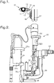
- an ophthalmic microscope system 20 This consists of an illumination system 22 including a short focus projector to project an image of an illuminated slit onto a patient's eye.
- the eye is observed through a binocular microscope 23.
- the focal position of the microscope 23 is at the same position as the focal position of the illumination system 22.
- a support frame 24 In front of the microscope 23 is a support frame 24 with a curved rest 25a for a patient's forehead, and a chin rest 25b for the patient's chin.
- the patient places his head resting against the curved rest 25a and the chin rest 25b; the height of the chin rest 25b can be adjusted so that the patient's eyes are at the level of the microscope 23.
- the microscope 23 is supported on an L-shaped bracket 26, and the illumination system 22 is supported on a shorter L-shaped bracket 27, both the L-shaped brackets 26 and 27 being mounted on a support 28 and being rotatable about a vertical axis. This enables the surgeon to adjust the relative orientations of the illumination and of the microscope 23.
- a plate or platform 29 onto which may be mounted an irrigation system 30 of the invention.
- an irrigation system 30 of the invention comprises a syringe 32 with a plunger 33.
- the plunger 33 can be driven by a linear actuator 34 which is powered by a battery 36.
- the liquid outlet of the syringe 32 is connected by a flexible tube 38 to a transducer unit 40.
- the transducer module 40 defines a flow channel within which is a pressure sensor 42 and a one-way valve 44 adjacent to an outlet 45.
- the outlet 45 is connected to a cannula 46 which, in this example, tapers to a tip 47.
- the transducer module 40 also includes a push-button switch 48. In a modification, the one-way valve 44 is omitted.
- the irrigation system 30 also includes a microprocessor 50 connected to a display module 51 and to a loudspeaker 52.
- the push-button switch 48 provides on and off signals for operation of the irrigation system 30, and these are provided to the microprocessor 50, through a wire 57.
- the microprocessor 50 is also provided with pressure-indicating signals from the pressure sensor 42, through a wire 56, and is provided with flow-rate-indicating signals from the linear actuator 34.
- the microprocessor 50 provides control signals to actuate the linear actuator 34.
- the microprocessor 50 may be connected to a light display instead of, or in addition to, the loudspeaker 52. (The electrical connections are shown schematically.)
- the microprocessor 50 initiates movement of the linear actuator 34.
- the microprocessor 50 monitors both the flow rate and the fluid pressure. In a first mode of operation the pressure rises to a preset value P1, the microprocessor 50 then controls the linear actuator 34 to maintain the pressure at that value P1, and the flow rate F1 is measured for that preset value of pressure.
- the flow rate and pressure gradually increase until a preset flow rate F2 is obtained, the microprocessor 50 then controls the linear actuator 34 to maintain the flow rate at this value F2, and the corresponding pressure P2 is then measured.
- the microprocessor 50 When operating in this mode the microprocessor 50 must also monitor the pressure, to ensure that the pressure does not exceed a threshold P3 at which the patient may experience pain or damage to the tear duct.
- the flow rate is not measured. Instead the flow is set to a predetermined value, for example by supplying a preset voltage to the linear actuator 34. Without monitoring the linear actuator 34 and without measuring the flow rate, the pressure P can be measured. This pressure may be taken as indicative of the flow resistance. The medical professional can readily distinguish between normal values of flow resistance, and abnormal values. If the pressure becomes excessive, the flow may be reduced or cut off.
- the syringe 32 may be a standard syringe, for example of capacity 5 ml or 10 ml.
- the microscope system 20 may provide sufficient space above the plate 29 that a 10 ml syringe can be used.
- a filled 10 ml syringe may be too long, obstructing the view of the eye when fitted vertically on the plate 29.
- the syringe may extend at least partly below the plate 29, for example being inclined from the vertical.
- the tubing 38 is connected to the syringe 32 through a 90°connector, reducing the overall height.
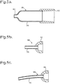
- the cannula 46 needs to be able to seal at the punctum 12 or 13; to be short (to allow easy positioning in the narrow confines around the ophthalmic microscope system 20); to have the maximum possible lumen diameter (to ensure resistance to flow is largely due to the tear duct rather than the cannula 46); to have a short length of narrow diameter (to minimise pressure drop within the cannula 46); and to have the minimum possible outside diameter (to minimise or avoid the need for dilation of the punctum 12 or 13 to allow insertion, avoiding the need for an additional step with patient discomfort and/or risk of damage to the punctum 12 or 13), implying a thin wall.
- the cannula 46 preferably has a broad diameter lumen tapering smoothly to the narrower tip 47 of external diameter no more than 2 mm, for example approximately 0.6 mm, with a constant wall thickness throughout, and a total length of approximately 5-10 mm.
- Alternative designs are possible, for example the provision of a cone or ball at the outer surface towards the tip 47 of the cannula 46, to help it seal to the punctum 12 or 13.
- Other designs of cannula are described below in relation to figures 5a to c.
- the cannula would typically be of stainless steel.
- the tip 47 is sufficiently narrow that no preliminary dilation of the punctum 12 or 13 is required.
- the switch 48 may be activated, either fully on or fully off, on whilst finger pressure applied, off when pressure released.
- the switch 48 may also constitute a valve which, when it is in the "on" position opens the passage to fluid flow; as described above its major role is to provide a signal to the microprocessor 50 to initiate flow of liquid.
- the transducer module 40 includes the pressure sensor 42, which may for example use a piezo-electric transducer, which must be of appropriate sensitivity to provide continuous readouts within the anticipated range of pressures.
- the pressure sensor 42 may be directly exposed to the lumen within the transducer module 40 and so to the liquid flowing through it.
- the cannula 46 is attached to the distal end of the transducer module 40, while the flexible tube 38 is attached to the proximal end (when being used in conjunction with the ophthalmic microscope system 20).
- the mechanism to activate the plunger 33 may be a linear actuator 34 as described above, acting directly as a syringe driver, but other systems to generate liquid flow are possible.
- an electric motor may drive liquid from a reservoir using a pump.
- a screw thread may propel a bracket arranged to move the plunger 33.
- the mechanism may be powered by a battery 36, which may be provided with a recharging circuit (not shown) and means to warn when recharging is required; while as an alternative the irrigation system 30 may instead be powered from the mains.
- the actuator 34 may include other sensors, such as a motor overload detector. The sensing of flow rate may be based on the movement of the plunger 33, or on the speed of the actuator 34, for example using optical sensors, or from measurements on the motor itself, such as armature voltage.
- the linear actuator 34, the battery 36, the microprocessor 50 and the display module 52 are housed within a casing 55 (indicated in broken lines in figure 3 ), which would typically be of a moulded thermoplastic. Electric wires 56 and 57 from the pressure sensor 42 and the switch 48 may therefore be in the form of a flexible lead which connects to the casing 55 with a plug.
- the casing 55 incorporates means to mount the syringe 32, and from which the syringe 32 can be removed.
- the casing 55 may be ergonomically shaped for hand-held operation, preferably with a pen-like grip, and may include a light source 53 to illuminate the punctum 12 or 13 during hand-held operation.
- the irrigation system 30 includes a bracket for connecting the casing 55 on to the plate 29 of the ophthalmic microscope system 20 in the orientation shown in figure 3 , preferably with the outlet of the syringe 32 at the top.
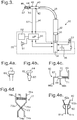
- the irrigation system 30 also includes a punctal occluder, that is to say a clip or plug that can be applied to one punctum 12 or 13 that simply, reliably, safely, painlessly and reversibly closes off the punctum 12 or 13, before liquid is injected into the other punctum 12 or 13.
- a punctal occluder may be a tapered plug 60 with a larger head 61 at one end; the operator would hold the head 61 and insert the tapered plug 60 into the punctum 12 or 13 to prevent any liquid flow.
- the punctal occluder may be a plug 62 with a narrow shaft with a bulbous portion 63, and with a larger head 64 at one end; the operator would hold the head 64, and insert the plug 62 until the bulbous portion 63 had blocked the punctum 12 or 13.
- the punctum or adjacent canaliculus may be closed by externally applied pressure with a clip. This may be achieved by squeezing the canaliculus 14 or 15 between two opposed jaws.
- the jaws may be brought together using a screw thread; but preferably such jaws are mounted resiliently. This squeezing approach may be applied directly to the punctum 12 or 13 itself.
- Suitable occluders are shown in figures 4c, 4d and 4e . In each case the jaws would typically be of a plastic material, whereas the spring would be of a metal such as stainless steel.
- a punctal occluder 65 may comprise a pair of opposed jaws 66a and 66b, one attached to the end of a rod 67 and the other projecting from a sleeve 68 that can slide along the rod 67.
- a projecting finger-plate 69 To the opposite end of the rod 67 is fixed a projecting finger-plate 69, and a second finger-plate 70 projects from the sleeve 68; a compression spring 71 urges the sleeve 68 along the rod 67 so as to urge the jaws 66a and 66b together.
- a punctal occluder 73 may comprise a pair of opposed jaws 74a and 74b at the ends of two pivoted arms 75a and 75b which define finger plates 76a and 76b at their other ends, linked by a pivot pin 77, and with a compression spring 78 arranged to urge the finger plates 76a and 76b apart.
- This occluder 73 resembles a small-scale pair of spring-loaded tongs or scissors.
- a punctal occluder 80 may comprise a pair of opposed jaws 81a and 81b integral with finger plates 82a and 82b, held together by a part-cylindrical spring 83.
- This occluder 80 resembles a small-scale bulldog clip. It is used in a similar way to the occluders 65 and 73 described above.
- the irrigation system 30 is prepared by filling the syringe 32 with a suitable liquid, typically water or saline.
- a suitable liquid typically water or saline.
- the syringe 32 is then fixed on to the casing 55, and the casing 55 mounted on the plate 29; the tube 38 and the transducer module 40 are connected to the syringe 32; the wires 56 and 57 from the transducer module 40 are plugged into the casing 55; and the cannula 46 is connected to the end of the transducer module 40.
- the casing 55 may also be provided with an on/off switch, and a priming/calibration button (not shown). In this case the switch would be switched on, and the system primed and checked. This ensures air is expelled from the system and that the pressure sensor 42 is responding as anticipated.
- the priming function When the priming function is activated, the operator may for example be allowed a few seconds to press the switch 48 to the "on" position. Fluid flow is then initiated at a defined rate or rates, and the output of the pressure sensor 42 is monitored; the pressure rises due to the small diameter of the tip 47. If the pressure or pressures reach values within required limits, the priming and testing is considered satisfactory. This may be indicated by a sound from the speaker 52 (or by a coloured light). The resistance so recorded represents the inherent resistance of the system when not irrigating the tear duct and the system can therefore be calibrated such that this level of resistance represents free flow.
- the operator then uses a punctual occluder to block one punctum of the patient's eye 10, for example the upper punctum 12. While viewing the eye through the microscope 22, the operator with one hand holds the patient's eyelid, and with the other hand holds the transducer module 40, and carefully engages the cannula tip 47 with the other punctum, in this case the lower punctum 13. The operator can then initiate fluid flow by holding down the switch 48, which actuates the linear actuator 34 as described above.
- the microprocessor 50 In a suitable mode of operation, the microprocessor 50 initially assumes that the resistance will have a normal value, and initiates liquid flow at a preset rate. The pressure is monitored using the signals from the sensor 42, and if the pressure is too low the fluid flow is increased, while if the pressure is too high the fluid flow is reduced. Hence the microprocessor 50, using the feedback of pressure values, brings the pressure to a value in a pre-determined range and the fluid flow to a steady state. Damping circuitry in the microprocessor 50 is arranged to avoid wide swings or overshoots, so as to rapidly reach a steady state and thereby minimise the amount of fluid irrigation required. This ensures a more comfortable test for the patient and less need to replenish the fluid in the syringe.
- the microprocessor can deduce the resistance of the patient's tear duct (between the punctum, in this case the lower punctum 13, and the nasal channel 17).
- the flow rate is typically in the range from 5 to 10 ml/min; and the injection pressure might for example be in the range from 10 to 20 cm water, that is 1 to 2 kPa.
- the resistance of the tear duct is around 6.7 kPa.s/ml, although there can be a wide variation between individuals, typically between about 4.4 kPa.s/ml and 9.0 kPa.s/ml.
- the feedback control system however ensures that the irrigation system 30 is able to be used safely and accurately in individuals where the resistance is normal, significantly greater than normal, or where the drainage system is completely obstructed.
- the microprocessor 50 detects that the pressure has exceeded a threshold value, it reduces the flow, or switches off fluid flow completely to avoid discomfort to the patient or damage to the tear duct or to the linear actuator 34.
- the microprocessor 50 may then provide an audible signal through the loudspeaker 52 to indicate that the test has been successful, and switches off the linear actuator 34.
- the irrigation system 30 provides advantages both for the surgeon and for the patient.
- the system 30 provides objective data on lacrimal resistance, and the measurements are made under conditions that are closer to the natural physiological state.
- the measurements are easier, as they can be made using the microscope to provide excellent visibility for inserting the occluder and for inserting the tip 47 of the cannula 46, and for checking for any leaks.
- the measurements are also easier when using the irrigation system 30 hand-held, without the flexible tube 38, as the system is lightweight, providing an ergonomic hand position, and a comparatively short distance from the hand to the tip 47 of the cannula 46. From the patient's perspective the measurements are safer, with less risk of damage to the canaliculi either during insertion or arising from excess pressure; and the measurements are less uncomfortable, as the flow rate and quantity of liquid is less.
- the one-way valve 44 minimises the risk of contamination reaching the flexible tube 38, or the syringe 32 if the flexible tube 38 is not provided. Consequently, after use the transducer module 40 and the cannula 46 would typically be disposable, whereas the other components can be reused without risk of transferring contamination. Alternatively, where no one-way valve 44 is provided, then the syringe 32, flexible tube 38, transducer module 40 and cannula 46 may all be disposable.
- irrigation system 30 may be modified in various ways.
- the cannula 46 may be replaced by a differently-shaped cannula.
- another alternative cannula 94 comprises a stainless steel tube 95 of uniform outside diameter e.g 0.64 mm, and of length for example 4 or 5 mm, inserted into a hub 96 that provides a rounded surface towards the tip of the cannula 94.
- the internal diameter may be around 0.54 mm for a 0.05 mm wall thickness. This size generally does not need dilation before insertion, and the hub 96 may provide the seal to the punctum 12 or 13.
- the tube 95 might have an external diameter 0.57 mm, again with a wall thickness of 0.05 mm. Although the tube 95 is shown as straight, it might instead have a slight curve along its length.
- a cannula 98 which is a modification of the cannula 94, differing in having a longer tube 99 which in this example is slightly curved. This may be around 9-10 mm long, so it would be possible to pass it along the canaliculus 14 or 15 and into the lacrimal sac 16, with the hub 96 sealing at the punctum 12 or 13. This can provide an advantage. Tear duct narrowing is known to most commonly occur in the lacrimal duct 18, and when measuring lacrimal resistance what one really would like to know is the resistance of this part.
- the cannula 98 enables the flow resistance of the lacrimal duct 18 to be measured more precisely, and by comparison with measurements using for example the cannula 94, an objective measurement can be obtained indicating where the narrowing of the tear duct occurs.
- the transducer module 40 may also be modified.
- it may include a mechanical valve to prevent liquid flow, this being actuated by pressing the push-button switch 48 that also provides the electrical signal in the wire 57.
Landscapes
- Health & Medical Sciences (AREA)
- Life Sciences & Earth Sciences (AREA)
- Heart & Thoracic Surgery (AREA)
- Animal Behavior & Ethology (AREA)
- Veterinary Medicine (AREA)
- Engineering & Computer Science (AREA)
- Biomedical Technology (AREA)
- Public Health (AREA)
- General Health & Medical Sciences (AREA)
- Ophthalmology & Optometry (AREA)
- Surgery (AREA)
- Medical Informatics (AREA)
- Biophysics (AREA)
- Physics & Mathematics (AREA)
- Molecular Biology (AREA)
- Vascular Medicine (AREA)
- Nuclear Medicine, Radiotherapy & Molecular Imaging (AREA)
- Anesthesiology (AREA)
- Hematology (AREA)
- Pathology (AREA)
- Pulmonology (AREA)
- Plastic & Reconstructive Surgery (AREA)
- Infusion, Injection, And Reservoir Apparatuses (AREA)
- Prostheses (AREA)
- Measuring Pulse, Heart Rate, Blood Pressure Or Blood Flow (AREA)
Applications Claiming Priority (2)
| Application Number | Priority Date | Filing Date | Title |
|---|---|---|---|
| GB201120771A GB201120771D0 (en) | 2011-12-02 | 2011-12-02 | tear duct resistance measuring system |
| PCT/GB2012/052964 WO2013079959A1 (en) | 2011-12-02 | 2012-11-30 | Tear duct resistance measuring system |
Publications (2)
| Publication Number | Publication Date |
|---|---|
| EP2785239A1 EP2785239A1 (en) | 2014-10-08 |
| EP2785239B1 true EP2785239B1 (en) | 2017-11-22 |
Family
ID=45509076
Family Applications (1)
| Application Number | Title | Priority Date | Filing Date |
|---|---|---|---|
| EP12813416.0A Active EP2785239B1 (en) | 2011-12-02 | 2012-11-30 | Tear duct resistance measuring system |
Country Status (7)
| Country | Link |
|---|---|
| US (2) | US9629540B2 (enExample) |
| EP (1) | EP2785239B1 (enExample) |
| JP (1) | JP6062952B2 (enExample) |
| CN (1) | CN104080395B (enExample) |
| ES (1) | ES2660780T3 (enExample) |
| GB (1) | GB201120771D0 (enExample) |
| WO (1) | WO2013079959A1 (enExample) |
Families Citing this family (9)
| Publication number | Priority date | Publication date | Assignee | Title |
|---|---|---|---|---|
| JP6249755B2 (ja) * | 2013-12-13 | 2017-12-20 | 株式会社トプコン | 眼科装置 |
| WO2016176252A1 (en) * | 2015-04-27 | 2016-11-03 | Khan Taj H | Biosensor canalicular stent |
| US20180193193A1 (en) * | 2015-07-06 | 2018-07-12 | The Regents Of The University Of Colorado, A Body Corporate | Lacrimal drainage system diagnostic implant |
| US20170333009A1 (en) * | 2016-05-19 | 2017-11-23 | Oregon Health & Science University | Instruments used in collecting fluid samples |
| CN107811629A (zh) * | 2017-09-30 | 2018-03-20 | 温州医科大学附属眼视光医院 | 一种基于cs1237芯片、压阻传感器和单片机的压力采集信号的泪道压力检测仪 |
| NL2020558B1 (en) * | 2018-03-09 | 2019-09-13 | D O R C Dutch Ophthalmic Res Center International B V | An ophthalmic pressure control system, a kit of parts and a method |
| WO2020195865A1 (ja) * | 2019-03-26 | 2020-10-01 | ソニー株式会社 | 検眼用アタッチメント、制御装置及び眼科用顕微鏡システム |
| CN112451204B (zh) * | 2019-09-09 | 2024-12-13 | 荷兰眼科研究中心(国际)有限公司 | 眼科压力控制系统、成套部件以及方法 |
| EP4362867A4 (en) * | 2021-06-29 | 2025-03-05 | Visant Medical, Inc. | Method and device for irrigation into the lacrimal puncta |
Family Cites Families (16)
| Publication number | Priority date | Publication date | Assignee | Title |
|---|---|---|---|---|
| US4670006A (en) * | 1984-10-16 | 1987-06-02 | Sinnett Kevin B | Fluid and air infusion device |
| GB8610896D0 (en) * | 1986-05-03 | 1986-06-11 | Needle Industries Ltd | Ophthalmic aspirating/irrigating device |
| US5832930A (en) * | 1994-10-11 | 1998-11-10 | Bloom & Kreten | Clamp for nasolacrimal sac occlusion during administration of ocular medication |
| JP2004507321A (ja) * | 2000-08-29 | 2004-03-11 | アルコン マニュファクチャリング,リミティド | 注入制御システム |
| US20050048099A1 (en) * | 2003-01-09 | 2005-03-03 | Allergan, Inc. | Ocular implant made by a double extrusion process |
| US8016798B2 (en) * | 2003-02-24 | 2011-09-13 | Integrated Sensing Systems, Inc. | Fluid delivery system and sensing unit therefor |
| US7846126B2 (en) * | 2003-07-14 | 2010-12-07 | Abbott Medical Optics, Inc. | System and method for modulated surgical procedure irrigation and aspiration |
| US20050038323A1 (en) * | 2003-08-11 | 2005-02-17 | Knit Ventures, Llc | Tear duct endoscope for medication and sampling |
| SG170816A1 (en) * | 2006-03-31 | 2011-05-30 | Qlt Plug Delivery Inc | Drug delivery methods, structures, and compositions for nasolacrimal system |
| JP2010246573A (ja) * | 2007-08-10 | 2010-11-04 | Saver Inc | 眼内手術装置 |
| US20110015512A1 (en) * | 2008-03-06 | 2011-01-20 | The Regents Of The University Of California | Measuring outflow resistance/facility of an eye |
| US8162919B2 (en) * | 2008-12-08 | 2012-04-24 | Bausch & Lomb Incorporated | Flow control system based on leakage |
| US20100324476A1 (en) * | 2009-06-17 | 2010-12-23 | Mikhail Boukhny | Fluidics control via wireless telemetry |
| EP2467057B1 (en) * | 2009-08-19 | 2020-07-22 | Medline Industries, Inc., | Systems and devices for facilitating access to target anatomical sites or environments |
| US8147467B2 (en) * | 2009-09-24 | 2012-04-03 | Stephen C Chen | Noninvasive lacrimal canalicular occlusion device and method |
| WO2012037428A2 (en) * | 2010-09-16 | 2012-03-22 | The Cleveland Clinic Foundation | Lacrimal drainage manometer and method of use |
-
2011
- 2011-12-02 GB GB201120771A patent/GB201120771D0/en not_active Ceased
-
2012
- 2012-11-30 CN CN201280068814.8A patent/CN104080395B/zh active Active
- 2012-11-30 WO PCT/GB2012/052964 patent/WO2013079959A1/en not_active Ceased
- 2012-11-30 EP EP12813416.0A patent/EP2785239B1/en active Active
- 2012-11-30 US US14/362,306 patent/US9629540B2/en active Active
- 2012-11-30 ES ES12813416.0T patent/ES2660780T3/es active Active
- 2012-11-30 JP JP2014543975A patent/JP6062952B2/ja active Active
-
2017
- 2017-03-27 US US15/470,517 patent/US20170196448A1/en not_active Abandoned
Non-Patent Citations (1)
| Title |
|---|
| HARVARD APPARATUS: "Model 975/2274 Syringe Pump Series User's Manual", 1 November 1995 (1995-11-01), XP055329020, Retrieved from the Internet <URL:http://www.harvardapparatus.co.uk/hapdfs/HAUK_DOCCAT_4/975_2274_Series.pdf> [retrieved on 20161214] * |
Also Published As
| Publication number | Publication date |
|---|---|
| US20140358039A1 (en) | 2014-12-04 |
| WO2013079959A1 (en) | 2013-06-06 |
| JP6062952B2 (ja) | 2017-01-18 |
| CN104080395A (zh) | 2014-10-01 |
| CN104080395B (zh) | 2016-09-21 |
| ES2660780T3 (es) | 2018-03-26 |
| EP2785239A1 (en) | 2014-10-08 |
| US20170196448A1 (en) | 2017-07-13 |
| JP2015505685A (ja) | 2015-02-26 |
| GB201120771D0 (en) | 2012-01-11 |
| US9629540B2 (en) | 2017-04-25 |
Similar Documents
| Publication | Publication Date | Title |
|---|---|---|
| EP2785239B1 (en) | Tear duct resistance measuring system | |
| CA2611330C (en) | Method of testing a surgical system | |
| RU2654606C2 (ru) | Управление давлением в факоэмульсификационной системе | |
| EP1928538B1 (en) | Intraocular pressure control | |
| EP1062958B1 (en) | Software for controlling the operating parameters of a surgical system | |
| ES3024659T3 (en) | Automated viscous fluid control in vitreoretinal surgery | |
| ES2204629T3 (es) | Sistema de control de irrigacion. | |
| US20120215160A1 (en) | Ophthalmic surgical systems having intraocular pressure stabilizing apparatus | |
| BR112015008307B1 (pt) | Método para controlar um sistema cirúrgico tendo um caminho de fluxo de fluido | |
| BRPI0616435B1 (pt) | Cassete cirúrgico | |
| CN105007868A (zh) | 用于在眼科手术期间润湿眼睛的系统和方法 | |
| CA2610868A1 (en) | Method of testing a surgical system | |
| BRPI0612290A2 (pt) | método de controlar refluxo em um sistema microcirúrgico | |
| WO2002026016A2 (en) | Method of operating an infusion control system | |
| JPS6266834A (ja) | 眼内液圧測定用の眼科用器具 | |
| CN120916684A (zh) | 用于眼科手术的集成有压力传感器的手术器械 | |
| JPH02107245A (ja) | 潅流装置 |
Legal Events
| Date | Code | Title | Description |
|---|---|---|---|
| PUAI | Public reference made under article 153(3) epc to a published international application that has entered the european phase |
Free format text: ORIGINAL CODE: 0009012 |
|
| 17P | Request for examination filed |
Effective date: 20140627 |
|
| AK | Designated contracting states |
Kind code of ref document: A1 Designated state(s): AL AT BE BG CH CY CZ DE DK EE ES FI FR GB GR HR HU IE IS IT LI LT LU LV MC MK MT NL NO PL PT RO RS SE SI SK SM TR |
|
| DAX | Request for extension of the european patent (deleted) | ||
| 17Q | First examination report despatched |
Effective date: 20161220 |
|
| RIC1 | Information provided on ipc code assigned before grant |
Ipc: A61B 3/10 20060101AFI20170705BHEP Ipc: A61B 10/00 20060101ALN20170705BHEP Ipc: A61B 5/03 20060101ALN20170705BHEP |
|
| GRAP | Despatch of communication of intention to grant a patent |
Free format text: ORIGINAL CODE: EPIDOSNIGR1 |
|
| INTG | Intention to grant announced |
Effective date: 20170816 |
|
| GRAS | Grant fee paid |
Free format text: ORIGINAL CODE: EPIDOSNIGR3 |
|
| GRAA | (expected) grant |
Free format text: ORIGINAL CODE: 0009210 |
|
| AK | Designated contracting states |
Kind code of ref document: B1 Designated state(s): AL AT BE BG CH CY CZ DE DK EE ES FI FR GB GR HR HU IE IS IT LI LT LU LV MC MK MT NL NO PL PT RO RS SE SI SK SM TR |
|
| REG | Reference to a national code |
Ref country code: GB Ref legal event code: FG4D |
|
| REG | Reference to a national code |
Ref country code: CH Ref legal event code: EP |
|
| REG | Reference to a national code |
Ref country code: IE Ref legal event code: FG4D |
|
| REG | Reference to a national code |
Ref country code: AT Ref legal event code: REF Ref document number: 947606 Country of ref document: AT Kind code of ref document: T Effective date: 20171215 |
|
| REG | Reference to a national code |
Ref country code: DE Ref legal event code: R096 Ref document number: 602012040157 Country of ref document: DE |
|
| REG | Reference to a national code |
Ref country code: CH Ref legal event code: NV Representative=s name: E. BLUM AND CO. AG PATENT- UND MARKENANWAELTE , CH Ref country code: FR Ref legal event code: PLFP Year of fee payment: 6 |
|
| REG | Reference to a national code |
Ref country code: ES Ref legal event code: FG2A Ref document number: 2660780 Country of ref document: ES Kind code of ref document: T3 Effective date: 20180326 |
|
| REG | Reference to a national code |
Ref country code: NL Ref legal event code: MP Effective date: 20171122 |
|
| REG | Reference to a national code |
Ref country code: LT Ref legal event code: MG4D |
|
| REG | Reference to a national code |
Ref country code: AT Ref legal event code: MK05 Ref document number: 947606 Country of ref document: AT Kind code of ref document: T Effective date: 20171122 |
|
| PG25 | Lapsed in a contracting state [announced via postgrant information from national office to epo] |
Ref country code: NO Free format text: LAPSE BECAUSE OF FAILURE TO SUBMIT A TRANSLATION OF THE DESCRIPTION OR TO PAY THE FEE WITHIN THE PRESCRIBED TIME-LIMIT Effective date: 20180222 Ref country code: FI Free format text: LAPSE BECAUSE OF FAILURE TO SUBMIT A TRANSLATION OF THE DESCRIPTION OR TO PAY THE FEE WITHIN THE PRESCRIBED TIME-LIMIT Effective date: 20171122 Ref country code: LT Free format text: LAPSE BECAUSE OF FAILURE TO SUBMIT A TRANSLATION OF THE DESCRIPTION OR TO PAY THE FEE WITHIN THE PRESCRIBED TIME-LIMIT Effective date: 20171122 Ref country code: NL Free format text: LAPSE BECAUSE OF FAILURE TO SUBMIT A TRANSLATION OF THE DESCRIPTION OR TO PAY THE FEE WITHIN THE PRESCRIBED TIME-LIMIT Effective date: 20171122 Ref country code: SE Free format text: LAPSE BECAUSE OF FAILURE TO SUBMIT A TRANSLATION OF THE DESCRIPTION OR TO PAY THE FEE WITHIN THE PRESCRIBED TIME-LIMIT Effective date: 20171122 |
|
| PG25 | Lapsed in a contracting state [announced via postgrant information from national office to epo] |
Ref country code: HR Free format text: LAPSE BECAUSE OF FAILURE TO SUBMIT A TRANSLATION OF THE DESCRIPTION OR TO PAY THE FEE WITHIN THE PRESCRIBED TIME-LIMIT Effective date: 20171122 Ref country code: GR Free format text: LAPSE BECAUSE OF FAILURE TO SUBMIT A TRANSLATION OF THE DESCRIPTION OR TO PAY THE FEE WITHIN THE PRESCRIBED TIME-LIMIT Effective date: 20180223 Ref country code: RS Free format text: LAPSE BECAUSE OF FAILURE TO SUBMIT A TRANSLATION OF THE DESCRIPTION OR TO PAY THE FEE WITHIN THE PRESCRIBED TIME-LIMIT Effective date: 20171122 Ref country code: AT Free format text: LAPSE BECAUSE OF FAILURE TO SUBMIT A TRANSLATION OF THE DESCRIPTION OR TO PAY THE FEE WITHIN THE PRESCRIBED TIME-LIMIT Effective date: 20171122 Ref country code: LV Free format text: LAPSE BECAUSE OF FAILURE TO SUBMIT A TRANSLATION OF THE DESCRIPTION OR TO PAY THE FEE WITHIN THE PRESCRIBED TIME-LIMIT Effective date: 20171122 Ref country code: BG Free format text: LAPSE BECAUSE OF FAILURE TO SUBMIT A TRANSLATION OF THE DESCRIPTION OR TO PAY THE FEE WITHIN THE PRESCRIBED TIME-LIMIT Effective date: 20180222 |
|
| PG25 | Lapsed in a contracting state [announced via postgrant information from national office to epo] |
Ref country code: DK Free format text: LAPSE BECAUSE OF FAILURE TO SUBMIT A TRANSLATION OF THE DESCRIPTION OR TO PAY THE FEE WITHIN THE PRESCRIBED TIME-LIMIT Effective date: 20171122 Ref country code: CY Free format text: LAPSE BECAUSE OF FAILURE TO SUBMIT A TRANSLATION OF THE DESCRIPTION OR TO PAY THE FEE WITHIN THE PRESCRIBED TIME-LIMIT Effective date: 20171122 Ref country code: CZ Free format text: LAPSE BECAUSE OF FAILURE TO SUBMIT A TRANSLATION OF THE DESCRIPTION OR TO PAY THE FEE WITHIN THE PRESCRIBED TIME-LIMIT Effective date: 20171122 Ref country code: SK Free format text: LAPSE BECAUSE OF FAILURE TO SUBMIT A TRANSLATION OF THE DESCRIPTION OR TO PAY THE FEE WITHIN THE PRESCRIBED TIME-LIMIT Effective date: 20171122 Ref country code: EE Free format text: LAPSE BECAUSE OF FAILURE TO SUBMIT A TRANSLATION OF THE DESCRIPTION OR TO PAY THE FEE WITHIN THE PRESCRIBED TIME-LIMIT Effective date: 20171122 |
|
| REG | Reference to a national code |
Ref country code: DE Ref legal event code: R097 Ref document number: 602012040157 Country of ref document: DE |
|
| PG25 | Lapsed in a contracting state [announced via postgrant information from national office to epo] |
Ref country code: PL Free format text: LAPSE BECAUSE OF FAILURE TO SUBMIT A TRANSLATION OF THE DESCRIPTION OR TO PAY THE FEE WITHIN THE PRESCRIBED TIME-LIMIT Effective date: 20171122 Ref country code: RO Free format text: LAPSE BECAUSE OF FAILURE TO SUBMIT A TRANSLATION OF THE DESCRIPTION OR TO PAY THE FEE WITHIN THE PRESCRIBED TIME-LIMIT Effective date: 20171122 Ref country code: LU Free format text: LAPSE BECAUSE OF NON-PAYMENT OF DUE FEES Effective date: 20171130 Ref country code: SM Free format text: LAPSE BECAUSE OF FAILURE TO SUBMIT A TRANSLATION OF THE DESCRIPTION OR TO PAY THE FEE WITHIN THE PRESCRIBED TIME-LIMIT Effective date: 20171122 |
|
| REG | Reference to a national code |
Ref country code: BE Ref legal event code: MM Effective date: 20171130 |
|
| REG | Reference to a national code |
Ref country code: IE Ref legal event code: MM4A |
|
| PG25 | Lapsed in a contracting state [announced via postgrant information from national office to epo] |
Ref country code: MT Free format text: LAPSE BECAUSE OF NON-PAYMENT OF DUE FEES Effective date: 20171130 |
|
| PLBE | No opposition filed within time limit |
Free format text: ORIGINAL CODE: 0009261 |
|
| STAA | Information on the status of an ep patent application or granted ep patent |
Free format text: STATUS: NO OPPOSITION FILED WITHIN TIME LIMIT |
|
| 26N | No opposition filed |
Effective date: 20180823 |
|
| PG25 | Lapsed in a contracting state [announced via postgrant information from national office to epo] |
Ref country code: IE Free format text: LAPSE BECAUSE OF NON-PAYMENT OF DUE FEES Effective date: 20171130 |
|
| PG25 | Lapsed in a contracting state [announced via postgrant information from national office to epo] |
Ref country code: SI Free format text: LAPSE BECAUSE OF FAILURE TO SUBMIT A TRANSLATION OF THE DESCRIPTION OR TO PAY THE FEE WITHIN THE PRESCRIBED TIME-LIMIT Effective date: 20171122 Ref country code: BE Free format text: LAPSE BECAUSE OF NON-PAYMENT OF DUE FEES Effective date: 20171130 |
|
| PG25 | Lapsed in a contracting state [announced via postgrant information from national office to epo] |
Ref country code: HU Free format text: LAPSE BECAUSE OF FAILURE TO SUBMIT A TRANSLATION OF THE DESCRIPTION OR TO PAY THE FEE WITHIN THE PRESCRIBED TIME-LIMIT; INVALID AB INITIO Effective date: 20121130 Ref country code: MC Free format text: LAPSE BECAUSE OF FAILURE TO SUBMIT A TRANSLATION OF THE DESCRIPTION OR TO PAY THE FEE WITHIN THE PRESCRIBED TIME-LIMIT Effective date: 20171122 |
|
| PG25 | Lapsed in a contracting state [announced via postgrant information from national office to epo] |
Ref country code: MK Free format text: LAPSE BECAUSE OF FAILURE TO SUBMIT A TRANSLATION OF THE DESCRIPTION OR TO PAY THE FEE WITHIN THE PRESCRIBED TIME-LIMIT Effective date: 20171122 |
|
| PG25 | Lapsed in a contracting state [announced via postgrant information from national office to epo] |
Ref country code: TR Free format text: LAPSE BECAUSE OF FAILURE TO SUBMIT A TRANSLATION OF THE DESCRIPTION OR TO PAY THE FEE WITHIN THE PRESCRIBED TIME-LIMIT Effective date: 20171122 |
|
| PG25 | Lapsed in a contracting state [announced via postgrant information from national office to epo] |
Ref country code: PT Free format text: LAPSE BECAUSE OF FAILURE TO SUBMIT A TRANSLATION OF THE DESCRIPTION OR TO PAY THE FEE WITHIN THE PRESCRIBED TIME-LIMIT Effective date: 20171122 |
|
| PG25 | Lapsed in a contracting state [announced via postgrant information from national office to epo] |
Ref country code: AL Free format text: LAPSE BECAUSE OF FAILURE TO SUBMIT A TRANSLATION OF THE DESCRIPTION OR TO PAY THE FEE WITHIN THE PRESCRIBED TIME-LIMIT Effective date: 20171122 Ref country code: IS Free format text: LAPSE BECAUSE OF FAILURE TO SUBMIT A TRANSLATION OF THE DESCRIPTION OR TO PAY THE FEE WITHIN THE PRESCRIBED TIME-LIMIT Effective date: 20180322 |
|
| REG | Reference to a national code |
Ref country code: CH Ref legal event code: U11 Free format text: ST27 STATUS EVENT CODE: U-0-0-U10-U11 (AS PROVIDED BY THE NATIONAL OFFICE) Effective date: 20251201 |
|
| PGFP | Annual fee paid to national office [announced via postgrant information from national office to epo] |
Ref country code: DE Payment date: 20251114 Year of fee payment: 14 |
|
| PGFP | Annual fee paid to national office [announced via postgrant information from national office to epo] |
Ref country code: GB Payment date: 20251119 Year of fee payment: 14 |
|
| PGFP | Annual fee paid to national office [announced via postgrant information from national office to epo] |
Ref country code: IT Payment date: 20251114 Year of fee payment: 14 |
|
| PGFP | Annual fee paid to national office [announced via postgrant information from national office to epo] |
Ref country code: FR Payment date: 20251125 Year of fee payment: 14 |
|
| PGFP | Annual fee paid to national office [announced via postgrant information from national office to epo] |
Ref country code: CH Payment date: 20251201 Year of fee payment: 14 |
|
| PGFP | Annual fee paid to national office [announced via postgrant information from national office to epo] |
Ref country code: ES Payment date: 20251216 Year of fee payment: 14 |