EP2784918A1 - Rotating electric machine - Google Patents
Rotating electric machine Download PDFInfo
- Publication number
- EP2784918A1 EP2784918A1 EP11876143.6A EP11876143A EP2784918A1 EP 2784918 A1 EP2784918 A1 EP 2784918A1 EP 11876143 A EP11876143 A EP 11876143A EP 2784918 A1 EP2784918 A1 EP 2784918A1
- Authority
- EP
- European Patent Office
- Prior art keywords
- rotor
- coolant
- pole
- end plate
- electric machine
- Prior art date
- Legal status (The legal status is an assumption and is not a legal conclusion. Google has not performed a legal analysis and makes no representation as to the accuracy of the status listed.)
- Withdrawn
Links
- 239000002826 coolant Substances 0.000 claims abstract description 151
- 238000001816 cooling Methods 0.000 claims abstract description 68
- 239000007788 liquid Substances 0.000 claims abstract description 19
- 230000001105 regulatory effect Effects 0.000 claims description 3
- 238000011176 pooling Methods 0.000 claims description 2
- 230000006698 induction Effects 0.000 description 67
- 239000003921 oil Substances 0.000 description 51
- 230000004907 flux Effects 0.000 description 25
- 239000011347 resin Substances 0.000 description 19
- 229920005989 resin Polymers 0.000 description 19
- 238000004804 winding Methods 0.000 description 9
- 239000000696 magnetic material Substances 0.000 description 7
- 238000003780 insertion Methods 0.000 description 5
- 230000037431 insertion Effects 0.000 description 5
- 229910000831 Steel Inorganic materials 0.000 description 4
- 230000008901 benefit Effects 0.000 description 4
- 238000009826 distribution Methods 0.000 description 4
- 238000003825 pressing Methods 0.000 description 4
- 239000010959 steel Substances 0.000 description 4
- 230000015572 biosynthetic process Effects 0.000 description 3
- 230000000694 effects Effects 0.000 description 3
- 239000002184 metal Substances 0.000 description 3
- 239000003595 mist Substances 0.000 description 3
- 238000003466 welding Methods 0.000 description 3
- 229910000976 Electrical steel Inorganic materials 0.000 description 2
- 238000005299 abrasion Methods 0.000 description 2
- 230000009471 action Effects 0.000 description 2
- 230000007812 deficiency Effects 0.000 description 2
- 230000005611 electricity Effects 0.000 description 2
- 239000000463 material Substances 0.000 description 2
- 241000208202 Linaceae Species 0.000 description 1
- 235000004431 Linum usitatissimum Nutrition 0.000 description 1
- XUIMIQQOPSSXEZ-UHFFFAOYSA-N Silicon Chemical compound [Si] XUIMIQQOPSSXEZ-UHFFFAOYSA-N 0.000 description 1
- 230000005540 biological transmission Effects 0.000 description 1
- 239000003990 capacitor Substances 0.000 description 1
- 238000005520 cutting process Methods 0.000 description 1
- 230000006866 deterioration Effects 0.000 description 1
- 239000012212 insulator Substances 0.000 description 1
- 230000010354 integration Effects 0.000 description 1
- 230000005389 magnetism Effects 0.000 description 1
- 230000005415 magnetization Effects 0.000 description 1
- 238000004519 manufacturing process Methods 0.000 description 1
- 230000004048 modification Effects 0.000 description 1
- 238000012986 modification Methods 0.000 description 1
- 238000000465 moulding Methods 0.000 description 1
- 230000000149 penetrating effect Effects 0.000 description 1
- 230000005855 radiation Effects 0.000 description 1
- 239000004065 semiconductor Substances 0.000 description 1
- 238000000926 separation method Methods 0.000 description 1
- 229910052710 silicon Inorganic materials 0.000 description 1
- 239000010703 silicon Substances 0.000 description 1
- 239000007787 solid Substances 0.000 description 1
- 230000007480 spreading Effects 0.000 description 1
- 238000003892 spreading Methods 0.000 description 1
- 229910001220 stainless steel Inorganic materials 0.000 description 1
- 239000010935 stainless steel Substances 0.000 description 1
- 230000002123 temporal effect Effects 0.000 description 1
Images









Classifications
-
- H—ELECTRICITY
- H02—GENERATION; CONVERSION OR DISTRIBUTION OF ELECTRIC POWER
- H02K—DYNAMO-ELECTRIC MACHINES
- H02K9/00—Arrangements for cooling or ventilating
- H02K9/19—Arrangements for cooling or ventilating for machines with closed casing and closed-circuit cooling using a liquid cooling medium, e.g. oil
- H02K9/197—Arrangements for cooling or ventilating for machines with closed casing and closed-circuit cooling using a liquid cooling medium, e.g. oil in which the rotor or stator space is fluid-tight, e.g. to provide for different cooling media for rotor and stator
-
- H—ELECTRICITY
- H02—GENERATION; CONVERSION OR DISTRIBUTION OF ELECTRIC POWER
- H02K—DYNAMO-ELECTRIC MACHINES
- H02K19/00—Synchronous motors or generators
- H02K19/02—Synchronous motors
- H02K19/10—Synchronous motors for multi-phase current
- H02K19/12—Synchronous motors for multi-phase current characterised by the arrangement of exciting windings, e.g. for self-excitation, compounding or pole-changing
-
- H—ELECTRICITY
- H02—GENERATION; CONVERSION OR DISTRIBUTION OF ELECTRIC POWER
- H02K—DYNAMO-ELECTRIC MACHINES
- H02K1/00—Details of the magnetic circuit
- H02K1/06—Details of the magnetic circuit characterised by the shape, form or construction
- H02K1/22—Rotating parts of the magnetic circuit
- H02K1/32—Rotating parts of the magnetic circuit with channels or ducts for flow of cooling medium
-
- H—ELECTRICITY
- H02—GENERATION; CONVERSION OR DISTRIBUTION OF ELECTRIC POWER
- H02K—DYNAMO-ELECTRIC MACHINES
- H02K11/00—Structural association of dynamo-electric machines with electric components or with devices for shielding, monitoring or protection
- H02K11/04—Structural association of dynamo-electric machines with electric components or with devices for shielding, monitoring or protection for rectification
- H02K11/042—Rectifiers associated with rotating parts, e.g. rotor cores or rotary shafts
-
- H—ELECTRICITY
- H02—GENERATION; CONVERSION OR DISTRIBUTION OF ELECTRIC POWER
- H02K—DYNAMO-ELECTRIC MACHINES
- H02K3/00—Details of windings
- H02K3/04—Windings characterised by the conductor shape, form or construction, e.g. with bar conductors
- H02K3/24—Windings characterised by the conductor shape, form or construction, e.g. with bar conductors with channels or ducts for cooling medium between the conductors
-
- H—ELECTRICITY
- H02—GENERATION; CONVERSION OR DISTRIBUTION OF ELECTRIC POWER
- H02K—DYNAMO-ELECTRIC MACHINES
- H02K5/00—Casings; Enclosures; Supports
- H02K5/04—Casings or enclosures characterised by the shape, form or construction thereof
- H02K5/18—Casings or enclosures characterised by the shape, form or construction thereof with ribs or fins for improving heat transfer
-
- H—ELECTRICITY
- H02—GENERATION; CONVERSION OR DISTRIBUTION OF ELECTRIC POWER
- H02K—DYNAMO-ELECTRIC MACHINES
- H02K9/00—Arrangements for cooling or ventilating
- H02K9/19—Arrangements for cooling or ventilating for machines with closed casing and closed-circuit cooling using a liquid cooling medium, e.g. oil
-
- H—ELECTRICITY
- H02—GENERATION; CONVERSION OR DISTRIBUTION OF ELECTRIC POWER
- H02K—DYNAMO-ELECTRIC MACHINES
- H02K1/00—Details of the magnetic circuit
- H02K1/06—Details of the magnetic circuit characterised by the shape, form or construction
- H02K1/22—Rotating parts of the magnetic circuit
- H02K1/24—Rotor cores with salient poles ; Variable reluctance rotors
-
- H—ELECTRICITY
- H02—GENERATION; CONVERSION OR DISTRIBUTION OF ELECTRIC POWER
- H02K—DYNAMO-ELECTRIC MACHINES
- H02K1/00—Details of the magnetic circuit
- H02K1/06—Details of the magnetic circuit characterised by the shape, form or construction
- H02K1/22—Rotating parts of the magnetic circuit
- H02K1/28—Means for mounting or fastening rotating magnetic parts on to, or to, the rotor structures
-
- H—ELECTRICITY
- H02—GENERATION; CONVERSION OR DISTRIBUTION OF ELECTRIC POWER
- H02K—DYNAMO-ELECTRIC MACHINES
- H02K17/00—Asynchronous induction motors; Asynchronous induction generators
- H02K17/02—Asynchronous induction motors
- H02K17/26—Asynchronous induction motors having rotors or stators designed to permit synchronous operation
Definitions
- Patent Document 2 discloses a rotating electric machine having a stator for generating a rotating magnetic field as an AC flows in a stator wiring, and a rotor having rotor wirings mounted at a plurality of respective positions thereof in a circumferential direction and a diode for rectifying a current flowing in each rotor wiring.
- the electronic device may be mounted on an end plate that constitutes the end surface of the rotor in the axial direction
- the coolant supply path may include a first coolant supply path formed in the shaft and a second coolant supply path formed in the end plate, in which an end portion of the second coolant supply path is open on a surface of the end plate.
- FIG. 2 is a schematic cross sectional view showing a part of the rotor and the stator in the circumferential direction in a rotating electric machine in this embodiment.
- FIG. 3 is a schematic view showing a magnetic flux generated due to an induced current flowing in the rotor coil and flowing in the rotor in the rotating electric machine in this embodiment.
- FIG. 4 shows a rotor coil connected to a diode, and is a drawing corresponding to FIG. 3 .
- one end portions of the N-pole induction coil 28n and of the S-pole induction coil 28s are connected to each other at a connection point R via the first diode 38 and the second diode 40, respectively, of which forward directions are opposite from each other.
- a diode device 41 formed by integrating the first and second diodes 38, 40 in a single resin mold package, to be described later, is used in this embodiment.
- a brim portion 44 for preventing removal of the inductance coils 28n, 28s may be formed on the tip end portion of each salient pole 32n (similar with 32s) so as to project in the two respective sides in the circumferential direction.
- the brim portion 44 is omissible.
- auxiliary salient pole 42 projects from each of the two lateral surfaces of each salient pole 32n, 32s, as described above, it is possible to enlarge the maximum amplitude of a magnetic flux that links with each induction coil 28n, 28, and thus to enlarge variation of the interlinkage magnetic flux, compared to a case where there is no auxiliary salient pole 42, that is, a case in which there is only a space between the adjacent salient poles 32n, 32s in the circumferential direction in each slot 34.
- a magnetic field of each salient pole 32n, 32s reacts with the rotating magnetic field (basic wave component) generated by the stator 12, whereby attraction and repulsion are caused. It is possible to have a torque (a torque corresponding to a magnetic torque) act on the rotor 14 through electromagnetic mutual reaction (attraction and repulsion) between the rotating magnetic field (basic wave component) generated by the stator 12 and the magnetic field of the salient pole 32n, 32s (magnet) as well, and the rotor 14 rotates in synchronism with the rotating magnetic field (basic wave component) generated by the stator 12. In this manner, the rotating electric machine 10 can cause the rotor 14 to function as a motor for generating a driving force (mechanical driving force), utilizing power supplied to the stator coils 20u, 20v, 20w.
- a driving force mechanical driving force
- one end portion of the N-pole common coil 30n of one of the serially connected plurality of common coil pairs C1, the end portion constituting one end portion of the serial connection, is connected to the connection point R
- one end portion of the S-pole common coil 30s of another common coil pair C1 the end portion constituting the other end portion of the serial connection, is connected to the other ends of the N-pole induction coil group Kn and of the S-pole induction coil group Ks, opposite from the connection point R.
- the total number of diodes mounted on the rotor can be reduced to two, that is, the first diode 38 and the second diode 40, which can reduce costs and the number of assembly steps.
- the above described is a basic structure of the rotating electric machine 10 having the rotor 14 in this embodiment, and an effect thereof.
- a structure including a plurality of rotor core elements arranged at a plurality of respective positions in the circumferential direction is employed as the rotor 14, and moreover, a specific structure described below is also employed in order to reduce magnetic resistance in a magnetic path in which many magnetic fluxes generated in the stator 12 run and also to improve performance of the rotating electric machine 10.
- FIGs 7 and 8 a specific structure of the rotor 14 will be described, referring to FIGs 7 and 8 , in which elements similar to those shown in FIGs 1 to 6 are given the same reference numerals.
- each core element 54, 56 the induction coil 28n (or 28s) is wound on the outer side of the diagonally projecting portion 78 in the radial direction, and the common coil 30n (or 30s) is wound on the inner side of the diagonally projecting portion 78 in the radial direction.
- Each coil 28n, 28s, 30n, 30s may be set to be wound around the respective core element 54, 56 before connecting the core elements 54, 55 to each other by a connection pin 86 or after connecting the core elements 54, 56 to each other by a connection pin 86 and before assembled to the shaft 25.
- the rotor 14a, 14b shown in FIGs 9 and 10 may be formed by cutting electromagnetic steel sheets into an annular shape through stamping, then stacking in the axial direction, and connecting by means of caulking, welding, or the like, for integration, rather than by connecting a plurality of separate core elements 54, 56 in the circumferential direction.
- the position in the circumferential direction of the rotor core fixed to the shaft can be determined through key fitting, pressure insertion, tight fitting, or the like.
- the end plates 26a, 26b may be simply in contact with the rotor core 24 or the like, or sandwich the rotor core 24 or the like from the respective two sides of the rotor core 24 in the axial direction.
- the end plate 26a, 26b may be a simple annular plate provided apart from the rotor core 24 outward in the axial direction.
- the diode device 41 is fitted and placed in the mounting slot 94 and fixed by a screw or the like, for example, while abutting on the abutment wall portion 93 in a position outside in the radial direction.
- six mounting slots 94 are formed, and a diode device 41 is placed in each mounting slot 94.
- the diode device 41 is provided contacting the abutment wall portion 93 in a position outside in the radial direction, it is possible to reliably hold or support the diode device 41 against a centrifugal force that acts on while the rotor 14 is rotating
- coolant discharge outlet 98 is formed between the diode devices 41
- two coolant discharge outlets 98 may be formed between the diode devices 41.
- Another coolant supply path 97 communicating with the coolant supply path 96 of the shaft 25 is formed in the end plate 26a so as to penetrate.
- the coolant supply path 97 is connected to the coolant discharge outlet 98 that is open on the end wall portion 92.
- the end portion itself of the coolant supply path 97 that is open on the end wall portion 92 makes the coolant discharge outlet 98.
- the formation position, size, and shape of the coolant discharge outlet 102 may be desirably set such that a desired amount of cooling oil is discharged from the coolant discharge outlet 98 and flows outward in the radial direction due to a centrifugal force so that preferable cooling performance can be obtained.
- cooling oil from the coolant path 89 of the shaft 25 positioned inside in the radial direction relative to the diode device 41 mounted on the end plate 26a is discharged from the coolant discharge outlet 98 of the end plate 26a via the coolant supply paths 96, 97 due to a centrifugal force or the like of the rotating rotor 14, and flows outward in the radial direction on the outer surface of the end wall portion 92 of the end plate 26a to be supplied to around the diode device 41.
- FIGs 15 to 19 An example including a different structure for cooling the diode device mounted on the rotor by cooling oil is described referring to FIGs 15 to 19 .
- a structure different from that in the above-described embodiment is mainly described here, and structures identical to those in the above are given the same reference numerals and not described again.
- FIG. 15 shows another example in which a coolant discharge outlet is formed on the shaft, and is a drawing corresponding to FIG. 14 .
- the position where the coolant supply path 96 is formed on the shaft 25 is different. That is, the coolant discharge outlet 98, or an end portion of the coolant supply path 96, is formed open on the surface of the shaft 25.
- the coolant path 104 may be positioned displaced in the circumferential direction relative to the diode device 41 when viewed from the axial direction, as long as the coolant path 104 is positioned between the diode device 41 and the coils 28n, 28s, 30n, 30s in the axial direction.
- a diode device or a rectifier that is a separate member is mounted on the end plate provided to the end portion of the rotor core by a screw or the like, this is not limiting.
- a diode device made of a semiconductor device and integrally formed with or built in the end plate may be used.
Landscapes
- Engineering & Computer Science (AREA)
- Power Engineering (AREA)
- Physics & Mathematics (AREA)
- Thermal Sciences (AREA)
- Synchronous Machinery (AREA)
- Iron Core Of Rotating Electric Machines (AREA)
- Motor Or Generator Cooling System (AREA)
Abstract
Description
- The present invention relates to a rotating electric machine having a stator for generating a rotating magnetic field and a rotor having a coil wound therearound.
- Conventionally, Japanese Utility Model Laid-open Publication No.
Hei 5-29275 - Further, Japanese Patent Laid-open Publication No.
2011-41433 -
- [Patent Document 1] Japanese Utility Model Laid-open Publication No.
Hei 5-29275 - [Patent Document 2] Japanese Patent Laid-open Publication No.
2011-41433 - In a rotating electric machine, such as a generator and a motor disclosed in Patent Documents 1 and 2, an electronic device, such as a diode or the like, that rotates together with the rotor generates heat upon application of electricity. Therefore, it is desirable that the electronic device mounted on the rotor is sufficiently cooled by liquid coolant in order to maintain preferable performance of the electronic device.
- However, when liquid coolant is supplied to the electronic device on the rotating rotor from the side of the stator mounted outside the rotor in the radial direction so as to surround the rotor, it may not be possible to sufficiently cool the electronic device due to being hindered by a member for holding the electronic device from the outside in the radial direction and/or a centrifugal force caused by the rotor.
- An object of the present invention is to provide a rotating electric machine capable of sufficiently cooling an electronic device mounted on a rotor by liquid coolant.
- A rotating electric machine according to the present invention includes a stator for generating a rotating magnetic field; a rotatable rotor placed opposed to the stator; an electronic device connected to a coil wound around the rotor, for rotating together with the rotor; and a cooling structure for cooling the electronic device with liquid coolant supplied from the inside in a radial direction relative to the electronic device.
- In the rotating electric machine according to the present invention, the cooling structure may have a coolant path formed in a shaft for rotatably supporting the rotor and a coolant supply path for supplying the liquid coolant flowing in the coolant path to the outside of the shaft.
- In the rotating electric machine according to the present invention, the electronic device may include a plurality of electronic devices placed on an end surface of the rotor in an axial direction at intervals in a circumferential direction, and an end portion of the coolant supply path may be open between the electronic devices in the circumferential direction.
- Further, with the rotating electric machine according to the present invention, the electronic device may be mounted on an end plate that constitutes the end surface of the rotor in the axial direction, and the coolant supply path may include a first coolant supply path formed in the shaft and a second coolant supply path formed in the end plate, in which an end portion of the second coolant supply path is open on a surface of the end plate.
- Further, with the rotating electric machine according to the present invention, the electronic device may be mounted on an end plate that constitutes an end surface of the rotor in an axial direction, and the coolant supply path may be formed in the shaft to supply the liquid coolant from the coolant path to the outside of the shaft, in which an end portion of the coolant supply path is open on a surface of the shaft.
- Further, with the rotating electric machine according to the present invention, the surface of the end plate onto which the liquid coolant is supplied from the coolant supply path may be inclined outward in the axial direction relative to the radial direction.
- Further, with the rotating electric machine according to the present invention, the electronic device may be mounted on an end plate that constitutes an end surface of the rotor in an axial direction, and the coolant supply path may continue to an outer circumferential surface of the end plate in a position between the electronic device and the coil via a path formed in the end plate.
- In this case, a heat discharge fin may be formed on an inside wall surface of the path on a back surface side of the electronic device.
- Further, with the rotating electric machine according to the present invention, the electronic device may be mounted on an end plate that constitutes an end surface of the rotor in an axial direction, an opening on an end portion of the coolant supply path may be positioned farther inward in the axial direction from an end surface of the end plate in the axial direction, and a cover member for covering at least an outer circumferential portion may be provided to the end surface of the end plate in the axial direction.
- In this case, a coolant discharge outlet for regulating the amount of coolant pooled in a coolant sump for pooling the liquid coolant discharged from a coolant discharge outlet and flowing outward in the radial direction may be formed on an outer circumferential portion of the cover member.
- According to the rotating electric machine according to the present invention, liquid coolant supplied to an electronic device from the inside relative thereto in the radial direction flows outward in the radial direction due to a centrifugal force or the like caused by the rotating rotor to be supplied to the circumference of the electronic device, so that the electronic device that generates heat upon application of current can be sufficiently cooled.
-
-
FIG. 1 is a cross sectional view showing a rotating electric machine according to one embodiment of the present invention; -
FIG. 2 is a cross sectional view schematically showing a part of a rotor and stator in a circumferential direction in the rotating electric machine in this embodiment; -
FIG. 3 schematically shows a a magnetic flux generated due to induced current flowing in a rotor coil, flowing into the rotor in the rotating electric machine in this embodiment; -
FIG. 4 shows a rotor coil connected to a diode, and is a drawing corresponding toFIG. 3 ; -
FIG. 5 shows an equivalent circuit of a connection circuit of a plurality of coils wound around two salient poles adjacent in the circumferential direction of the rotor in this embodiment; -
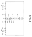
FIG. 6 shows an example in which fewer diodes are connected to the rotor coil, and is a drawing corresponding toFIG. 5 ; -
FIG. 7 is a cross sectional view along the line A-A in the rotor shown inFIG. 1 ; -
FIG. 8 is an enlarged view of the part B inFIG. 7 ; -
FIG. 9 shows a modified example in which diodes are connected to the respective rotor coils wound around the respective salient poles of the rotor; -
FIG. 10 shows an example in which the rotor coil is connected to fewer diodes, and is a drawing corresponding toFIG. 9 ; -
FIG. 11 shows an example of an end surface of the rotor in the axial direction; -
FIG. 12 shows another example of the end surface of the rotor in the axial direction; -
FIG. 13 is a cross sectional view along the line C-C inFIG. 11 ; -
FIG. 14 is a cross sectional view along the line D-D inFIG. 11 ; -
FIG. 15 shows another example in which a coolant discharge outlet is formed in a shaft, and is a drawing corresponding toFIG. 14 ; -
FIG. 16 shows still another example in which a coolant discharge outlet is formed outside the rotor, and is a drawing corresponding toFIG. 14 -
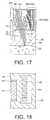
FIG. 17 shows still another example in which a coolant path is formed in an end plate, and is a drawing corresponding toFIG. 14 ; -
FIG. 18 is a cross sectional view along the line E-E inFIG. 17 ; and -
FIG. 19 shows an example in which an electronic device is covered by mold resin and coolant is supplied to the top of the mold resin, and is a drawing corresponding toFIG. 13 . - In the following, an embodiment of the present invention will be described using the drawings.
FIGs 1 to 5 ,7 , and8 show an embodiment of the present invention.FIG. 1 is a schematic cross sectional view showing a part of a rotating electric machine having a rotating electric machine rotor according to this embodiment. As shown inFIG. 1 , a rotatingelectric machine 10 functions as a motor or a generator, and has acylindrical stator 12 fixed to a casing (not shown) and arotor 14 mounted inside in the radial direction relative to thestator 12 at a predetermined space away from thestator 12 so as to be opposed to and rotatable relative to thestator 12. Note that a "radial direction" refers to a radiation direction orthogonal to the rotation center axis of the rotor 14 (which is similarly applied throughout this specification and claims unless stated otherwise). - The
stator 12 has astator core 16 made of magnetic material, andstator coils stator core 16. Therotor 14 has arotor core 24 made of magnetic material, ashaft 25 inserted and fixed at the center of therotor core 24, and twoend plates rotor core 24 in the axial direction. - The
rotor 14 has a plurality of rotor coils, namely, an N-pole induction coil 28n, an S-pole induction coil 28s, an N-polecommon coil 30n, and an S-polecommon coil 30s, mounted on therotor core 24, afirst diode 38 connected to the N-pole induction coil 28n, and asecond diode 40 connected to the S-pole induction coil 28s. - Initially, a basic structure of the rotating
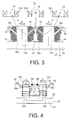
electric machine 10 will be described, usingFIGs 2 to 5 , and a detailed structure of therotor 14 will be thereafter described.FIG. 2 is a schematic cross sectional view showing a part of the rotor and the stator in the circumferential direction in a rotating electric machine in this embodiment.FIG. 3 is a schematic view showing a magnetic flux generated due to an induced current flowing in the rotor coil and flowing in the rotor in the rotating electric machine in this embodiment.FIG. 4 shows a rotor coil connected to a diode, and is a drawing corresponding toFIG. 3 . - As shown in
FIG. 2 , thestator 12 has astator core 16. A plurality ofteeth 18 are formed at a plurality of respective positions in the circumferential direction on the inner circumferential surface of thestator core 16 so as to project inward in the radial direction (that is, toward the rotor 14), with aslot 22 resultantly formed between theteeth 18. Thestator core 16 is made of magnetic material, such as a stacked body of metal sheets, such as electromagnetic steel sheets having magnetism, such as a silicon steel sheet, or the like. The plurality ofteeth 18 are equidistantly arranged in the circumferential direction around the rotation center axis, or the rotation axis of therotor 14. A "circumferential direction" refers to a direction along a circle defined with the rotation center axis of therotor 14 as the center (which is similarly applicable throughout this specification and claims unless otherwise stated). - The stator coils 20u, 20v, 20w of the respective phases run in the
respective slots 22, and are wound around therespective teeth 18 of thestator core 16 in a short-pitch concentrated winding manner. The stator coils 20u, 20v, 20w are wound around theteeth 18, as described above, so that a magnetic pole is formed. Then, by causing AC of a plurality of phases to flow into thestator coils teeth 18 arranged in the circumferential direction are magnetized, whereby a rotating magnetic field that rotates in the circumferential direction is generated in thestator 12. - Note that the
stator coils teeth 18 of thestator 12, and may be wound in a toroidal winding manner, for example, in which stator coils of a plurality of phases are wound around an annular portion of thestator core 16, which is apart from theteeth 18, at a plurality of respective positions in the circumferential direction to generate a rotating magnetic field in thestator 12. - The rotating magnetic field generated on the
teeth 18 acts on therotor 14 from the tip end surface of the teeth. In the example shown inFIG. 2 , threeteeth 18 wound by therespective stator coils - Meanwhile, the
rotor 14 has arotor core 24 made of magnetic material and a plurality of rotor coils, namely, an N-pole induction coil 28n, an N-polecommon coil 30n, an S-pole induction coil 28s, and an S-polecommon coil 30s. Therotor core 24 has an N-pole formedsalient pole 32n and an S-pole formedsalient pole 32s, which are a plurality of magnetic poles formed on the outer circumferential surface thereof at a plurality of respective positions in the circumferential direction so as to project outward (that is, toward the stator 13) in the radial direction, and are main salient poles. - The N-pole formed
salient pole 32n and the S-pole formedsalient pole 32s are arranged alternately at an interval in the circumferential direction of therotor core 24 so as to be opposed to thestator 12. Arotor yoke 33, or the annular portion of therotor core 24, and the plurality ofsalient poles salient pole 32n and the S-pole formedsalient pole 32s have an identical shape and size. - In more detail, two N-pole rotor coils, namely, the N-pole
common coil 30n and the N-pole induction coil 28n, are wound around each of the N-pole formedsalient poles 32n, or every other salient poles formed on therotor 14 in the circumferential direction, in the concentrated winding manner. Moreover, in therotor 14, two S-pole rotor coils, namely, the S-polecommon coil 30s and the S-pole induction coil 28s, are wound around each of the S-pole formedsalient poles 32s, or every other salient pole formed on therotor 14 in the circumferential direction adjacent to the respective N-pole formedsalient poles 32n, in the concentrated winding manner. In view of the radial direction of therotor 14, the respectivecommon coils pole induction coils - As shown in
FIG. 3 , therotor 14 has aslot 34 defined between the adjacentsalient poles slots 34 are formed at intervals on therotor core 24 in the circumferential direction around the rotation axis of therotor 14. Therotor core 24 is fit and fixed outside in the radial direction relative to the shaft 25 (seeFIG. 1 ), which serves as the rotation axis. - Each N-
pole induction coil 28n is wound around each N-pole formedsalient pole 32n on a side closer to the tip end thereof, that is, on a side closer to thestator 12, than the N-polecommon coil 30n. Meanwhile, the S-pole induction coil 28s is wound around each S-pole formedsalient pole 32s on a side closer to the tip end thereof, that is, on a side closer to thestator 12, than the S-polecommon coil 30s. - Note that, as shown in
FIG. 3 , theinduction coils common coils salient poles FIG. 3 ) in the radial direction of thesalient pole 32n (or 32s) are arranged in a plurality of layers in the circumferential direction (the left-right direction inFIG. 3 ) of thesalient pole 32n (or 32s). Further, theinduction coils salient poles salient poles - As shown in
FIGs 4 and5 , assuming that two adjacentsalient poles rotor 14 make a pair, one end portion of the N-pole induction coil 28n wound around one N-pole formedsalient pole 32n in each pair and one end portion of the S-pole induction coil 28s wound around the S-pole formedsalient pole 32s in that pair are connected to each other via two electronic devices that are rectifying elements, namely, afirst diode 38 and asecond diode 40.FIG. 5 shows an equivalent circuit of a connection circuit of the plurality ofcoils salient poles rotor 14 in this embodiment. As shown inFIG. 5 , one end portions of the N-pole induction coil 28n and of the S-pole induction coil 28s are connected to each other at a connection point R via thefirst diode 38 and thesecond diode 40, respectively, of which forward directions are opposite from each other. Note that adiode device 41 formed by integrating the first andsecond diodes - Although a case in which an electronic device connected to the
coils rotor core 24 is a diode is described in this embodiment, this is not limiting. The electronic device may be a rectifier (for example, a thyristor, a transistor, or the like) having a function for rectifying a current flowing in a coil, or an electronic device, such as a resistor, capacitor, or the like, may be used together with a rectifier, such as a diode or the like. - As shown in
FIGs 4 and5 , one end portion of the N-polecommon coil 30n wound around the N-pole formedsalient pole 32n in each pair is connected to one end portion of the S-polecommon coil 30s wound around the S-pole formedsalient pole 32s in that pair. The N-polecommon coil 30n and the S-polecommon coil 30s are serially connected to each other, thereby constituting a common coil set 36. Further, the other end portion of the N-polecommon coil 30n is connected to the connection point R, and the other end portion of the S-polecommon coil 30s is connected to the other end portions of the N-pole induction coil 28n and the S-pole induction coil 28s on the opposite side from the connection point R. The winding center axis of each of theinduction coils common coils FIG. 2 ). Note that each of theinduction coils common coils salient pole 32n (or 32s) via an insulator (not shown) made of resin or the like and having an electrically insulating property. - In such a structure, a rectified current flows into the N-
pole induction coil 28n, the S-pole induction coil 28s, the N-polecommon coil 30n, and the S-polecommon coil 30s, whereby the respectivesalient poles FIG. 3 , thestator 12 generates a rotating magnetic field due to an AC flowing in thestator coils - In more detail, distribution of a magnetomotive force that generates a rotating magnetic field in the
stator 12 does not show a sine wave distribution (containing a basic wave alone) due to the disposition of thestator coils stator core 16 defined by theteeth 18 and the slots 22 (FIG. 2 ), but shows a distribution containing a harmonic component. In particular, with concentrated winding, the amplitude level of a harmonic component generated in the magnetomotive force distribution of thestator 12 increases because thestator coils stator coils stator coils stator core 16 is referred to as a spatial harmonic wave. - When the rotating magnetic field containing a spatial harmonic component acts on the
rotor 14 from thestator 12, a leakage magnetic flux leaking into the space between thesalient poles rotor 14 varies due to variation of the magnetic flux of the spatial harmonic. With the above, an induced electromotive force is generated in at least either of theinduction coil 28n or theinduction coil 28s shown inFIG. 3 . - The
induction coil salient pole stator 12, mainly has a function for generating an induced current. Meanwhile, thecommon coil stator 12 mainly has a function for magnetizing thesalient pole FIG. 5 , the sum of the current flowing in theinduction coils salient poles FIGs 2 to 4 ) makes a current flowing in each of thecommon coils common coils common coils salient poles - When an induced electromotive force is generated in each
induction coil diode pole induction coil 28n, the S-pole induction coil 28s, the N-polecommon coil 30n, and the S-polecommon coil 30s, whereby thesalient pole common coil salient pole - As shown in
FIG. 4 , the N-pole induction coil 28n and the N-polecommon coil 30n and the S-pole induction coil 28s and the S-polecommon coil 30s, adjacent to each other in the circumferential direction, are opposite in the winding direction, and therefore, the adjacentsalient poles salient pole 32n wound by the N-pole induction coil 28n and the N-polecommon coil 30n, and an S pole is generated at the tip end of the S-pole formedsalient pole 32s wound by the S-pole induction coil 28s and the S-polecommon coil 30s. Therefore, an N pole and an S pole are alternately placed in the circumferential direction of therotor 14. That is, therotor 14 is formed such that an N pole and an S pole are alternately formed in the circumferential direction thereof as the harmonic component contained in the magnetic field generated in thestator 12 intersects. - In this embodiment, the
rotor 14 includes an auxiliarysalient pole 42 projecting from each of the two lateral surfaces in the circumferential direction of each of thesalient poles salient pole 42 is a magnetic plate formed on each of the two lateral surfaces of eachsalient pole FIGs 3, 4 ) so as to project from each of a plurality of positions in the axial direction (from the front to rear surfaces ofFIGS 3 and 4 ) in a direction inclined relative to the circumferential direction. For example, in the example shown, the auxiliarysalient pole 42 is formed in a middle portion in the radial direction on each of the two lateral surfaces of eachsalient pole salient poles 42 project from between the N-pole induction coil 28n and the N-polecommon coil 30n and also between the S-pole induction coil 28s and the S-polecommon coil 30s on each of the two lateral surfaces of eachsalient pole salient pole 42 is magnetically connected to a correspondingsalient pole - A plurality of auxiliary
salient poles 42 projecting from the respective opposedsalient poles same slot 34 may or may not be mechanically connected to each other. InFIGs 3 and 4 , the auxiliarysalient pole 42 of the N-pole formedsalient pole 32n and the auxiliarysalient pole 42 of the S-pole formedsalient pole 32s arranged in thesame slot 34 are not mechanically connected to each other. That is,FIGs 3 and 4 schematically show the auxiliarysalient poles 42 in magnetic disconnection. The auxiliarysalient pole 42 is made of the same magnetic material as that of thesalient pole - The
induction coil 28n (or 28s) and thecommon coil 30n (or 30s) wound around eachsalient pole 32n (or 32s) are separated from each other by the auxiliarysalient pole 42 in acorresponding slot 34. That is, theinduction coils common coils salient poles 32, , 32s are connected to each other at a position or positions apart from the auxiliarysalient poles 42, such as, on one or bothe coil end sides (not shown) or the like, more outward than the end surface of therotor core 24 in the axial direction. - As shown in
FIG. 8 to be described later, abrim portion 44 for preventing removal of theinductance coils salient pole 32n (similar with 32s) so as to project in the two respective sides in the circumferential direction. Thebrim portion 44, however, is omissible. - In the rotating
electric machine 10 having the rotor 14 (FIG. 2 ), a rotating magnetic field (basic wave component) generated on the teeth 18 (FIG. 2 ) due to an AC of three phases flowing in thestator coils rotor 14, and thesalient poles teeth 18 such that magnetic resistance of therotor 14 becomes smaller. This makes a torque (reluctance torque) act on therotor 14. - When the rotating magnetic field containing a spatial harmonic component generated on the
teeth 18 links with eachinduction coil rotor 14, an induced electromotive force is generated in theinduction coil rotor 14 due to the spatial harmonic component. A current flowing into eachinduction coil respective diode - The DC current rectified in each
diode induction coil common coil salient pole respective induction coils diodes salient poles - Moreover, as the auxiliary
salient pole 42 is formed on each of the two lateral surfaces of eachsalient pole FIG. 3 , when a case is assumed in which a q-axial magnetic flux, or a magnetic flux of a spatial second-order spatial harmonic, flows as a magnetomotive force of thestator 12 from thestator 12 to therotor 14 in the directions indicated by the broken arrows α, β inFIG. 3 , for example, it is possible, with the auxiliarysalient pole 42, to have many magnetic fluxes link with theinduction coils teeth 18 of thestator 12 to somesalient poles salient poles 42 and further from somesalient poles stator 12 and therotor 14, and therefore, it is possible to have many magnetic fluxes link with theinduction coils - While the direction and size of the q-axial magnetic flux vary during one electric cycle, it is possible to enlarge variation of the interlinkage magnetic flux of the
inductance coil induction coil teeth 18 of thestator 12 via the S-pole auxiliarysalient pole 42 to the S-pole formedsalient pole 32s, as indicated by the broken arrow β inFIG. 3 , and a magnetic flax tends to flow in such a direction that makes the S-pole formedsalient pole 32s become an N pole. In this case, an induced current tends to flow into the S-pole induction coil 28s in such a direction that blocks that flow, and the flow of the induced current is not blocked by the second diode 40 (seeFIG. 4 ). That is, as indicated by the solid arrow inFIG. 3 , a magnetic flux due to an induced current, directed from the S-pole formedsalient pole 32s via therotor yoke 33 of therotor core 24 to the N-pole formedsalient pole 32n, flows. - Meanwhile, there is a case in which a q-axial magnetic flux flows opposite from the above, that is, in an opposite direction from the direction indicated by the broken arrow α in
FIG. 3 , that is, from theteeth 18 of thestator 12 via the N-pole formedsalient pole 32n to the auxiliarysalient pole 42, and a magnetic flux tends to flow in such a direction that makes the N-pole formedsalient pole 32n become an S pole. In this case, an induced current tends to flow into the N-pole induction coils 28n in such a direction that blocks that flow. That flow of the induced current is not blocked by the first diode 38 (seeFIG. 4 ), and causes a current to flow in such a direction that makes the N-pole formedsalient pole 32n become an N pole. In this case as well, a magnetic flux due to an induced current, directed from the S-pole formedsalient pole 32s via therotor yoke 33 to the N-pole formedsalient pole 32n, flows. As a result, eachsalient pole 32n is magnetized into an N pole and eachsalient pole 32s is magnetized into an S pole. - As the auxiliary
salient pole 42 projects from each of the two lateral surfaces of eachsalient pole induction coil 28n, 28, and thus to enlarge variation of the interlinkage magnetic flux, compared to a case where there is no auxiliarysalient pole 42, that is, a case in which there is only a space between the adjacentsalient poles slot 34. - A magnetic field of each
salient pole stator 12, whereby attraction and repulsion are caused. It is possible to have a torque (a torque corresponding to a magnetic torque) act on therotor 14 through electromagnetic mutual reaction (attraction and repulsion) between the rotating magnetic field (basic wave component) generated by thestator 12 and the magnetic field of thesalient pole rotor 14 rotates in synchronism with the rotating magnetic field (basic wave component) generated by thestator 12. In this manner, the rotatingelectric machine 10 can cause therotor 14 to function as a motor for generating a driving force (mechanical driving force), utilizing power supplied to thestator coils - In this embodiment, a case is described in which two adj acent
salient poles induction coils salient poles diodes diodes salient poles induction coils salient poles rotor 14 are connected to one another, and only twodiodes FIG. 6 shows a modified example in which the number of diodes connected to the rotor coils is reduced, and is a drawing corresponding toFIG. 5 . - In the modified example shown in
FIG. 6 , the plurality of N-pole induction coils 28n wound around every other respective salient pole arranged in the circumferential direction of the rotor, namely, all N-pole formedsalient poles 32n (seeFIG. 3 ), on the tip end side thereof are serially connected to each other in the structure shown inFIGs 3 and 4 , to thereby form an N-pole induction coil group Kn, while the plurality of S-pole induction coils 28s wound around every other respective salient pole arranged in the circumferential direction of the rotor, namely, all S-pole formedsalient poles 32s (seeFIG. 3 ), on the tip end side thereof are serially connected to each other, to thereby form an S-pole induction coil group Ks. One end portion of the N-pole induction coil group Kn is connected to one end portion of the S-pole induction coil group Ks at a connection point R via thefirst diode 38 and thesecond diode 40, respectively, of which forward directions are opposite to each other. - In a case where two adjacent salient poles in the circumferential direction of the rotor, namely, the N-pole formed
salient pole 32n and S-pole formedsalient pole 32s (seeFIG. 3 ), make one pair, the N-polecommon coil 30n and the S-polecommon coil 30s in each pair are serially connected to each other, to thereby form a common coil pair C1, and all common coil pairs C1 relevant to all respectivesalient poles common coil 30n of one of the serially connected plurality of common coil pairs C1, the end portion constituting one end portion of the serial connection, is connected to the connection point R, and one end portion of the S-polecommon coil 30s of another common coil pair C1, the end portion constituting the other end portion of the serial connection, is connected to the other ends of the N-pole induction coil group Kn and of the S-pole induction coil group Ks, opposite from the connection point R. In this structure, different from the structure shown inFIGs 4 and5 , the total number of diodes mounted on the rotor can be reduced to two, that is, thefirst diode 38 and thesecond diode 40, which can reduce costs and the number of assembly steps. - The above described is a basic structure of the rotating
electric machine 10 having therotor 14 in this embodiment, and an effect thereof. In this embodiment, a structure including a plurality of rotor core elements arranged at a plurality of respective positions in the circumferential direction is employed as therotor 14, and moreover, a specific structure described below is also employed in order to reduce magnetic resistance in a magnetic path in which many magnetic fluxes generated in thestator 12 run and also to improve performance of the rotatingelectric machine 10. Below, a specific structure of therotor 14 will be described, referring toFIGs 7 and8 , in which elements similar to those shown inFIGs 1 to 6 are given the same reference numerals. -
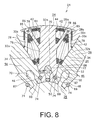
FIG. 7 is a cross sectional view of therotor 14 along the line A-A inFIG. 1 .FIG. 8 is an enlarged view of the part B inFIG. 7 . As shown inFIG. 7 , therotor 14 in this embodiment has therotor core 24 and theshaft 25 fitted and fixed at the center of therotor core 24. - The
shaft 25 has a plurality of outsideconvex portions 46 formed at a plurality of respective positions in the circumferential direction on the outer circumferential surface thereof so as to project in the radial direction. As shown inFIG. 8 , all outsideconvex portion 46 have the same shape in a cross section orthogonal to the axial direction and long in the axial direction. That is, each outsideconvex portion 46 has a shaft-side root portion 48 having a smaller width in the circumferential direction and a shaft-sidetip end portion 50 connected to the shaft-side root portion 48 and having a larger width in the circumferential direction than the width of the shaft-side root portion 48 in the circumferential direction. The shaft-sidetip end portion 50 has a substantially oval cross section. The shaft-sidetip end portion 50 has awidest portion 52 having the maximum width in the circumferential direction, in which the width D1 of thewidest portion 52 in the circumferential direction is larger than the maximum width D2 of the shaft-side root portion 48 in the circumferential direction. Theshaft 25 is made of highly rigid material, such as steel material containing no silicon. - Returning to
FIG. 7 , therotor core 24 has a plurality of rotor core elements, namely, a plurality of firstcore elements 54 and a plurality of secondcore elements 56. Specifically, therotor core 24 is formed by placing thefirst core elements 54 and thesecond core elements 56 alternately one by one in the circumferential direction, and then connecting into an annular shape. - Each
core element core element side root portion 62 positioned on the side for connection to theshaft 25 and a rotor-sidetip end portion 64 connected outside the rotor-side root portion 62 in the radial direction. The rotor-side root portion 62 constitutes therotor yoke 33, and the rotor-sidetip end portion 64 constitutes the N-pole formedsalient pole 32n or the S-pole formedsalient pole 32s. - In the rotor-
side root portion 62, an insideconcave portion 70 is formed so as to concave outward in the radial direction. The outsideconvex portion 46 formed on theshaft 25 is fitted into the insideconcave portion 70 in the axial direction. The insideconcave portion 70 is formed on eachcore element side root portion 62 in the circumferential direction coincide with the radial direction of therotor 14. Ahalf round portion 74 is formed on each of the both lateral surfaces of the rotor-side root portion 62 in the circumferential direction at a position more inward in the radial direction than a position with the maximum width of the insideconcave portion 70 in the circumferential direction. - The rotor-side
tip end portion 64 has a diagonally projectingportion 78 that projects from each of the two lateral surfaces thereof in the circumferential direction so as to be inclined relative to the circumferential direction. Each diagonally projectingportion 78 constitutes the auxiliarysalient pole 42 mentioned above (FIG. 2 or the like). Apin hole 85 is formed on a tip end portion of each diagonally projectingportion 78 so as to penetrate in the axial direction. A circumferential projecting portion 80 is formed on each of the two lateral surfaces in the circumferential direction of the tip end portion of the rotor-sidetip end portion 64 for formation of the brim portion 44 (seeFIG. 8 ). - In each
core element induction coil 28n (or 28s) is wound on the outer side of the diagonally projectingportion 78 in the radial direction, and thecommon coil 30n (or 30s) is wound on the inner side of the diagonally projectingportion 78 in the radial direction. Eachcoil respective core element core elements 54, 55 to each other by aconnection pin 86 or after connecting thecore elements connection pin 86 and before assembled to theshaft 25. - In the example shown in
FIGs 7 and8 , the diagonally projectingportions 78 of the first and secondcore elements connection pin 86. Specifically, as the diagonally projectingportion 78 of thefirst core element 54 and the diagonally projectingportion 78 of thesecond core element 56 are displaced from each other in the axial direction, it is possible to arrange the diagonally projectingportions 78 in an annular shape without interference when thecore elements - Accordingly, by inserting or pressing the
connection pin 86 into thepin hole 85 with the pin holes 85 of the diagonally projectingportion 78 of thefirst core element 54 and of the diagonally projectingportion 78 of thesecond core element 56 aligned in the axial direction, it is possible to have the first and secondcore elements - In the above, if a magnetic flux path including an axial path should be formed via the auxiliary
salient pole 42 constituted by the diagonally projectingportion 78 and theconnection pin 86, a torque output will drop due to magnetic flux leakage. To address the above, it is preferable to form a space in the axial direction between the auxiliary salient pole 42 (that is, the diagonally projecting portion 78) of thefirst core element 54 and the auxiliary salient pole 42 (that is, the diagonally projecting portion 78) of thesecond core element 56, and/or to use aconnection pin 86 made of non-magnetic material, such as stainless steel or the like, for example. - The
shaft 25 is inserted or pressure-inserted in the axial direction to be assembled such that the outsideconvex portions 46 of theshaft 25 are fitted into the insideconcave portions 70 of the first and secondcore elements FIG. 8 , a plurality ofbacklash reducing pins 88 are inserted or pressed into the plurality of respectivepin insertion portions 87 in the axial direction such that the rotor-side root portions 62 of theadjacent core elements adjacent core elements side root portions 62 thereof positioned on a side for connection to theshaft 25, it is possible to reduce backlash between theadjacent core elements - In the
rotor 14 in this embodiment, as the plurality ofcore elements side root portions 62 thereof, a magnetic path in which many magnetic fluxes generated in thestator 12 run does not run in theshaft 25. This makes it possible to prevent increase of magnetic resistance and also to improve performance of the rotatingelectric machine 10. - In the above, a rotor structure is described in which the
inductance coils common coils salient pole 32n and the S-pole formedsalient pole 32s, respectively, and theinduction coils common coils salient poles diodes rotor 14a shown inFIG. 9 , a structure is applicable in which acoil 30 is independently wound around eachsalient pole diode coil 30. In this case, the above described auxiliarysalient pole 42 may not be formed on eachsalient pole - Further, like the
rotor 14b as shown inFIG. 10 , the number of diodes in use may be reduced, compared to the rotor structure shown inFIG. 9 . In detail, although therotor 14b is the same in that acoil 30 is independently wound around each of the N-pole formedsalient pole 32n and the S-pole formedsalient pole 32s, everyother coil 30 in the circumferential direction may be serially connected to each other and then connected to onediode 38, and the remainingcoils 30 are serially connected to each other and then connected to anotherdiode 40 having a forward direction opposite to that of the above mentioneddiode 38. With the above, it is possible to reduce the number of diodes in use to two from the number corresponding to thesalient poles - Further, the
rotor FIGs 9 and10 may be formed by cutting electromagnetic steel sheets into an annular shape through stamping, then stacking in the axial direction, and connecting by means of caulking, welding, or the like, for integration, rather than by connecting a plurality of separatecore elements - In the following, a mounting structure and a cooling structure for the diodes will be described, referring to
FIGS 11 to 19 in addition toFIG. 1 . -
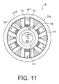
FIG. 11 shows theend plate 26a provided to therotor 14, viewed from the outside in the axial direction.FIG. 12 shows an example including a different number of coolant discharge outlets from that inFIG. 10 .FIG. 13 is a cross sectional view along the line C-C inFIG. 11 .FIG. 14 is a cross sectional view along the line D-D inFIG. 11 . In the description below, a side closer to therotor core 24 is referred to as an "inside in the axial direction", and a side farther from therotor core 24 is referred to as an "outside in the axial direction", which is similarly applied throughout the specification and claims of this application. - As shown in
FIG. 1 , therotor 14 has theshaft 25 rotatably supported on the respective two end sides thereof, therotor core 24 fitted and fixed around theshaft 25 by means of caulking, thermal insertion, pressure insertion, or the like, and theend plates rotor core 24 in the axial direction. The induction coils 28n, 28s and thecommon coils rotor core 24, as described above. Theend plates rotor core 24 in the axial direction, thereby constituting the end portions in the axial direction of therotor 14 that defines a cylindrical shape excluding theshaft 25. - A
coolant path 89 is formed in theshaft 25 so as to extend in the axial direction. Cooling oil, or an example of liquid coolant, is supplied for circulation into thecoolant path 89 via an oil pump, an oil cooler, or the like. - An inside
concave portion 90 is formed in the inside of eachend plate coils rotor core 24. Further, an outsideconcave portion 91 including a substantially conical space is formed outside eachend plate end plate rotor core 24 in the outer circumferential end portion and the inner circumferential end portion of theend plates - For example, the inside end portion in the axial direction of the outer circumferential portion of each
end plate salient poles 42. In this case, a concave portion may be formed on the inside end portion in the axial direction of the outer circumferential portion of eachend plate connection pin 86 that projects in the axial direction beyond therotor core 24. - The
end plates rotor core 24 or the like, or sandwich therotor core 24 or the like from the respective two sides of therotor core 24 in the axial direction. Alternatively, theend plate rotor core 24 outward in the axial direction. - In each
end plate concave portion 90 and the outsideconcave portion 91 are separated from each other by anend wall portion 92 that is substantially opposed in the axial direction. Theend wall portion 92 is formed inclined so as to be positioned more outward in the axial direction as it goes outward in the radial direction, as described above. The outer surface of theend wall portion 92 constitutes the end surface of therotor 14 in the axial direction. - In the
rotor 14 in this embodiment, diode devices 41 (an electronic device) integrally including a pair of first andsecond diodes end plates end plate 26a. In more detail, a plurality of mountingslots 94 each having an abutment wall portion on the outer circumferential portion are formed on the outer circumferential surface of theend wall portion 92 of theend plate 26a at an interval in the circumferential direction so as to extend radially. Anopening 95 for electric connection between therespective coils diode device 41 is formed on the inner circumferential side of each mountingslot 94, so that the insideconcave portion 90 and the outsideconcave portion 91 are communicated with each other via theopening 95. - The
diode device 41 is fitted and placed in the mountingslot 94 and fixed by a screw or the like, for example, while abutting on the abutment wall portion 93 in a position outside in the radial direction. In this embodiment, six mountingslots 94 are formed, and adiode device 41 is placed in each mountingslot 94. As thediode device 41 is provided contacting the abutment wall portion 93 in a position outside in the radial direction, it is possible to reliably hold or support thediode device 41 against a centrifugal force that acts on while therotor 14 is rotating - Although it is described in this embodiment that all
diode devices 41 are mounted on oneend plate 26a, this is not limiting, and thediode devices 41 may be shared to also be mounted on theother end plate 26b. Specifically, three out of the sixdiode devices 41 shown inFIG. 11 may be mounted on theother end plate 26b. - The first and
second diodes first diode 38 may be mounted on theend plate 26a, and thesecond diode 40 may be mounted on theother end plate 26b. - The first and
second diodes end wall portion 92 of theend plate 26a. In this case, theopening 95 on theend plate 26a is unnecessary, which can produce an advantage of simplifying work on the end plate. In this case, it is preferable that theend wall portion 92 of theend plate 26a be formed inclined inward in the axial direction, so that the cooling oil can flow more readily on the inner surface of theend wall portion 92. Further, in this case, an advantage can be produced that acover member 100 to be described later, provided to prevent the cooling oil from changing into mist due to wind pressure caused by the rotor rotating, is unnecessary. - Still further, when the end plate is a simple annular plate provided apart from the
rotor core 24 outward in the axial direction, a diode device or a rectifier may be mounted on the surface of the plate opposed to the rotor core. - As shown in
FIG. 11 , eachdiode device 41 has three terminals, in which two outside terminals of the three are connected to the respective end portions of theinduction coils common coil 30n (seeFIG. 5 ). The respective end portions of theinduction coils common coil 30n connected to thediode device 41 extend from the inner circumferential side of thecommon coil 30n (30s) to the outside in the axial direction, and project via theopening 95 of theend plate 26a to be connected to the terminal of thediode device 41 by means of welding, caulking, or the like. Note thatFIG. 13 shows a situation in which one terminal is connected to a coil end portion. - Referring to
FIGs 11 andFIG. 13 , a plurality ofcoolant discharge outlets 98 are formed penetrating in theend wall portion 92 of theend plate 26a. Thecoolant discharge outlet 98 is formed between thediode devices 41 in the circumferential direction at a position closer to the inner radial side. As thecoolant discharge outlet 98 is positioned as such, the cooling oil discharged from thecoolant discharge outlet 98 spreads into a substantially fan shape, as indicated by the broken line in the drawing, due to a centrifugal force by the rotatingrotor 14 to flow outward in the radial direction, but is prevented from directly touching thediode device 41. This can prevent deficiencies, such as abrasion or the like, caused by the cooling oil flowing outward in the radial direction at a high speed due to a centrifugal force and touching or bumping into thediode device 41. - Note that although an example is described, referring to
FIG. 11 , in which onecoolant discharge outlet 98 is formed between thediode devices 41, this is not limiting. For example, as shown inFIG. 12 , twocoolant discharge outlets 98 may be formed between thediode devices 41. When a plurality ofcoolant discharge outlets 98 are formed between thediode devices 41, as described above, it is possible to increase the amount of cooling oil to be supplied to thereby enlarge the area on theend wall portion 92 where the cooling oil flows, and resultantly, to improve cooling performance of indirectly cooling thediode device 41 via theend plate 26a by the cooling oil. - As shown in
FIG. 14 , a plurality of coolant supply paths (a first coolant supply path) 96 are formed in theshaft 25, arranged in the circumferential direction at an interval so as to extend in the radial direction. Thecoolant supply path 96 is a path for supplying the cooling oil flowing in thecoolant path 89 in the shaft to the outside of the shaft. The outside end portion of thecoolant supply path 96 is spot faced to be wider on the surface of theshaft 25, which makes it easier to position relative to another coolant supply path (a second coolant supply path) formed on theend plate 26a. - Note that although it is described here that the second coolant supply path is formed in the end plate, this is not limiting, and the space or the like left between the end plate and the rotor core, for example, may constitute the second coolant supply path.
- Another
coolant supply path 97 communicating with thecoolant supply path 96 of theshaft 25 is formed in theend plate 26a so as to penetrate. Thecoolant supply path 97 is connected to thecoolant discharge outlet 98 that is open on theend wall portion 92. In other words, the end portion itself of thecoolant supply path 97 that is open on theend wall portion 92 makes thecoolant discharge outlet 98. - As shown in
FIGs 13 and14 , thecover member 100 may be provided to theend plate 26a so as to cover at least the outer circumferential portion of the outsideconcave portion 91. Thecover member 100 can be preferably made using an annular plate. Acoolant discharge outlet 102 is formed in the outer circumferential portion of thecover member 100. Thecoolant discharge outlet 102 has a function for regulating the amount of cooling oil pooled in acoolant sump 103, or a spatial area defined between thecover member 100 and theend plate 26a and positioned outside in the radial direction. - In more detail, when the
coolant discharge outlet 102 is formed at a position much closer to the outer circumference, a smaller amount of oil is pooled in thecoolant sump 103, while when thecoolant discharge outlet 102 is formed at a position much closer to the inter circumference, a larger amount of oil is pooled in thecoolant sump 103. Therefore, the formation position, size, and shape of thecoolant discharge outlet 102 may be desirably set such that a desired amount of cooling oil is discharged from thecoolant discharge outlet 98 and flows outward in the radial direction due to a centrifugal force so that preferable cooling performance can be obtained. - Further, the
cover member 100 also has a function for preventing the cooling oil discharged from thecoolant opening 95 from changing into mist. In more detail, as thecoolant discharge outlet 98 is formed on theend plate 26a at a position farther from the end surface thereof in the axial direction inward in the axial direction (that is, on the bottom portion of the outsideconcave portion 91 or nearby), and thecover member 100 is provided substantially covering the outsideconcave portion 91 of theend plate 26a, it is possible to prevent thecoolant discharge outlet 98 from being exposed to the surrounding air due to high speed rotation of therotor 14. As a result, it is possible to have the cooling oil flow reliably in a liquid state outward in the radial direction along the surface of theend wall portion 92 of theend plate 26a. - In the rotating
electric machine 10 having therotor 14 employing the above described cooling structure that uses oil supplied from the shaft, cooling oil is supplied to thecoolant path 89 in theshaft 25 positioned inside in the radial direction relative to thediode device 41 mounted on therotor 14, and further to the outside of the shaft via thecoolant supply paths coolant discharge outlet 98. The cooling oil discharged from thecoolant discharge outlet 98 flows outward in the radial direction, while spreading in the circumferential direction along a substantially fan-shaped surface area on theend wall portion 92 positioned between thediode devices 41. - Meanwhile, the
diode device 41 including the first andsecond diodes induction coils diode device 41 to theend plate 26a, and then removed by the cooling oil flowing on the outer surface of theend wall portion 92, as described above. That is, thediode device 41 is indirectly cooled by the cooling oil via theend plate 26a. - In the
end plate 26a in this embodiment, the outer surface of theend wall portion 92 continuing to thecoolant discharge outlet 98 is inclined relative to the radial direction so as to be positioned more outward in the axial direction as it goes outward in the radial direction. With the above, when the cooling oil discharged from thecoolant discharge outlet 98 flows on the outer surface of theend wall portion 92, a pressing force for pressing onto the outer surface will act on the cooling oil as a divided force of the centrifugal force caused by the rotating rotor. With the pressing force acting on it, the cooling oil can remain in a liquid state, without being changed into mist, while flowing outward in the radial direction on the outer surface of theend wall portion 92. As a result, it is possible to obtain sufficient cooling performance for thediode device 41. - The cooling oil having flown outward in the radial direction on the outer surface of the
end wall portion 92 is temporarily pooled in thecoolant sump 103. The cooling oil removes heat from theend plate 26a, even while being pooled, to thereby indirectly cool thediode device 41. Thereafter, the cooling oil overflown from thecoolant sump 103 is discharged from thecoolant discharge outlet 102 to the outside of therotor 14. Then, the cooling oil is discharged from the bottom of a case for accommodating the rotatingelectric machine 10, and after passing through an oil cooler to discharge heat and lower the temperature, is supplied for circulation to thecoolant path 89 in theshaft 25 by an action of an oil pump or the like. - As described above, according to the rotating
electric machine 10 in this embodiment, cooling oil from thecoolant path 89 of theshaft 25 positioned inside in the radial direction relative to thediode device 41 mounted on theend plate 26a is discharged from thecoolant discharge outlet 98 of theend plate 26a via thecoolant supply paths rotating rotor 14, and flows outward in the radial direction on the outer surface of theend wall portion 92 of theend plate 26a to be supplied to around thediode device 41. With the above, it is possible to sufficiently cool thediode device 41 that generates heat upon application of electricity, via theend plate 26a having preferable heat conductivity. - As this embodiment has such an arrangement that cooling oil is supplied to between the
diode devices 41 in the circumferential direction, thediode device 41 can be mounted at a position closer to the inner circumference, compared to an arrangement in which thecoolant discharge outlet 98 is formed on the inner circumference side of thediode device 41. Therefore, it is possible to prevent the centrifugal force that acts on the diode device 41 (that is, the first andsecond diodes 38, 40) due to therotating rotor 14, which makes it possible to reduce the weight of a support portion (corresponding to the abutment wall portion 93 in this embodiment), which abuts on the diode at a position outside in the radial direction, against a centrifugal force and to prevent failure of an electronic device. - In the following, an example including a different structure for cooling the diode device mounted on the rotor by cooling oil is described referring to
FIGs 15 to 19 . A structure different from that in the above-described embodiment is mainly described here, and structures identical to those in the above are given the same reference numerals and not described again. -
FIG. 15 shows another example in which a coolant discharge outlet is formed on the shaft, and is a drawing corresponding toFIG. 14 . In the example shown inFIG. 15 , the position where thecoolant supply path 96 is formed on theshaft 25 is different. That is, thecoolant discharge outlet 98, or an end portion of thecoolant supply path 96, is formed open on the surface of theshaft 25. With the above, it is possible to supply the cooling oil discharged from thecoolant supply path 96 directly onto the outer surface of theend wall portion 92 of theend plate 26a (that is, not via the coolant supply path in the end plate), which can produce an advantage of omitting labor and working cost for providing a coolant supply path and a coolant discharge outlet in the end plate. In this case, it is preferable to have thecoolant discharge outlet 98 substantially flush with the bottom portion of the outsideconcave portion 91 of theend plate 26a so that the cooling oil discharged from thecoolant discharge outlet 98 on theshaft 25 flows smoothly without splashing. -
FIG. 16 shows still another example in which a coolant discharge outlet is formed outside the rotor, and is a drawing corresponding toFIG. 14 . In this example, cooling oil is supplied from the outside of therotor 14 into the outsideconcave portion 91 of theend plate 26a. Specifically, acoolant supply pipe 99 extending from a non-rotating portion, such as a case (not shown) or the like, for accommodating the rotatingelectric machine 10 is provided near theend plate 26a of therotor 14, and the cooling oil is poured into the outsideconcave portion 91 of theend plate 26a from thecoolant discharge outlet 98 on the tip end portion of thecoolant supply pipe 99. In this case, it is preferable for the position where the cooling oil is supplied to theend plate 26a to be closer to the inner circumference than thediode device 41 mounted on theend plate 26a. With the above, it is possible to have the cooling oil supplied from the outside of the rotor to theend plate 26a to flow outward in the radial direction due to an action of a centrifugal force, whereby thediode device 41 is preferably cooled via theend plate 26a. Further, in this case, as it is unnecessary to supply the cooling oil from theshaft 25, an advantage can be produced that labor and working cost for forming a coolant channel, a coolant supply path, a coolant discharge outlet, and the like, in theshaft 25 can be omitted. -
FIG. 17 shows still another example of a structure in which a coolant path is formed in theend plate 26a, and is a drawing corresponding toFIG. 14 .FIG. 18 is a cross sectional view along the line E-E inFIG. 17 . Note that no cover member is provided on the end surface of theend plate 26a here. - In this example, a
coolant path 104 is formed extending in theend wall portion 92 of theend plate 26a. The inside end portion of thecoolant path 104 in the radial direction communicates with thecoolant supply path 96 formed in theshaft 25, while the outside end portion of thecoolant path 104 in the radial direction is open on the outer circumferential surface of theend plate 26a, constituting thecoolant discharge outlet 98. Therefore, thecoolant path 104 formed in theend plate 26a is positioned between thediode device 41 mounted on the outer surface of theend wall portion 92 and thecoils end wall portion 92 in the axial direction. - With the
coolant path 104 formed between thediode device 41 and thecoils diode device 41 and thecoils coolant path 89 and thecoolant supply path 96 of theshaft 25 and flowing in thecoolant path 104. - In more detail, it is often a case that the
coils diode device 41, and cooling capability of the cooling oil passing in thecooling path 104 may turn out to be excessive for thediode device 41. In such a case, with an arrangement in which thecoils coils - In this example, as shown in
FIG. 18 , aheat discharge fin 106 may be provided at a position on the inside wall surface of thecoolant path 104, the position corresponding to thediode device 41. With the above, it is possible to efficiently discharge the heat transmitted from thediode device 41 to theend wall portion 92, from theheat discharge fin 106 to the cooling oil in thecoolant path 104. This improves cooling performance with respect to thediode device 41. - Note that the
coolant path 104 may be positioned displaced in the circumferential direction relative to thediode device 41 when viewed from the axial direction, as long as thecoolant path 104 is positioned between thediode device 41 and thecoils -
FIG. 19 shows an example in which an electronic device is covered by mold resin, and coolant is supplied to the top of the mold resin, and is a drawing corresponding toFIG. 13 . Although thecover member 100 is not shown here either, thecover member 100 having a function such as is described referring toFIG. 14 may be provided. - In this example, the
diode device 41 mounted on theend plate 26a is covered by amold resin portion 108. Themold resin portion 108 is also filled around a connection portion of the terminal of thediode device 41 and the end portions of thecoils - The
mold resin portion 108 does not necessarily cover the entire outer surface of theend wall portion 92 as long as it is formed so as to prevent exposure of at least thediode device 41. For example, themold resin portion 108 may have so small a width that it covers the mountingslot 94 for mounting the diode device 41 (seeFIG. 11 ). - In the above described manner, even when the
coolant discharge outlet 98 is formed on theshaft 25 positioned inside in the radial direction relative to thediode device 41, it is possible to sufficiently cool thediode device 41 as the cooling oil discharged from thecoolant discharge outlet 98 flows on themold resin portion 108 covering thediode device 41. Moreover, it is possible to prevent deficiencies, such as abrasion or deterioration, caused by the cooling oil flowing outward in the radial direction at a high speed due to a centrifugal force and touching or bumping into thediode device 41 as the cooling oil does not directly touch thediode device 41. Further, in also this example, similar to the example shown inFIG. 11 , as thecoolant discharge outlet 98 is formed between thediode devices 41 in the circumferential direction to supply cooling oil, it is possible to indirectly cool thediode device 41 via theend wall portion 92. This can be expected to further improve cooling performance. - Although an embodiment of the present invention and modified examples thereof are described in the above, a rotating electric machine according to the present invention is not limited to the above described structures, and various modifications and improvements are possible.
- For example, the coil end portions of the
coils rotor core 24 may be covered by mold resin, and the mold resin may be substantially filled in the insideconcave portion 90 of theend plate 26a when theend plate 26a is assembled to therotor core 24. With the above, heat transmission from thecoils end plate 26a via the mold resin having higher thermal conductive rate than air is accelerated, which can improve cooling performance with respect to thecoils concave portion 90 via theopening 95 of theend wall portion 92 at the same time as formation of themold resin portion 108 shown inFIG. 19 makes it possible to reduce the number of molding steps and thus the number of manufacturing steps and costs. - Although a structure is described in the above embodiment in which the
diode device 41 is mounted on theend plate 26a and is cooled by the cooling oil supplied from thecoolant path 89 of theshaft 25, this is not limiting. For example, a structure may be applicable in which a mold resin portion for covering thecoils rotor core 24 is provided, a diode device is fixed on or in the mold resin portion, and liquid coolant supplied from the shaft or a non-rotating portion is supplied toward the mold resin portion, to thereby cool the diode device and, if necessary, cool the coils. - Although the
diode device 41 is mounted on theend plate 26a by a screw or the like in the above described embodiment, a diode device or a rectifier may be directly mounted on at least either the shaft or the rotor core, or on a plate member fixed to the shaft at an interval in the axial direction relative to the rotor core or the like. - Although it is described in the above described embodiment that a diode device or a rectifier that is a separate member is mounted on the end plate provided to the end portion of the rotor core by a screw or the like, this is not limiting. For example, a diode device made of a semiconductor device and integrally formed with or built in the end plate may be used.
- 10 rotating electric machine, 12 stator, 14, 14a, 14b rotor, 16 stator core, 18 teeth, 20u, 20v, 20w stator coil, 22 slot, 24 rotor core, 25 shaft, 26a, 26b end plate, 28n N-pole induction coil, 28s S-pole induction coil, 30n N-pole common coil, 30s S-pole common coil, 32n N-pole formed salient pole, 32s S-pole formed salient pole, 33 rotor yoke, 34 slot, 36 common coil pair, 38 first diode, 40 second diode, 41 diode device, 42 auxiliary salient pole, 44 brim portion, 46 outside convex portion, 48 shaft-side root portion, 50 shaft-side tip end portion, 52 maximum width portion, 54 first core element, 56 second core element, 62 rotor-side root portion, 64 rotor-side tip end portion, 70 inside concave portion, 72 wider portion, 74 half round portion, 78 diagonally projecting portion, 80 circumferential projecting portion, 85 pin slot, 86 connection pin, 87 pin insertion portion, 88 backlash reducing pin, 89 coolant channel, 90 inside concave portion, 91 outside concave portion, 92 end wall portion, 93 abutment wall portion, 94 mounting slot, 95 opening, 96, 97 coolant supply path, 98 coolant discharge outlet, 100 cover member, 102 coolant discharge slot, 103 coolant sump, 104 coolant path, 106 heat discharge fin.
Claims (10)
- A rotating electric machine, comprising:a stator for generating a rotating magnetic field;a rotatable rotor placed opposed to the stator;an electronic device connected to a coil wound around the rotor, for rotating together with the rotor; anda cooling structure for cooling the electronic device with liquid coolant supplied from inside in a radial direction relative to the electronic device.
- The rotating electric machine according to claim 1, wherein the cooling structure has a coolant path formed in a shaft for rotatably supporting the rotor and a coolant supply path for supplying the liquid coolant flowing in the coolant path to outside of the shaft.
- The rotating electric machine according to claim 2, wherein
the electronic device includes a plurality of electronic devices placed on an end surface of the rotor in an axial direction at intervals in a circumferential direction, and
an end portion of the coolant supply path is open between the electronic devices in the circumferential direction. - The rotating electric machine according to claim 3, wherein
the electronic device is mounted on an end plate that constitutes the end surface of the rotor in the axial direction, and
the coolant supply path includes a first coolant supply path formed in the shaft and a second coolant supply path formed in the end plate, in which an end portion of the second coolant supply path is open on a surface of the end plate. - The rotating electric machine according to claim 2, wherein
the electronic device is mounted on an end plate that constitutes an end surface of the rotor in an axial direction, and
the coolant supply path is formed in the shaft to supply the liquid coolant from the coolant path to outside of the shaft, in which an end portion of the coolant supply path is open on a surface of the end plate. - The rotating electric machine according to claim 4 or 5, wherein the surface of the end plate onto which the liquid coolant is supplied from the coolant supply path is inclined outward in the axial direction relative to the radial direction.
- The rotating electric machine according to claim 2, wherein
the electronic device is mounted on an end plate that constitutes an end surface of the rotor in an axial direction, and
the coolant supply path continues to an outer circumferential surface of the end plate at a position between the electronic device and the coil via a path formed in the end plate. - The rotating electric machine according to claim 7, wherein a heat discharge fin is formed on an inside wall surface of the path on a back surface side of the electronic device.
- The rotating electric machine according to claim 2, wherein
the electronic device is mounted on an end plate that constitutes an end surface of the rotor in an axial direction,
an opening on an end portion of the coolant supply path is positioned apart from an end surface of the end plate in the axial direction inward in the axial direction, and
a cover member for covering at least an outer circumferential portion is provided on the end surface of the end plate in the axial direction. - The rotating electric machine according to claim 9, wherein a coolant discharge slot for regulating an amount of coolant pooled in a coolant sump for pooling the liquid coolant which is discharged from a coolant discharge outlet and flows outward in the radial direction is formed on an outer circumferential portion of the cover member.
Applications Claiming Priority (1)
| Application Number | Priority Date | Filing Date | Title |
|---|---|---|---|
| PCT/JP2011/076805 WO2013076791A1 (en) | 2011-11-21 | 2011-11-21 | Rotating electric machine |
Publications (2)
| Publication Number | Publication Date |
|---|---|
| EP2784918A1 true EP2784918A1 (en) | 2014-10-01 |
| EP2784918A4 EP2784918A4 (en) | 2016-03-16 |
Family
ID=48469273
Family Applications (1)
| Application Number | Title | Priority Date | Filing Date |
|---|---|---|---|
| EP11876143.6A Withdrawn EP2784918A4 (en) | 2011-11-21 | 2011-11-21 | ROTATING ELECTRIC MACHINE |
Country Status (5)
| Country | Link |
|---|---|
| US (1) | US9484789B2 (en) |
| EP (1) | EP2784918A4 (en) |
| JP (1) | JP5641154B2 (en) |
| CN (1) | CN104011982A (en) |
| WO (1) | WO2013076791A1 (en) |
Cited By (4)
| Publication number | Priority date | Publication date | Assignee | Title |
|---|---|---|---|---|
| WO2015034544A3 (en) * | 2013-09-06 | 2015-09-24 | Ge Aviation Systems Llc | Rotor assembly for an electric machine |
| EP3675332A1 (en) * | 2018-12-27 | 2020-07-01 | Ge Aviation Systems Llc, Inc. | Rotor for an electric machine |
| DE102015219708B4 (en) | 2014-10-14 | 2021-08-26 | Suzuki Motor Corporation | engine |
| DE102023124375A1 (en) | 2023-09-11 | 2025-03-13 | Bayerische Motoren Werke Aktiengesellschaft | Salient pole rotor and current-excited synchronous machine for a motor vehicle |
Families Citing this family (16)
| Publication number | Priority date | Publication date | Assignee | Title |
|---|---|---|---|---|
| JP6485102B2 (en) * | 2015-02-20 | 2019-03-20 | スズキ株式会社 | Rotating electric machine |
| GB2549086B (en) * | 2016-03-30 | 2022-09-07 | Advanced Electric Machines Group Ltd | Electrical sub-assembly |
| US10216682B2 (en) * | 2016-06-15 | 2019-02-26 | Epro Gmbh | Configuration distribution |
| US11177708B2 (en) | 2017-01-13 | 2021-11-16 | Ge Aviation Systems Llc | Method for manufacturing an integrated stator and housing for an electrical machine |
| US10523096B2 (en) | 2017-01-13 | 2019-12-31 | Ge Aviation Systems Llc | Method for manufacturing a stator assembly of an electrical machine |
| US10424989B2 (en) | 2017-01-13 | 2019-09-24 | General Electric Company | Methods for manufacturing a housing for an electrical machine |
| US10792750B2 (en) | 2017-01-13 | 2020-10-06 | Ge Aviation Systems Llc | Methods for manufacturing a rotor assembly for an electrical machine |
| US10476358B2 (en) | 2017-01-13 | 2019-11-12 | General Electric Company | Methods for manufacturing an electric machine |
| US10826363B2 (en) | 2018-05-10 | 2020-11-03 | Ge Aviation Systems Llc | Additively manufactured assemblies for electrical machines |
| US11038389B2 (en) * | 2018-08-24 | 2021-06-15 | Hamilton Sundstrand Corporation | Rotor end plate |
| CN114123569A (en) * | 2021-12-01 | 2022-03-01 | 湖南龙德晟机电科技有限公司 | Efficient and energy-saving small motor and wiring method |
| DE102021213736A1 (en) * | 2021-12-02 | 2023-06-07 | Valeo Eautomotive Germany Gmbh | Compact rotor for an electrical machine with an inductive transmitter, as well as an electrical machine and vehicle |
| JP2025085859A (en) * | 2022-04-28 | 2025-06-06 | 株式会社アイシン | Wound-field type rotating electric machine |
| DE102023200309A1 (en) * | 2023-01-17 | 2024-07-18 | Mahle International Gmbh | Rotor for a separately excited synchronous machine |
| DE102024112875A1 (en) * | 2024-05-08 | 2025-11-13 | Mahle International Gmbh | Synchronous machine |
| US20260122760A1 (en) | 2024-10-29 | 2026-04-30 | GM Global Technology Operations LLC | Liquid cooled pcb for inductive power transfer & inverter electronics |
Family Cites Families (19)
| Publication number | Priority date | Publication date | Assignee | Title |
|---|---|---|---|---|
| CA587388A (en) * | 1957-03-12 | 1959-11-17 | Westinghouse Electric Corporation | Alternating current dynamoelectric machine |
| US3896320A (en) * | 1971-10-19 | 1975-07-22 | United Aircraft Corp | High speed electric generator |
| JPS58148649A (en) * | 1982-02-24 | 1983-09-03 | Hitachi Ltd | brushless alternator |
| JPS58186776A (en) | 1982-04-26 | 1983-10-31 | Fuji Xerox Co Ltd | Cleaning device of electronic copying machine |
| JPS58186776U (en) * | 1982-06-07 | 1983-12-12 | 三菱電機株式会社 | liquid cooled rotating electric machine |
| US4628219A (en) * | 1985-09-13 | 1986-12-09 | Sundstrand Corporation | Rectifier assembly for mounting in a rotor |
| US4959707A (en) * | 1989-04-14 | 1990-09-25 | Sundstrand Corporation | Rotating rectifier assembly |
| JPH0529275A (en) | 1991-07-23 | 1993-02-05 | Kokusai Electric Co Ltd | Plasma etching method and apparatus |
| JP2564130Y2 (en) | 1991-09-26 | 1998-03-04 | 国産電機株式会社 | Brushless generator with built-in exciter |
| US5319272A (en) * | 1992-07-14 | 1994-06-07 | Eemco/Datron, Inc. | Miniature rotating rectifier assembly |
| JPH0946990A (en) * | 1995-08-02 | 1997-02-14 | Meidensha Corp | Excitation structure of brushless generator |
| JP3306744B2 (en) | 1996-04-30 | 2002-07-24 | デンヨー株式会社 | Balance adjustment mechanism for rotor of 4-pole salient-pole brushless AC generator |
| EP0989658A1 (en) | 1998-09-28 | 2000-03-29 | The Swatch Group Management Services AG | Liquid-cooled aynchronous electric machine |
| JP3877899B2 (en) * | 1999-03-09 | 2007-02-07 | 三菱電機株式会社 | AC generator for vehicles |
| JP3797225B2 (en) | 2001-05-01 | 2006-07-12 | 株式会社デンソー | AC generator for vehicles |
| JP2005006429A (en) * | 2003-06-12 | 2005-01-06 | Toyota Motor Corp | Rotor structure in rotating electrical machines |
| JP2009148047A (en) | 2007-12-12 | 2009-07-02 | Sugai Sogyo:Kk | Motor cooling system |
| JP4483948B2 (en) * | 2008-01-17 | 2010-06-16 | トヨタ自動車株式会社 | Rotating electric machine |
| JP5363913B2 (en) | 2009-08-18 | 2013-12-11 | 株式会社豊田中央研究所 | Rotating electric machine drive system |
-
2011
- 2011-11-21 JP JP2013545669A patent/JP5641154B2/en not_active Expired - Fee Related
- 2011-11-21 CN CN201180074973.4A patent/CN104011982A/en active Pending
- 2011-11-21 WO PCT/JP2011/076805 patent/WO2013076791A1/en not_active Ceased
- 2011-11-21 US US14/359,419 patent/US9484789B2/en not_active Expired - Fee Related
- 2011-11-21 EP EP11876143.6A patent/EP2784918A4/en not_active Withdrawn
Cited By (5)
| Publication number | Priority date | Publication date | Assignee | Title |
|---|---|---|---|---|
| WO2015034544A3 (en) * | 2013-09-06 | 2015-09-24 | Ge Aviation Systems Llc | Rotor assembly for an electric machine |
| DE102015219708B4 (en) | 2014-10-14 | 2021-08-26 | Suzuki Motor Corporation | engine |
| EP3675332A1 (en) * | 2018-12-27 | 2020-07-01 | Ge Aviation Systems Llc, Inc. | Rotor for an electric machine |
| US11025114B2 (en) | 2018-12-27 | 2021-06-01 | Ge Aviation Systems Llc | Rotor for an electric machine |
| DE102023124375A1 (en) | 2023-09-11 | 2025-03-13 | Bayerische Motoren Werke Aktiengesellschaft | Salient pole rotor and current-excited synchronous machine for a motor vehicle |
Also Published As
| Publication number | Publication date |
|---|---|
| JPWO2013076791A1 (en) | 2015-04-27 |
| WO2013076791A1 (en) | 2013-05-30 |
| US20150022035A1 (en) | 2015-01-22 |
| EP2784918A4 (en) | 2016-03-16 |
| US9484789B2 (en) | 2016-11-01 |
| JP5641154B2 (en) | 2014-12-17 |
| CN104011982A (en) | 2014-08-27 |
Similar Documents
| Publication | Publication Date | Title |
|---|---|---|
| US9484789B2 (en) | Rotating electric machine | |
| JP5641156B2 (en) | Rotating electric machine rotor and rotating electric machine equipped with the same | |
| JP5641155B2 (en) | Rotating electric machine rotor and rotating electric machine equipped with the same | |
| US10707726B2 (en) | Cooling structure for dynamo-electric machine | |
| US9419499B2 (en) | Rotating electric machine having a cooling device and cooling liquid collection tanks | |
| EP2546962A1 (en) | Vehicle ac generator | |
| JP4389918B2 (en) | Rotating electric machine and AC generator | |
| JP6544151B2 (en) | Electric rotating machine | |
| US10038353B2 (en) | Dual-rotor electric rotating machine | |
| JP2012010565A (en) | Permanent magnet rotary electric machine | |
| JP5483094B2 (en) | Rotating electrical machine rotor | |
| US10797543B2 (en) | Rotating electric machine | |
| JP5955437B1 (en) | Rotating electric machine | |
| JP5724843B2 (en) | Rotating electric machine | |
| JP2018046690A (en) | Rotary electric machine | |
| JP2016129447A (en) | Rotary electric machine | |
| JP2019154197A (en) | Rotary electric machine | |
| JP2010166787A (en) | Rotating electrical machine | |
| JP6645352B2 (en) | Rotating electric machine | |
| JPWO2014188505A1 (en) | Rotating electric machine | |
| JP2013110800A (en) | Ac power generator for vehicle | |
| HK1146157A1 (en) | An ac electric machine | |
| HK1146157B (en) | An ac electric machine |
Legal Events
| Date | Code | Title | Description |
|---|---|---|---|
| PUAI | Public reference made under article 153(3) epc to a published international application that has entered the european phase |
Free format text: ORIGINAL CODE: 0009012 |
|
| 17P | Request for examination filed |
Effective date: 20140521 |
|
| AK | Designated contracting states |
Kind code of ref document: A1 Designated state(s): AL AT BE BG CH CY CZ DE DK EE ES FI FR GB GR HR HU IE IS IT LI LT LU LV MC MK MT NL NO PL PT RO RS SE SI SK SM TR |
|
| DAX | Request for extension of the european patent (deleted) | ||
| RA4 | Supplementary search report drawn up and despatched (corrected) |
Effective date: 20160217 |
|
| RIC1 | Information provided on ipc code assigned before grant |
Ipc: H02K 1/28 20060101ALN20160210BHEP Ipc: H02K 19/12 20060101ALI20160210BHEP Ipc: H02K 1/24 20060101ALN20160210BHEP Ipc: H02K 11/042 20160101ALI20160210BHEP Ipc: H02K 1/32 20060101ALI20160210BHEP Ipc: H02K 9/19 20060101AFI20160210BHEP Ipc: H02K 17/26 20060101ALN20160210BHEP |
|
| GRAP | Despatch of communication of intention to grant a patent |
Free format text: ORIGINAL CODE: EPIDOSNIGR1 |
|
| RIC1 | Information provided on ipc code assigned before grant |
Ipc: H02K 1/32 20060101ALI20160610BHEP Ipc: H02K 1/24 20060101ALN20160610BHEP Ipc: H02K 1/28 20060101ALN20160610BHEP Ipc: H02K 9/19 20060101AFI20160610BHEP Ipc: H02K 17/26 20060101ALN20160610BHEP Ipc: H02K 19/12 20060101ALI20160610BHEP Ipc: H02K 11/042 20160101ALI20160610BHEP |
|
| INTG | Intention to grant announced |
Effective date: 20160714 |
|
| STAA | Information on the status of an ep patent application or granted ep patent |
Free format text: STATUS: GRANT OF PATENT IS INTENDED |
|
| STAA | Information on the status of an ep patent application or granted ep patent |
Free format text: STATUS: THE APPLICATION IS DEEMED TO BE WITHDRAWN |
|
| 18D | Application deemed to be withdrawn |
Effective date: 20161125 |