EP2784769B1 - Scan-type light irradiation device for image display - Google Patents
Scan-type light irradiation device for image display Download PDFInfo
- Publication number
- EP2784769B1 EP2784769B1 EP14000573.7A EP14000573A EP2784769B1 EP 2784769 B1 EP2784769 B1 EP 2784769B1 EP 14000573 A EP14000573 A EP 14000573A EP 2784769 B1 EP2784769 B1 EP 2784769B1
- Authority
- EP
- European Patent Office
- Prior art keywords
- vertical
- supplied
- signal
- image
- horizontal
- Prior art date
- Legal status (The legal status is an assumption and is not a legal conclusion. Google has not performed a legal analysis and makes no representation as to the accuracy of the status listed.)
- Active
Links
Images




Classifications
-
- G—PHYSICS
- G09—EDUCATION; CRYPTOGRAPHY; DISPLAY; ADVERTISING; SEALS
- G09G—ARRANGEMENTS OR CIRCUITS FOR CONTROL OF INDICATING DEVICES USING STATIC MEANS TO PRESENT VARIABLE INFORMATION
- G09G5/00—Control arrangements or circuits for visual indicators common to cathode-ray tube indicators and other visual indicators
- G09G5/10—Intensity circuits
-
- G—PHYSICS
- G09—EDUCATION; CRYPTOGRAPHY; DISPLAY; ADVERTISING; SEALS
- G09G—ARRANGEMENTS OR CIRCUITS FOR CONTROL OF INDICATING DEVICES USING STATIC MEANS TO PRESENT VARIABLE INFORMATION
- G09G3/00—Control arrangements or circuits, of interest only in connection with visual indicators other than cathode-ray tubes
- G09G3/02—Control arrangements or circuits, of interest only in connection with visual indicators other than cathode-ray tubes by tracing or scanning a light beam on a screen
- G09G3/025—Control arrangements or circuits, of interest only in connection with visual indicators other than cathode-ray tubes by tracing or scanning a light beam on a screen with scanning or deflecting the beams in two directions or dimensions
-
- G—PHYSICS
- G09—EDUCATION; CRYPTOGRAPHY; DISPLAY; ADVERTISING; SEALS
- G09G—ARRANGEMENTS OR CIRCUITS FOR CONTROL OF INDICATING DEVICES USING STATIC MEANS TO PRESENT VARIABLE INFORMATION
- G09G2310/00—Command of the display device
- G09G2310/02—Addressing, scanning or driving the display screen or processing steps related thereto
- G09G2310/0264—Details of driving circuits
- G09G2310/0283—Arrangement of drivers for different directions of scanning
-
- G—PHYSICS
- G09—EDUCATION; CRYPTOGRAPHY; DISPLAY; ADVERTISING; SEALS
- G09G—ARRANGEMENTS OR CIRCUITS FOR CONTROL OF INDICATING DEVICES USING STATIC MEANS TO PRESENT VARIABLE INFORMATION
- G09G2310/00—Command of the display device
- G09G2310/02—Addressing, scanning or driving the display screen or processing steps related thereto
- G09G2310/0264—Details of driving circuits
- G09G2310/0291—Details of output amplifiers or buffers arranged for use in a driving circuit
-
- G—PHYSICS
- G09—EDUCATION; CRYPTOGRAPHY; DISPLAY; ADVERTISING; SEALS
- G09G—ARRANGEMENTS OR CIRCUITS FOR CONTROL OF INDICATING DEVICES USING STATIC MEANS TO PRESENT VARIABLE INFORMATION
- G09G2310/00—Command of the display device
- G09G2310/06—Details of flat display driving waveforms
- G09G2310/067—Special waveforms for scanning, where no circuit details of the gate driver are given
-
- G—PHYSICS
- G09—EDUCATION; CRYPTOGRAPHY; DISPLAY; ADVERTISING; SEALS
- G09G—ARRANGEMENTS OR CIRCUITS FOR CONTROL OF INDICATING DEVICES USING STATIC MEANS TO PRESENT VARIABLE INFORMATION
- G09G2310/00—Command of the display device
- G09G2310/08—Details of timing specific for flat panels, other than clock recovery
-
- G—PHYSICS
- G09—EDUCATION; CRYPTOGRAPHY; DISPLAY; ADVERTISING; SEALS
- G09G—ARRANGEMENTS OR CIRCUITS FOR CONTROL OF INDICATING DEVICES USING STATIC MEANS TO PRESENT VARIABLE INFORMATION
- G09G2320/00—Control of display operating conditions
- G09G2320/02—Improving the quality of display appearance
- G09G2320/0233—Improving the luminance or brightness uniformity across the screen
-
- G—PHYSICS
- G09—EDUCATION; CRYPTOGRAPHY; DISPLAY; ADVERTISING; SEALS
- G09G—ARRANGEMENTS OR CIRCUITS FOR CONTROL OF INDICATING DEVICES USING STATIC MEANS TO PRESENT VARIABLE INFORMATION
- G09G2320/00—Control of display operating conditions
- G09G2320/02—Improving the quality of display appearance
- G09G2320/0247—Flicker reduction other than flicker reduction circuits used for single beam cathode-ray tubes
-
- G—PHYSICS
- G09—EDUCATION; CRYPTOGRAPHY; DISPLAY; ADVERTISING; SEALS
- G09G—ARRANGEMENTS OR CIRCUITS FOR CONTROL OF INDICATING DEVICES USING STATIC MEANS TO PRESENT VARIABLE INFORMATION
- G09G2320/00—Control of display operating conditions
- G09G2320/02—Improving the quality of display appearance
- G09G2320/0261—Improving the quality of display appearance in the context of movement of objects on the screen or movement of the observer relative to the screen
-
- G—PHYSICS
- G09—EDUCATION; CRYPTOGRAPHY; DISPLAY; ADVERTISING; SEALS
- G09G—ARRANGEMENTS OR CIRCUITS FOR CONTROL OF INDICATING DEVICES USING STATIC MEANS TO PRESENT VARIABLE INFORMATION
- G09G2320/00—Control of display operating conditions
- G09G2320/06—Adjustment of display parameters
- G09G2320/0626—Adjustment of display parameters for control of overall brightness
- G09G2320/064—Adjustment of display parameters for control of overall brightness by time modulation of the brightness of the illumination source
-
- G—PHYSICS
- G09—EDUCATION; CRYPTOGRAPHY; DISPLAY; ADVERTISING; SEALS
- G09G—ARRANGEMENTS OR CIRCUITS FOR CONTROL OF INDICATING DEVICES USING STATIC MEANS TO PRESENT VARIABLE INFORMATION
- G09G2320/00—Control of display operating conditions
- G09G2320/06—Adjustment of display parameters
- G09G2320/0626—Adjustment of display parameters for control of overall brightness
- G09G2320/0646—Modulation of illumination source brightness and image signal correlated to each other
-
- G—PHYSICS
- G09—EDUCATION; CRYPTOGRAPHY; DISPLAY; ADVERTISING; SEALS
- G09G—ARRANGEMENTS OR CIRCUITS FOR CONTROL OF INDICATING DEVICES USING STATIC MEANS TO PRESENT VARIABLE INFORMATION
- G09G2360/00—Aspects of the architecture of display systems
- G09G2360/14—Detecting light within display terminals, e.g. using a single or a plurality of photosensors
Definitions
- the present invention relates to a light irradiation device to spatially sequentially scan a spot or a beam of light and irradiate an object with the scanned light, and further to display an image.
- the light irradiation device generates intensity-modulated light, deflects the light while reciprocating it with a mirror or the like in one direction, and further, deflects the light while reciprocating it with the mirror in a direction vertical to the above direction, to irradiate an object with the light and two-dimensionally scan the object. It is considered that the light irradiation device is applicable to an image display device (projector) disclosed in e.g. Japanese Patent Application No. JP4639973B or a sensor to detect reflected light from an object irradiated with the light and measure the shape of the object or the distance from the object. Recently, downsizing and reduction of electric consumption are promoted regarding the light irradiation device, and applicability in various fields is expected. Related art is disclosed in US 2010/ 321750 A1 from which the pre-characterising part of claim 1 starts out, and in US 2011/001888 A1 . US 5680454 A discloses random variation of an image frame rate.
- the light-irradiated position in the object timewisely changes.
- displacement with respect to a predetermined reference position will be referred to as scan displacement.
- the viewpoint of a viewer who is watching a displayed image moves.
- the movement of the viewpoint occurs due to vibration of the image at a display unit of the image display device or intentional movement of the viewpoint by the viewer.
- the displacement with respect to the predetermined reference position of the viewer's viewpoint including these cases will be referred to as image displacement.
- an image influenced by the above-described scan displacement and the image displacement is formed. Accordingly, image distortion to be described later perceptionally occurs. For example, when of an image having uniform brightness is displayed, an image with uneven brightness is visually detected.
- the difference between the refresh rate determined based on the frame frequency (e.g. 30 Hz) of the image and the cycle of the above-described image displacement is small, since the above-described image distortion slowly moves on the display screen, it attracts the viewer's notice.
- the present invention has been made in view of the above-described problem, and has an object to provide a light irradiation device which prevents detection of distortion of displayed image.
- the present invention provides a light irradiation device as defined in the appended claims.
- Fig. 1 is a block diagram of a light irradiation device in a first example. First, the overall explanation will be made with reference to Fig. 1 , and thereafter, the characteristic features of the present example will be described.
- a video signal inputted from an input terminal 10 is a video signal for image display, and is supplied to a deflection device controller 11 and a light source controller 14.
- the deflection device controller 11 generates a synchronization signal in a direction vertical to a horizontal direction of a scanned and displayed image, based on the supplied video signal, and supplies the signal to a deflection device driver 12.
- the light source controller 14 generates a luminance control signal to control the luminance of a light source 16 to be described later, based on the luminance of the supplied video signal, and supplies the signal to a light source driver 15.
- the deflection device controller 11 generates e.g. a horizontal pulse signal with an H (Horizontal) timing generator 111 to indicate horizontal synchronization timing of the image based on the supplied video signal, and supplies the signal to an H waveform generator 112.
- the H waveform generator 112 generates e.g. a rectangular horizontal waveform signal for scanning in the horizontal direction based on the supplied horizontal pulse signal, and supplies the signal to the deflection device driver 12.
- the deflection device controller 11 generates e.g. a vertical pulse signal with a V (Vertical) timing generator 114 to indicate vertical synchronization timing of the image based on the supplied video signal, and supplies the signal to a V waveform generator 115.
- V Vertical
- the V waveform generator 115 generates e.g. a rectangular vertical waveform signal for scanning in the vertical direction based on the supplied vertical pulse signal, and supplies the signal to the deflection device driver 12.
- the V timing generator 114 is also supplied with a random number generated with a random number generator 113. Further, the horizontal pulse signal and the vertical pulse signal are also supplied to the light source controller 14. One of the features of the present example is that the V timing generator 114 also refers to the supplied random number to generate the vertical pulse signal so as to control the operations of the light source controller 14 and the V waveform generator 115. However, this feature will be described later.
- the deflection device driver 12 electric-power amplifies the horizontal waveform signal supplied from the H waveform generator 112 and the vertical waveform signal supplied from the V waveform generator 115, and supplies the signals to a deflection device 13.
- the light source driver 15 electric-power amplifies the luminance control signal supplied from the light source controller 14, and supplies the signal to the light source 16.
- the light source 16 generates light corresponding to the luminance of the video signal inputted into the input terminal 10 based on the supplied power-amplified luminance control signal.
- the light generated with the light source 16 is supplied to an optical device group 17, and the optical device group 17 converts the supplied light from e.g. divergent light into collimated light, and supplies the light to the deflection device 13.
- the deflection device 13 deflects the light, supplied from the optical device group 17, cyclically in the horizontal direction and the vertical direction, based on the horizontal waveform signal and the vertical waveform signal supplied from the deflection device driver 12.
- the light outputted from the deflection device 13 forms an image corresponding to the luminance of the video signal inputted into the input terminal 10 on e.g. a display unit provided outside the light irradiation device 1.
- Fig. 1 only one route from the light source controller 14 to the light source 16 is shown; however, three routes corresponding to video image R (Red) signal, G (Green) signal and B (Blue) signal may be shown.
- the vertical pulse signal generated with the V timing generator 114 is generated not so as to be completely phase-synchronized with the vertical synchronization signal of the video signal supplied to the input terminal 10, but to vary based on the random number supplied from the random number generator 113, in consideration with a perceptible beat frequency width to be described later.
- the frequency of the vertical pulse signal varies within a range of e.g. ⁇ 3 to 20 Hz with the frequency of the vertical synchronization signal of the video supplied to the input terminal 10 as a center.
- the vertical pulse signal generated with the V timing generator 114 may or may not be phase-synchronized with the variable vertical pulse signal.
- the light source controller 14 sets the time axis of the luminance control signal to be generated based on the variable vertical pulse signal or the variable horizontal pulse signal.
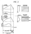
- Fig. 2 is an explanatory diagram of image distortion due to displacement in a displayed image.
- the direction of the displacement is a positive direction from the upper side toward the lower side in the screen.
- the refresh rate of the displayed image depends on the cycle of the vertical synchronization pulse.
- a 1-frame (or 1-field) video signal has an image display period and a vertical blank period of the image.
- the above-described scan displacement occurs linearly from the upper side toward the lower side of the image during the image display period with respect to the time axis, and restores the initial position during the blank period.
- Fig. 2 shows merely an example of the above-described image displacement since it occurs due to the vibration of the image at the display unit or the intentional movement of viewpoint by the viewer.
- the image displacement occurs toward the lower side of the image screen during the first half of the 1 frame, and occurs toward the upper side of the image screen during the last half of the 1 frame.
- Fig. 3 is an explanatory diagram of movement of the image distortion in the displayed image.
- Fig. 4 illustrates the relation between a beat frequency related to the image distortion and image quality.
- Fig. 4 shows subjective image quality evaluation with respect to the beat frequency.
- the distortion on the image screen stands still, i.e., the beat frequency is 0, the distortion on the image screen is not easily perceived.
- the distortion is easily perceived by its movement, and the image quality is degraded once.
- the width of the beat frequency where the distortion is easily perceived will be referred below to as a perceptible beat frequency width.
- the perceptible beat frequency width is ⁇ 10 Hz.
- the perceptible beat frequency width of ⁇ 10 Hz is an example, and actually, the perceptible beat frequency width changes by the influence of the image screen size or the like. Accordingly, it is desirable that the lower limit of the perceptible beat frequency width is ⁇ 3 Hz and the upper limit of the perceptible beat frequency width is ⁇ 20 Hz.
- One of the characteristic features of the present example is appropriately changing the refresh rate so as to prevent perception of the movement of the distortion in the image screen.
- the V timing generator 114 also refers to the random number supplied from the random number generator 113 and generates the vertical synchronization pulse related to the refresh rate while varying the cycle. Accordingly, the refresh rate is distributed at random, and the frequency of the case where the beat frequency enters the range of the perceptible beat frequency width is reduced.
- the display period is fixed, while this blank period is varied at random.
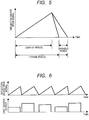
- Fig. 5 illustrates a drive signal for the light irradiation device 1 in the embodiment, and particularly illustrates an example of the waveform of the vertical waveform signal supplied from the deflection device driver 12.
- the display period is fixed, while the blank period is varied at random in correspondence with the random number supplied from the random number generator 113.
- the above-described refresh rate is distributed at random, and the frequency of the case where the beat frequency enters the range of the perceptible beat frequency width is reduced.
- Fig. 6 illustrates the drive signal for the light irradiation device 1 and light source output in the embodiment of the invention.
- the intensity of light emission with the light source 16 per 1 frame (field) is fixed timewisely. That is, when the 1-frame period is long and the refresh rate is low, the light emission intensity is increased. On the other hand, when the 1-frame period is short and the refresh rate is high, the light emission intensity is reduced.
- the length of the 1-frame (field) is varied at random.
- Fig. 7 illustrates the drive signal for the light irradiation device 1 in the second example, and particularly illustrates an example of the waveform of the vertical waveform signal supplied from the deflection device driver 12. As described above, the ratio between the display period and the blank period is fixed.
- the number of image lines displayed by frame may vary in some cases.
- Fig. 8 is a block diagram of the light irradiation device 1 in the second example. Unlike the example shown in Fig. 1 , the video signal supplied from the input terminal 10 is supplied to the light source controller 14 via a scaling unit 18 in correspondence with the varying number of lines. The scaling unit 18 is supplied with the vertical pulse signal and the horizontal pulse signal from the deflection device controller 11.
- the scaling unit 18 performs scaling on the video signal supplied from the input terminal 10. That is, based on the vertical pulse signal and the horizontal pulse signal, the scaling unit 18 detects the number of lines in the processed image frame, performs signal calculation between the lines, generates a video signal corresponding to the current number of lines, and supplies the signal to the light source controller 14.
- the V timing generator 114 generates a vertical pulse signal corresponding to the refresh rate of a displayed image based on the random number supplied from the random number generator 113, in consideration of the perceptible beat frequency width.
- the V timing generator 114 in place of the random number generator 113, generates the vertical pulse based on information on the frequency of vibration and phase supplied from the vibration monitor 116.
- the image displacement occurs due to the vibration of the image at the display unit or the intentional movement of viewpoint by the viewer.
- the vibration of the image at the display unit it may be arranged such that the vibration of e.g. the light irradiation device 1 is monitored so as to prevent easy perception of the distortion of the displayed image.
- the V timing generator 114 When the vibration is within the range of the above-described perceptible beat frequency width with respect to the refresh rate of the video signal supplied to the input terminal 10, i.e., the vertical synchronization frequency, the V timing generator 114 generates the vertical pulse signal such that the refresh rate of the displayed image corresponds with the vibration frequency.
- the beat frequency shown in Fig. 4 is approximately 0 Hz, and it is possible to prevent easy perception of the distortion of displayed image.
- Fig. 9 is a block diagram of the light irradiation device 1 in the third example. Unlike the examples in Fig. 1 and Fig. 8 , the block diagram of Fig. 9 has a vibration monitor 116 in place of the random number generator 113. The V timing generator 114 generates the vertical pulse signal based on the information on the vibration detected with the vibration monitor 116. Note that as in the case of the example shown in Fig. 8 , the block diagram of Fig. 9 has the scaling unit 18; however, the third example is applicable to a configuration similar to that shown in Fig. 1 without scaling unit 18.
- an electromagnetic method As a method for detecting the vibration with the vibration monitor 116, an electromagnetic method, an optical method or a method using a distortion sensor may be employed.
- a coil is placed inside a magnetic field generated with a permanent magnet such that the coil generates an electric signal corresponding to the vibration in accordance with relative movement between the coil and the permanent magnet.
- a photo sensor detects light generated with an oppositely positioned LED (Light Emitting Diode), and the photo sensor generates an electric signal corresponding to the vibration in accordance with relative movement between the photo sensor and the LED.
- LED Light Emitting Diode
- a metal foil distortion sensor which generates an electric signal corresponding to the variation of electric resistance of the metal foil by vibration, or a semiconductor distortion sensor which generates an electric signal corresponding to the variation piezoresistance of the semiconductor may be employed.
- a so-called acceleration sensor is applicable as the vibration monitor 116.
- the deflection device 13 may have the above-described constituent element to generate an electric signal.
- the intentional movement of viewpoint by the viewer is given. It may be arranged such that, for detection of the movement of viewpoint, the light irradiation device 1 has an image pickup device (not shown).
- the V timing generator 114 generates the vertical pulse signal based on the result of addition of the movement of viewpoint detected with the image pickup device to the above-described vibration, in consideration of phase.
- the beat frequency shown in Fig. 4 is approximately 0 Hz, and it is possible to prevent easy perception of distortion of a displayed image.
- the V timing generator 114 when the vibration detected with the vibration monitor 116 is within the range of the above-described perceptible beat frequency width with respect to the refresh rate of the video signal supplied to the input terminal 10 i.e. the vertical synchronization frequency, the V timing generator 114 generates the vertical pulse signal such that the refresh rate of the displayed image corresponds to the above-described vibration frequency.
- the object of the fourth example is attained by other methods than that shown in the third example.
- An example of such methods will be shown in the fourth example which is not part of the claimed invention.
- the frequency of the vertical pulse signal generated with the V timing generator 114 may be changed in correspondence with the range of the vibration frequency in the perceptible beat frequency width with respect to the refresh rate of the video signal supplied to the input terminal 10 i.e. the vertical synchronization frequency.
- the V timing generator 114 when the frequency of the vibration detected with the vibration monitor 116 is within the half of the perceptible beat frequency width shown in Fig. 4 with respect to the refresh rate of the video signal supplied to the input terminal 10 i.e. the vertical synchronization frequency, that is, ⁇ 5 Hz, the V timing generator 114 operates as in the case of the third example which is not part of the claimed invention. That is the V timing generator 114 generates the vertical pulse signal such that the refresh rate of the displayed image corresponds to the vibration frequency.
- the V timing generator 114 when the vibration frequency is ⁇ 5 Hz to ⁇ 10 Hz in the example shown in Fig. 4 , the V timing generator 114 generates the vertical pulse signal such that the absolute value of the refresh rate of the displayed image is different from the vertical synchronization frequency of the video signal supplied to the input terminal 10 by 10 Hz or more. As explained in Fig. 4 , since the distortion of the displayed image is not easily perceived outside the perceptible beat frequency width, the object is attained.
Landscapes
- Engineering & Computer Science (AREA)
- Physics & Mathematics (AREA)
- Computer Hardware Design (AREA)
- General Physics & Mathematics (AREA)
- Theoretical Computer Science (AREA)
- Control Of Indicators Other Than Cathode Ray Tubes (AREA)
- Controls And Circuits For Display Device (AREA)
- Mechanical Optical Scanning Systems (AREA)
- Transforming Electric Information Into Light Information (AREA)
Description
- The present invention relates to a light irradiation device to spatially sequentially scan a spot or a beam of light and irradiate an object with the scanned light, and further to display an image.
- The light irradiation device generates intensity-modulated light, deflects the light while reciprocating it with a mirror or the like in one direction, and further, deflects the light while reciprocating it with the mirror in a direction vertical to the above direction, to irradiate an object with the light and two-dimensionally scan the object. It is considered that the light irradiation device is applicable to an image display device (projector) disclosed in e.g. Japanese Patent Application No.
JP4639973B
Related art is disclosed inUS 2010/ 321750 A1 from which the pre-characterising part ofclaim 1 starts out, and inUS 2011/001888 A1 .US 5680454 A discloses random variation of an image frame rate. - In the above-described scan type light irradiation device, the light-irradiated position in the object timewisely changes. Regarding a position irradiated with light in some moment, displacement with respect to a predetermined reference position will be referred to as scan displacement.
- On the other hand, when the above-described light irradiation device is applied to the image display device, the viewpoint of a viewer who is watching a displayed image moves. The movement of the viewpoint occurs due to vibration of the image at a display unit of the image display device or intentional movement of the viewpoint by the viewer. The displacement with respect to the predetermined reference position of the viewer's viewpoint including these cases will be referred to as image displacement.
- On the retina of the viewer watching the displayed image, an image influenced by the above-described scan displacement and the image displacement is formed. Accordingly, image distortion to be described later perceptionally occurs. For example, when of an image having uniform brightness is displayed, an image with uneven brightness is visually detected.
- Especially, when the difference between the refresh rate determined based on the frame frequency (e.g. 30 Hz) of the image and the cycle of the above-described image displacement is small, since the above-described image distortion slowly moves on the display screen, it attracts the viewer's notice.
- The present invention has been made in view of the above-described problem, and has an object to provide a light irradiation device which prevents detection of distortion of displayed image. To solve the above-described problem, the present invention provides a light irradiation device as defined in the appended claims.
- According to the present invention, it is possible to provide a light irradiation device which prevents easy perception of the distortion of a display image.
- These and other features, objects and advantages of the present invention will become more apparent from the following description when taken in conjunction with the accompanying drawings wherein:
-
Fig. 1 is a block diagram of a light irradiation device in a first example which is not part of the claimed invention; -
Fig. 2 is an explanatory diagram of image distortion due to displacement in a displayed image; -
Fig. 3 is an explanatory diagram of movement of the image distortion in the displayed image; -
Fig. 4 illustrates the relation between a beat frequency related to the image distortion and image quality; -
Fig. 5 illustrates a drive signal for the light irradiation device in an embodiment of the invention; -
Fig. 6 illustrates the drive signal for the light irradiation device and light source output in the embodiment of the invention; -
Fig. 7 illustrates the drive signal for the light irradiation device in a second example which is not part of the claimed invention; -
Fig. 8 is a block diagram of the light irradiation device in the second example; and -
Fig. 9 is a block diagram of the light irradiation device in a third example which is not part of the claimed invention. - Hereinbelow, preferred embodiments of the present invention and illustrative examples will be described in accordance with the accompanying drawings.
-
Fig. 1 is a block diagram of a light irradiation device in a first example. First, the overall explanation will be made with reference toFig. 1 , and thereafter, the characteristic features of the present example will be described. - A video signal inputted from an
input terminal 10 is a video signal for image display, and is supplied to adeflection device controller 11 and alight source controller 14. - The
deflection device controller 11 generates a synchronization signal in a direction vertical to a horizontal direction of a scanned and displayed image, based on the supplied video signal, and supplies the signal to adeflection device driver 12. - The
light source controller 14 generates a luminance control signal to control the luminance of alight source 16 to be described later, based on the luminance of the supplied video signal, and supplies the signal to alight source driver 15. - The
deflection device controller 11 generates e.g. a horizontal pulse signal with an H (Horizontal)timing generator 111 to indicate horizontal synchronization timing of the image based on the supplied video signal, and supplies the signal to anH waveform generator 112. - The
H waveform generator 112 generates e.g. a rectangular horizontal waveform signal for scanning in the horizontal direction based on the supplied horizontal pulse signal, and supplies the signal to thedeflection device driver 12. - Further, the
deflection device controller 11 generates e.g. a vertical pulse signal with a V (Vertical)timing generator 114 to indicate vertical synchronization timing of the image based on the supplied video signal, and supplies the signal to aV waveform generator 115. - The
V waveform generator 115 generates e.g. a rectangular vertical waveform signal for scanning in the vertical direction based on the supplied vertical pulse signal, and supplies the signal to thedeflection device driver 12. - Note that the
V timing generator 114 is also supplied with a random number generated with arandom number generator 113. Further, the horizontal pulse signal and the vertical pulse signal are also supplied to thelight source controller 14. One of the features of the present example is that theV timing generator 114 also refers to the supplied random number to generate the vertical pulse signal so as to control the operations of thelight source controller 14 and theV waveform generator 115. However, this feature will be described later. - The
deflection device driver 12 electric-power amplifies the horizontal waveform signal supplied from theH waveform generator 112 and the vertical waveform signal supplied from theV waveform generator 115, and supplies the signals to adeflection device 13. - The
light source driver 15 electric-power amplifies the luminance control signal supplied from thelight source controller 14, and supplies the signal to thelight source 16. - The
light source 16 generates light corresponding to the luminance of the video signal inputted into theinput terminal 10 based on the supplied power-amplified luminance control signal. - The light generated with the
light source 16 is supplied to anoptical device group 17, and theoptical device group 17 converts the supplied light from e.g. divergent light into collimated light, and supplies the light to thedeflection device 13. - The
deflection device 13 deflects the light, supplied from theoptical device group 17, cyclically in the horizontal direction and the vertical direction, based on the horizontal waveform signal and the vertical waveform signal supplied from thedeflection device driver 12. - With this operation, the light outputted from the
deflection device 13 forms an image corresponding to the luminance of the video signal inputted into theinput terminal 10 on e.g. a display unit provided outside thelight irradiation device 1. - Note that in
Fig. 1 , only one route from thelight source controller 14 to thelight source 16 is shown; however, three routes corresponding to video image R (Red) signal, G (Green) signal and B (Blue) signal may be shown. - Next, the operation related to the
random number generator 113 will be described. - In the present example, the vertical pulse signal generated with the
V timing generator 114 is generated not so as to be completely phase-synchronized with the vertical synchronization signal of the video signal supplied to theinput terminal 10, but to vary based on the random number supplied from therandom number generator 113, in consideration with a perceptible beat frequency width to be described later. The frequency of the vertical pulse signal varies within a range of e.g. ±3 to 20 Hz with the frequency of the vertical synchronization signal of the video supplied to theinput terminal 10 as a center. The vertical pulse signal generated with theV timing generator 114 may or may not be phase-synchronized with the variable vertical pulse signal. - The
light source controller 14 sets the time axis of the luminance control signal to be generated based on the variable vertical pulse signal or the variable horizontal pulse signal. - With the above arrangement, it is possible to prevent easy perception of the distortion of the image displayed at the display unit.
- The distortion of the image will be described in more detail.
-
Fig. 2 is an explanatory diagram of image distortion due to displacement in a displayed image. InFig. 2 , the direction of the displacement is a positive direction from the upper side toward the lower side in the screen. As it is well known, the refresh rate of the displayed image depends on the cycle of the vertical synchronization pulse. Further, a 1-frame (or 1-field) video signal has an image display period and a vertical blank period of the image. - The above-described scan displacement occurs linearly from the upper side toward the lower side of the image during the image display period with respect to the time axis, and restores the initial position during the blank period.
-
Fig. 2 shows merely an example of the above-described image displacement since it occurs due to the vibration of the image at the display unit or the intentional movement of viewpoint by the viewer. In this example, with respect to the time axis, the image displacement occurs toward the lower side of the image screen during the first half of the 1 frame, and occurs toward the upper side of the image screen during the last half of the 1 frame. - An image corresponding to the sum of the scan displacement and the image displacement is perceived on the viewer's retina.
- In this case, even when the luminance of the video signal inputted into the
input terminal 10 is uniform in the entire image screen, it is not even on the viewer's retina, and an image with luminance distortion where the upper side of the image screen is dark while the lower side is bright is perceived. -
Fig. 3 is an explanatory diagram of movement of the image distortion in the displayed image. - When the difference between the cycle of the scan displacement based on a predetermined refresh rate and the cycle of the image displacement due to e.g. eye movement is small, as the luminance distortion slowly moves in the vertical direction on the image screen as shown in
Fig. 3 . This attracts the viewer's attention. -
Fig. 4 illustrates the relation between a beat frequency related to the image distortion and image quality. - The above-described difference between the cycles will be referred to as a beat frequency below.
Fig. 4 shows subjective image quality evaluation with respect to the beat frequency. As it is apparent fromFig. 4 , when the distortion on the image screen stands still, i.e., the beat frequency is 0, the distortion on the image screen is not easily perceived. In accordance with shift of the beat frequency from 0, the distortion is easily perceived by its movement, and the image quality is degraded once. When the beat frequency becomes higher and the moving speed of the distortion is higher, the distortion is not easily perceived. The width of the beat frequency where the distortion is easily perceived will be referred below to as a perceptible beat frequency width. In the example ofFig. 4 , the perceptible beat frequency width is ±10 Hz. - Note that the perceptible beat frequency width of ±10 Hz is an example, and actually, the perceptible beat frequency width changes by the influence of the image screen size or the like. Accordingly, it is desirable that the lower limit of the perceptible beat frequency width is ±3 Hz and the upper limit of the perceptible beat frequency width is ±20 Hz.
- One of the characteristic features of the present example, which is not part of the claimed invention, is appropriately changing the refresh rate so as to prevent perception of the movement of the distortion in the image screen.
- In
Fig. 1 , theV timing generator 114 also refers to the random number supplied from therandom number generator 113 and generates the vertical synchronization pulse related to the refresh rate while varying the cycle. Accordingly, the refresh rate is distributed at random, and the frequency of the case where the beat frequency enters the range of the perceptible beat frequency width is reduced. - With this arrangement, it is possible to provide a light irradiation device which prevents easy perception of the distortion of the displayed image.
- In the embodiment of the invention, as a method for implementation of the first example, in a 1-frame (field) image, the display period is fixed, while this blank period is varied at random.
-
Fig. 5 illustrates a drive signal for thelight irradiation device 1 in the embodiment, and particularly illustrates an example of the waveform of the vertical waveform signal supplied from thedeflection device driver 12. As described above, the display period is fixed, while the blank period is varied at random in correspondence with the random number supplied from therandom number generator 113. With this arrangement, the above-described refresh rate is distributed at random, and the frequency of the case where the beat frequency enters the range of the perceptible beat frequency width is reduced. -
Fig. 6 illustrates the drive signal for thelight irradiation device 1 and light source output in the embodiment of the invention. As described above, in the case where the blank period is varied at random, even when the display period of the image is fixed, since the light emission intensity per unit time varies timewisely, new luminance distortion might be detected. In this case, as shown inFig. 6 , it may be arranged such that the intensity of light emission with thelight source 16 per 1 frame (field) is fixed timewisely. That is, when the 1-frame period is long and the refresh rate is low, the light emission intensity is increased. On the other hand, when the 1-frame period is short and the refresh rate is high, the light emission intensity is reduced. - With this arrangement, it is possible to provide a light irradiation device which prevents easy perception of the distortion of a displayed image, and further, reduces the factor of occurrence of new distortion.
- In the second example, as a method for implementation of the first example, in a 1-frame (field) image, while a fixed ratio is maintained between the display period and the blank period, the length of the 1-frame (field) is varied at random.
-
Fig. 7 illustrates the drive signal for thelight irradiation device 1 in the second example, and particularly illustrates an example of the waveform of the vertical waveform signal supplied from thedeflection device driver 12. As described above, the ratio between the display period and the blank period is fixed. - The number of image lines displayed by frame may vary in some cases.
-
Fig. 8 is a block diagram of thelight irradiation device 1 in the second example. Unlike the example shown inFig. 1 , the video signal supplied from theinput terminal 10 is supplied to thelight source controller 14 via ascaling unit 18 in correspondence with the varying number of lines. The scalingunit 18 is supplied with the vertical pulse signal and the horizontal pulse signal from thedeflection device controller 11. - The scaling
unit 18 performs scaling on the video signal supplied from theinput terminal 10. That is, based on the vertical pulse signal and the horizontal pulse signal, the scalingunit 18 detects the number of lines in the processed image frame, performs signal calculation between the lines, generates a video signal corresponding to the current number of lines, and supplies the signal to thelight source controller 14. - With this arrangement, it is possible to provide a light irradiation device which generates a video signal corresponding to the number of lines of a displayed image, and reduces the factor of occurrence of a new problem.
- In the above described first and second examples, as well as the Embodiment of the Invention, the
V timing generator 114 generates a vertical pulse signal corresponding to the refresh rate of a displayed image based on the random number supplied from therandom number generator 113, in consideration of the perceptible beat frequency width. - In the third example, the
V timing generator 114, in place of therandom number generator 113, generates the vertical pulse based on information on the frequency of vibration and phase supplied from thevibration monitor 116. - As described above, the image displacement occurs due to the vibration of the image at the display unit or the intentional movement of viewpoint by the viewer. Regarding the vibration of the image at the display unit, it may be arranged such that the vibration of e.g. the
light irradiation device 1 is monitored so as to prevent easy perception of the distortion of the displayed image. - When the vibration is within the range of the above-described perceptible beat frequency width with respect to the refresh rate of the video signal supplied to the
input terminal 10, i.e., the vertical synchronization frequency, theV timing generator 114 generates the vertical pulse signal such that the refresh rate of the displayed image corresponds with the vibration frequency. With this arrangement, the beat frequency shown inFig. 4 is approximately 0 Hz, and it is possible to prevent easy perception of the distortion of displayed image. -
Fig. 9 is a block diagram of thelight irradiation device 1 in the third example. Unlike the examples inFig. 1 andFig. 8 , the block diagram ofFig. 9 has avibration monitor 116 in place of therandom number generator 113. TheV timing generator 114 generates the vertical pulse signal based on the information on the vibration detected with thevibration monitor 116. Note that as in the case of the example shown inFig. 8 , the block diagram ofFig. 9 has the scalingunit 18; however, the third example is applicable to a configuration similar to that shown inFig. 1 without scalingunit 18. - As a method for detecting the vibration with the
vibration monitor 116, an electromagnetic method, an optical method or a method using a distortion sensor may be employed. In the electromagnetic method, a coil is placed inside a magnetic field generated with a permanent magnet such that the coil generates an electric signal corresponding to the vibration in accordance with relative movement between the coil and the permanent magnet. In the optical method, a photo sensor detects light generated with an oppositely positioned LED (Light Emitting Diode), and the photo sensor generates an electric signal corresponding to the vibration in accordance with relative movement between the photo sensor and the LED. - As the distortion sensor, a metal foil distortion sensor which generates an electric signal corresponding to the variation of electric resistance of the metal foil by vibration, or a semiconductor distortion sensor which generates an electric signal corresponding to the variation piezoresistance of the semiconductor may be employed. Note that a so-called acceleration sensor is applicable as the
vibration monitor 116. - Since the vibration in the displayed image reflects the vibration of the
deflection device 13, thedeflection device 13 may have the above-described constituent element to generate an electric signal. - As a factor of image displacement, in addition to the vibration of the
light irradiation device 1, the intentional movement of viewpoint by the viewer is given. It may be arranged such that, for detection of the movement of viewpoint, thelight irradiation device 1 has an image pickup device (not shown). TheV timing generator 114 generates the vertical pulse signal based on the result of addition of the movement of viewpoint detected with the image pickup device to the above-described vibration, in consideration of phase. With this arrangement, the beat frequency shown inFig. 4 is approximately 0 Hz, and it is possible to prevent easy perception of distortion of a displayed image. - In the third example, when the vibration detected with the
vibration monitor 116 is within the range of the above-described perceptible beat frequency width with respect to the refresh rate of the video signal supplied to theinput terminal 10 i.e. the vertical synchronization frequency, theV timing generator 114 generates the vertical pulse signal such that the refresh rate of the displayed image corresponds to the above-described vibration frequency. - However, the object of the fourth example is attained by other methods than that shown in the third example. An example of such methods will be shown in the fourth example which is not part of the claimed invention.
- For example, the frequency of the vertical pulse signal generated with the
V timing generator 114 may be changed in correspondence with the range of the vibration frequency in the perceptible beat frequency width with respect to the refresh rate of the video signal supplied to theinput terminal 10 i.e. the vertical synchronization frequency. - In this case, when the frequency of the vibration detected with the
vibration monitor 116 is within the half of the perceptible beat frequency width shown inFig. 4 with respect to the refresh rate of the video signal supplied to theinput terminal 10 i.e. the vertical synchronization frequency, that is, ±5 Hz, theV timing generator 114 operates as in the case of the third example which is not part of the claimed invention. That is theV timing generator 114 generates the vertical pulse signal such that the refresh rate of the displayed image corresponds to the vibration frequency. - On the other hand, when the vibration frequency is ±5 Hz to ±10 Hz in the example shown in
Fig. 4 , theV timing generator 114 generates the vertical pulse signal such that the absolute value of the refresh rate of the displayed image is different from the vertical synchronization frequency of the video signal supplied to theinput terminal 10 by 10 Hz or more. As explained inFig. 4 , since the distortion of the displayed image is not easily perceived outside the perceptible beat frequency width, the object is attained. - With this arrangement, it is possible to provide a light irradiation device which prevents easy perception of the distortion of a displayed image without varying extremely the vertical cycle of the displayed image from the vertical cycle of the supplied video signal.
- The above-described embodiments merely show examples and different embodiments to attain the object of the present invention may be considered within the scope of the present invention.
- While the embodiment has been described in accordance with the present invention, it should be understood that the disclosed embodiments are susceptible of changes and modifications without departing from the scope of the appended claims.
Claims (3)
- A light irradiation device which displays a video image of a video signal by light irradiation, each frame period of a video image comprising an image display period and a vertical blank period, said light irradiation device comprising:a light source controller (14), supplied with a video signal based on a said video image, that generates a luminance control signal based on the video signal;a light source driver (15) that electric-power amplifies the luminance control signal supplied from the light source controller;a light source (16) that generates light luminance-modulated based on the electric-power amplified luminance control signal supplied from the light source driver;a horizontal timing generator (111), supplied with the video signal based on the video image, that generates a horizontal pulse signal indicating horizontal synchronization timing for the video signal;a horizontal waveform generator (112) that generates a horizontal waveform signal for scanning in a horizontal direction of the video image, based on the horizontal pulse signal generated with the horizontal timing generator;a vertical timing generator (114), supplied with the video signal based on the video image, that generates a vertical pulse signal;a vertical waveform generator (115) that generates a vertical waveform signal for scanning in a vertical direction of the video image, based on the vertical pulse signal generated with the vertical timing generator;a deflection device driver (12), supplied with the horizontal waveform signal generated with the horizontal waveform generator and the vertical waveform signal generated with the vertical waveform generator, that electric-power amplifies and outputs the signals; anda deflection device (13), supplied with the light generated with the light source, that deflects the light in the horizontal direction and the vertical direction, based on the horizontal waveform signal and the vertical waveform signal outputted from the deflection device driver,characterised by:
a random number generator (113) that generates a random number, wherein:the vertical timing generator (114) is further supplied with the random number generated by the random number generator and generates the vertical pulse signal with its frequency varied at random based on the random number, by a predetermined or greater frequency width, with respect to a vertical synchronization frequency of the video signal,wherein the image display period of a frame period of a video image of said video signal is fixed while a vertical blank period of a said frame period is varied at random in correspondence with the supplied random number; andthe light source controller (14) is also supplied with the vertical pulse signal generated with the vertical timing generator, said light source controller being adapted to vary the luminance of the luminance control signal for each frame in correspondence with the cycle of the vertical pulse signal so that light emission intensity of the light source is increased when a said frame period is longer and is decreased when a said frame period is shorter. - The light irradiation device according to claim 1, wherein the predetermined frequency width in the vertical timing generator (114) is determined in correspondence with a perceptible beat frequency width in which a beat occurring in a displayed image is perceived due to a difference between a vertical synchronization frequency of the video signal supplied to the light irradiation device and a frequency of the vertical pulse signal generated with the vertical timing generator.
- The light irradiation device according to claim 2, wherein an absolute value of the perceptible beat frequency width is equal to or higher than 3 Hz and equal to or lower than 20 Hz.
Applications Claiming Priority (1)
| Application Number | Priority Date | Filing Date | Title |
|---|---|---|---|
| JP2013061652A JP2014186206A (en) | 2013-03-25 | 2013-03-25 | Light irradiation device |
Publications (2)
| Publication Number | Publication Date |
|---|---|
| EP2784769A1 EP2784769A1 (en) | 2014-10-01 |
| EP2784769B1 true EP2784769B1 (en) | 2019-04-10 |
Family
ID=50159012
Family Applications (1)
| Application Number | Title | Priority Date | Filing Date |
|---|---|---|---|
| EP14000573.7A Active EP2784769B1 (en) | 2013-03-25 | 2014-02-18 | Scan-type light irradiation device for image display |
Country Status (4)
| Country | Link |
|---|---|
| US (2) | US9412338B2 (en) |
| EP (1) | EP2784769B1 (en) |
| JP (1) | JP2014186206A (en) |
| CN (1) | CN104079852B (en) |
Families Citing this family (4)
| Publication number | Priority date | Publication date | Assignee | Title |
|---|---|---|---|---|
| JP6144976B2 (en) * | 2013-06-26 | 2017-06-07 | キヤノン株式会社 | Information processing apparatus, assembly apparatus, information processing method, and program |
| JP6420530B2 (en) | 2013-06-26 | 2018-11-07 | キヤノン株式会社 | Information processing apparatus, measurement system, control system, light quantity determination method, program, and storage medium |
| CN106959461B (en) * | 2017-02-28 | 2019-11-22 | 清华大学 | Navigation and deformation monitoring method, monitoring terminal, management center and navigation receiver |
| CN110648643B (en) * | 2019-09-30 | 2021-05-11 | 京东方科技集团股份有限公司 | A voltage regulation method, device and display device |
Citations (1)
| Publication number | Priority date | Publication date | Assignee | Title |
|---|---|---|---|---|
| US5680454A (en) * | 1995-08-04 | 1997-10-21 | Hughes Electronics | Method and system for anti-piracy using frame rate dithering |
Family Cites Families (8)
| Publication number | Priority date | Publication date | Assignee | Title |
|---|---|---|---|---|
| US10247A (en) * | 1853-11-22 | Joining and riveting metallic plates | ||
| JPH01265293A (en) * | 1988-04-15 | 1989-10-23 | Sharp Corp | Miniature display device |
| JP4639973B2 (en) | 2005-06-07 | 2011-02-23 | カシオ計算機株式会社 | Image projection device |
| US8427727B2 (en) * | 2008-01-22 | 2013-04-23 | Alcatel Lucent | Oscillating mirror for image projection |
| JP2010256862A (en) * | 2009-04-01 | 2010-11-11 | Seiko Epson Corp | Mirror device drive control device and projector |
| US8331005B2 (en) * | 2009-04-24 | 2012-12-11 | National Semiconductor Corporation | Method and system for providing resonant frequency change compensation in a drive signal for a MEMS scanner |
| US8248541B2 (en) * | 2009-07-02 | 2012-08-21 | Microvision, Inc. | Phased locked resonant scanning display projection |
| JP5790040B2 (en) * | 2011-03-11 | 2015-10-07 | ソニー株式会社 | Illumination device and display device |
-
2013
- 2013-03-25 JP JP2013061652A patent/JP2014186206A/en active Pending
-
2014
- 2014-02-18 EP EP14000573.7A patent/EP2784769B1/en active Active
- 2014-02-20 US US14/184,737 patent/US9412338B2/en not_active Expired - Fee Related
- 2014-02-20 CN CN201410058450.6A patent/CN104079852B/en not_active Expired - Fee Related
-
2016
- 2016-07-07 US US15/204,024 patent/US9972278B2/en active Active
Patent Citations (1)
| Publication number | Priority date | Publication date | Assignee | Title |
|---|---|---|---|---|
| US5680454A (en) * | 1995-08-04 | 1997-10-21 | Hughes Electronics | Method and system for anti-piracy using frame rate dithering |
Also Published As
| Publication number | Publication date |
|---|---|
| CN104079852A (en) | 2014-10-01 |
| US9972278B2 (en) | 2018-05-15 |
| US9412338B2 (en) | 2016-08-09 |
| US20160314764A1 (en) | 2016-10-27 |
| US20140285541A1 (en) | 2014-09-25 |
| EP2784769A1 (en) | 2014-10-01 |
| CN104079852B (en) | 2017-10-13 |
| JP2014186206A (en) | 2014-10-02 |
Similar Documents
| Publication | Publication Date | Title |
|---|---|---|
| CN102396237B (en) | Video display device, spectacles for viewing video, and system provided with video display device and spectacles for viewing video | |
| US9972278B2 (en) | Light irradiation device | |
| EP2876636B1 (en) | Method of driving display panel and display apparatus for performing the same | |
| US8068087B2 (en) | Methods and systems for reduced flickering and blur | |
| US20120081419A1 (en) | Image display apparatus and control method thereof | |
| KR20100097190A (en) | Stereocopic visualisation | |
| JP4525946B2 (en) | Image processing apparatus, image display apparatus, and image processing method | |
| US20110193888A1 (en) | Image display device | |
| JP5438206B2 (en) | Video display device | |
| JP5284304B2 (en) | Synchronization signal generating device and display device | |
| CN111630585B (en) | Variable emission period for scanned beam displays | |
| JP2014130256A (en) | Image display device, image display method, and program | |
| JP3674606B2 (en) | Light quantity modulation device, display system, and light quantity modulation method | |
| KR20110044144A (en) | Image processing apparatus and control method thereof | |
| JP2015118181A (en) | Image display device and method for controlling the same | |
| US20150062103A1 (en) | Display apparatus, light-emitting device, and control method of display apparatus | |
| TWI427611B (en) | Overdriving value generating method | |
| US20130033515A1 (en) | Image Display Apparatus and Image Display Method | |
| EP2109094A1 (en) | LCD inversion control | |
| JP3958254B2 (en) | Liquid crystal display device and liquid crystal display method | |
| KR102883429B1 (en) | Display device and method of driving for the display device | |
| JP2016048298A (en) | Light emission control device, light emission control method, and display device | |
| JP2012008199A (en) | Display control device, display system and display control method | |
| US10440317B2 (en) | Video processing device | |
| JP2012078589A (en) | Image display device and control method therefor |
Legal Events
| Date | Code | Title | Description |
|---|---|---|---|
| 17P | Request for examination filed |
Effective date: 20140325 |
|
| AK | Designated contracting states |
Kind code of ref document: A1 Designated state(s): AL AT BE BG CH CY CZ DE DK EE ES FI FR GB GR HR HU IE IS IT LI LT LU LV MC MK MT NL NO PL PT RO RS SE SI SK SM TR |
|
| AX | Request for extension of the european patent |
Extension state: BA ME |
|
| PUAI | Public reference made under article 153(3) epc to a published international application that has entered the european phase |
Free format text: ORIGINAL CODE: 0009012 |
|
| STAA | Information on the status of an ep patent application or granted ep patent |
Free format text: STATUS: EXAMINATION IS IN PROGRESS |
|
| 17Q | First examination report despatched |
Effective date: 20170912 |
|
| GRAP | Despatch of communication of intention to grant a patent |
Free format text: ORIGINAL CODE: EPIDOSNIGR1 |
|
| STAA | Information on the status of an ep patent application or granted ep patent |
Free format text: STATUS: GRANT OF PATENT IS INTENDED |
|
| INTG | Intention to grant announced |
Effective date: 20180921 |
|
| GRAS | Grant fee paid |
Free format text: ORIGINAL CODE: EPIDOSNIGR3 |
|
| GRAA | (expected) grant |
Free format text: ORIGINAL CODE: 0009210 |
|
| STAA | Information on the status of an ep patent application or granted ep patent |
Free format text: STATUS: THE PATENT HAS BEEN GRANTED |
|
| AK | Designated contracting states |
Kind code of ref document: B1 Designated state(s): AL AT BE BG CH CY CZ DE DK EE ES FI FR GB GR HR HU IE IS IT LI LT LU LV MC MK MT NL NO PL PT RO RS SE SI SK SM TR |
|
| REG | Reference to a national code |
Ref country code: GB Ref legal event code: FG4D |
|
| REG | Reference to a national code |
Ref country code: CH Ref legal event code: EP Ref country code: AT Ref legal event code: REF Ref document number: 1119752 Country of ref document: AT Kind code of ref document: T Effective date: 20190415 |
|
| REG | Reference to a national code |
Ref country code: DE Ref legal event code: R096 Ref document number: 602014044283 Country of ref document: DE |
|
| REG | Reference to a national code |
Ref country code: IE Ref legal event code: FG4D |
|
| REG | Reference to a national code |
Ref country code: NL Ref legal event code: MP Effective date: 20190410 |
|
| REG | Reference to a national code |
Ref country code: LT Ref legal event code: MG4D |
|
| REG | Reference to a national code |
Ref country code: AT Ref legal event code: MK05 Ref document number: 1119752 Country of ref document: AT Kind code of ref document: T Effective date: 20190410 |
|
| PG25 | Lapsed in a contracting state [announced via postgrant information from national office to epo] |
Ref country code: NL Free format text: LAPSE BECAUSE OF FAILURE TO SUBMIT A TRANSLATION OF THE DESCRIPTION OR TO PAY THE FEE WITHIN THE PRESCRIBED TIME-LIMIT Effective date: 20190410 |
|
| PG25 | Lapsed in a contracting state [announced via postgrant information from national office to epo] |
Ref country code: SE Free format text: LAPSE BECAUSE OF FAILURE TO SUBMIT A TRANSLATION OF THE DESCRIPTION OR TO PAY THE FEE WITHIN THE PRESCRIBED TIME-LIMIT Effective date: 20190410 Ref country code: ES Free format text: LAPSE BECAUSE OF FAILURE TO SUBMIT A TRANSLATION OF THE DESCRIPTION OR TO PAY THE FEE WITHIN THE PRESCRIBED TIME-LIMIT Effective date: 20190410 Ref country code: LT Free format text: LAPSE BECAUSE OF FAILURE TO SUBMIT A TRANSLATION OF THE DESCRIPTION OR TO PAY THE FEE WITHIN THE PRESCRIBED TIME-LIMIT Effective date: 20190410 Ref country code: PT Free format text: LAPSE BECAUSE OF FAILURE TO SUBMIT A TRANSLATION OF THE DESCRIPTION OR TO PAY THE FEE WITHIN THE PRESCRIBED TIME-LIMIT Effective date: 20190910 Ref country code: HR Free format text: LAPSE BECAUSE OF FAILURE TO SUBMIT A TRANSLATION OF THE DESCRIPTION OR TO PAY THE FEE WITHIN THE PRESCRIBED TIME-LIMIT Effective date: 20190410 Ref country code: AL Free format text: LAPSE BECAUSE OF FAILURE TO SUBMIT A TRANSLATION OF THE DESCRIPTION OR TO PAY THE FEE WITHIN THE PRESCRIBED TIME-LIMIT Effective date: 20190410 Ref country code: NO Free format text: LAPSE BECAUSE OF FAILURE TO SUBMIT A TRANSLATION OF THE DESCRIPTION OR TO PAY THE FEE WITHIN THE PRESCRIBED TIME-LIMIT Effective date: 20190710 Ref country code: FI Free format text: LAPSE BECAUSE OF FAILURE TO SUBMIT A TRANSLATION OF THE DESCRIPTION OR TO PAY THE FEE WITHIN THE PRESCRIBED TIME-LIMIT Effective date: 20190410 |
|
| PG25 | Lapsed in a contracting state [announced via postgrant information from national office to epo] |
Ref country code: PL Free format text: LAPSE BECAUSE OF FAILURE TO SUBMIT A TRANSLATION OF THE DESCRIPTION OR TO PAY THE FEE WITHIN THE PRESCRIBED TIME-LIMIT Effective date: 20190410 Ref country code: GR Free format text: LAPSE BECAUSE OF FAILURE TO SUBMIT A TRANSLATION OF THE DESCRIPTION OR TO PAY THE FEE WITHIN THE PRESCRIBED TIME-LIMIT Effective date: 20190711 Ref country code: LV Free format text: LAPSE BECAUSE OF FAILURE TO SUBMIT A TRANSLATION OF THE DESCRIPTION OR TO PAY THE FEE WITHIN THE PRESCRIBED TIME-LIMIT Effective date: 20190410 Ref country code: RS Free format text: LAPSE BECAUSE OF FAILURE TO SUBMIT A TRANSLATION OF THE DESCRIPTION OR TO PAY THE FEE WITHIN THE PRESCRIBED TIME-LIMIT Effective date: 20190410 Ref country code: BG Free format text: LAPSE BECAUSE OF FAILURE TO SUBMIT A TRANSLATION OF THE DESCRIPTION OR TO PAY THE FEE WITHIN THE PRESCRIBED TIME-LIMIT Effective date: 20190710 |
|
| PG25 | Lapsed in a contracting state [announced via postgrant information from national office to epo] |
Ref country code: IS Free format text: LAPSE BECAUSE OF FAILURE TO SUBMIT A TRANSLATION OF THE DESCRIPTION OR TO PAY THE FEE WITHIN THE PRESCRIBED TIME-LIMIT Effective date: 20190810 Ref country code: AT Free format text: LAPSE BECAUSE OF FAILURE TO SUBMIT A TRANSLATION OF THE DESCRIPTION OR TO PAY THE FEE WITHIN THE PRESCRIBED TIME-LIMIT Effective date: 20190410 |
|
| REG | Reference to a national code |
Ref country code: DE Ref legal event code: R097 Ref document number: 602014044283 Country of ref document: DE |
|
| PG25 | Lapsed in a contracting state [announced via postgrant information from national office to epo] |
Ref country code: DK Free format text: LAPSE BECAUSE OF FAILURE TO SUBMIT A TRANSLATION OF THE DESCRIPTION OR TO PAY THE FEE WITHIN THE PRESCRIBED TIME-LIMIT Effective date: 20190410 Ref country code: EE Free format text: LAPSE BECAUSE OF FAILURE TO SUBMIT A TRANSLATION OF THE DESCRIPTION OR TO PAY THE FEE WITHIN THE PRESCRIBED TIME-LIMIT Effective date: 20190410 Ref country code: RO Free format text: LAPSE BECAUSE OF FAILURE TO SUBMIT A TRANSLATION OF THE DESCRIPTION OR TO PAY THE FEE WITHIN THE PRESCRIBED TIME-LIMIT Effective date: 20190410 Ref country code: SK Free format text: LAPSE BECAUSE OF FAILURE TO SUBMIT A TRANSLATION OF THE DESCRIPTION OR TO PAY THE FEE WITHIN THE PRESCRIBED TIME-LIMIT Effective date: 20190410 Ref country code: CZ Free format text: LAPSE BECAUSE OF FAILURE TO SUBMIT A TRANSLATION OF THE DESCRIPTION OR TO PAY THE FEE WITHIN THE PRESCRIBED TIME-LIMIT Effective date: 20190410 |
|
| PLBE | No opposition filed within time limit |
Free format text: ORIGINAL CODE: 0009261 |
|
| STAA | Information on the status of an ep patent application or granted ep patent |
Free format text: STATUS: NO OPPOSITION FILED WITHIN TIME LIMIT |
|
| PG25 | Lapsed in a contracting state [announced via postgrant information from national office to epo] |
Ref country code: IT Free format text: LAPSE BECAUSE OF FAILURE TO SUBMIT A TRANSLATION OF THE DESCRIPTION OR TO PAY THE FEE WITHIN THE PRESCRIBED TIME-LIMIT Effective date: 20190410 Ref country code: SM Free format text: LAPSE BECAUSE OF FAILURE TO SUBMIT A TRANSLATION OF THE DESCRIPTION OR TO PAY THE FEE WITHIN THE PRESCRIBED TIME-LIMIT Effective date: 20190410 |
|
| 26N | No opposition filed |
Effective date: 20200113 |
|
| PG25 | Lapsed in a contracting state [announced via postgrant information from national office to epo] |
Ref country code: TR Free format text: LAPSE BECAUSE OF FAILURE TO SUBMIT A TRANSLATION OF THE DESCRIPTION OR TO PAY THE FEE WITHIN THE PRESCRIBED TIME-LIMIT Effective date: 20190410 |
|
| PG25 | Lapsed in a contracting state [announced via postgrant information from national office to epo] |
Ref country code: SI Free format text: LAPSE BECAUSE OF FAILURE TO SUBMIT A TRANSLATION OF THE DESCRIPTION OR TO PAY THE FEE WITHIN THE PRESCRIBED TIME-LIMIT Effective date: 20190410 |
|
| REG | Reference to a national code |
Ref country code: CH Ref legal event code: PL |
|
| GBPC | Gb: european patent ceased through non-payment of renewal fee |
Effective date: 20200218 |
|
| REG | Reference to a national code |
Ref country code: BE Ref legal event code: MM Effective date: 20200229 |
|
| PG25 | Lapsed in a contracting state [announced via postgrant information from national office to epo] |
Ref country code: LU Free format text: LAPSE BECAUSE OF NON-PAYMENT OF DUE FEES Effective date: 20200218 Ref country code: MC Free format text: LAPSE BECAUSE OF FAILURE TO SUBMIT A TRANSLATION OF THE DESCRIPTION OR TO PAY THE FEE WITHIN THE PRESCRIBED TIME-LIMIT Effective date: 20190410 |
|
| PG25 | Lapsed in a contracting state [announced via postgrant information from national office to epo] |
Ref country code: LI Free format text: LAPSE BECAUSE OF NON-PAYMENT OF DUE FEES Effective date: 20200229 Ref country code: CH Free format text: LAPSE BECAUSE OF NON-PAYMENT OF DUE FEES Effective date: 20200229 |
|
| PG25 | Lapsed in a contracting state [announced via postgrant information from national office to epo] |
Ref country code: GB Free format text: LAPSE BECAUSE OF NON-PAYMENT OF DUE FEES Effective date: 20200218 Ref country code: IE Free format text: LAPSE BECAUSE OF NON-PAYMENT OF DUE FEES Effective date: 20200218 |
|
| PG25 | Lapsed in a contracting state [announced via postgrant information from national office to epo] |
Ref country code: BE Free format text: LAPSE BECAUSE OF NON-PAYMENT OF DUE FEES Effective date: 20200229 |
|
| PG25 | Lapsed in a contracting state [announced via postgrant information from national office to epo] |
Ref country code: MT Free format text: LAPSE BECAUSE OF FAILURE TO SUBMIT A TRANSLATION OF THE DESCRIPTION OR TO PAY THE FEE WITHIN THE PRESCRIBED TIME-LIMIT Effective date: 20190410 Ref country code: CY Free format text: LAPSE BECAUSE OF FAILURE TO SUBMIT A TRANSLATION OF THE DESCRIPTION OR TO PAY THE FEE WITHIN THE PRESCRIBED TIME-LIMIT Effective date: 20190410 |
|
| PG25 | Lapsed in a contracting state [announced via postgrant information from national office to epo] |
Ref country code: MK Free format text: LAPSE BECAUSE OF FAILURE TO SUBMIT A TRANSLATION OF THE DESCRIPTION OR TO PAY THE FEE WITHIN THE PRESCRIBED TIME-LIMIT Effective date: 20190410 |
|
| PGFP | Annual fee paid to national office [announced via postgrant information from national office to epo] |
Ref country code: FR Payment date: 20230110 Year of fee payment: 10 |
|
| PGFP | Annual fee paid to national office [announced via postgrant information from national office to epo] |
Ref country code: DE Payment date: 20221229 Year of fee payment: 10 |
|
| REG | Reference to a national code |
Ref country code: DE Ref legal event code: R119 Ref document number: 602014044283 Country of ref document: DE |
|
| PG25 | Lapsed in a contracting state [announced via postgrant information from national office to epo] |
Ref country code: DE Free format text: LAPSE BECAUSE OF NON-PAYMENT OF DUE FEES Effective date: 20240903 |
|
| PG25 | Lapsed in a contracting state [announced via postgrant information from national office to epo] |
Ref country code: FR Free format text: LAPSE BECAUSE OF NON-PAYMENT OF DUE FEES Effective date: 20240229 |
|
| PG25 | Lapsed in a contracting state [announced via postgrant information from national office to epo] |
Ref country code: FR Free format text: LAPSE BECAUSE OF NON-PAYMENT OF DUE FEES Effective date: 20240229 Ref country code: DE Free format text: LAPSE BECAUSE OF NON-PAYMENT OF DUE FEES Effective date: 20240903 |