EP2784425A1 - Heat exchanger, especially condenser - Google Patents
Heat exchanger, especially condenser Download PDFInfo
- Publication number
- EP2784425A1 EP2784425A1 EP20130461512 EP13461512A EP2784425A1 EP 2784425 A1 EP2784425 A1 EP 2784425A1 EP 20130461512 EP20130461512 EP 20130461512 EP 13461512 A EP13461512 A EP 13461512A EP 2784425 A1 EP2784425 A1 EP 2784425A1
- Authority
- EP
- European Patent Office
- Prior art keywords
- core
- receiver
- heat exchanger
- fluid
- connecting means
- Prior art date
- Legal status (The legal status is an assumption and is not a legal conclusion. Google has not performed a legal analysis and makes no representation as to the accuracy of the status listed.)
- Granted
Links
Images

Classifications
-
- F—MECHANICAL ENGINEERING; LIGHTING; HEATING; WEAPONS; BLASTING
- F25—REFRIGERATION OR COOLING; COMBINED HEATING AND REFRIGERATION SYSTEMS; HEAT PUMP SYSTEMS; MANUFACTURE OR STORAGE OF ICE; LIQUEFACTION SOLIDIFICATION OF GASES
- F25B—REFRIGERATION MACHINES, PLANTS OR SYSTEMS; COMBINED HEATING AND REFRIGERATION SYSTEMS; HEAT PUMP SYSTEMS
- F25B39/00—Evaporators; Condensers
- F25B39/04—Condensers
-
- F—MECHANICAL ENGINEERING; LIGHTING; HEATING; WEAPONS; BLASTING
- F28—HEAT EXCHANGE IN GENERAL
- F28D—HEAT-EXCHANGE APPARATUS, NOT PROVIDED FOR IN ANOTHER SUBCLASS, IN WHICH THE HEAT-EXCHANGE MEDIA DO NOT COME INTO DIRECT CONTACT
- F28D9/00—Heat-exchange apparatus having stationary plate-like or laminated conduit assemblies for both heat-exchange media, the media being in contact with different sides of a conduit wall
- F28D9/0031—Heat-exchange apparatus having stationary plate-like or laminated conduit assemblies for both heat-exchange media, the media being in contact with different sides of a conduit wall the conduits for one heat-exchange medium being formed by paired plates touching each other
- F28D9/0043—Heat-exchange apparatus having stationary plate-like or laminated conduit assemblies for both heat-exchange media, the media being in contact with different sides of a conduit wall the conduits for one heat-exchange medium being formed by paired plates touching each other the plates having openings therein for circulation of at least one heat-exchange medium from one conduit to another
- F28D9/005—Heat-exchange apparatus having stationary plate-like or laminated conduit assemblies for both heat-exchange media, the media being in contact with different sides of a conduit wall the conduits for one heat-exchange medium being formed by paired plates touching each other the plates having openings therein for circulation of at least one heat-exchange medium from one conduit to another the plates having openings therein for both heat-exchange media
-
- F—MECHANICAL ENGINEERING; LIGHTING; HEATING; WEAPONS; BLASTING
- F25—REFRIGERATION OR COOLING; COMBINED HEATING AND REFRIGERATION SYSTEMS; HEAT PUMP SYSTEMS; MANUFACTURE OR STORAGE OF ICE; LIQUEFACTION SOLIDIFICATION OF GASES
- F25B—REFRIGERATION MACHINES, PLANTS OR SYSTEMS; COMBINED HEATING AND REFRIGERATION SYSTEMS; HEAT PUMP SYSTEMS
- F25B2339/00—Details of evaporators; Details of condensers
- F25B2339/04—Details of condensers
- F25B2339/044—Condensers with an integrated receiver
Definitions
- the invention relates to a heat exchanger, especially a condenser for an air conditioning unit. While being developed to be used in automotive vehicles, the invention shall not be limited thereto.
- condensers located in a vehicle front end. They are made of core comprising tubes and fins located between the tubes. They provide a heat exchange between a refrigerant fluid flowing in the tubes and an air flow flowing through the fins.
- the core is generally provided with a condensing portion and a sub cooling portion in which the refrigerant fluid flows coming from a receiver attached to the core.
- Many solutions have been proposed to attach and connect the receiver and the core.
- condensers comprising a core made of plates stacked along a stacking direction, said plates alternatively defining a flow passage for the refrigerant fluid and a cooling liquid to have both fluids exchanging heat there between.
- the condensing portion and the sub cooling portions are defined by a corresponding number of plates.
- the receiver is integrated between the two portions of the core.
- the invention aims at mitigating such drawbacks and proposes in that view a heat exchanger between a first fluid and a second fluid, especially a condenser for an air conditioning unit, said heat exchanger comprising a first core defining flow passages stacked alternatively along a stacking direction for said first fluid and said second fluid to have both fluids exchanging heat there between, said heat exchanger further comprising connecting means to have said first fluid flowing between said first core and a receiver for said first fluid, said connecting means being configured to support said receiver in a shifted position relatively to said first core along said stacking direction and in parallel with a side of said first core, said side being parallel to said stacking direction.
- the receiver By giving the receiver the opportunity to locate the receiver along a lateral side of the core, said receiver further being shifted relatively to said lateral side, the possibility to adapt the overall packaging of the heat exchanger to different constraints is enhanced.
- the invention especially decreases the overall packaging along said stacking direction while still optimizing the integration of the receiver in the heat exchanger by achieving both supporting and fluid connecting functions with the same means.
- the invention further gives the possibility to use receiver technologies coming from tubes and fins heat exchangers.
- the invention relates to a heat exchanger between a first and a second fluid, especially a condenser for an air conditioning unit, more especially for automotive applications.
- Said first fluid is for instance a refrigerant fluid, as the fluid known under R134a or R1234yf.
- the heat exchanger is configured to have it enter under gaseous phase and exit under liquid phase.
- the second fluid is for instance a cooling liquid as water added with some anti freeze like glycol.
- the cooling liquid may be a mixture of water and glycol.
- Said heat exchanger comprises a first core 1 and optionally a second core 5 stacked with said first core along a stacking direction D.
- said first core is especially configured to achieve a condensation of said refrigerant fluid and said second core to achieve a subcooling thereof.
- Said cores 1, 5 define flow passages for said first fluid and said second fluid stacked alternatively along said stacking direction to have both fluids exchanging heat there between.
- Said cores 1, 5 are for instance made of plates 3 (better visible on figure 4 ) stacked along said stacking direction to define said passages.
- a same plate defines a passage for the first fluid together with one of the adjoining plate and a passage for the second fluid with the other adjoining plate.
- Said plates are for instance obtained by stamping a laminated plate of metal, especially aluminium and/or an aluminium alloy.
- Said plates 3 may be of rectangular shape.
- said first and second cores 1, 5 have a parallelepipedic shape with lateral sides 1a, 1b, 1c, 1d, 5a, 5b, 5c, 5d parallel to said stacking direction, top sides 2a, 5a and bottom sides 2b, 5b parallel to said stacking direction.
- Said plates 3 comprise for instance a rising edge, defining with a bottom of said plate a volume in which said fluids flow.
- Said plates are provided, for instance, with four holes managed in the bottom of said plates, two of said holes being provided for the circulation of the first fluid and two other of said holes for the circulation of the second fluid.
- the holes for the circulation of the first fluid may be located along a first longitudinal side of said plate and the holes for the circulation of the other fluid along the other longitudinal side.
- Said heat exchanger further comprise collecting means to have said first fluid flowing from one of said passage for the first to the next passage for the first fluid and said second fluid flowing from one of said passage for the second fluid to the next passage for the second fluid.
- Said collecting means are for instance constituted by two embossed portion of said plate bottom, each provided with one of said holes. More precisely, two of said holes are provided in a flat portion of said plates bottom and the two others are provided at the top of said embossed portion. When stacked, the two holes of the embossed portion of one said plate are in communication with the two holes provided in the flat portion of the bottom of one of the adjoining plate. As a result, one of said fluid flows in the passage provided between said two plates and the other of said fluid flows through said holes from one of the adjoining passage to the other of the adjoining passage.
- Said plates 3 of both first and second cores may be of the same type, the differences between the two cores optionally being the number of plates which are used to constitute them and the location of the holes in the plates . It can also be seen that said plates are stacked from bottom to top in said first core 1 and from top to bottom in said second core 5.
- said heat exchanger further comprises here a receiver 7 for said first fluid.
- Said receiver is connected upstream with said first core 1 and optionally downstream with said second core 5.
- said receiver aims at separating the part of said refrigerant fluid potentially still in a gaseous phase from the part in liquid phase to let only said liquid phase part flow downstream. It may also aim at filtering and/or drying said refrigerant fluid.
- Said receiver 7 comprises for instance a cylindrical tank closed at its both longitudinal extremities 8a, 8b. It may be provided with a removable cap at one 8b of said longitudinal extremity, said removable cap giving the opportunity to access to an internal volume of said receiver 7 into which said first fluid flows, when removed.
- said heat exchanger further comprises connecting means 9 to have said first fluid flowing between said first core 1 and said receiver 7.
- Said connecting means 9 are here also configured to have said first fluid flowing between said receiver 7 and said second core 5.
- Said connecting means 9 are further configured to support said receiver 7 in a shifted position relatively to said first core 1 along said stacking direction and in parallel with a lateral side of said first core 1, here said lateral side 1a.
- the invention thus increase the possibility of integration of said heat exchanger in its environment. It further gives the possibility to simultaneously attach the receiver to said first and/or second cores 1, 5 and to achieve a fluid circulation there between.
- the first fluid enters the first core 1 trough an inlet flange 10 provided on a top end plate of said first core 1 to flow between the plates 3 of said first core 1. It then flows in said receiver 7 and from said receiver 7 to said second core 5 through respective channels 14a, 14b provided in said connecting means 9. It finally flows between the plates 3 of said second core 5 to exit through an outlet flange 11 provided at a bottom end plate of said second core 5.
- Said connecting means are also advantageously configured to achieve a second fluid circulation between said first and said second core 1, 5.
- said second fluid can enter the second core 5 through an inlet flange 12 and the first core 1 through a second fluid inlet pathway 15 provided in said connecting means 9, said second fluid inlet pathway communicating with said first and said second cores 1, 5 . It then flow simultaneously between the plates 3 of both cores 1, 5. It finally exit said second cores 5 through an outlet flange 13 and said first core 1 through a second fluid outlet pathway 16 provided in said connecting means 9, said second fluid outlet pathway communicating with said first and second cores 1, 5.
- first core 1 and said second core 5 may have independent circuits for said second fluid, said cores having then their own inlet and outlet flanges for said second fluid.
- the connecting means 9 may be configured to support said receiver 7 along any direction, especially said stacking direction as illustrated.
- Said connecting means 7 are here configured to support said receiver 7 along said first core 1 and said second core 5.
- Said receiver 7 may be higher than said first and second core 1, 5 taken together with said connecting means 9 along said stacking direction.
- one 8a of said receiver longitudinal extremities extend above said first core 1 and/or the other 8b of its longitudinal extremities extend below said second core 5.
- said connecting means 9 are at least in part located between said first and said second cores 1, 5, especially between a bottom end plate 3a of said first core 1 and a top end plate 3b of said second core 5.
- Said end plates 3a, 3b are here the first plate of the stacked plates of each core 1, 5 ( figure 4 ).
- Said connecting means 9 are here provided with connecting brackets 20, 22 for said receiver and/or at least one connecting bracket 24 to a support.
- Said connecting means 9 comprise advantageously a frame 18 extending along said end plate of said first core 1 and/or said second core 5 and additional components to connect and support said receiver 7 along said lateral side 1a, said longitudinal extremity 8b of said receiver 7 being shifted from said frame 18 along said stacking direction.
- Said frame 18 is here sandwiched between said first and second cores 1, 5.
- Said frame have for instance a rectangular hollow shape with an intermediate branch 19 connecting two longitudinal sides thereof.
- Said connecting bracket 24 to a support extends from said frame 18.
- Said channels 14a, 14b comprise a first portion 26 defined in said frame 18 and a second portion 28 in fluid communication with said first portion 26.
- Said connecting means 9 comprise pipes 30 defining said second portion 28.
- said pipes 30 extend along said receiver 7.
- Said pipes 30 support here a first one 20 of said connecting brackets for said receiver 7, called base bracket, said base bracket 20 being connected to a longitudinal end of said receiver 7, here said longitudinal extremity 8b closed by a removable cap.
- Said base bracket 20 comprises for instance three branches 32, 34, 36 configured here in a star.
- a first 32 of said branches is attached to a first of said pipes 30 communicating with said first core 1 and is provided with an inlet flange 33 communicating with said receiver 7.
- a second 34 of said branches is attached to a second of said pipes 30 communicating with said second core 5 and is provided with an outlet flange 35 communicating with said receiver 7. The first fluid circulation from said first core 1 to said second core 5 through said receiver 7 is thus established.
- a third 36 of said branches is provided with a trough hole 37 trough which a screw 50 attaches said receiver 7 to said base bracket 20 thanks to a threaded hole (not shown) provided in said receiver 7.
- a second one 22 of said connecting bracket for said receiver 7 extends laterally from said frame 18.
- Said heat exchanger may also comprise a third connecting bracket 40 for said receiver 7 ( figure 2 ).
- Said third connecting bracket 40 extends here from said top end plate of said first core 1.
- Said connecting means 9 are advantageously configured to have said receiver 7 removably connected thereto.
- Said connecting bracket 20, 22, 40 for said receiver 7 are thus only in contact with said receiver 7 to position it relative to said first and/or second cores 1, 5.
- the receiver 7 is here attached to said connecting means 9 through said screw 50.
- Said heat exchanger may further comprise other connecting brackets to a support, especially extending from said top end plate of said first core 1 and/or said bottom end plate of said second core 2.
- Said connecting means 9 are for instance made of aluminium and/or aluminium alloy.
- the frame 18, pipes 30 and connecting brackets 20, 22 for said receiver 7 can be preassembled, for instance by flame brazing or welding. In another embodiment, they are brazed one shot with said first and/or second cores 1, 5. Said receiver 7 is attached to said base bracket 20 afterwards.
- Said frame may be obtained either by casting or by extrusion process followed by machining operations.
- Said channels 14a, 14b can thus be defined trough the casting or afterwards thanks to machining operations.
Landscapes
- Engineering & Computer Science (AREA)
- Physics & Mathematics (AREA)
- Mechanical Engineering (AREA)
- Thermal Sciences (AREA)
- General Engineering & Computer Science (AREA)
- Heat-Exchange Devices With Radiators And Conduit Assemblies (AREA)
Abstract
Description
- The invention relates to a heat exchanger, especially a condenser for an air conditioning unit. While being developed to be used in automotive vehicles, the invention shall not be limited thereto.
- In automotive applications, it is known for long condensers located in a vehicle front end. They are made of core comprising tubes and fins located between the tubes. They provide a heat exchange between a refrigerant fluid flowing in the tubes and an air flow flowing through the fins. The core is generally provided with a condensing portion and a sub cooling portion in which the refrigerant fluid flows coming from a receiver attached to the core. Many solutions have been proposed to attach and connect the receiver and the core.
- It is also known condensers comprising a core made of plates stacked along a stacking direction, said plates alternatively defining a flow passage for the refrigerant fluid and a cooling liquid to have both fluids exchanging heat there between. The condensing portion and the sub cooling portions are defined by a corresponding number of plates. The receiver is integrated between the two portions of the core.
- Such configuration limits the locations which can be given to the receiver and lead to an overall packaging of the heat exchanger in the stacking direction which may not be desired according to the environment constraints.
- The invention aims at mitigating such drawbacks and proposes in that view a heat exchanger between a first fluid and a second fluid, especially a condenser for an air conditioning unit, said heat exchanger comprising a first core defining flow passages stacked alternatively along a stacking direction for said first fluid and said second fluid to have both fluids exchanging heat there between, said heat exchanger further comprising connecting means to have said first fluid flowing between said first core and a receiver for said first fluid, said connecting means being configured to support said receiver in a shifted position relatively to said first core along said stacking direction and in parallel with a side of said first core, said side being parallel to said stacking direction.
- By giving the receiver the opportunity to locate the receiver along a lateral side of the core, said receiver further being shifted relatively to said lateral side, the possibility to adapt the overall packaging of the heat exchanger to different constraints is enhanced. The invention especially decreases the overall packaging along said stacking direction while still optimizing the integration of the receiver in the heat exchanger by achieving both supporting and fluid connecting functions with the same means. The invention further gives the possibility to use receiver technologies coming from tubes and fins heat exchangers.
- According to various embodiment of the invention which can be taken together or separately:
- said connecting means are configured to support said receiver along said stacking direction,
- said heat exchanger further comprises a second core stacked with said first core along said stacking direction said connecting means being at least partially located between said first and said second cores,
- said connecting means are configured to support said receiver along said first core and said second core,
- said connecting means are configured to have said first fluid flowing between said receiver and said second core,
- said connecting means are provided with at least one channel to have said first fluid flowing from said first core to said receiver and/or from said receiver to said second core,
- said connecting means are provided with at least one connecting brackets for said receiver,
- said connecting means are provided with at least one connecting bracket to a support,
- at least some of said brackets extend laterally from said frame,
- said connecting means comprise a frame extending along an end plate of said first core and means to shift a connection of the receiver from said frame along said stacking direction,
- said frame is sandwiched between said first and second cores,
- said channels comprise a first portion defined in said frame and a second portion in fluid communication with said first portion, said second portion being defined by a pipe of said connecting means,
- said pipes extend along said receiver,
- said pipes support a first one of said connecting brackets for said receiver, called base bracket, said base bracket being connected to a longitudinal end of said receiver,
- a second one of said connecting brackets extend laterally from said frame,
- said connecting means are one shot brazed with said first and/or second cores,
- said frame is one shot brazed with said first and/or said second cores,
- said connecting means are configured to have said receiver removably connected thereto,
- said first and/or second cores are made of plates stacked along said stacking direction to define said passages,
- said heat exchanger comprises said receiver.
- Other characteristics and advantages of the invention will appear in the description which follows and which refers to a detailed embodiment thereof, in reference to the figures in which, respectively:
-
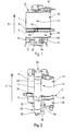
figure 1 is a side view of an embodiment of a heat exchanger according to the invention, -
figure 2 is a perspective view of the heat exchanger offigure 1 , -
figure 3 is a perspective view more precisely showing the connecting means of the heat exchanger of the preceding figures, -
figure 4 is partial view of the heat exchanger offigure 2 , viewed under another angle, -
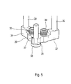
figure 5 is a perspective view showing a part of the connecting means offigure 3 . - According to
figures 1 and 2 , the invention relates to a heat exchanger between a first and a second fluid, especially a condenser for an air conditioning unit, more especially for automotive applications. - Said first fluid is for instance a refrigerant fluid, as the fluid known under R134a or R1234yf. The heat exchanger is configured to have it enter under gaseous phase and exit under liquid phase. The second fluid is for instance a cooling liquid as water added with some anti freeze like glycol. In other words, the cooling liquid may be a mixture of water and glycol.
- Said heat exchanger comprises a
first core 1 and optionally asecond core 5 stacked with said first core along a stacking direction D. In case of a condenser, said first core is especially configured to achieve a condensation of said refrigerant fluid and said second core to achieve a subcooling thereof. - Said
cores - Said
cores figure 4 ) stacked along said stacking direction to define said passages. In other words, a same plate defines a passage for the first fluid together with one of the adjoining plate and a passage for the second fluid with the other adjoining plate. - Said plates are for instance obtained by stamping a laminated plate of metal, especially aluminium and/or an aluminium alloy.
- Said
plates 3 may be of rectangular shape. As a consequence, said first andsecond cores lateral sides top sides bottom sides - Said
plates 3 comprise for instance a rising edge, defining with a bottom of said plate a volume in which said fluids flow. Said plates are provided, for instance, with four holes managed in the bottom of said plates, two of said holes being provided for the circulation of the first fluid and two other of said holes for the circulation of the second fluid. The holes for the circulation of the first fluid may be located along a first longitudinal side of said plate and the holes for the circulation of the other fluid along the other longitudinal side. - Said heat exchanger further comprise collecting means to have said first fluid flowing from one of said passage for the first to the next passage for the first fluid and said second fluid flowing from one of said passage for the second fluid to the next passage for the second fluid. Said collecting means are for instance constituted by two embossed portion of said plate bottom, each provided with one of said holes. More precisely, two of said holes are provided in a flat portion of said plates bottom and the two others are provided at the top of said embossed portion. When stacked, the two holes of the embossed portion of one said plate are in communication with the two holes provided in the flat portion of the bottom of one of the adjoining plate. As a result, one of said fluid flows in the passage provided between said two plates and the other of said fluid flows through said holes from one of the adjoining passage to the other of the adjoining passage.
- Said
plates 3 of both first and second cores may be of the same type, the differences between the two cores optionally being the number of plates which are used to constitute them and the location of the holes in the plates . It can also be seen that said plates are stacked from bottom to top in saidfirst core 1 and from top to bottom in saidsecond core 5. - As can be better seen on
figure 2 , said heat exchanger further comprises here areceiver 7 for said first fluid. Said receiver is connected upstream with saidfirst core 1 and optionally downstream with saidsecond core 5. In case of a condenser said receiver aims at separating the part of said refrigerant fluid potentially still in a gaseous phase from the part in liquid phase to let only said liquid phase part flow downstream. It may also aim at filtering and/or drying said refrigerant fluid. - Said
receiver 7 comprises for instance a cylindrical tank closed at its bothlongitudinal extremities receiver 7 into which said first fluid flows, when removed. - According to the invention, said heat exchanger further comprises connecting
means 9 to have said first fluid flowing between saidfirst core 1 and saidreceiver 7. Said connectingmeans 9 are here also configured to have said first fluid flowing between saidreceiver 7 and saidsecond core 5. - Said connecting
means 9 are further configured to support saidreceiver 7 in a shifted position relatively to saidfirst core 1 along said stacking direction and in parallel with a lateral side of saidfirst core 1, here said lateral side 1a. The invention thus increase the possibility of integration of said heat exchanger in its environment. It further gives the possibility to simultaneously attach the receiver to said first and/orsecond cores - More precisely, as can be better understood when considering
figures 2 and3 together, the first fluid enters thefirst core 1 trough aninlet flange 10 provided on a top end plate of saidfirst core 1 to flow between theplates 3 of saidfirst core 1. It then flows in saidreceiver 7 and from saidreceiver 7 to saidsecond core 5 throughrespective channels means 9. It finally flows between theplates 3 of saidsecond core 5 to exit through anoutlet flange 11 provided at a bottom end plate of saidsecond core 5. - Said connecting means are also advantageously configured to achieve a second fluid circulation between said first and said
second core second core 5 through aninlet flange 12 and thefirst core 1 through a secondfluid inlet pathway 15 provided in said connectingmeans 9, said second fluid inlet pathway communicating with said first and saidsecond cores plates 3 of bothcores second cores 5 through anoutlet flange 13 and saidfirst core 1 through a secondfluid outlet pathway 16 provided in said connectingmeans 9, said second fluid outlet pathway communicating with said first andsecond cores first core 1 and saidsecond core 5 may have independent circuits for said second fluid, said cores having then their own inlet and outlet flanges for said second fluid. - The connecting means 9 may be configured to support said
receiver 7 along any direction, especially said stacking direction as illustrated. Said connectingmeans 7 are here configured to support saidreceiver 7 along saidfirst core 1 and saidsecond core 5. Saidreceiver 7 may be higher than said first andsecond core means 9 along said stacking direction. In other words, one 8a of said receiver longitudinal extremities extend above saidfirst core 1 and/or the other 8b of its longitudinal extremities extend below saidsecond core 5. - In the illustrated embodiment, said connecting
means 9 are at least in part located between said first and saidsecond cores bottom end plate 3a of saidfirst core 1 and atop end plate 3b of saidsecond core 5. Saidend plates core 1, 5 (figure 4 ). - Said connecting
means 9 are here provided with connectingbrackets bracket 24 to a support. - Said connecting
means 9 comprise advantageously aframe 18 extending along said end plate of saidfirst core 1 and/or saidsecond core 5 and additional components to connect and support saidreceiver 7 along said lateral side 1a, saidlongitudinal extremity 8b of saidreceiver 7 being shifted from saidframe 18 along said stacking direction. - Said
frame 18 is here sandwiched between said first andsecond cores intermediate branch 19 connecting two longitudinal sides thereof. Said connectingbracket 24 to a support extends from saidframe 18. - Said
channels first portion 26 defined in saidframe 18 and asecond portion 28 in fluid communication with saidfirst portion 26. Said connectingmeans 9 comprisepipes 30 defining saidsecond portion 28. - As can be better seen on
figures 4 and5 , saidpipes 30 extend along saidreceiver 7. Saidpipes 30 support here afirst one 20 of said connecting brackets for saidreceiver 7, called base bracket, saidbase bracket 20 being connected to a longitudinal end of saidreceiver 7, here saidlongitudinal extremity 8b closed by a removable cap. - Said
base bracket 20 comprises for instance threebranches pipes 30 communicating with saidfirst core 1 and is provided with aninlet flange 33 communicating with saidreceiver 7. A second 34 of said branches is attached to a second of saidpipes 30 communicating with saidsecond core 5 and is provided with anoutlet flange 35 communicating with saidreceiver 7. The first fluid circulation from saidfirst core 1 to saidsecond core 5 through saidreceiver 7 is thus established. A third 36 of said branches is provided with atrough hole 37 trough which ascrew 50 attaches saidreceiver 7 to saidbase bracket 20 thanks to a threaded hole (not shown) provided in saidreceiver 7. - To enhance the positioning of said
receiver 7 relative to saidcores second one 22 of said connecting bracket for saidreceiver 7 extends laterally from saidframe 18. Said heat exchanger may also comprise a third connectingbracket 40 for said receiver 7 (figure 2 ). Said third connectingbracket 40 extends here from said top end plate of saidfirst core 1. - Said connecting
means 9 are advantageously configured to have saidreceiver 7 removably connected thereto. Said connectingbracket receiver 7 are thus only in contact with saidreceiver 7 to position it relative to said first and/orsecond cores receiver 7 is here attached to said connectingmeans 9 through saidscrew 50. - Said heat exchanger may further comprise other connecting brackets to a support, especially extending from said top end plate of said
first core 1 and/or said bottom end plate of said second core 2. - Said connecting
means 9 are for instance made of aluminium and/or aluminium alloy. Theframe 18,pipes 30 and connectingbrackets receiver 7 can be preassembled, for instance by flame brazing or welding. In another embodiment, they are brazed one shot with said first and/orsecond cores receiver 7 is attached to saidbase bracket 20 afterwards. - Said frame may be obtained either by casting or by extrusion process followed by machining operations. Said
channels
Claims (16)
- Heat exchanger between a first fluid and a second fluid, said heat exchanger comprising a first core (1) defining flow passages for said first fluid and said second fluid stacked alternatively along a stacking direction to have both fluids exchanging heat there between, said heat exchanger further comprising connecting means (9) to have said first fluid flowing between said first core (1) and a receiver (7) for said first fluid, said connecting means (9) being configured to support said receiver (7) in a shifted position relatively to said first core (1) along said stacking direction and in parallel with a side (1a) of said first core (1), said side (1a) being parallel to said stacking direction.
- Heat exchanger according to claim 1 in which said connecting means (9) are configured to support said receiver (7) along said stacking direction.
- Heat exchanger according to claim 1 or 2 further comprising a second core (5) stacked with said first core (1) along said stacking direction said connecting means (9) being at least partially located between said first and said second cores.
- Heat exchanger according to claim 3 according to which said connecting means (9) are configured to support said receiver (7) along said first core (1) and said second core (5).
- Heat exchanger according to claims 3 or 4 in which said connecting means (9) are configured to have said first fluid flowing between said receiver (7) and said second core (5).
- Heat exchanger according to any of claims 3 to 5 in which said connecting means (9) are provided with at least one channel (14a, 14b) to have said first fluid flowing from said first core (1) to said receiver (7) and/or from said receiver (7) to said second core (5).
- Heat exchanger according to any of claims 3 to 6 in which said connecting means (9) are provided with at least one connecting brackets (20, 22) for said receiver (7) and/or at least one connecting bracket (24) to a support.
- Heat exchanger according to claim 7 in which said connecting means (9) comprise a frame (18) extending along an end plate of said first core (1) and means to shift a connection of the receiver (7) from said frame (18) along said stacking direction.
- Heat exchanger according to claim 8 in which said frame (18) is sandwiched between said first and second cores (1, 5).
- Heat exchanger according to any of claim 8 or 9 in which said channels (14a, 14b) comprise a first portion (26) defined in said frame (18) and a second portion (28) in fluid communication with said first portion (26), said second portion (28) being defined by a pipe (30) of said connecting means (9).
- Heat exchanger according to claim 10 in which said pipes (30) extend along said receiver (7).
- Heat exchanger according to claim 11 in which said pipes (30) support a first one (20) of said connecting brackets for said receiver, called base bracket, said base bracket (20) being connected to a longitudinal end (8b) of said receiver (7).
- Heat exchanger according to claim 12 in which a second one (22) of said connecting brackets extend laterally from said frame (18).
- Heat exchanger according to any of claims 3 to 13 in which said connecting means (9) are one shot brazed with said first and/or second cores (1, 5).
- Heat exchanger according to any of claims 8 to 14 in which said frame (18) is one shot brazed with said first and/or said second cores (1, 5).
- Heat exchanger according to any preceding claims in which said connecting means (9) are configured to have said receiver (7) removably connected thereto.
Priority Applications (3)
| Application Number | Priority Date | Filing Date | Title |
|---|---|---|---|
| PL13461512.9T PL2784425T3 (en) | 2013-03-27 | 2013-03-27 | Heat exchanger, especially condenser |
| EP13461512.9A EP2784425B1 (en) | 2013-03-27 | 2013-03-27 | Heat exchanger, especially condenser |
| PCT/EP2014/055512 WO2014154546A1 (en) | 2013-03-27 | 2014-03-19 | Heat exchanger, especially condenser |
Applications Claiming Priority (1)
| Application Number | Priority Date | Filing Date | Title |
|---|---|---|---|
| EP13461512.9A EP2784425B1 (en) | 2013-03-27 | 2013-03-27 | Heat exchanger, especially condenser |
Publications (2)
| Publication Number | Publication Date |
|---|---|
| EP2784425A1 true EP2784425A1 (en) | 2014-10-01 |
| EP2784425B1 EP2784425B1 (en) | 2016-05-04 |
Family
ID=48047953
Family Applications (1)
| Application Number | Title | Priority Date | Filing Date |
|---|---|---|---|
| EP13461512.9A Active EP2784425B1 (en) | 2013-03-27 | 2013-03-27 | Heat exchanger, especially condenser |
Country Status (3)
| Country | Link |
|---|---|
| EP (1) | EP2784425B1 (en) |
| PL (1) | PL2784425T3 (en) |
| WO (1) | WO2014154546A1 (en) |
Cited By (2)
| Publication number | Priority date | Publication date | Assignee | Title |
|---|---|---|---|---|
| EP3973238A1 (en) * | 2019-05-21 | 2022-03-30 | Valeo Systemes Thermiques | Monoblock heat exchanger comprising at least two heat exchange blocks, each comprising a circulation path for a refrigerant and a circulation path for a heat transfer liquid |
| US11747096B2 (en) * | 2018-01-29 | 2023-09-05 | Valeo Autosystemy Sp. Z O.O. | Heat exchanging module having a housing comprising an inner frame and an outer frame |
Citations (4)
| Publication number | Priority date | Publication date | Assignee | Title |
|---|---|---|---|---|
| FR2923899A1 (en) * | 2007-11-20 | 2009-05-22 | Valeo Systemes Thermiques | CONDENSER FOR AIR CONDITIONING CIRCUIT WITH INTEGRATED BOTTLE |
| DE102010026507A1 (en) * | 2010-07-07 | 2012-01-12 | Behr Gmbh & Co. Kg | Refrigerant condenser module |
| DE102011007701A1 (en) * | 2011-04-19 | 2012-10-25 | Behr Gmbh & Co. Kg | Refrigerant condenser assembly |
| DE102011078136A1 (en) * | 2011-06-27 | 2012-12-27 | Behr Gmbh & Co. Kg | Refrigerant condenser module for condensation of cooling fluid for air conditioning apparatus to cool and/or heat inner space of motor car, has interstice provided between bases, and refrigerant transition channels arranged in interstice |
-
2013
- 2013-03-27 EP EP13461512.9A patent/EP2784425B1/en active Active
- 2013-03-27 PL PL13461512.9T patent/PL2784425T3/en unknown
-
2014
- 2014-03-19 WO PCT/EP2014/055512 patent/WO2014154546A1/en not_active Ceased
Patent Citations (4)
| Publication number | Priority date | Publication date | Assignee | Title |
|---|---|---|---|---|
| FR2923899A1 (en) * | 2007-11-20 | 2009-05-22 | Valeo Systemes Thermiques | CONDENSER FOR AIR CONDITIONING CIRCUIT WITH INTEGRATED BOTTLE |
| DE102010026507A1 (en) * | 2010-07-07 | 2012-01-12 | Behr Gmbh & Co. Kg | Refrigerant condenser module |
| DE102011007701A1 (en) * | 2011-04-19 | 2012-10-25 | Behr Gmbh & Co. Kg | Refrigerant condenser assembly |
| DE102011078136A1 (en) * | 2011-06-27 | 2012-12-27 | Behr Gmbh & Co. Kg | Refrigerant condenser module for condensation of cooling fluid for air conditioning apparatus to cool and/or heat inner space of motor car, has interstice provided between bases, and refrigerant transition channels arranged in interstice |
Cited By (4)
| Publication number | Priority date | Publication date | Assignee | Title |
|---|---|---|---|---|
| US11747096B2 (en) * | 2018-01-29 | 2023-09-05 | Valeo Autosystemy Sp. Z O.O. | Heat exchanging module having a housing comprising an inner frame and an outer frame |
| EP3973238A1 (en) * | 2019-05-21 | 2022-03-30 | Valeo Systemes Thermiques | Monoblock heat exchanger comprising at least two heat exchange blocks, each comprising a circulation path for a refrigerant and a circulation path for a heat transfer liquid |
| US12172489B2 (en) | 2019-05-21 | 2024-12-24 | Valeo Systemes Thermiques | Monoblock heat exchanger comprising at least two heat exchange blocks, each comprising a circulation path for a refrigerant and a circulation path for a heat transfer liquid |
| EP3973238B1 (en) * | 2019-05-21 | 2025-10-22 | Valeo Systemes Thermiques | Monoblock heat exchanger comprising at least two heat exchange blocks, each comprising a circulation path for a refrigerant and a circulation path for a heat transfer liquid |
Also Published As
| Publication number | Publication date |
|---|---|
| PL2784425T3 (en) | 2016-11-30 |
| WO2014154546A1 (en) | 2014-10-02 |
| EP2784425B1 (en) | 2016-05-04 |
Similar Documents
| Publication | Publication Date | Title |
|---|---|---|
| CN102639953B (en) | There is the car condenser strengthening integrated level | |
| US9927158B2 (en) | Refrigeration system with integrated core structure | |
| EP2927631B1 (en) | Heat exchanger, especially a condenser | |
| CN204648765U (en) | Condenser | |
| CN104995474B (en) | Condenser with refrigerant supply for air conditioning circuits | |
| US20170122669A1 (en) | Stacked heat exchanger | |
| US20110056667A1 (en) | Integrated multi-circuit microchannel heat exchanger | |
| EP2998676A1 (en) | Heat exchanger, in particular a condenser | |
| US10337808B2 (en) | Condenser | |
| JP4358981B2 (en) | Air conditioning condenser | |
| WO2015045105A1 (en) | Heat exchanger and air conditioner using same | |
| CN102192622B (en) | Condenser | |
| JP4047891B2 (en) | Heat exchanger | |
| EP2784413A1 (en) | Heat exchanger, especially condenser | |
| EP2784425B1 (en) | Heat exchanger, especially condenser | |
| US20220136785A1 (en) | Heat exchanger | |
| JP2008267753A (en) | Heat exchanger | |
| JP2007078292A (en) | Heat exchanger and double heat exchanger | |
| US20070251678A1 (en) | Heat exchanger and fitting | |
| JP5514611B2 (en) | Heat exchanger and manufacturing method thereof | |
| JP2018200132A (en) | Condenser | |
| JP5525805B2 (en) | Heat exchanger | |
| KR20240095873A (en) | Heat Exchanger | |
| JP2019027685A (en) | Capacitor | |
| JP5352275B2 (en) | Connection device for heat exchanger |
Legal Events
| Date | Code | Title | Description |
|---|---|---|---|
| 17P | Request for examination filed |
Effective date: 20130327 |
|
| AK | Designated contracting states |
Kind code of ref document: A1 Designated state(s): AL AT BE BG CH CY CZ DE DK EE ES FI FR GB GR HR HU IE IS IT LI LT LU LV MC MK MT NL NO PL PT RO RS SE SI SK SM TR |
|
| AX | Request for extension of the european patent |
Extension state: BA ME |
|
| PUAI | Public reference made under article 153(3) epc to a published international application that has entered the european phase |
Free format text: ORIGINAL CODE: 0009012 |
|
| R17P | Request for examination filed (corrected) |
Effective date: 20150401 |
|
| RBV | Designated contracting states (corrected) |
Designated state(s): AL AT BE BG CH CY CZ DE DK EE ES FI FR GB GR HR HU IE IS IT LI LT LU LV MC MK MT NL NO PL PT RO RS SE SI SK SM TR |
|
| GRAP | Despatch of communication of intention to grant a patent |
Free format text: ORIGINAL CODE: EPIDOSNIGR1 |
|
| INTG | Intention to grant announced |
Effective date: 20151123 |
|
| GRAS | Grant fee paid |
Free format text: ORIGINAL CODE: EPIDOSNIGR3 |
|
| GRAA | (expected) grant |
Free format text: ORIGINAL CODE: 0009210 |
|
| AK | Designated contracting states |
Kind code of ref document: B1 Designated state(s): AL AT BE BG CH CY CZ DE DK EE ES FI FR GB GR HR HU IE IS IT LI LT LU LV MC MK MT NL NO PL PT RO RS SE SI SK SM TR |
|
| REG | Reference to a national code |
Ref country code: GB Ref legal event code: FG4D |
|
| REG | Reference to a national code |
Ref country code: CH Ref legal event code: EP |
|
| REG | Reference to a national code |
Ref country code: AT Ref legal event code: REF Ref document number: 797298 Country of ref document: AT Kind code of ref document: T Effective date: 20160515 |
|
| REG | Reference to a national code |
Ref country code: IE Ref legal event code: FG4D |
|
| REG | Reference to a national code |
Ref country code: DE Ref legal event code: R096 Ref document number: 602013007249 Country of ref document: DE |
|
| REG | Reference to a national code |
Ref country code: NL Ref legal event code: MP Effective date: 20160504 |
|
| REG | Reference to a national code |
Ref country code: LT Ref legal event code: MG4D |
|
| PG25 | Lapsed in a contracting state [announced via postgrant information from national office to epo] |
Ref country code: FI Free format text: LAPSE BECAUSE OF FAILURE TO SUBMIT A TRANSLATION OF THE DESCRIPTION OR TO PAY THE FEE WITHIN THE PRESCRIBED TIME-LIMIT Effective date: 20160504 Ref country code: NO Free format text: LAPSE BECAUSE OF FAILURE TO SUBMIT A TRANSLATION OF THE DESCRIPTION OR TO PAY THE FEE WITHIN THE PRESCRIBED TIME-LIMIT Effective date: 20160804 Ref country code: LT Free format text: LAPSE BECAUSE OF FAILURE TO SUBMIT A TRANSLATION OF THE DESCRIPTION OR TO PAY THE FEE WITHIN THE PRESCRIBED TIME-LIMIT Effective date: 20160504 Ref country code: NL Free format text: LAPSE BECAUSE OF FAILURE TO SUBMIT A TRANSLATION OF THE DESCRIPTION OR TO PAY THE FEE WITHIN THE PRESCRIBED TIME-LIMIT Effective date: 20160504 |
|
| REG | Reference to a national code |
Ref country code: AT Ref legal event code: MK05 Ref document number: 797298 Country of ref document: AT Kind code of ref document: T Effective date: 20160504 |
|
| PG25 | Lapsed in a contracting state [announced via postgrant information from national office to epo] |
Ref country code: LV Free format text: LAPSE BECAUSE OF FAILURE TO SUBMIT A TRANSLATION OF THE DESCRIPTION OR TO PAY THE FEE WITHIN THE PRESCRIBED TIME-LIMIT Effective date: 20160504 Ref country code: SE Free format text: LAPSE BECAUSE OF FAILURE TO SUBMIT A TRANSLATION OF THE DESCRIPTION OR TO PAY THE FEE WITHIN THE PRESCRIBED TIME-LIMIT Effective date: 20160504 Ref country code: GR Free format text: LAPSE BECAUSE OF FAILURE TO SUBMIT A TRANSLATION OF THE DESCRIPTION OR TO PAY THE FEE WITHIN THE PRESCRIBED TIME-LIMIT Effective date: 20160805 Ref country code: RS Free format text: LAPSE BECAUSE OF FAILURE TO SUBMIT A TRANSLATION OF THE DESCRIPTION OR TO PAY THE FEE WITHIN THE PRESCRIBED TIME-LIMIT Effective date: 20160504 Ref country code: PT Free format text: LAPSE BECAUSE OF FAILURE TO SUBMIT A TRANSLATION OF THE DESCRIPTION OR TO PAY THE FEE WITHIN THE PRESCRIBED TIME-LIMIT Effective date: 20160905 Ref country code: ES Free format text: LAPSE BECAUSE OF FAILURE TO SUBMIT A TRANSLATION OF THE DESCRIPTION OR TO PAY THE FEE WITHIN THE PRESCRIBED TIME-LIMIT Effective date: 20160504 Ref country code: HR Free format text: LAPSE BECAUSE OF FAILURE TO SUBMIT A TRANSLATION OF THE DESCRIPTION OR TO PAY THE FEE WITHIN THE PRESCRIBED TIME-LIMIT Effective date: 20160504 |
|
| PG25 | Lapsed in a contracting state [announced via postgrant information from national office to epo] |
Ref country code: IT Free format text: LAPSE BECAUSE OF FAILURE TO SUBMIT A TRANSLATION OF THE DESCRIPTION OR TO PAY THE FEE WITHIN THE PRESCRIBED TIME-LIMIT Effective date: 20160504 |
|
| PG25 | Lapsed in a contracting state [announced via postgrant information from national office to epo] |
Ref country code: EE Free format text: LAPSE BECAUSE OF FAILURE TO SUBMIT A TRANSLATION OF THE DESCRIPTION OR TO PAY THE FEE WITHIN THE PRESCRIBED TIME-LIMIT Effective date: 20160504 Ref country code: SK Free format text: LAPSE BECAUSE OF FAILURE TO SUBMIT A TRANSLATION OF THE DESCRIPTION OR TO PAY THE FEE WITHIN THE PRESCRIBED TIME-LIMIT Effective date: 20160504 Ref country code: DK Free format text: LAPSE BECAUSE OF FAILURE TO SUBMIT A TRANSLATION OF THE DESCRIPTION OR TO PAY THE FEE WITHIN THE PRESCRIBED TIME-LIMIT Effective date: 20160504 Ref country code: RO Free format text: LAPSE BECAUSE OF FAILURE TO SUBMIT A TRANSLATION OF THE DESCRIPTION OR TO PAY THE FEE WITHIN THE PRESCRIBED TIME-LIMIT Effective date: 20160504 |
|
| REG | Reference to a national code |
Ref country code: DE Ref legal event code: R097 Ref document number: 602013007249 Country of ref document: DE |
|
| PG25 | Lapsed in a contracting state [announced via postgrant information from national office to epo] |
Ref country code: BE Free format text: LAPSE BECAUSE OF FAILURE TO SUBMIT A TRANSLATION OF THE DESCRIPTION OR TO PAY THE FEE WITHIN THE PRESCRIBED TIME-LIMIT Effective date: 20160504 Ref country code: SM Free format text: LAPSE BECAUSE OF FAILURE TO SUBMIT A TRANSLATION OF THE DESCRIPTION OR TO PAY THE FEE WITHIN THE PRESCRIBED TIME-LIMIT Effective date: 20160504 Ref country code: AT Free format text: LAPSE BECAUSE OF FAILURE TO SUBMIT A TRANSLATION OF THE DESCRIPTION OR TO PAY THE FEE WITHIN THE PRESCRIBED TIME-LIMIT Effective date: 20160504 |
|
| PLBE | No opposition filed within time limit |
Free format text: ORIGINAL CODE: 0009261 |
|
| STAA | Information on the status of an ep patent application or granted ep patent |
Free format text: STATUS: NO OPPOSITION FILED WITHIN TIME LIMIT |
|
| REG | Reference to a national code |
Ref country code: FR Ref legal event code: PLFP Year of fee payment: 5 |
|
| 26N | No opposition filed |
Effective date: 20170207 |
|
| PG25 | Lapsed in a contracting state [announced via postgrant information from national office to epo] |
Ref country code: SI Free format text: LAPSE BECAUSE OF FAILURE TO SUBMIT A TRANSLATION OF THE DESCRIPTION OR TO PAY THE FEE WITHIN THE PRESCRIBED TIME-LIMIT Effective date: 20160504 |
|
| REG | Reference to a national code |
Ref country code: CH Ref legal event code: PL |
|
| GBPC | Gb: european patent ceased through non-payment of renewal fee |
Effective date: 20170327 |
|
| PG25 | Lapsed in a contracting state [announced via postgrant information from national office to epo] |
Ref country code: MC Free format text: LAPSE BECAUSE OF FAILURE TO SUBMIT A TRANSLATION OF THE DESCRIPTION OR TO PAY THE FEE WITHIN THE PRESCRIBED TIME-LIMIT Effective date: 20160504 |
|
| REG | Reference to a national code |
Ref country code: IE Ref legal event code: MM4A |
|
| PG25 | Lapsed in a contracting state [announced via postgrant information from national office to epo] |
Ref country code: LU Free format text: LAPSE BECAUSE OF NON-PAYMENT OF DUE FEES Effective date: 20170327 |
|
| PG25 | Lapsed in a contracting state [announced via postgrant information from national office to epo] |
Ref country code: LI Free format text: LAPSE BECAUSE OF NON-PAYMENT OF DUE FEES Effective date: 20170331 Ref country code: GB Free format text: LAPSE BECAUSE OF NON-PAYMENT OF DUE FEES Effective date: 20170327 Ref country code: CH Free format text: LAPSE BECAUSE OF NON-PAYMENT OF DUE FEES Effective date: 20170331 Ref country code: IE Free format text: LAPSE BECAUSE OF NON-PAYMENT OF DUE FEES Effective date: 20170327 |
|
| REG | Reference to a national code |
Ref country code: FR Ref legal event code: PLFP Year of fee payment: 6 |
|
| PG25 | Lapsed in a contracting state [announced via postgrant information from national office to epo] |
Ref country code: MT Free format text: LAPSE BECAUSE OF NON-PAYMENT OF DUE FEES Effective date: 20170327 |
|
| PG25 | Lapsed in a contracting state [announced via postgrant information from national office to epo] |
Ref country code: AL Free format text: LAPSE BECAUSE OF FAILURE TO SUBMIT A TRANSLATION OF THE DESCRIPTION OR TO PAY THE FEE WITHIN THE PRESCRIBED TIME-LIMIT Effective date: 20160504 |
|
| PG25 | Lapsed in a contracting state [announced via postgrant information from national office to epo] |
Ref country code: HU Free format text: LAPSE BECAUSE OF FAILURE TO SUBMIT A TRANSLATION OF THE DESCRIPTION OR TO PAY THE FEE WITHIN THE PRESCRIBED TIME-LIMIT; INVALID AB INITIO Effective date: 20130327 |
|
| PG25 | Lapsed in a contracting state [announced via postgrant information from national office to epo] |
Ref country code: BG Free format text: LAPSE BECAUSE OF FAILURE TO SUBMIT A TRANSLATION OF THE DESCRIPTION OR TO PAY THE FEE WITHIN THE PRESCRIBED TIME-LIMIT Effective date: 20160504 |
|
| PG25 | Lapsed in a contracting state [announced via postgrant information from national office to epo] |
Ref country code: CY Free format text: LAPSE BECAUSE OF FAILURE TO SUBMIT A TRANSLATION OF THE DESCRIPTION OR TO PAY THE FEE WITHIN THE PRESCRIBED TIME-LIMIT Effective date: 20160504 |
|
| PG25 | Lapsed in a contracting state [announced via postgrant information from national office to epo] |
Ref country code: MK Free format text: LAPSE BECAUSE OF FAILURE TO SUBMIT A TRANSLATION OF THE DESCRIPTION OR TO PAY THE FEE WITHIN THE PRESCRIBED TIME-LIMIT Effective date: 20160504 |
|
| PG25 | Lapsed in a contracting state [announced via postgrant information from national office to epo] |
Ref country code: IS Free format text: LAPSE BECAUSE OF FAILURE TO SUBMIT A TRANSLATION OF THE DESCRIPTION OR TO PAY THE FEE WITHIN THE PRESCRIBED TIME-LIMIT Effective date: 20160904 |
|
| PGFP | Annual fee paid to national office [announced via postgrant information from national office to epo] |
Ref country code: CZ Payment date: 20210219 Year of fee payment: 9 |
|
| PGFP | Annual fee paid to national office [announced via postgrant information from national office to epo] |
Ref country code: TR Payment date: 20210316 Year of fee payment: 9 Ref country code: PL Payment date: 20210305 Year of fee payment: 9 |
|
| PG25 | Lapsed in a contracting state [announced via postgrant information from national office to epo] |
Ref country code: CZ Free format text: LAPSE BECAUSE OF NON-PAYMENT OF DUE FEES Effective date: 20220327 |
|
| P01 | Opt-out of the competence of the unified patent court (upc) registered |
Effective date: 20230528 |
|
| PG25 | Lapsed in a contracting state [announced via postgrant information from national office to epo] |
Ref country code: PL Free format text: LAPSE BECAUSE OF NON-PAYMENT OF DUE FEES Effective date: 20220327 |
|
| PG25 | Lapsed in a contracting state [announced via postgrant information from national office to epo] |
Ref country code: TR Free format text: LAPSE BECAUSE OF NON-PAYMENT OF DUE FEES Effective date: 20220327 |
|
| PGFP | Annual fee paid to national office [announced via postgrant information from national office to epo] |
Ref country code: FR Payment date: 20250331 Year of fee payment: 13 |
|
| PGFP | Annual fee paid to national office [announced via postgrant information from national office to epo] |
Ref country code: DE Payment date: 20260313 Year of fee payment: 14 |