EP2784323B1 - Pump - Google Patents
Pump Download PDFInfo
- Publication number
- EP2784323B1 EP2784323B1 EP14161917.1A EP14161917A EP2784323B1 EP 2784323 B1 EP2784323 B1 EP 2784323B1 EP 14161917 A EP14161917 A EP 14161917A EP 2784323 B1 EP2784323 B1 EP 2784323B1
- Authority
- EP
- European Patent Office
- Prior art keywords
- discharge
- side groove
- rotor
- internal teeth
- outer rotor
- Prior art date
- Legal status (The legal status is an assumption and is not a legal conclusion. Google has not performed a legal analysis and makes no representation as to the accuracy of the status listed.)
- Active
Links
- 230000003247 decreasing effect Effects 0.000 description 6
- 230000015572 biosynthetic process Effects 0.000 description 5
- 230000037431 insertion Effects 0.000 description 3
- 238000003780 insertion Methods 0.000 description 3
- 230000000052 comparative effect Effects 0.000 description 2
- 230000005540 biological transmission Effects 0.000 description 1
- 230000001419 dependent effect Effects 0.000 description 1
- 230000002708 enhancing effect Effects 0.000 description 1
- 239000012530 fluid Substances 0.000 description 1
- 230000002093 peripheral effect Effects 0.000 description 1
Images


Classifications
-
- F—MECHANICAL ENGINEERING; LIGHTING; HEATING; WEAPONS; BLASTING
- F04—POSITIVE - DISPLACEMENT MACHINES FOR LIQUIDS; PUMPS FOR LIQUIDS OR ELASTIC FLUIDS
- F04C—ROTARY-PISTON, OR OSCILLATING-PISTON, POSITIVE-DISPLACEMENT MACHINES FOR LIQUIDS; ROTARY-PISTON, OR OSCILLATING-PISTON, POSITIVE-DISPLACEMENT PUMPS
- F04C2/00—Rotary-piston machines or pumps
- F04C2/08—Rotary-piston machines or pumps of intermeshing-engagement type, i.e. with engagement of co-operating members similar to that of toothed gearing
- F04C2/10—Rotary-piston machines or pumps of intermeshing-engagement type, i.e. with engagement of co-operating members similar to that of toothed gearing of internal-axis type with the outer member having more teeth or tooth-equivalents, e.g. rollers, than the inner member
- F04C2/103—Rotary-piston machines or pumps of intermeshing-engagement type, i.e. with engagement of co-operating members similar to that of toothed gearing of internal-axis type with the outer member having more teeth or tooth-equivalents, e.g. rollers, than the inner member one member having simultaneously a rotational movement about its own axis and an orbital movement
-
- F—MECHANICAL ENGINEERING; LIGHTING; HEATING; WEAPONS; BLASTING
- F04—POSITIVE - DISPLACEMENT MACHINES FOR LIQUIDS; PUMPS FOR LIQUIDS OR ELASTIC FLUIDS
- F04C—ROTARY-PISTON, OR OSCILLATING-PISTON, POSITIVE-DISPLACEMENT MACHINES FOR LIQUIDS; ROTARY-PISTON, OR OSCILLATING-PISTON, POSITIVE-DISPLACEMENT PUMPS
- F04C2/00—Rotary-piston machines or pumps
- F04C2/08—Rotary-piston machines or pumps of intermeshing-engagement type, i.e. with engagement of co-operating members similar to that of toothed gearing
- F04C2/10—Rotary-piston machines or pumps of intermeshing-engagement type, i.e. with engagement of co-operating members similar to that of toothed gearing of internal-axis type with the outer member having more teeth or tooth-equivalents, e.g. rollers, than the inner member
- F04C2/102—Rotary-piston machines or pumps of intermeshing-engagement type, i.e. with engagement of co-operating members similar to that of toothed gearing of internal-axis type with the outer member having more teeth or tooth-equivalents, e.g. rollers, than the inner member the two members rotating simultaneously around their respective axes
-
- F—MECHANICAL ENGINEERING; LIGHTING; HEATING; WEAPONS; BLASTING
- F04—POSITIVE - DISPLACEMENT MACHINES FOR LIQUIDS; PUMPS FOR LIQUIDS OR ELASTIC FLUIDS
- F04C—ROTARY-PISTON, OR OSCILLATING-PISTON, POSITIVE-DISPLACEMENT MACHINES FOR LIQUIDS; ROTARY-PISTON, OR OSCILLATING-PISTON, POSITIVE-DISPLACEMENT PUMPS
- F04C2250/00—Geometry
- F04C2250/10—Geometry of the inlet or outlet
- F04C2250/102—Geometry of the inlet or outlet of the outlet
-
- F—MECHANICAL ENGINEERING; LIGHTING; HEATING; WEAPONS; BLASTING
- F04—POSITIVE - DISPLACEMENT MACHINES FOR LIQUIDS; PUMPS FOR LIQUIDS OR ELASTIC FLUIDS
- F04C—ROTARY-PISTON, OR OSCILLATING-PISTON, POSITIVE-DISPLACEMENT MACHINES FOR LIQUIDS; ROTARY-PISTON, OR OSCILLATING-PISTON, POSITIVE-DISPLACEMENT PUMPS
- F04C2270/00—Control; Monitoring or safety arrangements
- F04C2270/16—Wear
Definitions
- the invention relates to a pump that sucks in and discharges fluid such as oil according to the preamble of claim 1, the features of which are known from document EP 2 261 508 A1 .
- an oil pump used in an automobile includes an outer rotor, an inner rotor and a housing having a pump chamber in which the outer rotor and the inner rotor are rotatably accommodated.
- Internal teeth formed in a trochoidal curve shape are formed on the inner periphery of the outer rotor.
- External teeth formed in a trochoidal curve shape are formed on the outer periphery of the inner rotor, and meshed with the internal teeth of the outer rotor.
- the inner rotor is rotated by a motor.
- the housing has a suction passage and a discharge passage that are communicated with the pump chamber.
- the pump chamber of the housing has a bottom portion in which a suction-side groove communicated with the suction passage and a discharge-side groove communicated with the discharge passage are formed as recesses.
- the suction-side groove and the discharge-side groove are apart from each other and extend along the circumferential direction of the bottom portion of the pump chamber.
- an inner edge of a discharge-side groove is located radially outward of the bottom lands of external teeth of an inner rotor. This is because, if the length of contact between the inner rotor and a bottom portion of a pump chamber in the radial direction is set longer, it is possible to suppress leakage of the oil from spaces defined between the external teeth and the internal teeth into a side clearance that is a clearance between the bottom portion of the pump chamber and the inner rotor, thereby enhancing the efficiency of the pump.
- the tooth tips of the internal teeth may be overlapped with the inner edge of the discharge-side groove.
- the spaces defined between the external teeth and the internal teeth are turned into closed spaces that are not opened into the discharge-side groove.
- the oil in the closed spaces flows at a high flow rate into spaces between the internal teeth and the external teeth, which are opened into the discharge-side groove. This raises a possibility that the inner edge of the discharge-side groove will be damaged.
- the object of the invention is to provide a pump configured such that damage to an inner edge of a discharge-side groove is reduced.
- An aspect of the invention relates to a pump including: a housing in which a pump chamber that is a columnar space is formed, the pump chamber being provided with a suction-side groove and a discharge-side groove that are formed as recesses; an outer rotor rotatably disposed in the pump chamber and having internal teeth on an inner periphery of the outer rotor; and an inner rotor disposed radially inward of the internal teeth of the outer rotor, and having external teeth formed on an outer periphery of the inner rotor and meshed with the internal teeth of the outer rotor.
- a portion of an inner edge of the discharge-side groove is located radially inward of a locus of tooth tips of the internal teeth of the outer rotor, the portion being located in a second half region of the discharge-side groove in a rotational direction of the inner rotor and the outer rotor.
- a pump 10 includes a housing 11, an inner rotor 12, an outer rotor 13 and a seal member 14.
- rotational direction (indicated by an arrow in FIG. 2 ) of the inner rotor 12 and the outer rotor 13 will be simply referred to as "rotational direction”.
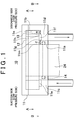
- the housing 11 has a block shape, and a pump chamber 11b that is a flat columnar space is formed in the housing 11. As illustrated in FIG. 1 , an insertion hole 11a communicated with the pump chamber 11b is formed at the center of a bottom portion of the housing 11. A rotary shaft 24 is passed through the insertion hole 11 a. The seal member 14 having a ring shape is fitted in the insertion hole 11 a. The seal member 14 contacts the rotary shaft 24 over the entire circumference thereof to seal a gap between the housing 11 and the rotary shaft 24. Note that the rotary shaft 24 is rotated by an engine, a transmission, a motor, or the like (none of which is illustrated).
- the outer rotor 13 is rotatably disposed in the pump chamber 11b.
- the outer rotor 13 has a circular sectional shape and a short cylinder shape.
- Internal teeth 13a are formed on the inner periphery of the outer rotor 13 so as to define spaces.
- the inner rotor 12 is rotatably disposed at a position radially inward of the internal teeth 13a.
- the inner rotor 12 has a ring shape, and external teeth 12a are formed at an outer peripheral edge of the inner rotor 12.
- the internal teeth 13a and the external teeth 12a are defined by a plurality of trochoidal curves.
- the number of the external teeth 12a is smaller than that of the internal teeth 13a.
- the internal teeth 13a and the external teeth 12a are meshed with each other.
- the center of rotation of the outer rotor 13 is coincident with the center of the columnar pump chamber 11b. As illustrated in FIG. 4 , the center of rotation of the inner rotor 12 is offset from the center of rotation of the outer rotor 13.
- the inner rotor 12 is concentrically fitted on the rotary shaft 24, and the inner rotor 12 and the rotary shaft 24 rotate together with each other.
- a suction-side groove 11e and a discharge-side groove 11f that have a crescent shape are formed as recesses in at least one of opposed faces that define the columnar space of the pump chamber 11b.
- the suction-side groove 11e and the discharge-side groove 11f are formed as recesses in a bottom portion of the pump chamber 11b.
- the suction-side groove 11e and the discharge-side groove 11f are located at predetermined intervals and extend along the circumferential direction of the bottom portion of the pump chamber 11b.
- the suction-side groove 11e and the discharge-side groove 11f are opposed to each other in the bottom portion of the pump chamber 11b.
- suction-side groove 11e and the discharge-side groove 11f are formed on a locus on which the spaces defined between the external teeth 12a and the internal teeth 13a move.
- suction side the side of the pump chamber 11b, in which the suction-side groove 11e is formed
- discharge side the side of the pump chamber 11b, in which the discharge-side groove 11f is formed
- an inner edge 11g of the discharge-side groove 11f is located radially inward of a locus (with a radius a) of tooth tips 13b of the internal teeth 13a of the outer rotor 13, at least over a second half region 11x of the discharge-side groove 11f in the rotational direction of the inner rotor 12 and the outer rotor 13.
- An outer edge 11h of the discharge-side groove 11f is located radially outward of a locus (with a radius b) of the tooth tips 12b of the external teeth 12a of the inner rotor 12, at least over the second half region 11x of the discharge-side groove 11f.
- the second half region 11x of the discharge-side groove 11f is a region extending from a trailing end 11j of the discharge-side groove 11f to a position apart from the trailing end 11j in a direction toward a leading end 11k of the discharge-side groove 11f by a predetermined distance, as illustrated in FIG. 3 .
- closed spaces 91, 92 may be formed in the second half region 11x.
- the trailing end 11j of the discharge-side groove 11f is located at a position at which the spaces defined between the external teeth 12a and the internal teeth 13a finish passing by the discharge-side groove 11f and exit from the discharge-side groove 11f.
- the leading end 11k of the discharge-side groove 11f is located at a position at which the spaces defined between the external teeth 12a and the internal teeth 13a enter the first the discharge-side groove 11f.
- the inner edge 11g of the discharge-side groove 11f is located radially inward of the locus (with the radius a) of the tooth tips 13b of the internal teeth 13a of the outer rotor 13, over a region from the leading end 11k to the trailing end 11j of the discharge-side groove 11f.
- the outer edge 11h of the discharge-side groove 11f is located radially outward of the locus (with the radius b) of the tooth tips 12b of the external teeth 12a of the inner rotor 12, over the region from the leading end 11k to the trailing end 11j of the discharge-side groove 11f.
- a suction passage 11c is formed in the housing 11 and is communicated with a bottom portion of the suction-side groove 11e and thus communicated with the pump chamber 11b.
- the position at which the suction passage 11c is communicated with the bottom portion of the suction-side groove 11e is coincident with a leading end of the suction-side groove 11e, at which the spaces defined between the external teeth 12a and the external teeth 13a enter the suction passage 11c.
- a discharge passage 11d is formed in the housing 11 and is communicated with a bottom portion of the discharge-side groove 11f and thus communicated with the pump chamber 11b.
- the position at which the discharge passage 11d is communicated with the bottom portion of the discharge-side groove 11f is coincident with the trailing end 11j of the discharge-side groove 11f.
- the inner rotor 12 rotates and thus the outer rotor 13 engaged at the internal teeth 13a with the external teeth 12a of the inner rotor 12 also rotates.
- the spaces defined between the external teeth 12a and the internal teeth 13a pass by the suction passage 11c, the suction-side groove 11e, the discharge-side groove 11f and the discharge passage 11d in this order, and thus the oil is delivered from the suction passage 11c into the discharge passage 11d.
- the pressure of the oil is higher on the discharge side (high pressure side) of the pump chamber 11b than on the suction side (low pressure side) of the pump chamber 11b during the operation of the pump 10.
- the inner side clearance 11m is a clearance defined between a bottom face of the pump chamber 11b of the housing 11 and a side face of the inner rotor 12.
- the outer side clearance 11n is a clearance defined between the bottom face of the pump chamber 11b of the housing 11 and a side face of the outer rotor 13.
- the inner edge 11g of the discharge-side groove 11f is located radially outward of the locus (with a radius c) of bottom lands 12c of the external teeth 12a of the inner rotor 12.
- a length f of contact between the inner rotor 12 and the bottom portion of the pump chamber 11b in the radial direction becomes longer and thus leakage of the oil from the spaces defined between the external teeth 12a and the internal teeth 13a into the inner side clearance 11m is suppressed.
- the outer edge 11h of the discharge-side groove 11f is located radially inward of the locus (with a radius d) of bottom lands 13c of the internal teeth 13a of the outer rotor 13.
- a length e of contact between the outer rotor 13 and the bottom portion of the pump chamber 11b in the radial direction becomes longer and thus leakage of the oil from the spaces defined between the external teeth 12a and the internal teeth 13a into the outer side clearance 11n is suppressed.
- the spaces defined between the external teeth 12a of the inner rotor 12 and the internal teeth 13a of the outer rotor 13 become narrower as they are advanced from the leading end 11k to the trailing end 11j of the discharge-side groove 11f.
- the inner edge 11g of the discharge-side groove 11f is located radially outward of the locus (with the radius c) of the bottom lands 12c of the external teeth 12a of the inner rotor 12 and the outer edge 11h of the discharge-side groove 11f is located radially inward of the locus (with the radius d) of the bottom lands 13c of the internal teeth 13a of the outer rotor 13.
- the tooth tips 13b of the internal teeth 13a may overlap with the inner edge 11g of the discharge-side groove 11f, in the second half region of the discharge-side groove 11f.
- one of the spaces between the external teeth 12a and the internal teeth 13a is turned into the closed space 91 that is not opened to the discharge-side groove 11f.
- the tooth tips 12b of the external teeth 12a may overlap with the outer edge 11h of the discharge-side groove 11f, in the second half region 11x of the discharge-side groove 11f.
- one of the spaces between the external teeth 12a and the internal teeth 13a is turned into the closed space 92 that is not opened to the discharge-side groove 11f.
- the volumes of the closed spaces 91, 92 formed as described above are decreased as the inner rotor 12 and the outer rotor 13 rotate.
- the oil in the closed spaces 91, 92 flows at a high flow rate into the spaces that are defined between the external teeth 12a and the internal teeth 13a and that are opened into the discharge-side groove 11f (refer to (1) and (2) in FIG. 5 ).
- the external teeth 12a and the internal teeth 13a will be damaged.
- the formation of the closed space 91 is prevented even if the inner edge 11g of the discharge-side groove 11f is located radially inward of the locus of the bottom lands 12c of the external teeth 12a of the inner rotor 12.
- the inner edge 11g of the discharge-side groove 11f is located radially inward of the locus of the tooth tips 13b of the internal teeth 13a of the outer rotor 13.
- the formation of the closed space 92 is prevented even if the outer edge 11h of the discharge-side groove 11f is located radially outward of the locus of the bottom lands 13c of the internal teeth 13a of the outer rotor 13.
- the outer edge 11h of the discharge-side groove 11f is located radially outward of the locus of the tooth tips 12b of the external teeth 12a of the inner rotor 12.
- the invention may be implemented in an embodiment in which the inner edge 11g of the discharge-side groove 11f is located radially outward of the locus (with the radius c) of the bottom lands 12c of the external teeth 12a of the inner rotor 12 and is also located radially inward of the locus (with the radius a) of the tooth tips 13b of the internal teeth 13a of the outer rotor 13.
- the invention may be implemented in an embodiment in which the outer edge 11h of the discharge-side groove 11f is located radially inward of the locus (with the radius d) of the bottom lands 13c of the internal teeth 13a of the outer rotor 13 and is also located radially outward of the locus of the tooth tips 12b of the external teeth 12a of the inner rotor 12.
- the lengths f, e of contact between the inner and outer rotors 12, 13 and the bottom of the pump chamber 11b in the radial direction are set longer, and thus the formation of the closed spaces 91, 92 (refer to FIG. 5 ) is prevented while the leakage of the oil into the side clearances 11m, 11n is suppressed.
- the entirety of the inner edge 11g of the discharge-side groove 11f is located radially inward of the locus of the tooth tips 13b of the internal teeth 13a of the outer rotor 13.
- the invention may be implemented in an embodiment in which only a portion of the inner edge llg, the portion being in the second half region 11x of the discharge-side groove 11f, is partially located radially inward of the locus of the tooth tips 13b of the internal teeth 13a of the outer rotor 13, or in an embodiment in which only the portion of the inner edge 11g, the portion being in the second half region 11x of the discharge-side groove 11f, is entirely located radially inward of the locus of the tooth tips 13b of the internal teeth 13a of the outer rotor 13.
- the entirety of the outer edge 11h of the discharge-side groove 11f is located radially outward of the locus of the tooth tips 12b of the external teeth 12a of the inner rotor 12.
- the invention may be implemented in an embodiment in which only a portion of the outer edge 11h, the portion being in the second half region 11x of the discharge-side groove 11f, is partially located radially outward of the locus of the tooth tips 12b of the external teeth 12a of the inner rotor 12, or in an embodiment in which only the portion of the outer edge 11h, the portion being in the second half region 11x of the discharge-side groove 11f, is entirely located radially outward of the locus of the tooth tips 12b of the external teeth 12a of the inner rotor 12. In these embodiments, it is possible to reduce damage to a portion of the outer edge 11h of the discharge-side groove 11f, the portion being located radially outward of the locus of the tooth tips 12b of the external teeth 12a of the inner rotor 12.
- only one discharge-side groove 11f is formed in the bottom portion of the pump chamber 11b.
- the invention may be implemented in an embodiment in which two or more discharge-side grooves 11f are formed in the bottom portion of the pump chamber 11.
- a pump includes: a housing in which a pump chamber that is a columnar space is formed, the pump chamber being provided with a suction-side groove and a discharge-side groove that are formed as recesses; an outer rotor rotatably disposed in the pump chamber and having internal teeth on an inner periphery of the outer rotor; and an inner rotor disposed radially inward of the internal teeth of the outer rotor, and having external teeth formed on an outer periphery of the inner rotor and meshed with the internal teeth of the outer rotor.
- a portion of an inner edge of the discharge-side groove is located radially inward of a locus of tooth tips of the internal teeth of the outer rotor, the portion being located in a second half region of the discharge-side groove in a rotational direction of the inner rotor and the outer rotor.
Description
- The invention relates to a pump that sucks in and discharges fluid such as oil according to the preamble of
claim 1, the features of which are known fromdocument EP 2 261 508 A1 . - As described in document
JP 11-324938 A
and a housing having a pump chamber in which the outer rotor and the inner rotor are rotatably accommodated. Internal teeth formed in a trochoidal curve shape are formed on the inner periphery of the outer rotor. External teeth formed in a trochoidal curve shape are formed on the outer periphery of the inner rotor, and meshed with the internal teeth of the outer rotor. The inner rotor is rotated by a motor. - The housing has a suction passage and a discharge passage that are communicated with the pump chamber. The pump chamber of the housing has a bottom portion in which a suction-side groove communicated with the suction passage and a discharge-side groove communicated with the discharge passage are formed as recesses. The suction-side groove and the discharge-side groove are apart from each other and extend along the circumferential direction of the bottom portion of the pump chamber. In the oil pump configured as described above, the inner rotor and the outer rotor rotate while being meshed with each other. Thus, the oil sucked in through the suction passage is discharged through the discharge passage.
- In some conventional pumps, an inner edge of a discharge-side groove is located radially outward of the bottom lands of external teeth of an inner rotor. This is because, if the length of contact between the inner rotor and a bottom portion of a pump chamber in the radial direction is set longer, it is possible to suppress leakage of the oil from spaces defined between the external teeth and the internal teeth into a side clearance that is a clearance between the bottom portion of the pump chamber and the inner rotor, thereby enhancing the efficiency of the pump.
- If the inner edge of the discharge-side groove is located radially outward of the bottom lands of the external teeth of the inner rotor, the tooth tips of the internal teeth may be overlapped with the inner edge of the discharge-side groove. In this case, the spaces defined between the external teeth and the internal teeth are turned into closed spaces that are not opened into the discharge-side groove. When the volumes of the closed spaces are decreased as the inner rotor and the outer rotor rotate, the oil in the closed spaces flows at a high flow rate into spaces between the internal teeth and the external teeth, which are opened into the discharge-side groove. This raises a possibility that the inner edge of the discharge-side groove will be damaged.
- Document
EP 2 123 914A1 discloses another generic pump. - The object of the invention is to provide a pump configured such that damage to an inner edge of a discharge-side groove is reduced.
- The object of the invention is achieved by a pump according to
claim 1. Advantageous embodiments are carried out according to the dependent claims. - An aspect of the invention relates to a pump including: a housing in which a pump chamber that is a columnar space is formed, the pump chamber being provided with a suction-side groove and a discharge-side groove that are formed as recesses; an outer rotor rotatably disposed in the pump chamber and having internal teeth on an inner periphery of the outer rotor; and an inner rotor disposed radially inward of the internal teeth of the outer rotor, and having external teeth formed on an outer periphery of the inner rotor and meshed with the internal teeth of the outer rotor. A portion of an inner edge of the discharge-side groove is located radially inward of a locus of tooth tips of the internal teeth of the outer rotor, the portion being located in a second half region of the discharge-side groove in a rotational direction of the inner rotor and the outer rotor.
- The foregoing and further features and advantages of the invention will become apparent from the following description of example embodiments with reference to the accompanying drawings, wherein like numerals are used to represent like elements and wherein:
-
FIG. 1 is a side view of a pump; -
FIG. 2 is a sectional view of the pump taken along the line A-A inFIG. 1 , illustrating an inner rotor and an outer rotor; -
FIG. 3 is a sectional view of the pump taken along the line B-B inFIG. 1 , illustrating a bottom portion of a housing; -
FIG. 4 is an enlarged view of the pump inFIG. 3 ; and -
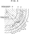
FIG. 5 is a view of a pump in a comparative example. - Hereinafter, an embodiment of the invention will be described with reference to the accompanying drawings. As illustrated in
FIG. 1 andFIG. 2 , apump 10 includes ahousing 11, aninner rotor 12, anouter rotor 13 and aseal member 14. In the following description, the rotational direction (indicated by an arrow inFIG. 2 ) of theinner rotor 12 and theouter rotor 13 will be simply referred to as "rotational direction". - The
housing 11 has a block shape, and apump chamber 11b that is a flat columnar space is formed in thehousing 11. As illustrated inFIG. 1 , aninsertion hole 11a communicated with thepump chamber 11b is formed at the center of a bottom portion of thehousing 11. Arotary shaft 24 is passed through theinsertion hole 11 a. Theseal member 14 having a ring shape is fitted in theinsertion hole 11 a. Theseal member 14 contacts therotary shaft 24 over the entire circumference thereof to seal a gap between thehousing 11 and therotary shaft 24. Note that therotary shaft 24 is rotated by an engine, a transmission, a motor, or the like (none of which is illustrated). - As illustrated in
FIG. 2 , theouter rotor 13 is rotatably disposed in thepump chamber 11b. Theouter rotor 13 has a circular sectional shape and a short cylinder shape.Internal teeth 13a are formed on the inner periphery of theouter rotor 13 so as to define spaces. Theinner rotor 12 is rotatably disposed at a position radially inward of theinternal teeth 13a. - The
inner rotor 12 has a ring shape, andexternal teeth 12a are formed at an outer peripheral edge of theinner rotor 12. Theinternal teeth 13a and theexternal teeth 12a are defined by a plurality of trochoidal curves. The number of theexternal teeth 12a is smaller than that of theinternal teeth 13a. Theinternal teeth 13a and theexternal teeth 12a are meshed with each other. The center of rotation of theouter rotor 13 is coincident with the center of thecolumnar pump chamber 11b. As illustrated inFIG. 4 , the center of rotation of theinner rotor 12 is offset from the center of rotation of theouter rotor 13. Theinner rotor 12 is concentrically fitted on therotary shaft 24, and theinner rotor 12 and therotary shaft 24 rotate together with each other. - As illustrated in
FIG. 2 andFIG. 3 , a suction-side groove 11e and a discharge-side groove 11f that have a crescent shape are formed as recesses in at least one of opposed faces that define the columnar space of thepump chamber 11b. In the present embodiment, the suction-side groove 11e and the discharge-side groove 11f are formed as recesses in a bottom portion of thepump chamber 11b. The suction-side groove 11e and the discharge-side groove 11f are located at predetermined intervals and extend along the circumferential direction of the bottom portion of thepump chamber 11b. The suction-side groove 11e and the discharge-side groove 11f are opposed to each other in the bottom portion of thepump chamber 11b. The suction-side groove 11e and the discharge-side groove 11f are formed on a locus on which the spaces defined between theexternal teeth 12a and theinternal teeth 13a move. As illustrated inFIG. 1 andFIG. 3 , the side of thepump chamber 11b, in which the suction-side groove 11e is formed, will be referred to as "suction side", and the side of thepump chamber 11b, in which the discharge-side groove 11f is formed, will be referred to as "discharge side". - As illustrated in
FIG. 3 andFIG. 4 , aninner edge 11g of the discharge-side groove 11f is located radially inward of a locus (with a radius a) oftooth tips 13b of theinternal teeth 13a of theouter rotor 13, at least over asecond half region 11x of the discharge-side groove 11f in the rotational direction of theinner rotor 12 and theouter rotor 13. Anouter edge 11h of the discharge-side groove 11f is located radially outward of a locus (with a radius b) of thetooth tips 12b of theexternal teeth 12a of theinner rotor 12, at least over thesecond half region 11x of the discharge-side groove 11f. - The
second half region 11x of the discharge-side groove 11f is a region extending from atrailing end 11j of the discharge-side groove 11f to a position apart from thetrailing end 11j in a direction toward a leadingend 11k of the discharge-side groove 11f by a predetermined distance, as illustrated inFIG. 3 . In thesecond half region 11x, closedspaces 91, 92 (described later) may be formed. Thetrailing end 11j of the discharge-side groove 11f is located at a position at which the spaces defined between theexternal teeth 12a and theinternal teeth 13a finish passing by the discharge-side groove 11f and exit from the discharge-side groove 11f. The leadingend 11k of the discharge-side groove 11f is located at a position at which the spaces defined between theexternal teeth 12a and theinternal teeth 13a enter the first the discharge-side groove 11f. - In the present embodiment, the
inner edge 11g of the discharge-side groove 11f is located radially inward of the locus (with the radius a) of thetooth tips 13b of theinternal teeth 13a of theouter rotor 13, over a region from the leadingend 11k to the trailingend 11j of the discharge-side groove 11f. Theouter edge 11h of the discharge-side groove 11f is located radially outward of the locus (with the radius b) of thetooth tips 12b of theexternal teeth 12a of theinner rotor 12, over the region from the leadingend 11k to the trailingend 11j of the discharge-side groove 11f. - As illustrated in
FIG. 1 andFIG. 3 , asuction passage 11c is formed in thehousing 11 and is communicated with a bottom portion of the suction-side groove 11e and thus communicated with thepump chamber 11b. The position at which thesuction passage 11c is communicated with the bottom portion of the suction-side groove 11e is coincident with a leading end of the suction-side groove 11e, at which the spaces defined between theexternal teeth 12a and theexternal teeth 13a enter thesuction passage 11c. Adischarge passage 11d is formed in thehousing 11 and is communicated with a bottom portion of the discharge-side groove 11f and thus communicated with thepump chamber 11b. The position at which thedischarge passage 11d is communicated with the bottom portion of the discharge-side groove 11f is coincident with the trailingend 11j of the discharge-side groove 11f. - As the
rotary shaft 24 rotates, theinner rotor 12 rotates and thus theouter rotor 13 engaged at theinternal teeth 13a with theexternal teeth 12a of theinner rotor 12 also rotates. Thus, the spaces defined between theexternal teeth 12a and theinternal teeth 13a pass by thesuction passage 11c, the suction-side groove 11e, the discharge-side groove 11f and thedischarge passage 11d in this order, and thus the oil is delivered from thesuction passage 11c into thedischarge passage 11d. The pressure of the oil is higher on the discharge side (high pressure side) of thepump chamber 11b than on the suction side (low pressure side) of thepump chamber 11b during the operation of thepump 10. - Next, a conventional pump as a comparative example will be described, with a focus on differences from the
pump 10 in the present embodiment. Before the conventional pump is described, aninner side clearance 11m and anouter side clearance 11n will be described. As illustrated inFIG. 1 , theinner side clearance 11m is a clearance defined between a bottom face of thepump chamber 11b of thehousing 11 and a side face of theinner rotor 12. Theouter side clearance 11n is a clearance defined between the bottom face of thepump chamber 11b of thehousing 11 and a side face of theouter rotor 13. - If the oil leaks from the spaces defined between the
external teeth 12a and theinternal teeth 13a into theinner side clearance 11m or theouter side clearance 11n, the quantity of the oil discharged into the discharge-side groove 11f is decreased, and thus the efficiency of thepump 10 is reduced. - Therefore, in the conventional pump, as illustrated in
FIG. 5 , theinner edge 11g of the discharge-side groove 11f is located radially outward of the locus (with a radius c) of bottom lands 12c of theexternal teeth 12a of theinner rotor 12. Thus, as illustrated inFIG. 1 andFIG. 5 , a length f of contact between theinner rotor 12 and the bottom portion of thepump chamber 11b in the radial direction becomes longer and thus leakage of the oil from the spaces defined between theexternal teeth 12a and theinternal teeth 13a into theinner side clearance 11m is suppressed. - In addition, in the conventional pump, the
outer edge 11h of the discharge-side groove 11f is located radially inward of the locus (with a radius d) of bottom lands 13c of theinternal teeth 13a of theouter rotor 13. Thus, as illustrated inFIG. 1 andFIG. 5 , a length e of contact between theouter rotor 13 and the bottom portion of thepump chamber 11b in the radial direction becomes longer and thus leakage of the oil from the spaces defined between theexternal teeth 12a and theinternal teeth 13a into theouter side clearance 11n is suppressed. - The spaces defined between the
external teeth 12a of theinner rotor 12 and theinternal teeth 13a of theouter rotor 13 become narrower as they are advanced from theleading end 11k to the trailingend 11j of the discharge-side groove 11f. In the conventional pump, theinner edge 11g of the discharge-side groove 11f is located radially outward of the locus (with the radius c) of the bottom lands 12c of theexternal teeth 12a of theinner rotor 12 and theouter edge 11h of the discharge-side groove 11f is located radially inward of the locus (with the radius d) of the bottom lands 13c of theinternal teeth 13a of theouter rotor 13. - Thus, in the conventional pump, as illustrated in
FIG. 5 , thetooth tips 13b of theinternal teeth 13a may overlap with theinner edge 11g of the discharge-side groove 11f, in the second half region of the discharge-side groove 11f. In this case, one of the spaces between theexternal teeth 12a and theinternal teeth 13a is turned into the closedspace 91 that is not opened to the discharge-side groove 11f. Further, thetooth tips 12b of theexternal teeth 12a may overlap with theouter edge 11h of the discharge-side groove 11f, in thesecond half region 11x of the discharge-side groove 11f. In this case, one of the spaces between theexternal teeth 12a and theinternal teeth 13a is turned into the closed space 92 that is not opened to the discharge-side groove 11f. - The volumes of the
closed spaces 91, 92 formed as described above are decreased as theinner rotor 12 and theouter rotor 13 rotate. As a result, the oil in theclosed spaces 91, 92 flows at a high flow rate into the spaces that are defined between theexternal teeth 12a and theinternal teeth 13a and that are opened into the discharge-side groove 11f (refer to (1) and (2) inFIG. 5 ). This raises a possibility that theinner edge 11g or theouter edge 11h of the discharge-side groove 11f will be damaged, in part of the bottom portion of thepump chamber 11b in which theclosed spaces 91, 92 are formed, that is, in thesecond half region 11x of the discharge-side groove 11f. Further, there is a possibility that theexternal teeth 12a and theinternal teeth 13a will be damaged. - Especially in the closed
space 91, a centrifugal force is exerted on the oil as theinner rotor 12 and theouter rotor 13 rotate, and thus the flow of the oil from the closedspace 91 into the discharge-side groove 11f is accelerated. Thus, there is a possibility that theinner edge 11g of the discharge-side groove 11f will be damaged more, in the second half region of the discharge-side groove 11f. - As described above in detail, because the
inner edge 11g of the discharge-side groove 11f is located radially inward of the locus (with the radius a) of thetooth tips 13b of theinternal teeth 13a of theouter rotor 13, no closed space 91 (illustrated inFIG. 5 ) is formed as illustrated inFIG. 3 andFIG. 4 . Thus, even if the volumes of the spaces defined between theexternal teeth 12a and theinternal teeth 13a are deceased as theinner rotor 12 and theouter rotor 13 rotate, the oil in the spaces is discharged into the discharge-side groove 11f, at theinner edge 11g of the discharge-side groove 11f. As a result, it is possible to reduce damage to theinner edge 11g of the discharge-side groove 11f formed in the bottom portion of thepump chamber 11b. Further, it is possible to reduce damage to theexternal teeth 12a and theinternal teeth 13a. - Note that the formation of the closed
space 91 is prevented even if theinner edge 11g of the discharge-side groove 11f is located radially inward of the locus of the bottom lands 12c of theexternal teeth 12a of theinner rotor 12. However, in this case, because the length f of contact between theinner rotor 12 and the bottom portion of thepump chamber 11b in the radial direction is decreased, the amount of oil that leaks into theinner side clearance 11m is increased. In the present embodiment, theinner edge 11g of the discharge-side groove 11f is located radially inward of the locus of thetooth tips 13b of theinternal teeth 13a of theouter rotor 13. Thus, the length f of contact between theinner rotor 12 and the bottom portion of thepump chamber 11b in the radial direction is sufficiently ensured while formation of the closedspace 91 is prevented. As a result, it is possible to suppress leakage of the oil into theinner side clearance 11m. - Further, because the
outer edge 11h of the discharge-side groove 11f is located outward of the locus of thetooth tips 12b of theexternal teeth 12a of theinner rotor 12, no closed space 92 (refer toFIG. 5 ) is formed. Thus, even if the volumes of the spaces defined between theexternal teeth 12a of theinner rotor 12 and theinternal teeth 13a of theouter rotor 13 are decreased as theinner rotor 12 and theouter rotor 13 rotate, the oil is discharged from the spaces into the discharge-side groove 11f through a gap at theouter edge 11h of the discharge-side groove 11f. Thus, it is possible to reduce damage to part of the bottom portion of thepump chamber 11b, which is adjacent to theouter edge 11h of the discharge-side groove 11f. Further, it is possible to reduce damage to theexternal teeth 12a and theinternal teeth 13a. - Note that the formation of the closed space 92 is prevented even if the
outer edge 11h of the discharge-side groove 11f is located radially outward of the locus of the bottom lands 13c of theinternal teeth 13a of theouter rotor 13. However, in this case, because the length e of contact between theouter rotor 13 and the bottom portion of thepump chamber 11b in the radial direction is decreased, the amount of oil that leaks into theinner side clearance 11n is increased. In the present embodiment, theouter edge 11h of the discharge-side groove 11f is located radially outward of the locus of thetooth tips 12b of theexternal teeth 12a of theinner rotor 12. Thus, the length e of contact between theouter rotor 13 and the bottom portion of thepump chamber 11b in the radial direction is sufficiently ensured while formation of the closed space 92 is prevented. As a result, it is possible to suppress leakage of the oil into theinner side clearance 11n. - The invention may be implemented in an embodiment in which the
inner edge 11g of the discharge-side groove 11f is located radially outward of the locus (with the radius c) of the bottom lands 12c of theexternal teeth 12a of theinner rotor 12 and is also located radially inward of the locus (with the radius a) of thetooth tips 13b of theinternal teeth 13a of theouter rotor 13. The invention may be implemented in an embodiment in which theouter edge 11h of the discharge-side groove 11f is located radially inward of the locus (with the radius d) of the bottom lands 13c of theinternal teeth 13a of theouter rotor 13 and is also located radially outward of the locus of thetooth tips 12b of theexternal teeth 12a of theinner rotor 12. - In these embodiments, the lengths f, e of contact between the inner and
outer rotors pump chamber 11b in the radial direction are set longer, and thus the formation of theclosed spaces 91, 92 (refer toFIG. 5 ) is prevented while the leakage of the oil into theside clearances pump chamber 11b, theexternal teeth 12a and theinternal teeth 13a. - In the embodiments described above, the entirety of the
inner edge 11g of the discharge-side groove 11f is located radially inward of the locus of thetooth tips 13b of theinternal teeth 13a of theouter rotor 13. Alternatively, the invention may be implemented in an embodiment in which only a portion of the inner edge llg, the portion being in thesecond half region 11x of the discharge-side groove 11f, is partially located radially inward of the locus of thetooth tips 13b of theinternal teeth 13a of theouter rotor 13, or in an embodiment in which only the portion of theinner edge 11g, the portion being in thesecond half region 11x of the discharge-side groove 11f, is entirely located radially inward of the locus of thetooth tips 13b of theinternal teeth 13a of theouter rotor 13. In these embodiments, it is possible to reduce damage to a portion of theinner edge 11g of the discharge-side groove 11f, the portion being located radially inward of the locus of thetooth tips 13b of theinternal teeth 13a of theouter rotor 13. - In the embodiments described above, the entirety of the
outer edge 11h of the discharge-side groove 11f is located radially outward of the locus of thetooth tips 12b of theexternal teeth 12a of theinner rotor 12. Alternatively, the invention may be implemented in an embodiment in which only a portion of theouter edge 11h, the portion being in thesecond half region 11x of the discharge-side groove 11f, is partially located radially outward of the locus of thetooth tips 12b of theexternal teeth 12a of theinner rotor 12, or in an embodiment in which only the portion of theouter edge 11h, the portion being in thesecond half region 11x of the discharge-side groove 11f, is entirely located radially outward of the locus of thetooth tips 12b of theexternal teeth 12a of theinner rotor 12. In these embodiments, it is possible to reduce damage to a portion of theouter edge 11h of the discharge-side groove 11f, the portion being located radially outward of the locus of thetooth tips 12b of theexternal teeth 12a of theinner rotor 12. - In the embodiments described above, only one discharge-
side groove 11f is formed in the bottom portion of thepump chamber 11b. However, the invention may be implemented in an embodiment in which two or more discharge-side grooves 11f are formed in the bottom portion of thepump chamber 11. - A pump includes: a housing in which a pump chamber that is a columnar space is formed, the pump chamber being provided with a suction-side groove and a discharge-side groove that are formed as recesses; an outer rotor rotatably disposed in the pump chamber and having internal teeth on an inner periphery of the outer rotor; and an inner rotor disposed radially inward of the internal teeth of the outer rotor, and having external teeth formed on an outer periphery of the inner rotor and meshed with the internal teeth of the outer rotor. A portion of an inner edge of the discharge-side groove is located radially inward of a locus of tooth tips of the internal teeth of the outer rotor, the portion being located in a second half region of the discharge-side groove in a rotational direction of the inner rotor and the outer rotor.
Claims (4)
- A pump comprising:a housing (11) in which a pump chamber (11b) that is a columnar space is formed, the pump chamber (11b) being provided with a suction-side groove (11e) and a discharge-side groove (11f) that are formed as recesses;an outer rotor (13) rotatably disposed in the pump chamber (11b) and having internal teeth (13a) on an inner periphery of the outer rotor (13); andan inner rotor (12) disposed radially inward of the internal teeth (13a) of the outer rotor (13), and having external teeth (12a) formed on an outer periphery of the inner rotor (12) and meshed with the internal teeth (13a) of the outer rotor (13);wherein a portion of an inner edge (11g) of the discharge-side groove (11f) is located radially inward of a locus of tooth tips (13b) of the internal teeth (13a) of the outer rotor (13), the portion being located in a second half region of the discharge-side groove (11f) in a rotational direction of the inner rotor (12) and the outer rotor (13),characterized in thatthe inner edge (11g) of the discharge side groove (11f) is located radially outwards of the locus of the bottom lands (12c) of the external teeth (12a) of the inner rotor (12).
- The pump according to claim 1, wherein the portion of the inner edge (11g) in the second half region of the discharge-side groove (11f) is entirely located radially inward of the locus of the tooth tips (13b) of the internal teeth (13a) of the outer rotor (13).
- The pump according to claim 1, wherein the inner edge (11g) of the discharge-side groove (11f) is entirely located radially inward of the locus of the tooth tips (13b) of the internal teeth (13a) of the outer rotor (13).
- The pump according to any one of claims 1 to 3, wherein a portion of an outer edge (11h) of the discharge-side groove (11f) is located radially outward of a locus of tooth tips (12b) of the external teeth (12a) of the inner rotor (12), the portion being located in the second half region of the discharge-side groove (11f).
Applications Claiming Priority (1)
| Application Number | Priority Date | Filing Date | Title |
|---|---|---|---|
| JP2013072729A JP6163830B2 (en) | 2013-03-29 | 2013-03-29 | pump |
Publications (2)
| Publication Number | Publication Date |
|---|---|
| EP2784323A1 EP2784323A1 (en) | 2014-10-01 |
| EP2784323B1 true EP2784323B1 (en) | 2016-12-07 |
Family
ID=50349541
Family Applications (1)
| Application Number | Title | Priority Date | Filing Date |
|---|---|---|---|
| EP14161917.1A Active EP2784323B1 (en) | 2013-03-29 | 2014-03-27 | Pump |
Country Status (4)
| Country | Link |
|---|---|
| US (1) | US9765773B2 (en) |
| EP (1) | EP2784323B1 (en) |
| JP (1) | JP6163830B2 (en) |
| CN (1) | CN104074739B (en) |
Families Citing this family (1)
| Publication number | Priority date | Publication date | Assignee | Title |
|---|---|---|---|---|
| JP6380299B2 (en) | 2015-08-26 | 2018-08-29 | 株式会社デンソー | Fuel pump |
Family Cites Families (12)
| Publication number | Priority date | Publication date | Assignee | Title |
|---|---|---|---|---|
| JPS618484A (en) * | 1984-06-22 | 1986-01-16 | Mitsubishi Metal Corp | Internal gear pump |
| DE4231690A1 (en) * | 1992-09-22 | 1994-03-24 | Walter Schopf | Tuner gear pump with outer gear rotor in housing - has outer rotor fixing, bearing, and positioning members providing movement freedom and positioning for outer rotor |
| JPH09166091A (en) * | 1995-12-14 | 1997-06-24 | Mitsubishi Materials Corp | Oil pump rotor |
| JPH11324938A (en) | 1998-05-15 | 1999-11-26 | System Sogo Kenkyusho:Kk | Variable capacity type internal gear pump |
| JP4650180B2 (en) | 2005-09-22 | 2011-03-16 | アイシン精機株式会社 | Oil pump rotor |
| JP2007120465A (en) * | 2005-10-31 | 2007-05-17 | Sumitomo Denko Shoketsu Gokin Kk | Pump rotor and internal gear type pump using it |
| US7618247B1 (en) * | 2006-11-02 | 2009-11-17 | Niemiec Albin J | Progressive staged flow to precompress the pump internal volume/volumes to be displaced |
| JP5158448B2 (en) * | 2007-03-09 | 2013-03-06 | アイシン精機株式会社 | Oil pump rotor |
| US9127671B2 (en) | 2008-08-01 | 2015-09-08 | Aisin Seiki Kabushiki Kaisha | Oil pump including rotors that change eccentric positional relationship one-to another to adjust a discharge amount |
| JP2012057561A (en) * | 2010-09-10 | 2012-03-22 | Sumitomo Electric Sintered Alloy Ltd | Internal gear oil pump |
| JP5194310B2 (en) * | 2010-12-27 | 2013-05-08 | 住友電工焼結合金株式会社 | Internal gear pump rotor |
| JP5681571B2 (en) * | 2011-06-06 | 2015-03-11 | 株式会社山田製作所 | Oil pump |
-
2013
- 2013-03-29 JP JP2013072729A patent/JP6163830B2/en active Active
-
2014
- 2014-03-24 US US14/222,775 patent/US9765773B2/en active Active
- 2014-03-27 EP EP14161917.1A patent/EP2784323B1/en active Active
- 2014-03-28 CN CN201410123771.XA patent/CN104074739B/en active Active
Also Published As
| Publication number | Publication date |
|---|---|
| JP6163830B2 (en) | 2017-07-19 |
| EP2784323A1 (en) | 2014-10-01 |
| US9765773B2 (en) | 2017-09-19 |
| JP2014196706A (en) | 2014-10-16 |
| US20140294644A1 (en) | 2014-10-02 |
| CN104074739A (en) | 2014-10-01 |
| CN104074739B (en) | 2017-12-12 |
Similar Documents
| Publication | Publication Date | Title |
|---|---|---|
| JP4557514B2 (en) | Internal gear pump and inner rotor of the pump | |
| JP6128127B2 (en) | Gear pump | |
| US20070092392A1 (en) | Internal gear pump | |
| US20170370359A1 (en) | Gear pump and manufacturing method of the same | |
| US20150078948A1 (en) | Oil pump | |
| JP2009510311A (en) | Vane pump | |
| EP2759706B1 (en) | Pump rotor and internal gear pump using the same | |
| US6896500B2 (en) | Gear pump | |
| US20180172000A1 (en) | Gear pump | |
| EP2784323B1 (en) | Pump | |
| JP6982780B2 (en) | Rotor for gear pump and gear pump | |
| GB2085969A (en) | Rotary positive-displacement pumps | |
| JP6380299B2 (en) | Fuel pump | |
| WO2014132977A1 (en) | Vane pump | |
| EP3828415B1 (en) | Internal gear pump | |
| EP1921316B1 (en) | Internal gear pump | |
| KR102042809B1 (en) | Fuel pump | |
| WO2018198801A1 (en) | Rotor for gear pump, and gear pump | |
| EP1970570B1 (en) | Internal gear pump | |
| WO2017187928A1 (en) | Compound pump | |
| JP2018123818A (en) | Vane pump for vehicle | |
| JP5771848B2 (en) | Internal gear type oil pump rotor | |
| JP2006063883A (en) | Internal gear type pump | |
| JP2017040253A (en) | Oil pump | |
| WO2018198798A1 (en) | Rotor for gear pump, and gear pump |
Legal Events
| Date | Code | Title | Description |
|---|---|---|---|
| 17P | Request for examination filed |
Effective date: 20140715 |
|
| AK | Designated contracting states |
Kind code of ref document: A1 Designated state(s): AL AT BE BG CH CY CZ DE DK EE ES FI FR GB GR HR HU IE IS IT LI LT LU LV MC MK MT NL NO PL PT RO RS SE SI SK SM TR |
|
| AX | Request for extension of the european patent |
Extension state: BA ME |
|
| PUAI | Public reference made under article 153(3) epc to a published international application that has entered the european phase |
Free format text: ORIGINAL CODE: 0009012 |
|
| GRAP | Despatch of communication of intention to grant a patent |
Free format text: ORIGINAL CODE: EPIDOSNIGR1 |
|
| INTG | Intention to grant announced |
Effective date: 20160620 |
|
| RIN1 | Information on inventor provided before grant (corrected) |
Inventor name: SUZUKI, MASAHIKO Inventor name: TAKAGI, KENICHI |
|
| GRAS | Grant fee paid |
Free format text: ORIGINAL CODE: EPIDOSNIGR3 |
|
| GRAA | (expected) grant |
Free format text: ORIGINAL CODE: 0009210 |
|
| AK | Designated contracting states |
Kind code of ref document: B1 Designated state(s): AL AT BE BG CH CY CZ DE DK EE ES FI FR GB GR HR HU IE IS IT LI LT LU LV MC MK MT NL NO PL PT RO RS SE SI SK SM TR |
|
| REG | Reference to a national code |
Ref country code: GB Ref legal event code: FG4D |
|
| REG | Reference to a national code |
Ref country code: CH Ref legal event code: EP Ref country code: AT Ref legal event code: REF Ref document number: 851993 Country of ref document: AT Kind code of ref document: T Effective date: 20161215 |
|
| REG | Reference to a national code |
Ref country code: IE Ref legal event code: FG4D |
|
| REG | Reference to a national code |
Ref country code: DE Ref legal event code: R096 Ref document number: 602014005273 Country of ref document: DE |
|
| REG | Reference to a national code |
Ref country code: FR Ref legal event code: PLFP Year of fee payment: 4 |
|
| PG25 | Lapsed in a contracting state [announced via postgrant information from national office to epo] |
Ref country code: LV Free format text: LAPSE BECAUSE OF FAILURE TO SUBMIT A TRANSLATION OF THE DESCRIPTION OR TO PAY THE FEE WITHIN THE PRESCRIBED TIME-LIMIT Effective date: 20161207 |
|
| REG | Reference to a national code |
Ref country code: LT Ref legal event code: MG4D |
|
| REG | Reference to a national code |
Ref country code: NL Ref legal event code: MP Effective date: 20161207 |
|
| PG25 | Lapsed in a contracting state [announced via postgrant information from national office to epo] |
Ref country code: GR Free format text: LAPSE BECAUSE OF FAILURE TO SUBMIT A TRANSLATION OF THE DESCRIPTION OR TO PAY THE FEE WITHIN THE PRESCRIBED TIME-LIMIT Effective date: 20170308 Ref country code: NO Free format text: LAPSE BECAUSE OF FAILURE TO SUBMIT A TRANSLATION OF THE DESCRIPTION OR TO PAY THE FEE WITHIN THE PRESCRIBED TIME-LIMIT Effective date: 20170307 Ref country code: LT Free format text: LAPSE BECAUSE OF FAILURE TO SUBMIT A TRANSLATION OF THE DESCRIPTION OR TO PAY THE FEE WITHIN THE PRESCRIBED TIME-LIMIT Effective date: 20161207 Ref country code: SE Free format text: LAPSE BECAUSE OF FAILURE TO SUBMIT A TRANSLATION OF THE DESCRIPTION OR TO PAY THE FEE WITHIN THE PRESCRIBED TIME-LIMIT Effective date: 20161207 |
|
| REG | Reference to a national code |
Ref country code: AT Ref legal event code: MK05 Ref document number: 851993 Country of ref document: AT Kind code of ref document: T Effective date: 20161207 |
|
| PG25 | Lapsed in a contracting state [announced via postgrant information from national office to epo] |
Ref country code: HR Free format text: LAPSE BECAUSE OF FAILURE TO SUBMIT A TRANSLATION OF THE DESCRIPTION OR TO PAY THE FEE WITHIN THE PRESCRIBED TIME-LIMIT Effective date: 20161207 Ref country code: FI Free format text: LAPSE BECAUSE OF FAILURE TO SUBMIT A TRANSLATION OF THE DESCRIPTION OR TO PAY THE FEE WITHIN THE PRESCRIBED TIME-LIMIT Effective date: 20161207 Ref country code: ES Free format text: LAPSE BECAUSE OF FAILURE TO SUBMIT A TRANSLATION OF THE DESCRIPTION OR TO PAY THE FEE WITHIN THE PRESCRIBED TIME-LIMIT Effective date: 20161207 Ref country code: RS Free format text: LAPSE BECAUSE OF FAILURE TO SUBMIT A TRANSLATION OF THE DESCRIPTION OR TO PAY THE FEE WITHIN THE PRESCRIBED TIME-LIMIT Effective date: 20161207 |
|
| PG25 | Lapsed in a contracting state [announced via postgrant information from national office to epo] |
Ref country code: NL Free format text: LAPSE BECAUSE OF FAILURE TO SUBMIT A TRANSLATION OF THE DESCRIPTION OR TO PAY THE FEE WITHIN THE PRESCRIBED TIME-LIMIT Effective date: 20161207 |
|
| PG25 | Lapsed in a contracting state [announced via postgrant information from national office to epo] |
Ref country code: EE Free format text: LAPSE BECAUSE OF FAILURE TO SUBMIT A TRANSLATION OF THE DESCRIPTION OR TO PAY THE FEE WITHIN THE PRESCRIBED TIME-LIMIT Effective date: 20161207 Ref country code: SK Free format text: LAPSE BECAUSE OF FAILURE TO SUBMIT A TRANSLATION OF THE DESCRIPTION OR TO PAY THE FEE WITHIN THE PRESCRIBED TIME-LIMIT Effective date: 20161207 Ref country code: RO Free format text: LAPSE BECAUSE OF FAILURE TO SUBMIT A TRANSLATION OF THE DESCRIPTION OR TO PAY THE FEE WITHIN THE PRESCRIBED TIME-LIMIT Effective date: 20161207 Ref country code: CZ Free format text: LAPSE BECAUSE OF FAILURE TO SUBMIT A TRANSLATION OF THE DESCRIPTION OR TO PAY THE FEE WITHIN THE PRESCRIBED TIME-LIMIT Effective date: 20161207 Ref country code: IS Free format text: LAPSE BECAUSE OF FAILURE TO SUBMIT A TRANSLATION OF THE DESCRIPTION OR TO PAY THE FEE WITHIN THE PRESCRIBED TIME-LIMIT Effective date: 20170407 |
|
| PG25 | Lapsed in a contracting state [announced via postgrant information from national office to epo] |
Ref country code: AT Free format text: LAPSE BECAUSE OF FAILURE TO SUBMIT A TRANSLATION OF THE DESCRIPTION OR TO PAY THE FEE WITHIN THE PRESCRIBED TIME-LIMIT Effective date: 20161207 Ref country code: PT Free format text: LAPSE BECAUSE OF FAILURE TO SUBMIT A TRANSLATION OF THE DESCRIPTION OR TO PAY THE FEE WITHIN THE PRESCRIBED TIME-LIMIT Effective date: 20170407 Ref country code: BE Free format text: LAPSE BECAUSE OF FAILURE TO SUBMIT A TRANSLATION OF THE DESCRIPTION OR TO PAY THE FEE WITHIN THE PRESCRIBED TIME-LIMIT Effective date: 20161207 Ref country code: SM Free format text: LAPSE BECAUSE OF FAILURE TO SUBMIT A TRANSLATION OF THE DESCRIPTION OR TO PAY THE FEE WITHIN THE PRESCRIBED TIME-LIMIT Effective date: 20161207 Ref country code: PL Free format text: LAPSE BECAUSE OF FAILURE TO SUBMIT A TRANSLATION OF THE DESCRIPTION OR TO PAY THE FEE WITHIN THE PRESCRIBED TIME-LIMIT Effective date: 20161207 Ref country code: IT Free format text: LAPSE BECAUSE OF FAILURE TO SUBMIT A TRANSLATION OF THE DESCRIPTION OR TO PAY THE FEE WITHIN THE PRESCRIBED TIME-LIMIT Effective date: 20161207 Ref country code: BG Free format text: LAPSE BECAUSE OF FAILURE TO SUBMIT A TRANSLATION OF THE DESCRIPTION OR TO PAY THE FEE WITHIN THE PRESCRIBED TIME-LIMIT Effective date: 20170307 |
|
| REG | Reference to a national code |
Ref country code: DE Ref legal event code: R097 Ref document number: 602014005273 Country of ref document: DE |
|
| PLBE | No opposition filed within time limit |
Free format text: ORIGINAL CODE: 0009261 |
|
| STAA | Information on the status of an ep patent application or granted ep patent |
Free format text: STATUS: NO OPPOSITION FILED WITHIN TIME LIMIT |
|
| REG | Reference to a national code |
Ref country code: CH Ref legal event code: PL |
|
| 26N | No opposition filed |
Effective date: 20170908 |
|
| PG25 | Lapsed in a contracting state [announced via postgrant information from national office to epo] |
Ref country code: DK Free format text: LAPSE BECAUSE OF FAILURE TO SUBMIT A TRANSLATION OF THE DESCRIPTION OR TO PAY THE FEE WITHIN THE PRESCRIBED TIME-LIMIT Effective date: 20161207 Ref country code: MC Free format text: LAPSE BECAUSE OF FAILURE TO SUBMIT A TRANSLATION OF THE DESCRIPTION OR TO PAY THE FEE WITHIN THE PRESCRIBED TIME-LIMIT Effective date: 20161207 Ref country code: SI Free format text: LAPSE BECAUSE OF FAILURE TO SUBMIT A TRANSLATION OF THE DESCRIPTION OR TO PAY THE FEE WITHIN THE PRESCRIBED TIME-LIMIT Effective date: 20161207 |
|
| REG | Reference to a national code |
Ref country code: IE Ref legal event code: MM4A |
|
| PG25 | Lapsed in a contracting state [announced via postgrant information from national office to epo] |
Ref country code: LU Free format text: LAPSE BECAUSE OF NON-PAYMENT OF DUE FEES Effective date: 20170327 |
|
| REG | Reference to a national code |
Ref country code: FR Ref legal event code: PLFP Year of fee payment: 5 |
|
| PG25 | Lapsed in a contracting state [announced via postgrant information from national office to epo] |
Ref country code: CH Free format text: LAPSE BECAUSE OF NON-PAYMENT OF DUE FEES Effective date: 20170331 Ref country code: LI Free format text: LAPSE BECAUSE OF NON-PAYMENT OF DUE FEES Effective date: 20170331 Ref country code: IE Free format text: LAPSE BECAUSE OF NON-PAYMENT OF DUE FEES Effective date: 20170327 |
|
| PG25 | Lapsed in a contracting state [announced via postgrant information from national office to epo] |
Ref country code: MT Free format text: LAPSE BECAUSE OF NON-PAYMENT OF DUE FEES Effective date: 20170327 |
|
| GBPC | Gb: european patent ceased through non-payment of renewal fee |
Effective date: 20180327 |
|
| PG25 | Lapsed in a contracting state [announced via postgrant information from national office to epo] |
Ref country code: GB Free format text: LAPSE BECAUSE OF NON-PAYMENT OF DUE FEES Effective date: 20180327 |
|
| PGFP | Annual fee paid to national office [announced via postgrant information from national office to epo] |
Ref country code: FR Payment date: 20190213 Year of fee payment: 6 |
|
| PG25 | Lapsed in a contracting state [announced via postgrant information from national office to epo] |
Ref country code: HU Free format text: LAPSE BECAUSE OF FAILURE TO SUBMIT A TRANSLATION OF THE DESCRIPTION OR TO PAY THE FEE WITHIN THE PRESCRIBED TIME-LIMIT; INVALID AB INITIO Effective date: 20140327 |
|
| PG25 | Lapsed in a contracting state [announced via postgrant information from national office to epo] |
Ref country code: CY Free format text: LAPSE BECAUSE OF FAILURE TO SUBMIT A TRANSLATION OF THE DESCRIPTION OR TO PAY THE FEE WITHIN THE PRESCRIBED TIME-LIMIT Effective date: 20161207 |
|
| PG25 | Lapsed in a contracting state [announced via postgrant information from national office to epo] |
Ref country code: MK Free format text: LAPSE BECAUSE OF FAILURE TO SUBMIT A TRANSLATION OF THE DESCRIPTION OR TO PAY THE FEE WITHIN THE PRESCRIBED TIME-LIMIT Effective date: 20161207 |
|
| PG25 | Lapsed in a contracting state [announced via postgrant information from national office to epo] |
Ref country code: TR Free format text: LAPSE BECAUSE OF FAILURE TO SUBMIT A TRANSLATION OF THE DESCRIPTION OR TO PAY THE FEE WITHIN THE PRESCRIBED TIME-LIMIT Effective date: 20161207 |
|
| PG25 | Lapsed in a contracting state [announced via postgrant information from national office to epo] |
Ref country code: AL Free format text: LAPSE BECAUSE OF FAILURE TO SUBMIT A TRANSLATION OF THE DESCRIPTION OR TO PAY THE FEE WITHIN THE PRESCRIBED TIME-LIMIT Effective date: 20161207 |
|
| PG25 | Lapsed in a contracting state [announced via postgrant information from national office to epo] |
Ref country code: FR Free format text: LAPSE BECAUSE OF NON-PAYMENT OF DUE FEES Effective date: 20200331 |
|
| PGFP | Annual fee paid to national office [announced via postgrant information from national office to epo] |
Ref country code: DE Payment date: 20230131 Year of fee payment: 10 |
|
| PGFP | Annual fee paid to national office [announced via postgrant information from national office to epo] |
Ref country code: DE Payment date: 20240130 Year of fee payment: 11 |