EP2784043B1 - Manufacturing method for honeycomb structure - Google Patents
Manufacturing method for honeycomb structure Download PDFInfo
- Publication number
- EP2784043B1 EP2784043B1 EP14162369.4A EP14162369A EP2784043B1 EP 2784043 B1 EP2784043 B1 EP 2784043B1 EP 14162369 A EP14162369 A EP 14162369A EP 2784043 B1 EP2784043 B1 EP 2784043B1
- Authority
- EP
- European Patent Office
- Prior art keywords
- honeycomb structure
- formed body
- honeycomb
- raw material
- forming raw
- Prior art date
- Legal status (The legal status is an assumption and is not a legal conclusion. Google has not performed a legal analysis and makes no representation as to the accuracy of the status listed.)
- Active
Links
Images
Classifications
-
- B—PERFORMING OPERATIONS; TRANSPORTING
- B01—PHYSICAL OR CHEMICAL PROCESSES OR APPARATUS IN GENERAL
- B01D—SEPARATION
- B01D46/00—Filters or filtering processes specially modified for separating dispersed particles from gases or vapours
- B01D46/0001—Making filtering elements
-
- C—CHEMISTRY; METALLURGY
- C04—CEMENTS; CONCRETE; ARTIFICIAL STONE; CERAMICS; REFRACTORIES
- C04B—LIME, MAGNESIA; SLAG; CEMENTS; COMPOSITIONS THEREOF, e.g. MORTARS, CONCRETE OR LIKE BUILDING MATERIALS; ARTIFICIAL STONE; CERAMICS; REFRACTORIES; TREATMENT OF NATURAL STONE
- C04B35/00—Shaped ceramic products characterised by their composition; Ceramics compositions; Processing powders of inorganic compounds preparatory to the manufacturing of ceramic products
- C04B35/01—Shaped ceramic products characterised by their composition; Ceramics compositions; Processing powders of inorganic compounds preparatory to the manufacturing of ceramic products based on oxide ceramics
- C04B35/16—Shaped ceramic products characterised by their composition; Ceramics compositions; Processing powders of inorganic compounds preparatory to the manufacturing of ceramic products based on oxide ceramics based on silicates other than clay
- C04B35/18—Shaped ceramic products characterised by their composition; Ceramics compositions; Processing powders of inorganic compounds preparatory to the manufacturing of ceramic products based on oxide ceramics based on silicates other than clay rich in aluminium oxide
- C04B35/195—Alkaline earth aluminosilicates, e.g. cordierite or anorthite
-
- C—CHEMISTRY; METALLURGY
- C04—CEMENTS; CONCRETE; ARTIFICIAL STONE; CERAMICS; REFRACTORIES
- C04B—LIME, MAGNESIA; SLAG; CEMENTS; COMPOSITIONS THEREOF, e.g. MORTARS, CONCRETE OR LIKE BUILDING MATERIALS; ARTIFICIAL STONE; CERAMICS; REFRACTORIES; TREATMENT OF NATURAL STONE
- C04B38/00—Porous mortars, concrete, artificial stone or ceramic ware; Preparation thereof
- C04B38/0006—Honeycomb structures
- C04B38/0012—Honeycomb structures characterised by the material used for sealing or plugging (some of) the channels of the honeycombs
-
- C—CHEMISTRY; METALLURGY
- C04—CEMENTS; CONCRETE; ARTIFICIAL STONE; CERAMICS; REFRACTORIES
- C04B—LIME, MAGNESIA; SLAG; CEMENTS; COMPOSITIONS THEREOF, e.g. MORTARS, CONCRETE OR LIKE BUILDING MATERIALS; ARTIFICIAL STONE; CERAMICS; REFRACTORIES; TREATMENT OF NATURAL STONE
- C04B2235/00—Aspects relating to ceramic starting mixtures or sintered ceramic products
- C04B2235/02—Composition of constituents of the starting material or of secondary phases of the final product
- C04B2235/30—Constituents and secondary phases not being of a fibrous nature
- C04B2235/32—Metal oxides, mixed metal oxides, or oxide-forming salts thereof, e.g. carbonates, nitrates, (oxy)hydroxides, chlorides
- C04B2235/3217—Aluminum oxide or oxide forming salts thereof, e.g. bauxite, alpha-alumina
- C04B2235/3218—Aluminium (oxy)hydroxides, e.g. boehmite, gibbsite, alumina sol
-
- C—CHEMISTRY; METALLURGY
- C04—CEMENTS; CONCRETE; ARTIFICIAL STONE; CERAMICS; REFRACTORIES
- C04B—LIME, MAGNESIA; SLAG; CEMENTS; COMPOSITIONS THEREOF, e.g. MORTARS, CONCRETE OR LIKE BUILDING MATERIALS; ARTIFICIAL STONE; CERAMICS; REFRACTORIES; TREATMENT OF NATURAL STONE
- C04B2235/00—Aspects relating to ceramic starting mixtures or sintered ceramic products
- C04B2235/02—Composition of constituents of the starting material or of secondary phases of the final product
- C04B2235/30—Constituents and secondary phases not being of a fibrous nature
- C04B2235/34—Non-metal oxides, non-metal mixed oxides, or salts thereof that form the non-metal oxides upon heating, e.g. carbonates, nitrates, (oxy)hydroxides, chlorides
- C04B2235/3418—Silicon oxide, silicic acids, or oxide forming salts thereof, e.g. silica sol, fused silica, silica fume, cristobalite, quartz or flint
-
- C—CHEMISTRY; METALLURGY
- C04—CEMENTS; CONCRETE; ARTIFICIAL STONE; CERAMICS; REFRACTORIES
- C04B—LIME, MAGNESIA; SLAG; CEMENTS; COMPOSITIONS THEREOF, e.g. MORTARS, CONCRETE OR LIKE BUILDING MATERIALS; ARTIFICIAL STONE; CERAMICS; REFRACTORIES; TREATMENT OF NATURAL STONE
- C04B2235/00—Aspects relating to ceramic starting mixtures or sintered ceramic products
- C04B2235/02—Composition of constituents of the starting material or of secondary phases of the final product
- C04B2235/30—Constituents and secondary phases not being of a fibrous nature
- C04B2235/34—Non-metal oxides, non-metal mixed oxides, or salts thereof that form the non-metal oxides upon heating, e.g. carbonates, nitrates, (oxy)hydroxides, chlorides
- C04B2235/3427—Silicates other than clay, e.g. water glass
- C04B2235/3436—Alkaline earth metal silicates, e.g. barium silicate
- C04B2235/3445—Magnesium silicates, e.g. forsterite
-
- C—CHEMISTRY; METALLURGY
- C04—CEMENTS; CONCRETE; ARTIFICIAL STONE; CERAMICS; REFRACTORIES
- C04B—LIME, MAGNESIA; SLAG; CEMENTS; COMPOSITIONS THEREOF, e.g. MORTARS, CONCRETE OR LIKE BUILDING MATERIALS; ARTIFICIAL STONE; CERAMICS; REFRACTORIES; TREATMENT OF NATURAL STONE
- C04B2235/00—Aspects relating to ceramic starting mixtures or sintered ceramic products
- C04B2235/02—Composition of constituents of the starting material or of secondary phases of the final product
- C04B2235/30—Constituents and secondary phases not being of a fibrous nature
- C04B2235/34—Non-metal oxides, non-metal mixed oxides, or salts thereof that form the non-metal oxides upon heating, e.g. carbonates, nitrates, (oxy)hydroxides, chlorides
- C04B2235/349—Clays, e.g. bentonites, smectites such as montmorillonite, vermiculites or kaolines, e.g. illite, talc or sepiolite
Definitions
- the present invention relates to a method for manufacturing a honeycomb structure capable of using as an exhaust gas purification filter.
- honeycomb structures have been used as a trapping filter to remove particulate matter (PM) discharged from a diesel engine or the like.
- a honeycomb structure used as a trapping filter for particulate matter there has been used a plugged honeycomb structure provided with plugged portions at predetermined position of the both end faces.
- a plugged honeycomb structure includes a honeycomb structure part having porous partition walls defining a plurality of cells serving as through channels of fluid, and plugged portions provided with an end part of a predetermined cell (first cell) on the fluid inflow-side and with an end part of a remaining cell (second cell) on the fluid outflow-side. These plugged portions are generally arranged so that the first cell and the second cell are alternately arranged to form a so-called checker board pattern.
- the exhaust gas flowing into the cells passes through the partition wall. Then, as the exhaust gas passes through the partition wall, the PM contained in the exhaust gas is trapped by the partition wall. Therefore, the exhaust gas passing through the partition wall is discharged as purified gas.
- the plugged honeycomb structure is prepared by filling a plugging material serving as a material of the plugged portions into cell openings of the honeycomb formed body, which is formed into a honeycomb shape with a use of kneaded material, followed by firing.
- a ceramic raw material is contained both in the kneaded material serving as a material of the honeycomb formed body and in the plugging material serving as a material of the plugged portions, but there is a difference in firing shrinkage rate between the honeycomb formed body and the plugging material during firing.
- honeycomb structure When the honeycomb formed body shrinks more than the plugging material, in the honeycomb structure obtained after firing, the shrinkage at end face part having a plugged portion is smaller than the central part having no plugged portion. This is because that a plugging material does not shrink so much as the honeycomb formed body during firing, and hence the end face part of the honeycomb formed body is constrained by the low shrinkage of the plugging material. Therefore, a diameter at the end face part of the honeycomb structure becomes larger than that at the central part. As a result, honeycomb structure should have originally in cylindrical shape, but it becomes a concave drum shape. When the deformation of such a concave drum shape is remarkable, it becomes impossible to keep the diameter of the honeycomb structure within predetermined dimensional tolerance. Therefore, it becomes necessary to grind the outer periphery of the honeycomb structure to a cylindrical shape after firing, and then to perform the outer coating.
- the end face part of the honeycomb formed body is constrained by the low shrinkage of plugging material as stated above, and hence compressive stress remains in the end face part of the honeycomb structure obtained after firing.
- this residual compressive stress hardly causes a problem of decrease in thermal shock resistance in the honeycomb structure. This is because that, when the honeycomb structure is used as a filter for trapping particulate matter, the compressive stress remaining in the end face part is offset by tensile stress generated at the time of burning and removing the deposited particulate matter.
- the honeycomb structure should have originally in cylindrical shape, but it becomes a barrel shape. When the deformation of such a barrel shape is remarkable, it becomes impossible to keep the diameter of the honeycomb structure within predetermined dimensional tolerance. Therefore, it becomes necessary to grind the outer periphery of the honeycomb structure to a cylindrical shape after firing, and then to perform the outer coating.
- the end face part of the honeycomb formed body is constrained by the high shrinkage of plugging material as stated above, and hence tensile stress remains in the end face part of the honeycomb structure obtained after firing.
- a honeycomb structure is used as a filter to trap particulate matter, high heat is generated inside the honeycomb structure at the time of burning and removing the deposited particulate matter. The honeycomb structure is expanded due to this high heat, and hence high tensile stress is generated in the honeycomb structure.
- Patent Document 1 WO 2004/085029
- US 2007/0044444 describes a honeycomb structured body in which a plurality of porous ceramic members are combined with one another through an adhesive layer, each of the porous ceramic members having a plurality of cells which are allowed to penetrate in a longitudinal direction with a wall portion therebetween and either one end of which is sealed, with a catalyst supporting layer being adhered to said wall portion, wherein pores formed in said porous ceramic member are constituted by large pores having a relatively large pore diameter and small pores having a relatively small pore diameter, and supposing that: the thickness of the catalyst supporting layer is X 1 ( ⁇ m), and the value, obtained by multiplying the porosity (%) of said porous ceramic member by the ratio (the average pore diameter of said large pores/the average pore diameter of said small pores) of the average pore diameter of said large pores to the average pore diameter of said small pores, is Y 1 , these X 1 and Y 1 are allowed to satisfy the following inequalities (1) and (2): 6 X 1 + 80.5 ⁇ Y 1
- US 2007/0269634 describes a honeycomb structure and a method for producing the honeycomb structure.
- a method for producing a cordierite honeycomb structure including the step of firing a honeycomb formed body. In the firing step, a temperature rise rate from 1200°C to 1250°C is controlled to 40°C/hr or more, a temperature rise rate from 1250°C to 1300°C is controlled to 2 to 40°C/hr, and a temperature rise rate from 1300°C to 1400°C is controlled to 40°C/hr or more.
- honeycomb structure having a porosity of 50 to 70%, a mean pore diameter of 15 to 30 ⁇ m, a difference in a mean pore diameter of 5 ⁇ m or less between in the central portion and in the outer peripheral portion, a thermal expansion coefficient of 1.0x10 -6 /°C or less in each of the central portion and the outer peripheral portion, and an A-axis compression strength of 1.5 MPa or more in each of the central portion and the outer peripheral portion.
- US 2008/0124516 describes a method for producing a porous ceramic structure wherein as a pore-forming agent, hollow particles (microcapsules) made of an organic resin are used, and as at least one type of raw material particles, particles are used which contain 30 to 100 mass % of particles (spherical particles) having a circularity of 0.70 to 1.00 with respect to the total mass of the particles.
- a pore-forming agent hollow particles (microcapsules) made of an organic resin are used, and as at least one type of raw material particles, particles are used which contain 30 to 100 mass % of particles (spherical particles) having a circularity of 0.70 to 1.00 with respect to the total mass of the particles.
- JP 2011 230028 A describes a ceramic filter including plug parts at both end parts of a filter substrate having cordierite as a main component, the plug material constituting the plug part is a ceramic material having the cordierite as a main component.
- At least silica, talc, and alumina are used as the cordierite raw materials.
- the granularity of the silica as a Si source is adjusted in ranges where 10% grain diameter (D10) is 2.0 ⁇ m or more, 50% grain diameter (D50) is 5.0 ⁇ 2.0 ⁇ m, and 90% grain diameter (D90) is 10 ⁇ m or less, wherein X% grain diameter (DX) is defined as the grain diameter in which the cumulative proportion in a grain size distribution curve is X%
- width at the end part in the cell extending direction (diameter of the end face) still might be too large or too small compared with the width at the central part.
- the partition wall of the honeycomb formed body has high degree of compression density and crystals tend to be oriented in the partition wall of the honeycomb structure obtained after firing.
- the plugging material is simply pressed into the cell openings of the honeycomb formed body, the plugging material filled into the cell openings has low degree of compression density and orientation of crystals is hard to occur at the plugged portion obtained after firing. To reflect such differences, even when a ceramic raw material having the same composition are used in the honeycomb formed body and the plugging material, there would occur a difference in firing shrinkage rate between the honeycomb formed body and the plugging material.
- thermal shock resistance might be poor.
- the present invention provides the following method for manufacturing a honeycomb structure.
- a plugging material which includes a forming raw material containing a ceramic forming raw material and resin balloon of 1 to 15 mass% and has a difference in firing shrinkage rate of - 1.0 to +2.0% from the honeycomb formed body. Specifically, it is kept the difference in firing shrinkage rate in diameter between the end parts and the central part in the honeycomb structure within the range of -0.2 to +0.35% (in the case of the absence of a dimensional difference before firing between the end parts and the central part in the honeycomb structure of 143.8 mm in diameter, the range is -0.29 to 0.50 mm).
- the shape distortion between the end parts and the central part in the cell extending direction is suppressed.
- the method for manufacturing a honeycomb structure of the present invention it promotes the integration of the plugging material and the honeycomb formed body during firing by using a plugging material having a predetermined structure, to prevent the generation of the aforementioned gap.
- a plugging material which includes a forming raw material containing a ceramic forming raw material and resin balloon of 1 to 15 mass% and has a difference in firing shrinkage rate of -1.0 to +2.0% from the honeycomb formed body.
- One embodiment of a method for manufacturing a honeycomb structure of the present invention includes a honeycomb formed body preparing step, a plugged honeycomb formed body preparing step, and a honeycomb structure preparing step.
- the honeycomb formed body preparing step it extrudes a kneaded material obtained by kneading a forming raw material containing a cordierite forming raw material A into a honeycomb shape.
- the honeycomb formed body preparing step it forms a honeycomb formed body having partition walls defining a plurality of cells extending from a first end face as one end face to a second face as another end face.
- a plugged honeycomb formed body is prepared by filling the cell openings in the prepared honeycomb formed body with plugging materials which include a forming raw material containing a cordierite forming raw material B, water, binder, dispersant, surfactant and resin balloon of 1.0 to 15 mass%, and has a difference in firing shrinkage rate of -1.0 to +2.0% from the honeycomb formed body.
- plugging materials include a forming raw material containing a cordierite forming raw material B, water, binder, dispersant, surfactant and resin balloon of 1.0 to 15 mass%, and has a difference in firing shrinkage rate of -1.0 to +2.0% from the honeycomb formed body.
- the prepared plugged honeycomb formed body is fired, to prepare a honeycomb structure provided with porous plugged portions at an end part on a first end face side of a first cell as a predetermined cell and at an end part on the second end face side of a second cell as a remaining cell, among the plurality of cells.
- the method for manufacturing a honeycomb structure of the present embodiment it is possible to reduce the width of the dimensional size generated during firing between the end part and the central part in the honeycomb structure by using a plugging material which includes resin balloon of 1 to 15 mass% and has a difference in firing shrinkage rate of -1.0 to +2.0% from the honeycomb formed body.
- a plugging material which includes resin balloon of 1 to 15 mass% and has a difference in firing shrinkage rate of -1.0 to +2.0% from the honeycomb formed body.
- Honeycomb formed body preparing step :
- the honeycomb formed body preparing step it extrudes a kneaded material obtained by kneading a forming raw material into a honeycomb shape, to obtain a honeycomb formed body.
- the forming raw material is preferably a material prepared by adding dispersion medium and additive to a cordierite forming raw material A.
- additives includes organic binder, pore former and surfactant.
- dispersion medium includes water.
- cordierite forming raw material A is a ceramic raw material blended to have chemical compositions in the range of 42 to 56 mass% of silica, 30 to 45 mass% of alumina and 12 to 16 mass% of magnesia, and forms cordierite after firing.
- a cordierite forming raw material A can be obtained by blending alumina, aluminum hydroxide, kaolin, talc and silica at a predetermined ratio.
- Example of organic binder includes methyl cellulose, hydroxypropoxyl cellulose, hydroxyethyl cellulose, carboxymethyl cellulose, or polyvinyl alcohol. Among them, methyl cellulose and hydroxypropoxyl cellulose are preferably used together.
- the content of the organic binder is preferably 0.2 to 8 parts by mass with respect to 100 parts by mass of the cordierite forming raw material A.
- pore former forms the pores by firing, it is not particularly limited.
- Example of pore former includes starch, resin balloon, water absorbing resin, silica gel.
- the content of the pore former is preferably 0.5 to 25 parts by mass with respect to 100 parts by mass of the cordierite forming raw material A.
- Ethylene glycol, dextrin, fatty acid soap, or polyalcohol or the like can be used as surfactant. They may be used alone. They also may be used in combination of two or more types.
- the content of the surfactant is preferably 0.1 to 2 parts by mass with respect to 100 parts by mass of the cordierite forming raw material A.
- the content of the dispersion medium is preferably 10 to 100 parts by mass with respect to 100 parts by mass of the cordierite forming raw material A.
- the particle diameter as well as the amount of the cordierite forming raw material A (aggregate particles) to be used e.g., the particle diameters and the amounts of alumina, aluminum hydroxide, kaolin, talc and silica
- the porous substrate having a desired porosity and average pore size can be obtained by adjusting the particle diameter and the amount of such a pore former.
- a method for forming a kneaded material by kneading a forming raw material is not particularly limited. For instance, there is a method using a kneader or a vacuum clay kneader.
- the extrusion it extrudes a kneaded material into a honeycomb shape, to obtain a honeycomb formed body.
- the extrusion may be performed by using a die.
- shape of slits (the shape of pins surrounded with slits), slits width, density of the pins and the like may be appropriately designed so as to correspond to the cell shape of the honeycomb formed body, the shape of intersections of the partition wall, the thickness of the partition wall and the cell density.
- a super hard metal alloy being hard to wear is preferable.
- honeycomb formed body has partition walls defining a plurality of cells extending from a first end face as one end face to a second end face as another end face.
- Plugged honeycomb formed body preparing step :
- a plugging material to be used at the plugged honeycomb formed body preparing step includes a forming raw material containing a cordierite forming raw material B and a resin balloon of 1.0 to 15 mass%.
- the plugging material to be used at the plugged honeycomb formed body preparing step has a difference in firing shrinkage rate of -1.0 to +2.0% from the honeycomb formed body.
- a “difference in firing shrinkage rate from the honeycomb formed body” means a difference between "a shrinkage rate (%) in dimension before and after firing at the plugging material” and “a shrinkage rate (%) in dimension before and after firing at the honeycomb formed body”.
- the “difference between "a shrinkage rate (%) in dimension before and after firing at the plugging material” and “a shrinkage rate (%) in dimension before and after firing at the honeycomb formed body”” is referred to as a “difference in firing shrinkage rate”.
- the “shrinkage rate (%) in dimension before and after firing at the plugging material” is negative, it means that the plugging material shrinks by firing.
- Example of resin balloon includes copolymer such as vinylidene chloride, acrylonitrile.
- the content of resin balloon in the plugging material is normally 1.0 to 15 mass% in terms of solid content as stated above.
- the porosity can be increased by adding the resin balloon. It is possible to increase the shrinkage during firing by increasing the porosity, i.e., increasing the number of the pores.
- the content of resin balloon in the plugging material is less than 1.0 mass%, the porosity is low and cracks easily occur at the boundary between plugged portions and partition walls due to a stiffness difference between the plugged portions and the partition walls.
- the content of resin balloon in the plugging material exceeds 15 mass%, the porosity at the plugged portion may become too high or the pore size may become too large.
- the content of resin balloon in the plugging material is preferably 1.5 to 13 mass%, and in particular, more preferably 2.0 to 11 mass%. Moreover, when the content of resin balloon is within above ranges, since the resin balloon can hold water content, it is possible to prevent the generation of "sink" at the time of filling the plugging material by "sliding method" described later.
- An average particle diameter of the resin balloon is preferably 2 to 200 ⁇ m, more preferably 3 to 180 ⁇ m, and especially preferably 4 to 160 ⁇ m.
- pores (communicating pores) penetrating through the plugged portion is appropriately formed. Therefore, when the honeycomb structure is used as a filter for trapping particulate matter, the trapping efficiency can be maintained while suppressing the increase in pressure loss.
- the average particle diameter of the resin balloon is less than 2 ⁇ m, the number of the communicating pores might be decreased. As a result, the pressure loss might be increased.
- the average particle diameter of the resin balloon exceeds 200 ⁇ m, the number of the communicating pores might be increased. As a result, the trapping efficiency might be reduced.
- the shell wall thickness of the resin balloon is preferably 0.01 to 1.00 ⁇ m, more preferably from 0.10 to 0.5 ⁇ m, and especially preferably 0.15 to 0.45 ⁇ m.
- the shell wall thickness of the resin balloon is less than 0.01 ⁇ m, the resin balloon might be easy to collapse at the time of filling the plugging material into the honeycomb structure part. Therefore, the effect of pore-forming might be reduced.
- the shell wall thickness of the resin balloon exceeds 1.00 ⁇ m, the weight of the resin balloon increases, and hence cracks might be easy to occur during firing.
- a cordierite forming raw material A is used as a material of the partition wall and a cordierite forming raw material B is used as a material of the plugged portion (raw material of the plugging material).
- the partition wall and the plugged portion are made of the same type of material, whereby the "difference in firing shrinkage rate" is easy to control in the range of -1.0 to +2.0%.
- the "cordierite forming raw material A” in the present specification means a cordierite forming raw material included in a material of the partition wall.
- the "cordierite forming raw material B" in the present specification means a cordierite forming raw material included in a material of the plugged portion (plugging material).
- the compositions of the "cordierite forming raw material A" and the “cordierite forming raw material B", depending on the specific embodiment, may be the same or be different.
- the cordierite forming raw material B includes alumina and aluminum hydroxide, and the percentage ratio of the mass of aluminum hydroxide to the sum of the mass of alumina and the mass of aluminum hydroxide (hereinafter called “aluminum hydroxide ratio" for convenience of explanation) included in the cordierite forming raw material B is preferably 20 to 100%.
- the "difference in firing shrinkage rate" can be easy to control by suitably changing the "aluminum hydroxide ratio" in the range of 20 to 100%.
- the average particle diameter of alumina is preferably 0.5 to 20 ⁇ m.
- the average particle diameter of alumina included in the cordierite forming raw material B is less than 0.5 ⁇ m, the sliding inclusive property might be poor when filling the plugging material by the later "sliding method".
- the average particle diameter of alumina included in the cordierite forming raw material B exceeds 20 ⁇ m, it might be needed to set the longer firing time than typical one.
- the average particle diameter of alumina included in the cordierite forming raw material B is more preferably 1.0 to 15 ⁇ m, and is particularly the most preferably 1.5 to 10 ⁇ m.
- the cordierite forming raw material B preferably includes talc having an average particle diameter of 5 to 30 ⁇ m.
- the cordierite forming raw material B includes talc having an average particle diameter of 5 to 30 ⁇ m, the shrinkage ratio during firing is easy to control, and hence the "difference in firing shrinkage rate" is easy to control in the range of -1.0 to +2.0%.
- the average particle diameter of talc included in the cordierite forming raw material B is less than 5 ⁇ m, the flow property of the plugging material is poor when filling the plugging material into the cell openings, and hence it might be difficult to make the plugged portion a desired depth.
- the average particle diameter of talc included in the cordierite forming raw material B is more preferably 6 to 28 ⁇ m, and is particularly the most preferably 7 to 26 ⁇ m.
- the cordierite forming raw material B preferably includes silica of 5 to 20 mass%.
- the “mass%” represents the ratio when the overall amount of the cordierite forming raw material B is 100 mass%.
- the content of silica in the cordierite forming raw material B is less than 5 mass%, the amount of kaolin included in the cordierite forming raw material B is too much, and hence it might be easy to occur the breakage during firing.
- the content of silica in the cordierite forming raw material B exceeds 20 mass%, the shrinkage during firing is hard to occur, and hence it might be difficult to adjust the firing shrinkage rate of the plugging material to the firing shrinkage rate of the substrate (honeycomb formed body).
- the content of silica in the cordierite forming raw material B is more preferably 7 to 18 mass%, and is particularly the most preferably 9 to 16 mass%.
- the "mass%” represents the ratio when the overall amount of the cordierite forming raw material B of the plugging material is 100 mass%.
- the cordierite forming raw material B includes silica having an average particle diameter of 1 to 5 ⁇ m.
- the fitting property between the plugging material and the partition wall is superior when filling the plugging material into the cell openings. Therefore, a gap is hard to generate between the plugged portion and the partition wall after firing.
- the average particle diameter of silica included in the cordierite forming raw material B is less than 1 ⁇ m, water included in the plugging material is absorbed to the partition wall when filling the plugging material into the cell openings, and accordingly the plugging material is easy to concentrate on the partition wall.
- the sink occurs at the plugged portion, whereby it might cause the soot leakage when using the resulting honeycomb structure as a filter.
- the average particle diameter of silica included in the cordierite forming raw material B exceeds 5 ⁇ m, the fitting property between the plugging material and the partition wall is not sufficient, and hence a gap might occur between the plugged portion and the partition wall. As a result, it might cause leakage of particulate matter when the resulting honeycomb structure is used as a filter for trapping the particulate matter.
- the average particle diameter of silica included in the cordierite forming raw material B is more preferably 1.5 to 4 ⁇ m, and is particularly the most preferably 2 to 3 ⁇ m.
- the plugging material may include additives such as water, binder, dispersant and surfactant in addition to the forming raw material containing the ceramic raw material and the resin balloon.
- the viscosity of plugging material is preferably 30 to 2,000 dPa ⁇ s.
- the viscosity of the plugging material is 30 to 2,000 dPa ⁇ s, it is possible to fill the plugging material into the cell openings sufficiently. In addition, it also can prevent the occurrence of sag of the plugging material when filling the plugging material into the cell openings.
- the viscosity of the plugging material is less than 30 dPa ⁇ s, the plugging material might sag when filling the plugging material into the cell openings.
- the viscosity of the plugging material exceeds 2,000 dPa ⁇ s, the filling property of the plugging material into the cell openings deteriorates, and hence it might be impossible to set the plugged portion till a desired depth.
- the viscosity of the plugging material is more preferably 40 to 1,500 dPa ⁇ s, and is particularly the most preferably 50 to 1,000 dPa ⁇ s.
- a plugged portion is formed by filling the plugging material into the honeycomb formed body, to prepare a plugged honeycomb formed body.
- a predetermined cell among the plurality of cells formed in the honeycomb formed body is defined as a first cell, and a remaining cell is defined as a second cell.
- the plugging material is filled at an end part on the first end face side.
- the plugging material is filled at an end part on the second end face side.
- the following method can be used when filling the plugging material into the cell openings.
- a mask is attached to one end face (e.g., the first end face) of the honeycomb formed body.
- a hole is made at a part of the mask covering the predetermined cell by known means such as a laser.
- the honeycomb formed body is disposed so that the end face to which the mask is attached (the one end face) faces upward.
- the above-mentioned plugging material is continuously slid into the upward directed end face.
- the above-mentioned plugging material is filled into another end part of the remaining cell attached with the mask where the hole is made.
- the masking step is a step that a sheet is attached to one end face (e.g., the first end face) of the honeycomb formed body, and a hole is made at a position overlapping with a "cell where a plugged portion is to be formed" in the sheet.
- the press-fitting step is a step that the plugging material is pressed into the cells of the honeycomb formed body by pressing "end face of the honeycomb formed body on the side where the sheet is attached" into a container storing the plugging material. The plugging material is filled into only the cells communicating with the hole made at the sheet when pressing the plugging material into the cell of the honeycomb formed body.
- the plugging material filled in the honeycomb formed body may be dried.
- the plugging material may be dried after filling the plugging material into the cell openings at both end faces of the honeycomb formed body.
- the plugging materials may be filled into the cell openings at one end face (e.g., the first end face) of the honeycomb formed body, followed by drying the plugging material, and then the plugging material may be filled into the cell openings at another end face (e.g., the second end face), followed by drying the plugging material.
- Firing temperature can be appropriately determined depending on the material of the honeycomb formed body.
- the firing temperature is preferably from 1,380 to 1,450°C, and more preferably from 1,400 to 1,440°C.
- the firing time is preferably from about 3 to 10 hours.
- the honeycomb formed body may be dried prior to firing.
- the drying method is not particularly limited.
- Example of the methods includes hot air drying, microwave drying, dielectric drying, reduced-pressure drying, vacuum drying, and freeze-drying.
- the dielectric drying, the microwave drying or the hot air drying is preferably performed alone or in combination.
- drying conditions it is preferable that drying temperature is 30 to 150°C and a drying time is 1 minute to 2 hours.
- the honeycomb formed body is preferably calcined in advance before firing the honeycomb formed body.
- the calcination is performed for degreasing, the method is not particularly limited, and it may be needed to remove the organic matters (organic binder, dispersant, pore former and the like) in the honeycomb formed body.
- the combustion temperature of organic binder is about 100 to 300°C and the combustion temperature of pore former is about 200 to 800°C, and hence it is preferably calcined at about 200 to 1,000°C for about 3 to 100 hours under an oxidation atmosphere as the condition for calcination.
- the honeycomb formed body may be fired to prepare a honeycomb fired body, and then the plugging material may be filled into an end part of one end face side of a predetermined cell of the honeycomb fired body.
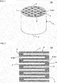
- the honeycomb structure includes, as in a honeycomb structure 100 shown in Fig. 1 and Fig. 2 , a honeycomb structure part 6 having porous partition wall 5 and porous plugged portions 8.
- the partition wall 5 defines a plurality of cells 4 extending from a first end face 2 as one end face to the second end face 3 as another end face and serving as through channels of fluid.
- the plugged portions 8 are arranged at an end part on the first end face side 2 of a first cell 4a as a predetermined cell and at an end part on the second end face 3 side of a second cell 4b as a remaining cell, among the plurality of cells 4.
- the first cell 4a and the second cell 4b are alternately arranged.
- Fig. 1 is a perspective view schematically showing a honeycomb structure.
- Fig. 2 is a cross-sectional view schematically showing a cross section parallel to the cell extending direction of the honeycomb structure shown in Fig. 1 .
- the porosity of the partition wall 5 is preferably 30 to 80%, more preferably 35 to 75%, and especially preferably 40 to 70%. When the porosity of the partition wall 5 is within the ranges, it is possible to hold the structural strength of the partition wall 5 while reducing the pressure loss.
- the "porosity of the partition wall 5" is a value measured by a mercury porosimeter.
- the thickness of the partition wall 5 is preferably 0.05 to 1.25 mm, more preferably 0.075 to 1.00 mm, and especially preferably 0.10 to 0.75 mm.
- the thickness of the partition wall 5 is less than 0.05 mm, the structural strength of the partition wall 5 might be insufficient.
- the thickness of the partition wall 5 exceeds 1.25 mm, the pressure loss tends to increase.
- the "thickness of the partition wall 5" in the present specification means a thickness of the partition wall 5 separating two neighboring cells 4 in a cross section perpendicular to the cell extending direction.
- the "thickness of the partition wall 5" can be measured by an image analyzer (produced by Nikon, product name: NEXIV, VMR-1515), for example.
- the average pore size of the partition wall 5 is preferably 3 to 50 ⁇ m, more preferably 5 to 40 ⁇ m, and especially preferably 7 to 30 ⁇ m.
- the average pore size of the partition wall 5 is less than 3 ⁇ m, pressure loss tends to increase.
- the average pore size of the partition wall 5 exceeds 50 ⁇ m, trapping efficiency tends to reduce.
- the "average pore size of the partition wall 5" in the present specification is a value measured by a mercury porosimeter.
- the cell density of the honeycomb structure part 6 is preferably 7.75 to 93.00 cells/cm 2 , more preferably 15.50 to 77.50 cells/cm 2 , and especially preferably 23.25 to 62.00 cells/cm 2 .
- the "cell density” in the present specification is the number of cells per unit area (per 1 cm 2 ) in a cross section perpendicular to the cell extending direction.
- the shape of the cells 4 in a cross section perpendicular to the cell extending direction is not particularly limited, and example of the shapes are a polygonal shape such as a quadrangular shape, a triangular shape or an octagonal shape, a circular shape, or an oval shape.
- the open frontal area of the cells is preferably 30 to 90%, more preferably 40 to 90%, and especially preferably 50 to 90%.
- the "open frontal area of the cells” in the present specification is the ratio (percentage ratio) of the total cross-sectional area of all of the cells 4 to the whole cross-sectional area of the honeycomb structure part 6 in a cross section perpendicular to the cell extending direction of the honeycomb structure part 6.
- the thickness of the outer peripheral wall 7 is not particularly limited.
- the thickness of the outer peripheral wall 7 is preferably 0.025 to 0.500 mm, more preferably 0.050 to 0.475 mm, and especially preferably 0.075 to 0.450 mm.
- the thickness of the outer peripheral wall 7 is 0.025 mm or more, the structural strength of the outer peripheral wall 7 can be hold.
- the thickness of the outer peripheral wall 7 exceeds 0.500 mm, the pressure loss tends to increase.
- the shape of the honeycomb structure part 6 is not particularly limited.
- a cylindrical shape, a tubular shape having an oval shaped bottom face, or a tubular shape having a polygonal shaped bottom face such as a quadrangle, a pentagonal or a hexagonal are preferable, and a cylindrical shape is more preferable.
- the size of the honeycomb structure part 6 (honeycomb structure 100) also is not particularly limited.
- the length in the cell extending direction of the honeycomb structure part 6 (honeycomb structure 100) is preferably of 50 to 500 mm.
- the diameter of the bottom face is preferably 50 to 800 mm.
- the partition wall 5 includes cordierite as a main component.
- partition wall 5 includes cordierite as a main component, it is possible to obtain a honeycomb structure having a small coefficient of thermal expansion and being superior in thermal shock resistance.
- the "partition wall 5 includes cordierite as a main component” it means that 50 mass% or more of cordierite is contained in the partition wall 5.
- the outer peripheral wall 7 preferably includes cordierite as a main component. When it is cordierite, it is possible to obtain a honeycomb structure having a small coefficient of thermal expansion and being superior in thermal shock resistance.
- the other materials of the outer peripheral wall 7, for example, may be at least one type selected from the following group. That is, as in the other materials of the outer peripheral wall 7, it may be at least one type selected from the group consisting of silicon carbide, a silicon-silicon carbide composite material, mullite, alumina, spinel, a silicon carbide-cordierite composite material, lithium aluminum silicate, and aluminum titanate.
- the plugged portions 8 are porous, and hence a plurality of pores are formed in the plugged portions 8.
- the plugged portions 8 include cordierite as a main component.
- the plugged portions 8 include cordierite as a main component, it is possible to obtain a honeycomb structure having a small coefficient of thermal expansion and being superior in thermal shock resistance.
- the "plugged portions 8 includes cordierite as a main component” it means that 50 mass% or more of cordierite is contained in the plugged portions 8.
- the porosity of the plugged portions 8 is preferably 30 to 80%. When the porosity of the plugged portions 8 is less than 30%, the pressure loss is increased. When the porosity of the plugged portions 8 exceeds 80%, the strength of the plugged portions is too low, and the plugged portions 8 may fall out at the time of using. In addition, when the porosity of the plugged portions 8 exceeds 80%, the particulate matter is easy to leak when using the honeycomb structure 100 as a filter for trapping particulate matter. Furthermore, the porosity of the plugged portions 8 is more preferably 35 to 75%, and is particularly the most preferably 40 to 70%.
- porosity of the plugged portions 8 is a value measured by a mercury porosimeter.
- the porosity of the plugged portions 8, compared with the porosity of the partition wall 5, is preferably the same as or higher, more preferably higher by 2% or more, and particularly the most preferably higher by 4% or more.
- the porosity of the plugged portions 8 is the same as or higher compared with the porosity of the partition wall 5, it can suppress a difference in stiffness at the boundary between the partition wall 5 and the plugged portions 8, and as a result, occurrence of cracks can be suppressed.
- the average pore size of the plugged portions 8 is preferably 4 to 70 ⁇ m, more preferably 7 to 60 ⁇ m and particularly preferably 10 to 50 ⁇ m. When the average pore size is within this range, it can suppress increase in the pressure loss to keep the trapping efficiency. When the average pore size of the plugged portions 8 is less than 4 ⁇ m, the pressure loss tends to increase. When the average pore size of the plugged portions 8 exceeds 70 ⁇ m, the trapping efficiency tends to reduce.
- the depth of the plugged portions 8 is preferably 1 to 25 mm, and more preferably 2 to 20 mm.
- the depth of the plugged portions 8 means the length in the extending direction of the cells 4 of the plugged portions 8.
- cordierite forming raw materials A alumina, aluminum hydroxide, kaolin, talc and silica were used.
- 1 part by mass of pore former 32 parts by mass of dispersion medium, 6 parts by mass of organic binder and 1 part by mass of dispersant were added, and then mixed and kneaded to prepare a kneaded material.
- dispersion medium water was used, and as the pore former, resin balloon having an average particle size of 40 ⁇ m was used.
- organic binder hydroxypropyl methylcellulose was used, and as the dispersant, ethylene glycol was used.
- the kneaded material was extruded by using a predetermined die, to prepare a honeycomb formed body including partition walls defining a plurality of cells extending from a first end face to a second end face.
- a honeycomb formed body including partition walls defining a plurality of cells extending from a first end face to a second end face.
- the shape of the cells in a cross section perpendicular to the cell extending direction was quadrangular, and the whole shape was cylindrical shape.
- the prepared honeycomb formed body was dried by a microwave drier, and then was completely dried by a hot air drier, to obtain the dried honeycomb formed body (honeycomb dried body). Then, both end parts of the honeycomb dried body were cut to predetermined dimensions. Incidentally, in the honeycomb dried body, a diameter at the central part in the central axis direction (cell extending direction) was the same as diameters at the end faces.
- a mask was attached to the first end face of the honeycomb dried body. At this time, all open areas of the cells at the first end face were covered with the mask. Next, the holes were made at predetermined portions of the mask (i.e., the parts covering predetermined cells) by irradiating the laser.
- the end face (the first end face), where the mask was attached, of this honeycomb dried body was directed upward, and a plugging material was continuously slide into the cell openings on the first end face side of the predetermined cells by using a rubber spatula of an automatic printer. Specifically, the plugging material prepared in advance was slide into the cell openings in a plurality of times without adding any new plugging material. In this way, the aforementioned plugging material was filled into the end parts on the first end face side of the predetermined cells (first cells).
- the plugging material was made of cordierite forming raw material B, 5.0 mass %of resin balloon (a copolymer of acrylonitrile having an average particle size of 40 ⁇ m and a shell wall thickness of 0.2 ⁇ m), 35 mass% of water, 2% of organic binder and 1% of dispersant.
- alumina, aluminum hydroxide, kaolin, talc and silica were used.
- Detailed conditions on the cordierite forming raw material B are shown in Table 1.
- a difference in firing shrinkage rate from the honeycomb formed body was 0.0% (Table 1).
- the viscosity (25°C) of the plugging material was 280 dPa ⁇ s.
- the viscosity of the plugging material was measured by a rotary viscometer.
- a mask was attached to the second end face of the honeycomb dried body. At this time, all open areas of the cells at the second end face were covered with the mask. Next, the holes were made at predetermined parts of the mask (i.e., the parts covering the second cells) by irradiating the laser.
- the end face (the second end face), where the mask was attached, of this honeycomb dried body was directed upward, and the aforementioned plugging material was continuously slide into cell openings on the second end face side of the remaining cells (the second cells) by using the rubber spatula of the automatic printer in the same manner as in the aforementioned first end face.
- one type of plugging material prepared in advance was slide into the cell openings in a plurality of times without adding any new plugging material. In this way, the aforementioned plugging material was filled into the end part on the second end face side of the second cells.
- honeycomb dried body where the plugging material was filled as stated above was dried by a hot air drier. Then, the resultant was fired at 1,410 to 1,440°C for 5 hours. In this way, a honeycomb structure was prepared.
- the resulting honeycomb structure had a nominal diameter of 143.8 mm and a length of 152.4 mm in the central axis direction.
- a value (L/D) of the ratio of a length L in the central axis direction to a diameter D of the honeycomb structure was 1.06.
- a cell density of the honeycomb structure was 46.5 cells/cm 2 .
- the thickness of the partition wall was 0.3 mm. Open frontal areas of the cells at both the end faces of the honeycomb structure were 62.8%, respectively.
- the porosity of the partition wall was 48%.
- the average pore size of the partition wall was 12 ⁇ m.
- the "nominal diameter" means an aimed center value of the diameter for this product.
- Honeycomb structures of Comparative Examples 1 and 2 were prepared similarly to Example 1 except that conditions were changed as shown in Table 1.
- Table 1 Plugging material porosity of partition wall (%) porosity of plugged portion (%) ratio of dimensional difference between end face and center part (%) difference from nominal diameter of 143.8 mm (mm) Necessity of outer peripheral coating thermal shock resistance resin balloon (mass%)* 1 aluminum hydroxide ratio (%)* 2 talc particle dia. ( ⁇ m) silica (mass%)* 1 difference in firing shrinkage rate (%)* 3 difference in crack generation temperature from Ex. 1 (°C) judgment Ex. 1 5.0 65 25 9 0.0 48 65 0 0 unnecessary 0 OK Ex. 2 7.5 45 25 11 1.0 48 70 0.15 0.22 unnecessary 15 OK Ex.
- honeycomb structures of Examples 1 to 4 and Comparative Examples 1 and 2 were evaluated for [porosity of partition wall], [porosity of plugged portions], [ratio in dimensional difference between end faces and central part], [necessity of outer periphery coating], and [thermal shock resistance]. Methods for evaluations are as follows.
- the porosity (%) of the partition wall was measured by a mercury porosimeter (mercury intrusion technique).
- the product name: Auto Pore III type 9405, produced by Micromeritics Corporation was used.
- the porosity (%) of the plugged portions was measured by a mercury porosimeter (mercury intrusion technique).
- the product name: Auto Pore III type 9405, produced by Micromeritics Corporation was used.
- the honeycomb structure was used as a DPF, and soot depositing amount was increased successively to perform regeneration (combustion of soot), and then the limit where crack occurs was checked.
- a non-thermally expandable ceramic mat as a holding material was wrapped around the outer periphery of the honeycomb structure, and the resultant was inserted into a canning body of stainless steel (SUS 409) to prepare a canning structure.
- combustion gas including soot generated by burning of the diesel fuel (light oil) was allowed to flow from one end face (the first end face) of the honeycomb structure and to flow out from another end face (the second end face), to deposit the soot in the honeycomb structure.
- the combustion gas at 650°C was allowed to flow from the first end face of the honeycomb structure.
- the flow amount of the combustion gas was reduced to burn the soot quickly.
- whether crack occurs in the honeycomb structure was checked.
- the soot depositing amount was increased successively again to perform regeneration (combustion of soot), and then increasing the temperature generated inside of the honeycomb structure.
- the highest temperature where no cracks occurred was "thermal shock resistance temperature”.
- the column of “evaluation” in the “evaluation of thermal shock resistance” shows “OK (pass)” when the thermal shock resistance temperature was 1,260°C or higher and shows “NG (failure)” when the thermal shock resistance temperature was less than 1,260°C.
- Table 1 shows a difference in thermal shock resistance temperature from the honeycomb structure of Example 1.
- Examples 1 to 4 did not need to include the outer periphery coating, and had favorable thermal shock resistance. On the other hand, Comparative Example 1 had poor thermal shock resistance. Comparative Example 2 needed to include the outer periphery coating.
- the present invention is applicable to a method for manufacturing a honeycomb structure capable of using as an exhaust gas purification filter.
Description
- The present invention relates to a method for manufacturing a honeycomb structure capable of using as an exhaust gas purification filter.
- Heretofore, honeycomb structures have been used as a trapping filter to remove particulate matter (PM) discharged from a diesel engine or the like. As a honeycomb structure used as a trapping filter for particulate matter, there has been used a plugged honeycomb structure provided with plugged portions at predetermined position of the both end faces.
- Herein, a plugged honeycomb structure includes a honeycomb structure part having porous partition walls defining a plurality of cells serving as through channels of fluid, and plugged portions provided with an end part of a predetermined cell (first cell) on the fluid inflow-side and with an end part of a remaining cell (second cell) on the fluid outflow-side. These plugged portions are generally arranged so that the first cell and the second cell are alternately arranged to form a so-called checker board pattern. According to such a plugged honeycomb structure, when exhaust gas flows into the cells from the end face on the exhaust gas inflow side, the exhaust gas flowing into the cells passes through the partition wall. Then, as the exhaust gas passes through the partition wall, the PM contained in the exhaust gas is trapped by the partition wall. Therefore, the exhaust gas passing through the partition wall is discharged as purified gas.
- The plugged honeycomb structure is prepared by filling a plugging material serving as a material of the plugged portions into cell openings of the honeycomb formed body, which is formed into a honeycomb shape with a use of kneaded material, followed by firing. A ceramic raw material is contained both in the kneaded material serving as a material of the honeycomb formed body and in the plugging material serving as a material of the plugged portions, but there is a difference in firing shrinkage rate between the honeycomb formed body and the plugging material during firing.
- As a case where there is a difference in firing shrinkage rate between the honeycomb formed body and the plugging material during firing, it can be divided broadly into a case, where the shrinkage of the honeycomb formed body is larger than that of the plugging material during firing, and the opposed case, where the shrinkage of the plugging material is larger than that of the honeycomb formed body during firing.
- When the honeycomb formed body shrinks more than the plugging material, in the honeycomb structure obtained after firing, the shrinkage at end face part having a plugged portion is smaller than the central part having no plugged portion. This is because that a plugging material does not shrink so much as the honeycomb formed body during firing, and hence the end face part of the honeycomb formed body is constrained by the low shrinkage of the plugging material. Therefore, a diameter at the end face part of the honeycomb structure becomes larger than that at the central part. As a result, honeycomb structure should have originally in cylindrical shape, but it becomes a concave drum shape. When the deformation of such a concave drum shape is remarkable, it becomes impossible to keep the diameter of the honeycomb structure within predetermined dimensional tolerance. Therefore, it becomes necessary to grind the outer periphery of the honeycomb structure to a cylindrical shape after firing, and then to perform the outer coating.
- In addition, when the honeycomb formed body shrinks more than the plugging material, the end face part of the honeycomb formed body is constrained by the low shrinkage of plugging material as stated above, and hence compressive stress remains in the end face part of the honeycomb structure obtained after firing. However, this residual compressive stress hardly causes a problem of decrease in thermal shock resistance in the honeycomb structure. This is because that, when the honeycomb structure is used as a filter for trapping particulate matter, the compressive stress remaining in the end face part is offset by tensile stress generated at the time of burning and removing the deposited particulate matter.
- On the other hand, when the plugging material shrinks more than the honeycomb formed body, a plugging material excessively shrinks at the end face part. Therefore, a gap is often generated between the plugged portion and the partition wall at the end face part of the honeycomb structure obtained after firing. Such a gap may cause the lacking of the plugged portion or cause the leakage of particulate matter when the honeycomb structure is used as a filter for trapping particulate matter. Moreover, when the plugging material shrinks more than the honeycomb formed body, there is a case where the aforementioned gap is not generated, but in such a case, the end face part having the plugged portion shrinks more than the central part having no plugged portion. This is because that plugging material shrinks more than the honeycomb formed body during firing, and hence the end face part of the honeycomb structure is constrained by the high shrinkage of the plugging material. As a result, the honeycomb structure should have originally in cylindrical shape, but it becomes a barrel shape. When the deformation of such a barrel shape is remarkable, it becomes impossible to keep the diameter of the honeycomb structure within predetermined dimensional tolerance. Therefore, it becomes necessary to grind the outer periphery of the honeycomb structure to a cylindrical shape after firing, and then to perform the outer coating.
- In addition, when the plugging material shrinks more than the honeycomb formed body, the end face part of the honeycomb formed body is constrained by the high shrinkage of plugging material as stated above, and hence tensile stress remains in the end face part of the honeycomb structure obtained after firing. When a honeycomb structure is used as a filter to trap particulate matter, high heat is generated inside the honeycomb structure at the time of burning and removing the deposited particulate matter. The honeycomb structure is expanded due to this high heat, and hence high tensile stress is generated in the honeycomb structure. As stated above, when tensile stress remains in the end face part of the honeycomb structure by a difference in firing shrinkage rate between the honeycomb formed body and the plugging material, it would be overlapped to the tensile stress resulting from the burning of the particulate matter. Thus generated overlapped tensile stress might be exceeded the structural strength of the honeycomb structure. Consequently, when the plugging material shrinks more than the honeycomb formed body, thermal shock resistance might be reduced in the honeycomb structure obtained after firing.
- In order not to reduce the thermal shock resistance of the honeycomb structure, it is needed to limit the difference in firing shrinkage rate between the plugging material and the honeycomb formed body to a predetermined value or less. Under such a background, there has been proposed a method for manufacturing a plugged honeycomb structure, wherein a difference in firing shrinkage rate between the honeycomb formed body and the plugging material is 7% or less (Patent Document 1).
- [Patent Document 1]
WO 2004/085029 -
US 2007/0044444 describes a honeycomb structured body in which a plurality of porous ceramic members are combined with one another through an adhesive layer, each of the porous ceramic members having a plurality of cells which are allowed to penetrate in a longitudinal direction with a wall portion therebetween and either one end of which is sealed, with a catalyst supporting layer being adhered to said wall portion, wherein pores formed in said porous ceramic member are constituted by large pores having a relatively large pore diameter and small pores having a relatively small pore diameter, and supposing that: the thickness of the catalyst supporting layer is X1(µm), and the value, obtained by multiplying the porosity (%) of said porous ceramic member by the ratio (the average pore diameter of said large pores/the average pore diameter of said small pores) of the average pore diameter of said large pores to the average pore diameter of said small pores, is Y1, these X1 and Y1 are allowed to satisfy the following inequalities (1) and (2):

-
US 2007/0269634 describes a honeycomb structure and a method for producing the honeycomb structure. There is provided a method for producing a cordierite honeycomb structure including the step of firing a honeycomb formed body. In the firing step, a temperature rise rate from 1200°C to 1250°C is controlled to 40°C/hr or more, a temperature rise rate from 1250°C to 1300°C is controlled to 2 to 40°C/hr, and a temperature rise rate from 1300°C to 1400°C is controlled to 40°C/hr or more. There is further provided a honeycomb structure having a porosity of 50 to 70%, a mean pore diameter of 15 to 30 µm, a difference in a mean pore diameter of 5 µm or less between in the central portion and in the outer peripheral portion, a thermal expansion coefficient of 1.0x10⁻⁶/°C or less in each of the central portion and the outer peripheral portion, and an A-axis compression strength of 1.5 MPa or more in each of the central portion and the outer peripheral portion. -
US 2008/0124516 describes a method for producing a porous ceramic structure wherein as a pore-forming agent, hollow particles (microcapsules) made of an organic resin are used, and as at least one type of raw material particles, particles are used which contain 30 to 100 mass % of particles (spherical particles) having a circularity of 0.70 to 1.00 with respect to the total mass of the particles. -
EP 2 335 797 -
JP 2011 230028 A - However, even though the above method for manufacturing a plugged honeycomb structure is used, in the plugged honeycomb structure immediately after firing, width at the end part in the cell extending direction (diameter of the end face) still might be too large or too small compared with the width at the central part.
- Additionally, since the honeycomb formed body is formed by extrusion, the partition wall of the honeycomb formed body has high degree of compression density and crystals tend to be oriented in the partition wall of the honeycomb structure obtained after firing. On the other hand, since the plugging material is simply pressed into the cell openings of the honeycomb formed body, the plugging material filled into the cell openings has low degree of compression density and orientation of crystals is hard to occur at the plugged portion obtained after firing. To reflect such differences, even when a ceramic raw material having the same composition are used in the honeycomb formed body and the plugging material, there would occur a difference in firing shrinkage rate between the honeycomb formed body and the plugging material. Therefore, in the aforementioned method for manufacturing a plugged honeycomb structure, while a difference in firing shrinkage rate between the honeycomb formed body and the plugging material is 7% or less, it is actually very difficult to keep the difference in firing shrinkage rate between the honeycomb formed body and the plugging material within the range of -2.0 to +2.0%.
- Then, when it is impossible to keep the difference in firing shrinkage rate between the honeycomb formed body and the plugging material within the range of -2.0 to +2.0%, it is needed to a step for grinding the outer periphery of the plugged honeycomb structure after firing, to adjust the size and the shape. In the case of grinding the outer periphery, it is needed to form an outer peripheral wall by applying the coating at the ground face. Especially in a conventional plugged honeycomb structure, it is essential to perform the outer grinding and outer coating when increasing the size.
- Furthermore, even when the outer peripheral coating is not required by keeping the difference in firing shrinkage rate between the honeycomb formed body and the plugging material within the range of -2.0 to +2.0%, in the obtained honeycomb structure, thermal shock resistance might be poor.
- The present invention provides the following method for manufacturing a honeycomb structure.
- [1] A method for manufacturing a honeycomb structure, comprising: a honeycomb formed body preparing step of extruding a kneaded material obtained by kneading a forming raw material containing a cordierite forming raw material A into a honeycomb shape, to prepare a honeycomb formed body having partition walls defining a plurality of cells extending from a first end face as one end face to a second end face as another end face; a plugged honeycomb formed body preparing step of filling cell openings of the prepared honeycomb formed body with a plugging material which includes a forming raw material containing a cordierite forming raw material B and resin balloon of 5 to 7.5 mass% and has a difference in firing shrinkage rate of -1.0 to +2.0% from the honeycomb formed body, to prepare a plugged honeycomb formed body; the difference in firing shrinkage rate from the honeycomb formed body being the difference between (a) the shrinkage rate (%) in dimension before and after firing of the plugging material; and (b) the shrinkage rate (%) in dimension before and after firing at the honeycomb formed body; and a honeycomb structure preparing step of firing the prepared plugged honeycomb formed body to prepare a honeycomb structure provided with porous plugged portions at an end part on a first end face side of a first cell as a predetermined cell and at an end part on the second end face side of a second cell as a remaining cell, among the plurality of cells; wherein the cordierite forming raw material B includes silica having an average particle diameter of 1 to 5 µm.
- [2] The method for manufacturing a honeycomb structure according to [1], wherein the cordierite forming raw material B includes alumina and aluminum hydroxide, and a percentage ratio of the mass of the aluminum hydroxide to sum of the mass of the alumina and the mass of the aluminum hydroxide contained in the cordierite forming raw material B is 20 to 100%.
- [3] The method for manufacturing a honeycomb structure according to [1] or [2], wherein the cordierite forming raw material B includes talc having an average particle diameter of 5 to 30 µm.
- [4] The method for manufacturing a honeycomb structure according to any one of [1] to [3], wherein the cordierite forming raw material B includes 5 to 20 mass% of silica.
- [5] The method for manufacturing a honeycomb structure according to any one of [1] to [4], wherein the percentage ratio of mass of the aluminum hydroxide to sum of mass of the alumina and the mass of the aluminum hydroxide contained in the cordierite forming raw material B is 45 to 70%.
- [6] The method for manufacturing a honeycomb structure according to any one of [1] to [5], wherein the content of silica in the cordierite forming raw material B is 9 to 13 mass%.
- According to the method for manufacturing a honeycomb structure of the present invention, it is possible to reduce the width of the dimensional size generated during firing between the end part and the central part in the honeycomb structure by using a plugging material which includes a forming raw material containing a ceramic forming raw material and resin balloon of 1 to 15 mass% and has a difference in firing shrinkage rate of - 1.0 to +2.0% from the honeycomb formed body. Specifically, it is kept the difference in firing shrinkage rate in diameter between the end parts and the central part in the honeycomb structure within the range of -0.2 to +0.35% (in the case of the absence of a dimensional difference before firing between the end parts and the central part in the honeycomb structure of 143.8 mm in diameter, the range is -0.29 to 0.50 mm).
- Moreover, according to the honeycomb structure described herein, the shape distortion between the end parts and the central part in the cell extending direction is suppressed. In addition, according to the method for manufacturing a honeycomb structure of the present invention, it promotes the integration of the plugging material and the honeycomb formed body during firing by using a plugging material having a predetermined structure, to prevent the generation of the aforementioned gap.
- Furthermore, according to the method for manufacturing a honeycomb structure of the present invention, it is possible to suppress the reduction of thermal shock resistance and to promote the integration of the plugging material and the honeycomb formed body during firing by using a plugging material which includes a forming raw material containing a ceramic forming raw material and resin balloon of 1 to 15 mass% and has a difference in firing shrinkage rate of -1.0 to +2.0% from the honeycomb formed body.
-
-
Fig. 1 is a perspective view schematically showing a honeycomb structure. -
Fig. 2 is a cross-sectional view schematically showing a cross section parallel to the cell extending direction of the honeycomb structure shown inFig. 1 . - Hereinafter, the embodiments of the present invention are described with reference to the drawings.
- One embodiment of a method for manufacturing a honeycomb structure of the present invention includes a
honeycomb formed body preparing step, a plugged honeycomb formed body preparing step, and a honeycomb structure preparing step. In the honeycomb formed body preparing step, it extrudes a kneaded material obtained by kneading a forming raw material containing a cordierite forming raw material A into a honeycomb shape. In this extrusion, it forms a honeycomb formed body having partition walls defining a plurality of cells extending from a first end face as one end face to a second face as another end face. In the plugged honeycomb formed body preparing step, a plugged honeycomb formed body is prepared by filling the cell openings in the prepared honeycomb formed body with plugging materials which include a forming raw material containing a cordierite forming raw material B, water, binder, dispersant, surfactant and resin balloon of 1.0 to 15 mass%, and has a difference in firing shrinkage rate of -1.0 to +2.0% from the honeycomb formed body. In the honeycomb structure preparing step, the prepared plugged honeycomb formed body is fired, to prepare a honeycomb structure provided with porous plugged portions at an end part on a first end face side of a first cell as a predetermined cell and at an end part on the second end face side of a second cell as a remaining cell, among the plurality of cells. - According to the method for manufacturing a honeycomb structure of the present embodiment, it is possible to reduce the width of the dimensional size generated during firing between the end part and the central part in the honeycomb structure by using a plugging material which includes resin balloon of 1 to 15 mass% and has a difference in firing shrinkage rate of -1.0 to +2.0% from the honeycomb formed body. In this way, since it is possible to reduce the width of dimensional difference, according to the method for manufacturing a honeycomb structure of the present embodiment, it is possible to omit the steps of grinding outer periphery of the honeycomb structure after firing and coating the ground outer periphery of the honeycomb structure with an outer peripheral coating material.
- Hereinafter, each of steps of the method for manufacturing a honeycomb structure of the present embodiment is described in more detail.
- In the honeycomb formed body preparing step, it extrudes a kneaded material obtained by kneading a forming raw material into a honeycomb shape, to obtain a honeycomb formed body.
- The forming raw material is preferably a material prepared by adding dispersion medium and additive to a cordierite forming raw material A. Example of additives includes organic binder, pore former and surfactant. Example of dispersion medium includes water.
- The "cordierite forming raw material A" is a ceramic raw material blended to have chemical compositions in the range of 42 to 56 mass% of silica, 30 to 45 mass% of alumina and 12 to 16 mass% of magnesia, and forms cordierite after firing. For instance, a cordierite forming raw material A can be obtained by blending alumina, aluminum hydroxide, kaolin, talc and silica at a predetermined ratio.
- Example of organic binder includes methyl cellulose, hydroxypropoxyl cellulose, hydroxyethyl cellulose, carboxymethyl cellulose, or polyvinyl alcohol. Among them, methyl cellulose and hydroxypropoxyl cellulose are preferably used together. The content of the organic binder is preferably 0.2 to 8 parts by mass with respect to 100 parts by mass of the cordierite forming raw material A.
- As long as the pore former forms the pores by firing, it is not particularly limited. Example of pore former includes starch, resin balloon, water absorbing resin, silica gel. The content of the pore former is preferably 0.5 to 25 parts by mass with respect to 100 parts by mass of the cordierite forming raw material A.
- Ethylene glycol, dextrin, fatty acid soap, or polyalcohol or the like can be used as surfactant. They may be used alone. They also may be used in combination of two or more types. The content of the surfactant is preferably 0.1 to 2 parts by mass with respect to 100 parts by mass of the cordierite forming raw material A.
- The content of the dispersion medium is preferably 10 to 100 parts by mass with respect to 100 parts by mass of the cordierite forming raw material A.
- The particle diameter as well as the amount of the cordierite forming raw material A (aggregate particles) to be used (e.g., the particle diameters and the amounts of alumina, aluminum hydroxide, kaolin, talc and silica) and the particle diameter as well as the amount of the pore former to be added may have be adjusted. The porous substrate having a desired porosity and average pore size can be obtained by adjusting the particle diameter and the amount of such a pore former.
- A method for forming a kneaded material by kneading a forming raw material is not particularly limited. For instance, there is a method using a kneader or a vacuum clay kneader.
- In the extrusion, it extrudes a kneaded material into a honeycomb shape, to obtain a honeycomb formed body. The extrusion may be performed by using a die. As to the die, shape of slits (the shape of pins surrounded with slits), slits width, density of the pins and the like may be appropriately designed so as to correspond to the cell shape of the honeycomb formed body, the shape of intersections of the partition wall, the thickness of the partition wall and the cell density. As a material of the die, a super hard metal alloy being hard to wear is preferable.
- Thus, a honeycomb formed body can be obtained. The honeycomb formed body has partition walls defining a plurality of cells extending from a first end face as one end face to a second end face as another end face.
- A plugging material to be used at the plugged honeycomb formed body preparing step includes a forming raw material containing a cordierite forming raw material B and a resin balloon of 1.0 to 15 mass%. In addition, the plugging material to be used at the plugged honeycomb formed body preparing step has a difference in firing shrinkage rate of -1.0 to +2.0% from the honeycomb formed body.
- In the present specification, a "difference in firing shrinkage rate from the honeycomb formed body" means a difference between "a shrinkage rate (%) in dimension before and after firing at the plugging material" and "a shrinkage rate (%) in dimension before and after firing at the honeycomb formed body". Hereinafter, for convenience of explanation, the "difference between "a shrinkage rate (%) in dimension before and after firing at the plugging material" and "a shrinkage rate (%) in dimension before and after firing at the honeycomb formed body"" is referred to as a "difference in firing shrinkage rate". Additionally, when the "shrinkage rate (%) in dimension before and after firing at the plugging material" is negative, it means that the plugging material shrinks by firing. When the "shrinkage rate (%) in dimension before and after firing at the honeycomb formed body" is negative, it means that the honeycomb formed body shrinks by firing. A plugging material and a honeycomb formed body normally tend to shrink by firing. In such a normal case, when the "difference in firing shrinkage rate" is negative, the plugging material shrinks more than the honeycomb formed body by firing.
- Example of resin balloon includes copolymer such as vinylidene chloride, acrylonitrile.
- The content of resin balloon in the plugging material is normally 1.0 to 15 mass% in terms of solid content as stated above. The porosity can be increased by adding the resin balloon. It is possible to increase the shrinkage during firing by increasing the porosity, i.e., increasing the number of the pores. When the content of resin balloon in the plugging material is less than 1.0 mass%, the porosity is low and cracks easily occur at the boundary between plugged portions and partition walls due to a stiffness difference between the plugged portions and the partition walls. When the content of resin balloon in the plugging material exceeds 15 mass%, the porosity at the plugged portion may become too high or the pore size may become too large. When it is excessive high porosity or excessive large pore size, trapping efficiency might be reduced at the time of using the honeycomb structure as a filter for trapping particulate matter. The content of resin balloon in the plugging material is preferably 1.5 to 13 mass%, and in particular, more preferably 2.0 to 11 mass%. Moreover, when the content of resin balloon is within above ranges, since the resin balloon can hold water content, it is possible to prevent the generation of "sink" at the time of filling the plugging material by "sliding method" described later.
- An average particle diameter of the resin balloon is preferably 2 to 200 µm, more preferably 3 to 180 µm, and especially preferably 4 to 160 µm. When the average particle diameter of the resin balloon is within these ranges, pores (communicating pores) penetrating through the plugged portion is appropriately formed. Therefore, when the honeycomb structure is used as a filter for trapping particulate matter, the trapping efficiency can be maintained while suppressing the increase in pressure loss. When the average particle diameter of the resin balloon is less than 2 µm, the number of the communicating pores might be decreased. As a result, the pressure loss might be increased. When the average particle diameter of the resin balloon exceeds 200 µm, the number of the communicating pores might be increased. As a result, the trapping efficiency might be reduced.
- The shell wall thickness of the resin balloon is preferably 0.01 to 1.00 µm, more preferably from 0.10 to 0.5 µm, and especially preferably 0.15 to 0.45 µm. When the shell wall thickness of the resin balloon is less than 0.01 µm, the resin balloon might be easy to collapse at the time of filling the plugging material into the honeycomb structure part. Therefore, the effect of pore-forming might be reduced. When the shell wall thickness of the resin balloon exceeds 1.00 µm, the weight of the resin balloon increases, and hence cracks might be easy to occur during firing.
- Especially in the method for manufacturing a honeycomb structure of the present embodiment, a cordierite forming raw material A is used as a material of the partition wall and a cordierite forming raw material B is used as a material of the plugged portion (raw material of the plugging material). In this way, the partition wall and the plugged portion are made of the same type of material, whereby the "difference in firing shrinkage rate" is easy to control in the range of -1.0 to +2.0%.
- The "cordierite forming raw material A" in the present specification means a cordierite forming raw material included in a material of the partition wall. The "cordierite forming raw material B" in the present specification means a cordierite forming raw material included in a material of the plugged portion (plugging material). In the method for manufacturing a honeycomb structure of the present embodiment, the compositions of the "cordierite forming raw material A" and the "cordierite forming raw material B", depending on the specific embodiment, may be the same or be different.
- The cordierite forming raw material B includes alumina and aluminum hydroxide, and the percentage ratio of the mass of aluminum hydroxide to the sum of the mass of alumina and the mass of aluminum hydroxide (hereinafter called "aluminum hydroxide ratio" for convenience of explanation) included in the cordierite forming raw material B is preferably 20 to 100%. The "difference in firing shrinkage rate" can be easy to control by suitably changing the "aluminum hydroxide ratio" in the range of 20 to 100%. In addition, it is possible to increase the shrinkage during firing at the plugged portion by increasing the "aluminum hydroxide ratio". When the "aluminum hydroxide ratio" is less than 20%, a difference in coefficient of thermal expansion tends to occur between the partition wall and the plugged portion. Therefore, when the temperature rises during combustion of soot, cracks are easy to occur at the partition wall near a contacting part with the plugged portion in the honeycomb structure obtained after firing. Incidentally, when the "aluminum hydroxide ratio" is 100%, alumina is not contained in the cordierite forming raw material B.
- When the cordierite forming raw material B includes alumina, the average particle diameter of alumina is preferably 0.5 to 20 µm. When the average particle diameter of alumina included in the cordierite forming raw material B is less than 0.5 µm, the sliding inclusive property might be poor when filling the plugging material by the later "sliding method". When the average particle diameter of alumina included in the cordierite forming raw material B exceeds 20 µm, it might be needed to set the longer firing time than typical one. Moreover, the average particle diameter of alumina included in the cordierite forming raw material B is more preferably 1.0 to 15 µm, and is particularly the most preferably 1.5 to 10 µm.
- The cordierite forming raw material B preferably includes talc having an average particle diameter of 5 to 30 µm. When the cordierite forming raw material B includes talc having an average particle diameter of 5 to 30 µm, the shrinkage ratio during firing is easy to control, and hence the "difference in firing shrinkage rate" is easy to control in the range of -1.0 to +2.0%. When the average particle diameter of talc included in the cordierite forming raw material B is less than 5 µm, the flow property of the plugging material is poor when filling the plugging material into the cell openings, and hence it might be difficult to make the plugged portion a desired depth. When the average particle diameter of talc included in the cordierite forming raw material B exceeds 30 µm, the shrinkage during firing is hard to occur, and hence it might be difficult to control the "difference in firing shrinkage rate" in the range of -1.0 to +2.0%. The average particle diameter of talc included in the cordierite forming raw material B is more preferably 6 to 28 µm, and is particularly the most preferably 7 to 26 µm.
- The cordierite forming raw material B preferably includes silica of 5 to 20 mass%. Herein, the "mass%" represents the ratio when the overall amount of the cordierite forming raw material B is 100 mass%. When the content of silica in the cordierite forming raw material B is less than 5 mass%, the amount of kaolin included in the cordierite forming raw material B is too much, and hence it might be easy to occur the breakage during firing. When the content of silica in the cordierite forming raw material B exceeds 20 mass%, the shrinkage during firing is hard to occur, and hence it might be difficult to adjust the firing shrinkage rate of the plugging material to the firing shrinkage rate of the substrate (honeycomb formed body). Moreover, the content of silica in the cordierite forming raw material B is more preferably 7 to 18 mass%, and is particularly the most preferably 9 to 16 mass%. Herein, the "mass%" represents the ratio when the overall amount of the cordierite forming raw material B of the plugging material is 100 mass%.
- In addition, the cordierite forming raw material B includes silica having an average particle diameter of 1 to 5 µm. When the cordierite forming raw material B includes silica having an average particle diameter of 1 to 5 µm, the fitting property between the plugging material and the partition wall is superior when filling the plugging material into the cell openings. Therefore, a gap is hard to generate between the plugged portion and the partition wall after firing. When the average particle diameter of silica included in the cordierite forming raw material B is less than 1 µm, water
included in the plugging material is absorbed to the partition wall when filling the plugging material into the cell openings, and accordingly the plugging material is easy to concentrate on the partition wall. As a result, the sink occurs at the plugged portion, whereby it might cause the soot leakage when using the resulting honeycomb structure as a filter. When the average particle diameter of silica included in the cordierite forming raw material B exceeds 5 µm, the fitting property between the plugging material and the partition wall is not sufficient, and hence a gap might occur between the plugged portion and the partition wall. As a result, it might cause leakage of particulate matter when the resulting honeycomb structure is used as a filter for trapping the particulate matter. The average particle diameter of silica included in the cordierite forming raw material B is more preferably 1.5 to 4 µm, and is particularly the most preferably 2 to 3 µm. - The plugging material may include additives such as water, binder, dispersant and surfactant in addition to the forming raw material containing the ceramic raw material and the resin balloon.
- The viscosity of plugging material is preferably 30 to 2,000 dPa·s. When the viscosity of the plugging material is 30 to 2,000 dPa·s, it is possible to fill the plugging material into the cell openings sufficiently. In addition, it also can prevent the occurrence of sag of the plugging material when filling the plugging material into the cell openings. When the viscosity of the plugging material is less than 30 dPa·s, the plugging material might sag when filling the plugging material into the cell openings. When the viscosity of the plugging material exceeds 2,000 dPa·s, the filling property of the plugging material into the cell openings deteriorates, and hence it might be impossible to set the plugged portion till a desired depth. Moreover, the viscosity of the plugging material is more preferably 40 to 1,500 dPa·s, and is particularly the most preferably 50 to 1,000 dPa·s.
- Next, a plugged portion is formed by filling the plugging material into the honeycomb formed body, to prepare a plugged honeycomb formed body.
- First, a predetermined cell among the plurality of cells formed in the honeycomb formed body is defined as a first cell, and a remaining cell is defined as a second cell. Then, as to the first cell, the plugging material is filled at an end part on the first end face side. As to the second cell, the plugging material is filled at an end part on the second end face side.
- The following method (it may be called as "a sliding method" for convenience of explanation) can be used when filling the plugging material into the cell openings. A mask is attached to one end face (e.g., the first end face) of the honeycomb formed body. Next, a hole is made at a part of the mask covering the predetermined cell by known means such as a laser. Next, the honeycomb formed body is disposed so that the end face to which the mask is attached (the one end face) faces upward. Next, the above-mentioned plugging material is continuously slid into the upward directed end face. Similarly, the above-mentioned plugging material is filled into another end part of the remaining cell attached with the mask where the hole is made.
- Alternatively, the following masking step and press-fitting step may be used. The masking step is a step that a sheet is attached to one end face (e.g., the first end face) of the honeycomb formed body, and a hole is made at a position overlapping with a "cell where a plugged portion is to be formed" in the sheet. The press-fitting step is a step that the plugging material is pressed into the cells of the honeycomb formed body by pressing "end face of the honeycomb formed body on the side where the sheet is attached" into a container storing the plugging material. The plugging material is filled into only the cells communicating with the hole made at the sheet when pressing the plugging material into the cell of the honeycomb formed body.
- Next, the plugging material filled in the honeycomb formed body may be dried. The plugging material may be dried after filling the plugging material into the cell openings at both end faces of the honeycomb formed body. Alternatively, the plugging materials may be filled into the cell openings at one end face (e.g., the first end face) of the honeycomb formed body, followed by drying the plugging material, and then the plugging material may be filled into the cell openings at another end face (e.g., the second end face), followed by drying the plugging material.
- In the honeycomb structure preparing step, the aforementioned plugged honeycomb formed body is fired. Firing temperature can be appropriately determined depending on the material of the honeycomb formed body. When the material of the honeycomb formed body is cordierite, for example, the firing temperature is preferably from 1,380 to 1,450°C, and more preferably from 1,400 to 1,440°C. Moreover, the firing time is preferably from about 3 to 10 hours.
- The honeycomb formed body may be dried prior to firing. The drying method is not particularly limited. Example of the methods includes hot air drying, microwave drying, dielectric drying, reduced-pressure drying, vacuum drying, and freeze-drying. Among them, the dielectric drying, the microwave drying or the hot air drying is preferably performed alone or in combination. Moreover, as to drying conditions, it is preferable that drying temperature is 30 to 150°C and a drying time is 1 minute to 2 hours.
- Moreover, the honeycomb formed body is preferably calcined in advance before firing the honeycomb formed body. The calcination is performed for degreasing, the method is not particularly limited, and it may be needed to remove the organic matters (organic binder, dispersant, pore former and the like) in the honeycomb formed body. Generally, the combustion temperature of organic binder is about 100 to 300°C and the combustion temperature of pore former is about 200 to 800°C, and hence it is preferably calcined at about 200 to 1,000°C for about 3 to 100 hours under an oxidation atmosphere as the condition for calcination.
- Instead of filling the plugging material into the honeycomb formed body as stated above, the honeycomb formed body may be fired to prepare a honeycomb fired body, and then the plugging material may be filled into an end part of one end face side of a predetermined cell of the honeycomb fired body.
- Next, a honeycomb structure obtained by the method for manufacturing a honeycomb structure of the present embodiment as stated above is described.
- The honeycomb structure includes, as in a
honeycomb structure 100 shown inFig. 1 and Fig. 2 , ahoneycomb structure part 6 havingporous partition wall 5 and porous pluggedportions 8. Thepartition wall 5 defines a plurality ofcells 4 extending from afirst end face 2 as one end face to thesecond end face 3 as another end face and serving as through channels of fluid. The pluggedportions 8 are arranged at an end part on the firstend face side 2 of afirst cell 4a as a predetermined cell and at an end part on thesecond end face 3 side of asecond cell 4b as a remaining cell, among the plurality ofcells 4. In thehoneycomb structure part 6, thefirst cell 4a and thesecond cell 4b are alternately arranged. Therefore, the pluggedportions 8 are arranged so as to form a so-called checker board pattern in thefirst end face 2 and thesecond end face 3. Thehoneycomb structure 100 further has an outerperipheral wall 7 at the outer periphery of thehoneycomb structure part 6. The honeycomb structure does not necessarily need to have the outerperipheral wall 7.Fig. 1 is a perspective view schematically showing a honeycomb structure.Fig. 2 is a cross-sectional view schematically showing a cross section parallel to the cell extending direction of the honeycomb structure shown inFig. 1 . - The porosity of the
partition wall 5 is preferably 30 to 80%, more preferably 35 to 75%, and especially preferably 40 to 70%. When the porosity of thepartition wall 5 is within the ranges, it is possible to hold the structural strength of thepartition wall 5 while reducing the pressure loss. - In the present specification, the "porosity of the
partition wall 5" is a value measured by a mercury porosimeter. - The thickness of the
partition wall 5 is preferably 0.05 to 1.25 mm, more preferably 0.075 to 1.00 mm, and especially preferably 0.10 to 0.75 mm. When the thickness of thepartition wall 5 is less than 0.05 mm, the structural strength of thepartition wall 5 might be insufficient. When the thickness of thepartition wall 5 exceeds 1.25 mm, the pressure loss tends to increase. - The "thickness of the
partition wall 5" in the present specification means a thickness of thepartition wall 5 separating two neighboringcells 4 in a cross section perpendicular to the cell extending direction. The "thickness of thepartition wall 5" can be measured by an image analyzer (produced by Nikon, product name: NEXIV, VMR-1515), for example. - The average pore size of the
partition wall 5 is preferably 3 to 50 µm, more preferably 5 to 40 µm, and especially preferably 7 to 30 µm. When the average pore size of thepartition wall 5 is less than 3 µm, pressure loss tends to increase. When the average pore size of thepartition wall 5 exceeds 50 µm, trapping efficiency tends to reduce. The "average pore size of thepartition wall 5" in the present specification is a value measured by a mercury porosimeter. - The cell density of the
honeycomb structure part 6 is preferably 7.75 to 93.00 cells/cm2, more preferably 15.50 to 77.50 cells/cm2, and especially preferably 23.25 to 62.00 cells/cm2. When the cell density of thehoneycomb structure part 6 is less than 7.75 cells/cm2, a contact area between exhaust gas and thehoneycomb structure part 6 tends not to obtain sufficiently. When the cell density of thehoneycomb structure part 6 exceeds 93.00 cells/cm2, the pressure loss tends to increase. The "cell density" in the present specification is the number of cells per unit area (per 1 cm2) in a cross section perpendicular to the cell extending direction. - The shape of the
cells 4 in a cross section perpendicular to the cell extending direction is not particularly limited, and example of the shapes are a polygonal shape such as a quadrangular shape, a triangular shape or an octagonal shape, a circular shape, or an oval shape. - The open frontal area of the cells is preferably 30 to 90%, more preferably 40 to 90%, and especially preferably 50 to 90%. When the open frontal area of the cells is less than 30%, the pressure loss tends to increase. When the open frontal area of the cells exceeds 90%, the strength of the
honeycomb structure part 6 tends not to obtain sufficiently. The "open frontal area of the cells" in the present specification is the ratio (percentage ratio) of the total cross-sectional area of all of thecells 4 to the whole cross-sectional area of thehoneycomb structure part 6 in a cross section perpendicular to the cell extending direction of thehoneycomb structure part 6. - The thickness of the outer
peripheral wall 7 is not particularly limited. The thickness of the outerperipheral wall 7 is preferably 0.025 to 0.500 mm, more preferably 0.050 to 0.475 mm, and especially preferably 0.075 to 0.450 mm. When the thickness of the outerperipheral wall 7 is 0.025 mm or more, the structural strength of the outerperipheral wall 7 can be hold. When the thickness of the outerperipheral wall 7 exceeds 0.500 mm, the pressure loss tends to increase. - The shape of the
honeycomb structure part 6 is not particularly limited. A cylindrical shape, a tubular shape having an oval shaped bottom face, or a tubular shape having a polygonal shaped bottom face such as a quadrangle, a pentagonal or a hexagonal are preferable, and a cylindrical shape is more preferable. Moreover, the size of the honeycomb structure part 6 (honeycomb structure 100) also is not particularly limited. The length in the cell extending direction of the honeycomb structure part 6 (honeycomb structure 100) is preferably of 50 to 500 mm. Furthermore, when the outer shape of the honeycomb structure part 6 (the honeycomb structure 100) is cylindrical, for example, the diameter of the bottom face is preferably 50 to 800 mm. - The
partition wall 5 includes cordierite as a main component. Whenpartition wall 5 includes cordierite as a main component, it is possible to obtain a honeycomb structure having a small coefficient of thermal expansion and being superior in thermal shock resistance. When the "partition wall 5 includes cordierite as a main component", it means that 50 mass% or more of cordierite is contained in thepartition wall 5. - The outer
peripheral wall 7 preferably includes cordierite as a main component. When it is cordierite, it is possible to obtain a honeycomb structure having a small coefficient of thermal expansion and being superior in thermal shock resistance. The other materials of the outerperipheral wall 7, for example, may be at least one type selected from the following group. That is, as in the other materials of the outerperipheral wall 7, it may be at least one type selected from the group consisting of silicon carbide, a silicon-silicon carbide composite material, mullite, alumina, spinel, a silicon carbide-cordierite composite material, lithium aluminum silicate, and aluminum titanate. - The plugged
portions 8 are porous, and hence a plurality of pores are formed in the pluggedportions 8. - Moreover, the plugged
portions 8 include cordierite as a main component. When the pluggedportions 8 include cordierite as a main component, it is possible to obtain a honeycomb structure having a small coefficient of thermal expansion and being superior in thermal shock resistance. When the "pluggedportions 8 includes cordierite as a main component", it means that 50 mass% or more of cordierite is contained in the pluggedportions 8. - The porosity of the plugged
portions 8 is preferably 30 to 80%. When the porosity of the pluggedportions 8 is less than 30%, the pressure loss is increased. When the porosity of the pluggedportions 8 exceeds 80%, the strength of the plugged portions is too low, and the pluggedportions 8 may fall out at the time of using. In addition, when the porosity of the pluggedportions 8 exceeds 80%, the particulate matter is easy to leak when using thehoneycomb structure 100 as a filter for trapping particulate matter. Furthermore, the porosity of the pluggedportions 8 is more preferably 35 to 75%, and is particularly the most preferably 40 to 70%. - In the present specification, "porosity of the plugged
portions 8" is a value measured by a mercury porosimeter. - Moreover, the porosity of the plugged
portions 8, compared with the porosity of thepartition wall 5, is preferably the same as or higher, more preferably higher by 2% or more, and particularly the most preferably higher by 4% or more. When the porosity of the pluggedportions 8 is the same as or higher compared with the porosity of thepartition wall 5, it can suppress a difference in stiffness at the boundary between thepartition wall 5 and the pluggedportions 8, and as a result, occurrence of cracks can be suppressed. - The average pore size of the plugged
portions 8 is preferably 4 to 70 µm, more preferably 7 to 60 µm and particularly preferably 10 to 50 µm. When the average pore size is within this range, it can suppress increase in the pressure loss to keep the trapping efficiency. When the average pore size of the pluggedportions 8 is less than 4 µm, the pressure loss tends to increase. When the average pore size of the pluggedportions 8 exceeds 70 µm, the trapping efficiency tends to reduce. - The depth of the plugged
portions 8 is preferably 1 to 25 mm, and more preferably 2 to 20 mm. Herein, the depth of the pluggedportions 8 means the length in the extending direction of thecells 4 of the pluggedportions 8. - The following describes the present invention by way of examples in more details, but the present invention is not limited to these examples.
- As the cordierite forming raw materials A, alumina, aluminum hydroxide, kaolin, talc and silica were used. To 100 parts by mass of this cordierite forming raw material, 1 part by mass of pore former, 32 parts by mass of dispersion medium, 6 parts by mass of organic binder and 1 part by mass of dispersant were added, and then mixed and kneaded to prepare a kneaded material. As the dispersion medium, water was used, and as the pore former, resin balloon having an average particle size of 40 µm was used. As the organic binder, hydroxypropyl methylcellulose was used, and as the dispersant, ethylene glycol was used.
- Next, the kneaded material was extruded by using a predetermined die, to prepare a honeycomb formed body including partition walls defining a plurality of cells extending from a first end face to a second end face. In the honeycomb formed body, the shape of the cells in a cross section perpendicular to the cell extending direction was quadrangular, and the whole shape was cylindrical shape.
- Next, the prepared honeycomb formed body was dried by a microwave drier, and then was completely dried by a hot air drier, to obtain the dried honeycomb formed body (honeycomb dried body). Then, both end parts of the honeycomb dried body were cut to predetermined dimensions. Incidentally, in the honeycomb dried body, a diameter at the central part in the central axis direction (cell extending direction) was the same as diameters at the end faces.
- Next, a mask was attached to the first end face of the honeycomb dried body. At this time, all open areas of the cells at the first end face were covered with the mask. Next, the holes were made at predetermined portions of the mask (i.e., the parts covering predetermined cells) by irradiating the laser.
- Next, the end face (the first end face), where the mask was attached, of this honeycomb dried body was directed upward, and a plugging material was continuously slide into the cell openings on the first end face side of the predetermined cells by using a rubber spatula of an automatic printer. Specifically, the plugging material prepared in advance was slide into the cell openings in a plurality of times without adding any new plugging material. In this way, the aforementioned plugging material was filled into the end parts on the first end face side of the predetermined cells (first cells).
- It is to be noted that the plugging material was made of cordierite forming raw material B, 5.0 mass %of resin balloon (a copolymer of acrylonitrile having an average particle size of 40 µm and a shell wall thickness of 0.2 µm), 35 mass% of water, 2% of organic binder and 1% of dispersant. At the cordierite forming raw material B, alumina, aluminum hydroxide, kaolin, talc and silica were used. Detailed conditions on the cordierite forming raw material B are shown in Table 1. Furthermore, in the plugging material, a difference in firing shrinkage rate from the honeycomb formed body was 0.0% (Table 1). The viscosity (25°C) of the plugging material was 280 dPa·s. The viscosity of the plugging material was measured by a rotary viscometer.
- Next, a mask was attached to the second end face of the honeycomb dried body. At this time, all open areas of the cells at the second end face were covered with the mask. Next, the holes were made at predetermined parts of the mask (i.e., the parts covering the second cells) by irradiating the laser.
- Next, the end face (the second end face), where the mask was attached, of this honeycomb dried body was directed upward, and the aforementioned plugging material was continuously slide into cell openings on the second end face side of the remaining cells (the second cells) by using the rubber spatula of the automatic printer in the same manner as in the aforementioned first end face. Specifically, similarly to the case of filling the plugging material into the end part on the first end face side of the first cells, one type of plugging material prepared in advance was slide into the cell openings in a plurality of times without adding any new plugging material. In this way, the aforementioned plugging material was filled into the end part on the second end face side of the second cells.
- Next, the honeycomb dried body where the plugging material was filled as stated above was dried by a hot air drier. Then, the resultant was fired at 1,410 to 1,440°C for 5 hours. In this way, a honeycomb structure was prepared.
- The resulting honeycomb structure had a nominal diameter of 143.8 mm and a length of 152.4 mm in the central axis direction. A value (L/D) of the ratio of a length L in the central axis direction to a diameter D of the honeycomb structure was 1.06. A cell density of the honeycomb structure was 46.5 cells/cm2. The thickness of the partition wall was 0.3 mm. Open frontal areas of the cells at both the end faces of the honeycomb structure were 62.8%, respectively. The porosity of the partition wall was 48%. The average pore size of the partition wall was 12 µm. The "nominal diameter" means an aimed center value of the diameter for this product.
- Honeycomb structures of Examples 2 to 4 were prepared similarly to Example 1 except that conditions were changed as shown in Table 1.
- Honeycomb structures of Comparative Examples 1 and 2 were prepared similarly to Example 1 except that conditions were changed as shown in Table 1.
[Table 1] Plugging material porosity of partition wall (%) porosity of plugged portion (%) ratio of dimensional difference between end face and center part (%) difference from nominal diameter of 143.8 mm (mm) Necessity of outer peripheral coating thermal shock resistance resin balloon (mass%)*1 aluminum hydroxide ratio (%)*2 talc particle dia. (µm) silica (mass%)*1 difference in firing shrinkage rate (%)*3 difference in crack generation temperature from Ex. 1 (°C) judgment Ex. 1 5.0 65 25 9 0.0 48 65 0 0 unnecessary 0 OK Ex. 2 7.5 45 25 11 1.0 48 70 0.15 0.22 unnecessary 15 OK Ex. 3 7.5 45 25 13 2.0 48 70 0.35 0.50 unnecessary 25 OK Ex. 4 7.5 70 25 10 -1.0 48 70 -0.20 -0.29 unnecessary -25 OK Comp. Ex.1 7.5 80 25 7 -1.5 48 70 -0.30 -0.43 unnecessary -35 NG Comp. Ex.2 2.5 45 25 13 3.0 48 58 0.50 0.72 necessary 35 OK *1: value with reference to the plugging material (100 mass%)
*2: percentage ratio (%) of content of the aluminum hydroxide to the sum of content of alumina and content of aluminum hydroxide
*3: difference between firing shrinkage rate (%) of plugging material and firing shrinkage rate (%) of honeycomb formed body - The honeycomb structures of Examples 1 to 4 and Comparative Examples 1 and 2 were evaluated for [porosity of partition wall], [porosity of plugged portions], [ratio in dimensional difference between end faces and central part], [necessity of outer periphery coating], and [thermal shock resistance]. Methods for evaluations are as follows.
- The porosity (%) of the partition wall was measured by a mercury porosimeter (mercury intrusion technique). As the mercury porosimeter, the product name: Auto Pore III type 9405, produced by Micromeritics Corporation was used.
- The porosity (%) of the plugged portions was measured by a mercury porosimeter (mercury intrusion technique). As the mercury porosimeter, the product name: Auto Pore III type 9405, produced by Micromeritics Corporation was used.
- The "ratio in dimensional difference between end faces and central part" was calculated by the following expression (I). Then, a difference between the diameter at the end faces and the aforementioned nominal diameter of 143.8 mm ("difference from nominal diameter of 143.8 mm" in Table 1) was calculated.

- When the aforementioned "ratio in dimensional difference between end faces and central part" was from - 0.35 to 0.35%, [Necessity of outer periphery coating] was judged as "unnecessary", and the other cases were determined as "necessary" for [Necessity of outer periphery coating]. When [Necessity of outer periphery coating] is determined as "unnecessary", the "ratio in dimensional difference between end faces and central part" is within 0.00% or in the vicinity thereof, and hence there is no need to grind the outer periphery of the honeycomb structure after firing, and then performing the outer periphery coating.
- The honeycomb structure was used as a DPF, and soot depositing amount was increased successively to perform regeneration (combustion of soot), and then the limit where crack occurs was checked. Firstly, a non-thermally expandable ceramic mat as a holding material was wrapped around the outer periphery of the honeycomb structure, and the resultant was inserted into a canning body of stainless steel (SUS 409) to prepare a canning structure. Then, combustion gas including soot generated by burning of the diesel fuel (light oil) was allowed to flow from one end face (the first end face) of the honeycomb structure and to flow out from another end face (the second end face), to deposit the soot in the honeycomb structure. After the honeycomb structure once was cooled to a room temperature (25°C), the combustion gas at 650°C was allowed to flow from the first end face of the honeycomb structure. At this time, when pressure loss of the honeycomb structure was reduced due to the combustion of the soot, the flow amount of the combustion gas was reduced to burn the soot quickly. After such quick burning, whether crack occurs in the honeycomb structure was checked. When no cracks generation was confirmed, the soot depositing amount was increased successively again to perform regeneration (combustion of soot), and then increasing the temperature generated inside of the honeycomb structure. During this series of test, the highest temperature where no cracks occurred was "thermal shock resistance temperature". Moreover, the column of "evaluation" in the "evaluation of thermal shock resistance" shows "OK (pass)" when the thermal shock resistance temperature was 1,260°C or higher and shows "NG (failure)" when the thermal shock resistance temperature was less than 1,260°C. Table 1 shows a difference in thermal shock resistance temperature from the honeycomb structure of Example 1.
- Examples 1 to 4 did not need to include the outer periphery coating, and had favorable thermal shock resistance. On the other hand, Comparative Example 1 had poor thermal shock resistance. Comparative Example 2 needed to include the outer periphery coating.
- The present invention is applicable to a method for manufacturing a honeycomb structure capable of using as an exhaust gas purification filter.
-
- 2: first end face
- 3: second end face
- 4: cell
- 4a: first cell
- 4b: second cell
- 5: partition wall
- 6: honeycomb structure part
- 7: outer peripheral wall
- 8: plugged portion
- 100: honeycomb structure
Claims (6)
- A method for manufacturing a honeycomb structure (100), comprising:a honeycomb formed body preparing step of extruding a kneaded material obtained by kneading a forming raw material containing a cordierite forming raw material A into a honeycomb shape, to prepare a honeycomb formed body having partition walls (5) defining a plurality of cells (4) extending from a first end face (2) as one end face to a second end face (3) as another end face;a plugged honeycomb formed body preparing step of filling cell openings of the prepared honeycomb formed body with a plugging material which includes a forming raw material containing a cordierite forming raw material B and 5 to 7.5 mass% resin balloon and has a difference in firing shrinkage rate of -1.0 to +2.0% from the honeycomb formed body, to prepare a plugged honeycomb formed body; the difference in firing shrinkage rate from the honeycomb formed body being the difference between (a) the shrinkage rate (%) in dimension before and after firing of the plugging material; and (b) the shrinkage rate (%) in dimension before and after firing at the honeycomb formed body;
anda honeycomb structure preparing step of firing the prepared plugged honeycomb formed body to prepare a honeycomb structure (100) provided with porous plugged portions (8) at an end part on a first end face (2) side of a first cell (4a) as a predetermined cell and at an end part on the second end face (3) side of a second cell (4b) as a remaining cell, among the plurality of cells (4);wherein the cordierite forming raw material B includes silica having an average particle diameter of 1 to 5 µm. - The method for manufacturing a honeycomb structure (100) according to claim 1,
wherein the cordierite forming raw material B includes alumina and aluminum hydroxide, and
a percentage ratio of mass of the aluminum hydroxide to sum of mass of the alumina and the mass of the aluminum hydroxide contained in the cordierite forming raw material B is 20 to 100%. - The method for manufacturing a honeycomb structure (100) according to claim 1 or 2, wherein the cordierite forming raw material B includes talc having an average particle diameter of 5 to 30 µm.
- The method for manufacturing a honeycomb structure (100) according to any one of claims 1 to 3, wherein the cordierite forming raw material B includes 5 to 20 mass% of silica.
- The method for manufacturing a honeycomb structure (100) according to any one of claims 2 to 4, wherein the percentage ratio of mass of the aluminum hydroxide to sum of mass of the alumina and the mass of the aluminum hydroxide contained in the cordierite forming raw material B is 45 to 70%.
- The method for manufacturing a honeycomb structure (100) according to any one of claims 1 to 5, wherein the content of silica in the cordierite forming raw material B is 9 to 13 mass%.
Applications Claiming Priority (1)
| Application Number | Priority Date | Filing Date | Title |
|---|---|---|---|
| JP2013073178A JP5883410B2 (en) | 2013-03-29 | 2013-03-29 | Manufacturing method of honeycomb structure |
Publications (3)
| Publication Number | Publication Date |
|---|---|
| EP2784043A2 EP2784043A2 (en) | 2014-10-01 |
| EP2784043A3 EP2784043A3 (en) | 2014-10-29 |
| EP2784043B1 true EP2784043B1 (en) | 2018-06-27 |
Family
ID=50382371
Family Applications (1)
| Application Number | Title | Priority Date | Filing Date |
|---|---|---|---|
| EP14162369.4A Active EP2784043B1 (en) | 2013-03-29 | 2014-03-28 | Manufacturing method for honeycomb structure |
Country Status (4)
| Country | Link |
|---|---|
| US (1) | US9555355B2 (en) |
| EP (1) | EP2784043B1 (en) |
| JP (1) | JP5883410B2 (en) |
| CN (1) | CN104069688B (en) |
Families Citing this family (11)
| Publication number | Priority date | Publication date | Assignee | Title |
|---|---|---|---|---|
| JP6224637B2 (en) * | 2015-02-24 | 2017-11-01 | 日本碍子株式会社 | Honeycomb structure manufacturing method and honeycomb formed body |
| JP6622134B2 (en) * | 2016-03-31 | 2019-12-18 | 日本碍子株式会社 | Honeycomb structure and method for manufacturing honeycomb structure |
| JP6615802B2 (en) * | 2017-02-06 | 2019-12-04 | 日本碍子株式会社 | Method for manufacturing plugged honeycomb structure |
| JP2019063789A (en) * | 2017-09-29 | 2019-04-25 | 日立金属株式会社 | Manufacturing method of ceramic honeycomb filter and ceramic honeycomb filter |
| JP7261627B2 (en) * | 2019-03-19 | 2023-04-20 | 日本碍子株式会社 | Manufacturing method of ceramic honeycomb structure |
| JP7202236B2 (en) * | 2019-03-29 | 2023-01-11 | 日本碍子株式会社 | honeycomb filter |
| JP6940787B2 (en) | 2019-07-31 | 2021-09-29 | 株式会社デンソー | Exhaust gas purification filter |
| JP6940786B2 (en) * | 2019-07-31 | 2021-09-29 | 株式会社デンソー | Exhaust gas purification filter |
| JP7406416B2 (en) * | 2020-03-18 | 2023-12-27 | 日本碍子株式会社 | honeycomb structure |
| JP7217722B2 (en) * | 2020-03-31 | 2023-02-03 | 日本碍子株式会社 | Columnar honeycomb structure and manufacturing method thereof |
| CN114940619A (en) * | 2021-02-15 | 2022-08-26 | 日本碍子株式会社 | Method for manufacturing honeycomb structure and method for manufacturing electrically heated carrier |
Citations (1)
| Publication number | Priority date | Publication date | Assignee | Title |
|---|---|---|---|---|
| JP2011230028A (en) * | 2010-04-26 | 2011-11-17 | Denso Corp | Ceramic filter for cleaning exhaust gas |
Family Cites Families (22)
| Publication number | Priority date | Publication date | Assignee | Title |
|---|---|---|---|---|
| JP4246475B2 (en) * | 2002-04-26 | 2009-04-02 | 日本碍子株式会社 | Manufacturing method of honeycomb structure |
| JP4197425B2 (en) * | 2002-11-07 | 2008-12-17 | 日本碍子株式会社 | Honeycomb structure |
| KR100649476B1 (en) * | 2002-11-20 | 2006-11-28 | 니뽄 가이시 가부시키가이샤 | Silicon carbide porous body, process for producing the same and honeycomb structure |
| CN1795037B (en) * | 2003-03-25 | 2010-12-22 | 日本碍子株式会社 | Sealed honeycomb structure and method of producing the same |
| EP1679109B1 (en) * | 2003-09-29 | 2013-11-06 | Hitachi Metals, Ltd. | Ceramic honeycomb filter and method for production thereof, and sealing material for ceramic honeycomb filter |
| US7897099B2 (en) | 2004-01-13 | 2011-03-01 | Ngk Insulators, Ltd. | Method for producing honeycomb structure |
| WO2005090262A1 (en) | 2004-03-19 | 2005-09-29 | Ngk Insulators, Ltd. | Method for producing porous ceramic structure |
| US20050221974A1 (en) * | 2004-03-31 | 2005-10-06 | Ngk Insulators, Ltd. | Ceramic clay, ceramic formed article, ceramic structure, and manufacturing methods thereof |
| JP2006110538A (en) * | 2004-09-15 | 2006-04-27 | Denso Corp | Emission gas purification filter and its production method |
| WO2006057344A1 (en) | 2004-11-26 | 2006-06-01 | Ibiden Co., Ltd. | Honeycomb structure |
| JP4528153B2 (en) * | 2005-02-23 | 2010-08-18 | 日本碍子株式会社 | Method for manufacturing plugged honeycomb structure |
| EP1857427B1 (en) * | 2005-03-10 | 2012-11-07 | NGK Insulators, Ltd. | Honeycomb structure and method of manufacturing the same |
| JP5150132B2 (en) * | 2007-04-27 | 2013-02-20 | 日本碍子株式会社 | Honeycomb filter system |
| JP2008296141A (en) * | 2007-05-31 | 2008-12-11 | Ngk Insulators Ltd | Honeycomb filter |
| EP2592059B1 (en) * | 2007-11-30 | 2020-09-23 | Corning Incorporated | Composition for applying to honeycomb bodies |
| KR101648483B1 (en) | 2008-07-28 | 2016-08-16 | 히타치 긴조쿠 가부시키가이샤 | Ceramic honeycomb structure and process for producing the same |
| JP5188434B2 (en) * | 2009-03-25 | 2013-04-24 | 日本碍子株式会社 | Honeycomb filter and method for manufacturing honeycomb filter |
| JP2010227755A (en) * | 2009-03-26 | 2010-10-14 | Ngk Insulators Ltd | Ceramic honeycomb structure |
| JP5506220B2 (en) * | 2009-03-26 | 2014-05-28 | 日本碍子株式会社 | Ceramic honeycomb structure |
| EP2540370B1 (en) | 2010-02-22 | 2018-04-04 | Hitachi Metals, Ltd. | Ceramic honeycomb structure |
| JP2012045926A (en) * | 2010-07-28 | 2012-03-08 | Sumitomo Chemical Co Ltd | Green mold |
| JP5821422B2 (en) * | 2011-08-31 | 2015-11-24 | 日立金属株式会社 | Manufacturing method of ceramic honeycomb filter |
-
2013
- 2013-03-29 JP JP2013073178A patent/JP5883410B2/en active Active
-
2014
- 2014-03-27 US US14/227,255 patent/US9555355B2/en active Active
- 2014-03-28 EP EP14162369.4A patent/EP2784043B1/en active Active
- 2014-03-31 CN CN201410127746.9A patent/CN104069688B/en active Active
Patent Citations (1)
| Publication number | Priority date | Publication date | Assignee | Title |
|---|---|---|---|---|
| JP2011230028A (en) * | 2010-04-26 | 2011-11-17 | Denso Corp | Ceramic filter for cleaning exhaust gas |
Also Published As
| Publication number | Publication date |
|---|---|
| CN104069688A (en) | 2014-10-01 |
| US20140290196A1 (en) | 2014-10-02 |
| JP5883410B2 (en) | 2016-03-15 |
| EP2784043A3 (en) | 2014-10-29 |
| CN104069688B (en) | 2017-08-15 |
| JP2014195783A (en) | 2014-10-16 |
| EP2784043A2 (en) | 2014-10-01 |
| US9555355B2 (en) | 2017-01-31 |
Similar Documents
| Publication | Publication Date | Title |
|---|---|---|
| EP2784043B1 (en) | Manufacturing method for honeycomb structure | |
| EP2343113B1 (en) | Honeycomb structure | |
| EP2425888B1 (en) | Honeycomb structural body | |
| US9340463B2 (en) | Honeycomb structure | |
| EP2243535B1 (en) | Honeycomb structure and bonded type honeycomb structure | |
| EP2644245B1 (en) | Honeycomb structure and manufacturing method of the same | |
| EP2641644B1 (en) | Honeycomb structure and manufacturing method of honeycomb structure | |
| EP1698388B1 (en) | Method of producing honeycomb structure body | |
| EP2604323A1 (en) | Honeycomb filter and production method for same | |
| US7470302B2 (en) | Honeycomb structure | |
| EP2668990B1 (en) | Honeycomb structure | |
| EP2737946B1 (en) | Honeycomb Catalyst Body | |
| US9447716B2 (en) | Honeycomb structure | |
| EP2698191B1 (en) | Plugged honeycomb structure | |
| EP2636449A2 (en) | Honeycomb structure and honeycomb catalyst | |
| JP7153684B2 (en) | Manufacturing method of honeycomb structure containing silicon carbide | |
| EP2915792A2 (en) | Honeycomb structure | |
| EP1559878B1 (en) | Honeycomb structure | |
| EP2698190A1 (en) | Plugged Honeycomb Structure | |
| JP5345371B2 (en) | Manufacturing method of honeycomb structure | |
| EP2915791B1 (en) | Honeycomb structure | |
| EP2221099B1 (en) | Honeycomb structure | |
| JP2011190740A (en) | Honeycomb structure |
Legal Events
| Date | Code | Title | Description |
|---|---|---|---|
| PUAL | Search report despatched |
Free format text: ORIGINAL CODE: 0009013 |
|
| 17P | Request for examination filed |
Effective date: 20140328 |
|
| AK | Designated contracting states |
Kind code of ref document: A2 Designated state(s): AL AT BE BG CH CY CZ DE DK EE ES FI FR GB GR HR HU IE IS IT LI LT LU LV MC MK MT NL NO PL PT RO RS SE SI SK SM TR |
|
| AX | Request for extension of the european patent |
Extension state: BA ME |
|
| PUAI | Public reference made under article 153(3) epc to a published international application that has entered the european phase |
Free format text: ORIGINAL CODE: 0009012 |
|
| AK | Designated contracting states |
Kind code of ref document: A3 Designated state(s): AL AT BE BG CH CY CZ DE DK EE ES FI FR GB GR HR HU IE IS IT LI LT LU LV MC MK MT NL NO PL PT RO RS SE SI SK SM TR |
|
| AX | Request for extension of the european patent |
Extension state: BA ME |
|
| RIC1 | Information provided on ipc code assigned before grant |
Ipc: C04B 38/00 20060101ALI20140922BHEP Ipc: C04B 35/195 20060101AFI20140922BHEP |
|
| R17P | Request for examination filed (corrected) |
Effective date: 20150429 |
|
| RBV | Designated contracting states (corrected) |
Designated state(s): AL AT BE BG CH CY CZ DE DK EE ES FI FR GB GR HR HU IE IS IT LI LT LU LV MC MK MT NL NO PL PT RO RS SE SI SK SM TR |
|
| 17Q | First examination report despatched |
Effective date: 20160809 |
|
| STAA | Information on the status of an ep patent application or granted ep patent |
Free format text: STATUS: EXAMINATION IS IN PROGRESS |
|
| GRAP | Despatch of communication of intention to grant a patent |
Free format text: ORIGINAL CODE: EPIDOSNIGR1 |
|
| STAA | Information on the status of an ep patent application or granted ep patent |
Free format text: STATUS: GRANT OF PATENT IS INTENDED |
|
| INTG | Intention to grant announced |
Effective date: 20180104 |
|
| GRAS | Grant fee paid |
Free format text: ORIGINAL CODE: EPIDOSNIGR3 |
|
| GRAA | (expected) grant |
Free format text: ORIGINAL CODE: 0009210 |
|
| STAA | Information on the status of an ep patent application or granted ep patent |
Free format text: STATUS: THE PATENT HAS BEEN GRANTED |
|
| AK | Designated contracting states |
Kind code of ref document: B1 Designated state(s): AL AT BE BG CH CY CZ DE DK EE ES FI FR GB GR HR HU IE IS IT LI LT LU LV MC MK MT NL NO PL PT RO RS SE SI SK SM TR |
|
| REG | Reference to a national code |
Ref country code: GB Ref legal event code: FG4D |
|
| REG | Reference to a national code |
Ref country code: AT Ref legal event code: REF Ref document number: 1012162 Country of ref document: AT Kind code of ref document: T Effective date: 20180715 |
|
| REG | Reference to a national code |
Ref country code: IE Ref legal event code: FG4D |
|
| REG | Reference to a national code |
Ref country code: DE Ref legal event code: R096 Ref document number: 602014027453 Country of ref document: DE |
|
| PG25 | Lapsed in a contracting state [announced via postgrant information from national office to epo] |
Ref country code: BG Free format text: LAPSE BECAUSE OF FAILURE TO SUBMIT A TRANSLATION OF THE DESCRIPTION OR TO PAY THE FEE WITHIN THE PRESCRIBED TIME-LIMIT Effective date: 20180927 Ref country code: FI Free format text: LAPSE BECAUSE OF FAILURE TO SUBMIT A TRANSLATION OF THE DESCRIPTION OR TO PAY THE FEE WITHIN THE PRESCRIBED TIME-LIMIT Effective date: 20180627 Ref country code: LT Free format text: LAPSE BECAUSE OF FAILURE TO SUBMIT A TRANSLATION OF THE DESCRIPTION OR TO PAY THE FEE WITHIN THE PRESCRIBED TIME-LIMIT Effective date: 20180627 Ref country code: SE Free format text: LAPSE BECAUSE OF FAILURE TO SUBMIT A TRANSLATION OF THE DESCRIPTION OR TO PAY THE FEE WITHIN THE PRESCRIBED TIME-LIMIT Effective date: 20180627 Ref country code: NO Free format text: LAPSE BECAUSE OF FAILURE TO SUBMIT A TRANSLATION OF THE DESCRIPTION OR TO PAY THE FEE WITHIN THE PRESCRIBED TIME-LIMIT Effective date: 20180927 |
|
| REG | Reference to a national code |
Ref country code: NL Ref legal event code: MP Effective date: 20180627 |
|
| REG | Reference to a national code |
Ref country code: LT Ref legal event code: MG4D |
|
| PG25 | Lapsed in a contracting state [announced via postgrant information from national office to epo] |
Ref country code: GR Free format text: LAPSE BECAUSE OF FAILURE TO SUBMIT A TRANSLATION OF THE DESCRIPTION OR TO PAY THE FEE WITHIN THE PRESCRIBED TIME-LIMIT Effective date: 20180928 Ref country code: RS Free format text: LAPSE BECAUSE OF FAILURE TO SUBMIT A TRANSLATION OF THE DESCRIPTION OR TO PAY THE FEE WITHIN THE PRESCRIBED TIME-LIMIT Effective date: 20180627 Ref country code: HR Free format text: LAPSE BECAUSE OF FAILURE TO SUBMIT A TRANSLATION OF THE DESCRIPTION OR TO PAY THE FEE WITHIN THE PRESCRIBED TIME-LIMIT Effective date: 20180627 Ref country code: LV Free format text: LAPSE BECAUSE OF FAILURE TO SUBMIT A TRANSLATION OF THE DESCRIPTION OR TO PAY THE FEE WITHIN THE PRESCRIBED TIME-LIMIT Effective date: 20180627 |
|
| REG | Reference to a national code |
Ref country code: AT Ref legal event code: MK05 Ref document number: 1012162 Country of ref document: AT Kind code of ref document: T Effective date: 20180627 |
|
| PG25 | Lapsed in a contracting state [announced via postgrant information from national office to epo] |
Ref country code: NL Free format text: LAPSE BECAUSE OF FAILURE TO SUBMIT A TRANSLATION OF THE DESCRIPTION OR TO PAY THE FEE WITHIN THE PRESCRIBED TIME-LIMIT Effective date: 20180627 |
|
| PG25 | Lapsed in a contracting state [announced via postgrant information from national office to epo] |
Ref country code: AT Free format text: LAPSE BECAUSE OF FAILURE TO SUBMIT A TRANSLATION OF THE DESCRIPTION OR TO PAY THE FEE WITHIN THE PRESCRIBED TIME-LIMIT Effective date: 20180627 Ref country code: EE Free format text: LAPSE BECAUSE OF FAILURE TO SUBMIT A TRANSLATION OF THE DESCRIPTION OR TO PAY THE FEE WITHIN THE PRESCRIBED TIME-LIMIT Effective date: 20180627 Ref country code: IS Free format text: LAPSE BECAUSE OF FAILURE TO SUBMIT A TRANSLATION OF THE DESCRIPTION OR TO PAY THE FEE WITHIN THE PRESCRIBED TIME-LIMIT Effective date: 20181027 Ref country code: CZ Free format text: LAPSE BECAUSE OF FAILURE TO SUBMIT A TRANSLATION OF THE DESCRIPTION OR TO PAY THE FEE WITHIN THE PRESCRIBED TIME-LIMIT Effective date: 20180627 Ref country code: SK Free format text: LAPSE BECAUSE OF FAILURE TO SUBMIT A TRANSLATION OF THE DESCRIPTION OR TO PAY THE FEE WITHIN THE PRESCRIBED TIME-LIMIT Effective date: 20180627 Ref country code: RO Free format text: LAPSE BECAUSE OF FAILURE TO SUBMIT A TRANSLATION OF THE DESCRIPTION OR TO PAY THE FEE WITHIN THE PRESCRIBED TIME-LIMIT Effective date: 20180627 Ref country code: PL Free format text: LAPSE BECAUSE OF FAILURE TO SUBMIT A TRANSLATION OF THE DESCRIPTION OR TO PAY THE FEE WITHIN THE PRESCRIBED TIME-LIMIT Effective date: 20180627 |
|
| PG25 | Lapsed in a contracting state [announced via postgrant information from national office to epo] |
Ref country code: SM Free format text: LAPSE BECAUSE OF FAILURE TO SUBMIT A TRANSLATION OF THE DESCRIPTION OR TO PAY THE FEE WITHIN THE PRESCRIBED TIME-LIMIT Effective date: 20180627 Ref country code: IT Free format text: LAPSE BECAUSE OF FAILURE TO SUBMIT A TRANSLATION OF THE DESCRIPTION OR TO PAY THE FEE WITHIN THE PRESCRIBED TIME-LIMIT Effective date: 20180627 Ref country code: ES Free format text: LAPSE BECAUSE OF FAILURE TO SUBMIT A TRANSLATION OF THE DESCRIPTION OR TO PAY THE FEE WITHIN THE PRESCRIBED TIME-LIMIT Effective date: 20180627 |
|
| REG | Reference to a national code |
Ref country code: DE Ref legal event code: R097 Ref document number: 602014027453 Country of ref document: DE |
|
| PLBE | No opposition filed within time limit |
Free format text: ORIGINAL CODE: 0009261 |
|
| STAA | Information on the status of an ep patent application or granted ep patent |
Free format text: STATUS: NO OPPOSITION FILED WITHIN TIME LIMIT |
|
| PG25 | Lapsed in a contracting state [announced via postgrant information from national office to epo] |
Ref country code: DK Free format text: LAPSE BECAUSE OF FAILURE TO SUBMIT A TRANSLATION OF THE DESCRIPTION OR TO PAY THE FEE WITHIN THE PRESCRIBED TIME-LIMIT Effective date: 20180627 |
|
| 26N | No opposition filed |
Effective date: 20190328 |
|
| PG25 | Lapsed in a contracting state [announced via postgrant information from national office to epo] |
Ref country code: SI Free format text: LAPSE BECAUSE OF FAILURE TO SUBMIT A TRANSLATION OF THE DESCRIPTION OR TO PAY THE FEE WITHIN THE PRESCRIBED TIME-LIMIT Effective date: 20180627 |
|
| PG25 | Lapsed in a contracting state [announced via postgrant information from national office to epo] |
Ref country code: MC Free format text: LAPSE BECAUSE OF FAILURE TO SUBMIT A TRANSLATION OF THE DESCRIPTION OR TO PAY THE FEE WITHIN THE PRESCRIBED TIME-LIMIT Effective date: 20180627 |
|
| REG | Reference to a national code |
Ref country code: CH Ref legal event code: PL |
|
| GBPC | Gb: european patent ceased through non-payment of renewal fee |
Effective date: 20190328 |
|
| PG25 | Lapsed in a contracting state [announced via postgrant information from national office to epo] |
Ref country code: LU Free format text: LAPSE BECAUSE OF NON-PAYMENT OF DUE FEES Effective date: 20190328 Ref country code: AL Free format text: LAPSE BECAUSE OF FAILURE TO SUBMIT A TRANSLATION OF THE DESCRIPTION OR TO PAY THE FEE WITHIN THE PRESCRIBED TIME-LIMIT Effective date: 20180627 |
|
| REG | Reference to a national code |
Ref country code: BE Ref legal event code: MM Effective date: 20190331 |
|
| PG25 | Lapsed in a contracting state [announced via postgrant information from national office to epo] |
Ref country code: IE Free format text: LAPSE BECAUSE OF NON-PAYMENT OF DUE FEES Effective date: 20190328 Ref country code: LI Free format text: LAPSE BECAUSE OF NON-PAYMENT OF DUE FEES Effective date: 20190331 Ref country code: CH Free format text: LAPSE BECAUSE OF NON-PAYMENT OF DUE FEES Effective date: 20190331 Ref country code: GB Free format text: LAPSE BECAUSE OF NON-PAYMENT OF DUE FEES Effective date: 20190328 |
|
| PG25 | Lapsed in a contracting state [announced via postgrant information from national office to epo] |
Ref country code: BE Free format text: LAPSE BECAUSE OF NON-PAYMENT OF DUE FEES Effective date: 20190331 Ref country code: FR Free format text: LAPSE BECAUSE OF NON-PAYMENT OF DUE FEES Effective date: 20190331 |
|
| PG25 | Lapsed in a contracting state [announced via postgrant information from national office to epo] |
Ref country code: TR Free format text: LAPSE BECAUSE OF FAILURE TO SUBMIT A TRANSLATION OF THE DESCRIPTION OR TO PAY THE FEE WITHIN THE PRESCRIBED TIME-LIMIT Effective date: 20180627 |
|
| PG25 | Lapsed in a contracting state [announced via postgrant information from national office to epo] |
Ref country code: MT Free format text: LAPSE BECAUSE OF NON-PAYMENT OF DUE FEES Effective date: 20190328 Ref country code: PT Free format text: LAPSE BECAUSE OF FAILURE TO SUBMIT A TRANSLATION OF THE DESCRIPTION OR TO PAY THE FEE WITHIN THE PRESCRIBED TIME-LIMIT Effective date: 20181029 |
|
| PG25 | Lapsed in a contracting state [announced via postgrant information from national office to epo] |
Ref country code: CY Free format text: LAPSE BECAUSE OF FAILURE TO SUBMIT A TRANSLATION OF THE DESCRIPTION OR TO PAY THE FEE WITHIN THE PRESCRIBED TIME-LIMIT Effective date: 20180627 |
|
| PG25 | Lapsed in a contracting state [announced via postgrant information from national office to epo] |
Ref country code: HU Free format text: LAPSE BECAUSE OF FAILURE TO SUBMIT A TRANSLATION OF THE DESCRIPTION OR TO PAY THE FEE WITHIN THE PRESCRIBED TIME-LIMIT; INVALID AB INITIO Effective date: 20140328 |
|
| PG25 | Lapsed in a contracting state [announced via postgrant information from national office to epo] |
Ref country code: MK Free format text: LAPSE BECAUSE OF FAILURE TO SUBMIT A TRANSLATION OF THE DESCRIPTION OR TO PAY THE FEE WITHIN THE PRESCRIBED TIME-LIMIT Effective date: 20180627 |
|
| PGFP | Annual fee paid to national office [announced via postgrant information from national office to epo] |
Ref country code: DE Payment date: 20230131 Year of fee payment: 10 |