EP2781656A1 - Implement for a caterpillar track machine for spreading gravels, aggregates or the like - Google Patents
Implement for a caterpillar track machine for spreading gravels, aggregates or the like Download PDFInfo
- Publication number
- EP2781656A1 EP2781656A1 EP13382105.8A EP13382105A EP2781656A1 EP 2781656 A1 EP2781656 A1 EP 2781656A1 EP 13382105 A EP13382105 A EP 13382105A EP 2781656 A1 EP2781656 A1 EP 2781656A1
- Authority
- EP
- European Patent Office
- Prior art keywords
- implement
- caterpillar track
- attached
- caterpillar
- attachment
- Prior art date
- Legal status (The legal status is an assumption and is not a legal conclusion. Google has not performed a legal analysis and makes no representation as to the accuracy of the status listed.)
- Granted
Links
Images






Classifications
-
- E—FIXED CONSTRUCTIONS
- E02—HYDRAULIC ENGINEERING; FOUNDATIONS; SOIL SHIFTING
- E02F—DREDGING; SOIL-SHIFTING
- E02F3/00—Dredgers; Soil-shifting machines
- E02F3/04—Dredgers; Soil-shifting machines mechanically-driven
- E02F3/76—Graders, bulldozers, or the like with scraper plates or ploughshare-like elements; Levelling scarifying devices
- E02F3/7663—Graders with the scraper blade mounted under a frame supported by wheels, or the like
Definitions
- the object of the present invention is an implement of a caterpillar track machine for spreading gravels or aggregates, an implement being understood as an additional tool which allows spreading stones, gravels, aggregates, ballasts or any other spreadable material when assembled on a caterpillar track-type machine such as backhoes.
- the present invention is characterized by the special constructive features of the implement which, on one hand, allow easy assembly and disassembly on/from a caterpillar track-type machine; it has certain measurements allowing transport in a conventional trailer or truck, in addition to enabling the unloading and subsequent assembly thereof by means of the backhoe machine to which it is attached and with which it works.
- the present invention is comprised within the field of machines for spreading gravels or aggregates or the like, as well as within the scope of implements for attachments that can be assembled in excavator machines.
- Said utility model discloses an improved aggregate and fine gravel spreading machine of the types intended for being used, by means of the appropriate towing thereof, to distribute the aggregates and fine gravels by means of the towing thereof by a conventional vehicle, having skid wheels, characterized in that it is provided with a hydraulic motor (1), a drive cylinder (2) for driving the belt, a support bearing (3) for the drive cylinder, an idler cylinder (4) for the belt, and a conveyor belt band (5). Furthermore, it has a container (14) for storing the aggregate which has a product outlet (15), having a towing hitch (16).
- the operation and performance of said machine is limited due to the fact that it is designed for spreading fine gravels and the like from a container assembled on the machine itself. This is because the container for the fine gravel has a limited volume, in addition to entailing an additional load for transport.
- the object of the present invention is an implement of a caterpillar track machine for spreading gravels or aggregates comprising:
- the attachment of the spreader structure with the upper structure is height adjustable by means of several height adjustable attachment points, being able to have one front attachment point, another rear attachment point, and one or several intermediate attachment points.
- the upper structure is attached by means of beams or bars extending from the upper structure to the backhoe machine.
- the spreader structure also has several bars attached in an articulated manner between said structure and the backhoe machine.
- the attachment bars between the different structures, the upper structure, the spreader structure, and between the preceding structures and the backhoe machine are articulated attachments allowing a certain play and clearance, preventing a stiff structure or frame which may be subjected to forces and torques that could break the structure.
- the implement can have counterweights arranged on a portion of the structure. Said counterweights aim to prevent the implement from being lifted up in response to the thrust force of the backhoe and the resistance of the gravel to be spread.
- the counterweights are arranged on the side caterpillar tracks of the implement, on a structure fixed to the inner structure of the caterpillar tracks.
- the counterweights comprise a bin open at the top that can be filled with the actual stones or ballasts to be spread.
- the implement In addition to easy transport, the implement can be assembled and disassembled as a result of its structural features.
- the measurements thereof allow transport in a conventional trailer or truck and both unloading and assembly are performed by means of the backhoe to which it is attached and with which it works.
- the working speed is 3 or 4 times greater than the means used today, which greatly increases the performance.
- Figure 1 shows a top plan view of the implement attached with a caterpillar track type machine or backhoe machine that has been partially depicted.
- Figure 1 shows the two caterpillar tracks (6) and (7) arranged on both sides of the implement, each of the caterpillar tracks (6) and (7) has in its inner face protections (6.1) and (7.1) on which the upper structure (1) is supported in the front thereof.
- the upper structure (1) is formed by:
- the spreader structure (9) is arrowhead-shaped and in a possible embodiment comprises a first portion (10) or side flank of the arrowhead which further comprises the tip of the arrow, being attached to a second portion (11) at the end of this second portion.
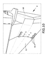
- Figure 10 shows the detailed view of the attachment.
- the attachment of the spreader structure (9) with the upper structure (1) is height adjustable.
- said attachment is by means of four height adjustable attachment points.
- Both the upper structure (1) and the spreader structure (9) are attached with the backhoe machine.
- the upper structure (1) is attached with the backhoe machine by means of attachment bars (16) and (17) and by means of the central frame (8).
- the bar (16) extends from the inner protection and attachment support (6.1) of the caterpillar track (6) to the protection support (20.1) of the left caterpillar track (20).
- the bar (17) extends from the inner protection and attachment support (7.1) of the caterpillar track (7) to the protection support (20.1) of the right caterpillar track (20).
- the spreader structure is attached in an articulated manner with the backhoe machine by means of the bars (18) and (19), extending from each section of the arrowhead-shaped spreader structure (9) to the inner support and protection (20.1) of each caterpillar track (20) of the backhoe machine.
- the first portion (10) of the spreader structure (9) is attached by means of the bars (18) and (19) with the inner support and protection (20.1) of the left caterpillar track (20) of the backhoe machine
- the second portion (11) of the spreader structure (9) is attached by means of the bars (18) and (19) with the inner support and protection (20.1) of the right caterpillar track (20) of the backhoe machine.
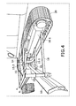
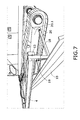
- Constructive details can be observed in Figures 4 , 5 and 7 .
- Figure 2 shows the height adjustable front point (12) for adjusting the height of the spreader structure (9) with respect to the upper structure (1) comprising clamp-like parts (2.1) fixed or welded on the flanges of the front beam (2), there being arranged an adjusting cylinder (12.1), going through the clamps (2.1) and attached at its lower end on the tip of the arrow of the spreader structure and having perforations through which a bolt (12.2) can be introduced.
- an adjusting cylinder (12.1) going through the clamps (2.1) and attached at its lower end on the tip of the arrow of the spreader structure and having perforations through which a bolt (12.2) can be introduced.
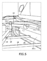
- Figures 4 and 5 show the constructive details of the intermediate adjustment means (14) and (15), among others.
- the intermediate adjustment means (15) comprises a bushing or hollow element (15.1) attached to the beam (16) or (17), inside which there runs a slidable element (15.2) that is perforated and attached at its lower end on the spreader structure (9)
- the intermediate adjustment means (14) comprises a bushing or hollow element (14.1) attached to the frame (8), inside which there runs a slidable element (14.2) that is perforated and attached at its lower end on the spreader structure (9).
- the height adjustable rear element (13) for adjusting the height of the spreader structure with respect to the upper structure (1) also comprises a bushing or hollow element (13.1) attached to the rear end of the side beam (4) or (5), inside which there runs a slidable element (13.2) that is perforated and attached at its lower end on the spreader structure (9).
- the side caterpillar tracks (6) and (7) of the implement are hydraulically actuated from the backhoe to which the caterpillar tracks are attached by means of conduits (25) and (26), respectively, starting at the backhoe and reaching the caterpillar tracks (6) and (7).
- Figure 10 shows a detailed view of the attachment between the two portions (10) and (11) comprised by the spreader structure (9), where the first portion (10) in addition to comprising an entire side also comprises the tip of the structure, being attached with the portion (11) by means of screws (10.1), this attachment being able to be in another form.
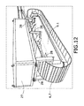
- Figures 11 and 12 show two views of a possible embodiment of a counterweight for the implement.
- the counterweight aims to prevent the implement from being lifted up in response to the thrust of the backhoe machine and the resistance offered by the material or stones to be spread.
- the counterweight comprises a bin (27) open at the top and supported on the inner structure of each caterpillar track (6) and (7) by means of supports (28) which transmit the weight directly to the inner structure of each caterpillar track.
Landscapes
- Engineering & Computer Science (AREA)
- Mechanical Engineering (AREA)
- Mining & Mineral Resources (AREA)
- Civil Engineering (AREA)
- General Engineering & Computer Science (AREA)
- Structural Engineering (AREA)
- Road Paving Machines (AREA)
- Body Structure For Vehicles (AREA)
Abstract

Description
- As established by the title, the object of the present invention is an implement of a caterpillar track machine for spreading gravels or aggregates, an implement being understood as an additional tool which allows spreading stones, gravels, aggregates, ballasts or any other spreadable material when assembled on a caterpillar track-type machine such as backhoes.
- The present invention is characterized by the special constructive features of the implement which, on one hand, allow easy assembly and disassembly on/from a caterpillar track-type machine; it has certain measurements allowing transport in a conventional trailer or truck, in addition to enabling the unloading and subsequent assembly thereof by means of the backhoe machine to which it is attached and with which it works.
- In addition to said operative advantages, a more than significant increase in the performance and speed of spreading gravels, aggregates and the like is obtained.
- Therefore, the present invention is comprised within the field of machines for spreading gravels or aggregates or the like, as well as within the scope of implements for attachments that can be assembled in excavator machines.
- The aggregate and fine gravel spreading machine described in the utility model with application number
ES9200018U ES 1019816U - Said utility model discloses an improved aggregate and fine gravel spreading machine of the types intended for being used, by means of the appropriate towing thereof, to distribute the aggregates and fine gravels by means of the towing thereof by a conventional vehicle, having skid wheels, characterized in that it is provided with a hydraulic motor (1), a drive cylinder (2) for driving the belt, a support bearing (3) for the drive cylinder, an idler cylinder (4) for the belt, and a conveyor belt band (5). Furthermore, it has a container (14) for storing the aggregate which has a product outlet (15), having a towing hitch (16).
- The operation and performance of said machine is limited due to the fact that it is designed for spreading fine gravels and the like from a container assembled on the machine itself. This is because the container for the fine gravel has a limited volume, in addition to entailing an additional load for transport.
- Now, what is sought is to enable spreading gravels or aggregates previously arranged on the ground in a uniform, quick and height adjustable manner, with high performance and great capacity for handling large volumes of material to be spread, developing for these purposes a machine such as that described below and the essential features of which are included in
claim 1. - The object of the present invention is an implement of a caterpillar track machine for spreading gravels or aggregates comprising:
- Two laterally arranged caterpillar tracks having in their inner face protection and support means for
- An upper structure which provides support to
- An arrowhead-shaped spreader structure arranged in the lower portion with respect to the upper structure
- Attachment means for attaching both the upper structure and the spreader structure with the machine on which the implement is to be assembled.
- Adjustment means for adjusting the relative height of the spreader structure with respect to the upper structure, and therefore the level or height at which the material to be spread is to be left.
- Hydraulic actuating means.
- The attachment of the spreader structure with the upper structure is height adjustable by means of several height adjustable attachment points, being able to have one front attachment point, another rear attachment point, and one or several intermediate attachment points.
- Additionally, and in order to reinforce the structural stability of the assembly, the upper structure is attached by means of beams or bars extending from the upper structure to the backhoe machine. The spreader structure also has several bars attached in an articulated manner between said structure and the backhoe machine.
- The attachment bars between the different structures, the upper structure, the spreader structure, and between the preceding structures and the backhoe machine are articulated attachments allowing a certain play and clearance, preventing a stiff structure or frame which may be subjected to forces and torques that could break the structure.
- Additionally and complementarily, the implement can have counterweights arranged on a portion of the structure. Said counterweights aim to prevent the implement from being lifted up in response to the thrust force of the backhoe and the resistance of the gravel to be spread.
- In a possible embodiment, the counterweights are arranged on the side caterpillar tracks of the implement, on a structure fixed to the inner structure of the caterpillar tracks. The counterweights comprise a bin open at the top that can be filled with the actual stones or ballasts to be spread.
- In addition to easy transport, the implement can be assembled and disassembled as a result of its structural features. The measurements thereof allow transport in a conventional trailer or truck and both unloading and assembly are performed by means of the backhoe to which it is attached and with which it works.
- In practice, first the backhoe arrives at the work site, if it is not already there, and the implements are unloaded and assembled with said backhoe.
- The working speed is 3 or 4 times greater than the means used today, which greatly increases the performance.
- It allows adjusting the height of the gravel layer with greater ease and precision. Furthermore, the quality of the finishing is exceptional. Complete uniformity in the gravel layer is achieved.
- To complement the description that is being made and for the purpose of aiding to better understand the features of the invention according to a preferred practical embodiment thereof, a set of drawings is attached as an integral part of said description in which the following has been depicted with an illustrative and non-limiting character.
-
Figure 1 shows a plan view of the implement object of the invention attached in the front portion of a partially shown backhoe machine. -
Figure 2 shows a detailed view of the height adjustment means arranged in the front of the gravel spreader structure. -
Figure 3 shows a front view of the assembly in which several details can be seen. -
Figure 4 shows the attachment of the implement with the backhoe machine in one of its flanks. -
Figure 5 shows a detailed view of the side attachment of the spreader structure with the backhoe machine. -
Figure 6 shows a detailed view of the attachment of the upper structure of the implement with the backhoe machine. -
Figure 7 shows another side view of the implement in its attachment with the backhoe machine. -
Figure 8 shows a detailed view of the front of the implement in one of its sides where constructive features can be seen. -
Figure 9 shows a top view of the side front end of the implement. -
Figure 10 shows the arrowhead of the spreader structure. -
Figure 11 shows a view of a counterweight arranged on a caterpillar track of the implement. -
Figure 12 shows a perspective view of the counterweight arranged on one of the caterpillar tracks. - A preferred embodiment of the proposed invention is described below in view of the drawings.
-
Figure 1 shows a top plan view of the implement attached with a caterpillar track type machine or backhoe machine that has been partially depicted. - Almost all the constructive elements shown in this figure depict the elements which are part of the implement and which are then shown in detail in the remaining figures.
- The implement of a caterpillar track machine for spreading gravels or aggregates is characterized in that it comprises:
- Two laterally arranged caterpillar tracks (6) and (7) having in their inner face protection and support means for
- An upper structure (1) which provides support to
- An arrowhead-shaped spreader structure (9) arranged in the lower portion with respect to the upper structure and it is responsible for separating the gravel on both sides, also for leaving it at a certain height with respect to the ground.
- Attachment means for attaching both the upper structure and the spreader structure with the machine on which the implement is to be assembled.
- Adjustment means for adjusting the relative height of the spreader structure with respect to the upper structure, and therefore the desired level or height at which the material to be spread is to be left.
- Hydraulic actuating means
-
Figure 1 shows the two caterpillar tracks (6) and (7) arranged on both sides of the implement, each of the caterpillar tracks (6) and (7) has in its inner face protections (6.1) and (7.1) on which the upper structure (1) is supported in the front thereof. - The upper structure (1) is formed by:
- a first forward front beam (2),
- a second front beam (3) parallel to preceding beam,
- two side stringers (4) and (5) which are attached at their front portion to the ends of the beams (2) and (3), said attachment ends being fixed and assembled on the inner faces of the caterpillar tracks (6) and (7)
- a central frame (8) extending from the second front beam (3) to the front of the excavator.
- The spreader structure (9) is arrowhead-shaped and in a possible embodiment comprises a first portion (10) or side flank of the arrowhead which further comprises the tip of the arrow, being attached to a second portion (11) at the end of this second portion.
Figure 10 shows the detailed view of the attachment. - The attachment of the spreader structure (9) with the upper structure (1) is height adjustable. In a possible embodiment, said attachment is by means of four height adjustable attachment points.
- A height adjustable front attachment point (12) arranged on the front beam (1)
- A height adjustable rear attachment point (13) arranged on the rear end of the side flanks (4) and (5)
- Two height adjustable intermediate attachment points (14) and (15), where the height adjustable attachment point (15) is on the central frame (8), whereas the height adjustable intermediate attachment point (16) is on the attachment bar (16), (17) between the side caterpillar tracks (6) and (7) of the implement, with the caterpillar tracks (20) of the backhoe.
- Both the upper structure (1) and the spreader structure (9) are attached with the backhoe machine.
- The upper structure (1) is attached with the backhoe machine by means of attachment bars (16) and (17) and by means of the central frame (8). The bar (16) extends from the inner protection and attachment support (6.1) of the caterpillar track (6) to the protection support (20.1) of the left caterpillar track (20). On the other hand, the bar (17) extends from the inner protection and attachment support (7.1) of the caterpillar track (7) to the protection support (20.1) of the right caterpillar track (20).
- Additionally, and as a structural reinforcement measure, it further has:
- bars (21) and (22) attached in an articulated manner between the bars (16) and (17) and the central frame (8). This can be seen in detail in
Figures 6 and9 . - bars (23) and (24) attached in an articulated manner at their ends with the side stringer (4) and (5) and with the bars (16) and (17), respectively, as seen in detail in
Figure 8 . - The spreader structure is attached in an articulated manner with the backhoe machine by means of the bars (18) and (19), extending from each section of the arrowhead-shaped spreader structure (9) to the inner support and protection (20.1) of each caterpillar track (20) of the backhoe machine.
- Therefore, the first portion (10) of the spreader structure (9) is attached by means of the bars (18) and (19) with the inner support and protection (20.1) of the left caterpillar track (20) of the backhoe machine, whereas the second portion (11) of the spreader structure (9) is attached by means of the bars (18) and (19) with the inner support and protection (20.1) of the right caterpillar track (20) of the backhoe machine. Constructive details can be observed in
Figures 4 ,5 and7 . -
Figure 2 shows the height adjustable front point (12) for adjusting the height of the spreader structure (9) with respect to the upper structure (1) comprising clamp-like parts (2.1) fixed or welded on the flanges of the front beam (2), there being arranged an adjusting cylinder (12.1), going through the clamps (2.1) and attached at its lower end on the tip of the arrow of the spreader structure and having perforations through which a bolt (12.2) can be introduced. -
Figures 4 and5 show the constructive details of the intermediate adjustment means (14) and (15), among others. - The intermediate adjustment means (15) comprises a bushing or hollow element (15.1) attached to the beam (16) or (17), inside which there runs a slidable element (15.2) that is perforated and attached at its lower end on the spreader structure (9)
- The intermediate adjustment means (14) comprises a bushing or hollow element (14.1) attached to the frame (8), inside which there runs a slidable element (14.2) that is perforated and attached at its lower end on the spreader structure (9).
- The height adjustable rear element (13) for adjusting the height of the spreader structure with respect to the upper structure (1) also comprises a bushing or hollow element (13.1) attached to the rear end of the side beam (4) or (5), inside which there runs a slidable element (13.2) that is perforated and attached at its lower end on the spreader structure (9).
- The side caterpillar tracks (6) and (7) of the implement are hydraulically actuated from the backhoe to which the caterpillar tracks are attached by means of conduits (25) and (26), respectively, starting at the backhoe and reaching the caterpillar tracks (6) and (7).
- Finally,
Figure 10 shows a detailed view of the attachment between the two portions (10) and (11) comprised by the spreader structure (9), where the first portion (10) in addition to comprising an entire side also comprises the tip of the structure, being attached with the portion (11) by means of screws (10.1), this attachment being able to be in another form. -
Figures 11 and12 show two views of a possible embodiment of a counterweight for the implement. The counterweight aims to prevent the implement from being lifted up in response to the thrust of the backhoe machine and the resistance offered by the material or stones to be spread. - The counterweight comprises a bin (27) open at the top and supported on the inner structure of each caterpillar track (6) and (7) by means of supports (28) which transmit the weight directly to the inner structure of each caterpillar track.
- Having sufficiently described the nature of the present invention as well as the manner of putting it into practice, it must be stated that it could be carried out to practice within the essential features thereof in other embodiments differing in detail from that indicated by way of example, and such embodiments will also be covered by the protection sought provided that the fundamental principle thereof is not altered, changed or modified.
Claims (15)
- An implement of a caterpillar track machine for spreading gravels or aggregates, characterized in that it comprises:- Two laterally arranged caterpillar tracks (6) and (7) having in their inner face protection and support means (6.1) and (7.1) for- An upper structure (1) which provides support to- An arrowhead-shaped spreader structure (9) arranged in the lower portion with respect to the upper structure- Attachment means for attaching both the upper structure and the spreader structure with the machine on which the implement is to be assembled- Adjustment means for adjusting the relative height of the spreader structure (9) with respect to the upper structure (1), and therefore the level or height at which the material to be spread is to be left- Hydraulic actuating means.
- The implement of a caterpillar track machine for spreading gravels or aggregates according to claim 1, characterized in that the upper structure (1) is formed by:- a first forward front beam (2),- a second front beam (3) parallel to the preceding beam,- two side stringers (4) and (5) which are attached at their front portion to the ends of the beams (2) and (3), said attachment ends being fixed and assembled on the inner faces of the caterpillar tracks (6) and (7)- a central frame (8) extending from the second front beam (3) to the front of the excavator.
- The implement of a caterpillar track machine for spreading gravels or aggregates according to claim 1, characterized in that the spreader structure (9) is arrowhead-shaped and comprises a first portion (10) or side flank of the arrowhead which further comprises the tip of the arrow, being attached to a second portion (11) at the end of this second portion.
- The implement of a caterpillar track machine for spreading gravels or aggregates according to claim 1, characterized in that the attachment means for attaching the upper structure (1) with the backhoe machine are attachment bars (16) and (17) attached in an articulated manner at their attachment ends with the upper structure (1) and the central frame (8), where the bar (16) extends from the inner protection and attachment support (6.1) of the caterpillar track (6) to the protection support (20.1) of the left caterpillar track (20), whereas the bar (17) extends from the inner protection and attachment support (7.1) of the caterpillar track (7) to the protection support (20.1) of the right caterpillar track (20).
- The implement of a caterpillar track machine for spreading gravels or aggregates according to claim 6, characterized in that additionally, and as a structural reinforcement measure, it further has:- bars (21) and (22) attached in an articulated manner between the bars (16) and (17) and the frame (18)- bars (23) and (24) attached in an articulated manner at their ends between the side stringer (4) and (5) with the bars (16) and (17), respectively, as seen in detail in Figure 8.
- The implement of a caterpillar track machine for spreading gravels or aggregates according to claim 1, characterized in that the spreader structure (9) is attached in an articulated manner by means of the bars (18) and (19), extending from each section of the arrowhead-shaped spreader structure (9) to the inner support and protection (20.1) of each caterpillar track (20) of the backhoe machine.
- The implement of a caterpillar track machine for spreading gravels or aggregates according to claim 2, characterized in that the adjustment means for adjusting the height of the spreader structure (9) with the upper structure (1) comprises four height adjustable attachment points.
- The implement of a caterpillar track machine for spreading gravels or aggregates according to claim 4, characterized in that the height adjustable points are:- A height adjustable front attachment point (12) arranged on the front beam (1)- A height adjustable rear attachment point (13) arranged on the rear end of the side flanks (4) and (5)- Two height adjustable intermediate attachment points (14) and (15), where the height adjustable attachment point (15) is on the central frame (8), whereas the height adjustable intermediate attachment point (16) is on the attachment bar (16), (17) between the side caterpillar tracks (6) and (7) of the implement, with the caterpillar tracks (20) of the backhoe.
- The implement of a caterpillar track machine for spreading gravels or aggregates according to claim 8, characterized in that the height adjustable front point (12) for adjusting the relative height of the spreader structure (9) with respect to the upper structure (1) comprises clamp-like parts (2.1) fixed or welded on the flanges of the front beam (2), there being arranged an adjusting cylinder (12.1), going through the clamps (2.1) and attached at its lower end on the tip of the arrow of the spreader structure and having perforations through which a bolt (12.2) can be introduced.
- The implement of a caterpillar track machine for spreading gravels or aggregates according to claim 8, characterized in that the intermediate adjustment means (15) comprises a bushing or hollow element (15.1) attached to the beam (16) or (17), inside which there runs a slidable element (15.2) that is perforated and attached at its lower end on the spreader structure (9).
- The implement of a caterpillar track machine for spreading gravels or aggregates according to claim 8, characterized in that the intermediate adjustment means (14) comprises a bushing or hollow element (14.1) attached to the frame (8), inside which there runs a slidable element (14.2) that is perforated and attached at its lower end on the spreader structure (9).
- The implement of a caterpillar track machine for spreading gravels or aggregates according to claim 8, characterized in that the height adjustable rear element (13) for adjusting the height of the spreader structure with respect to the upper structure (1) comprises a bushing or hollow element (13.1) attached to the rear end of the side beam (4) or (5), inside which there runs a slidable element (13.2) that is perforated and attached at its lower end on the spreader structure (9).
- The implement of a caterpillar track machine for spreading gravels or aggregates according to claim 8, characterized in that the side caterpillar tracks (6) and (7) of the implement are hydraulically actuated from the backhoe to which the caterpillar tracks are attached by means of conduits (25) and (26), respectively, starting at the backhoe and reaching the caterpillar tracks (6) and (7).
- The implement of a caterpillar track machine for spreading gravels or aggregates according to any of the preceding claims, characterized in that it has a counterweight arranged on the implement itself.
- The implement of a caterpillar track machine for spreading gravels or aggregates according to claim 13, characterized in that the counterweight comprises a bin (27) open at the top where heavy material, such as the actual gravel or aggregate, can be kept, one of such bins being arranged above each caterpillar track (6) and (7) and attached to the inner structure of each caterpillar track by means of supports (28).
Priority Applications (2)
| Application Number | Priority Date | Filing Date | Title |
|---|---|---|---|
| EP13382105.8A EP2781656B1 (en) | 2013-03-22 | 2013-03-22 | Implement for a caterpillar track machine for spreading gravels, aggregates or the like |
| ES13382105.8T ES2682760T3 (en) | 2013-03-22 | 2013-03-22 | Caterpillar machine hoop to extend gravels, aggregates or the like |
Applications Claiming Priority (1)
| Application Number | Priority Date | Filing Date | Title |
|---|---|---|---|
| EP13382105.8A EP2781656B1 (en) | 2013-03-22 | 2013-03-22 | Implement for a caterpillar track machine for spreading gravels, aggregates or the like |
Publications (2)
| Publication Number | Publication Date |
|---|---|
| EP2781656A1 true EP2781656A1 (en) | 2014-09-24 |
| EP2781656B1 EP2781656B1 (en) | 2018-05-09 |
Family
ID=48083087
Family Applications (1)
| Application Number | Title | Priority Date | Filing Date |
|---|---|---|---|
| EP13382105.8A Active EP2781656B1 (en) | 2013-03-22 | 2013-03-22 | Implement for a caterpillar track machine for spreading gravels, aggregates or the like |
Country Status (2)
| Country | Link |
|---|---|
| EP (1) | EP2781656B1 (en) |
| ES (1) | ES2682760T3 (en) |
Cited By (1)
| Publication number | Priority date | Publication date | Assignee | Title |
|---|---|---|---|---|
| CN116377802A (en) * | 2023-05-30 | 2023-07-04 | 中部高速公路管理(山西)有限公司 | Local filling pressure equipment for road maintenance |
Citations (6)
| Publication number | Priority date | Publication date | Assignee | Title |
|---|---|---|---|---|
| US1956007A (en) * | 1932-11-12 | 1934-04-24 | Plant Choate Mfg Co Inc | Earth moving device |
| US2698491A (en) * | 1949-11-18 | 1955-01-04 | George H Felt | Bulldozer blade stabilizing attachment |
| FR1455369A (en) * | 1965-08-31 | 1966-04-01 | Routiere Soc Gen | Earth moving device |
| US4136992A (en) * | 1977-02-11 | 1979-01-30 | Gunnar Olsson | Method of stabilizing ground of low bearing capacity, and a stabilizing unit for carrying out the method |
| ES1019816U (en) | 1992-01-07 | 1992-05-01 | Lopez Ortiz Vicente | Paver machine graded aggregates and gravels perfected. (Machine-translation by Google Translate, not legally binding) |
| WO1995026445A1 (en) * | 1994-03-29 | 1995-10-05 | Yves Blandin | Levelling blade with vibrating shoes for making road embankments |
-
2013
- 2013-03-22 EP EP13382105.8A patent/EP2781656B1/en active Active
- 2013-03-22 ES ES13382105.8T patent/ES2682760T3/en active Active
Patent Citations (6)
| Publication number | Priority date | Publication date | Assignee | Title |
|---|---|---|---|---|
| US1956007A (en) * | 1932-11-12 | 1934-04-24 | Plant Choate Mfg Co Inc | Earth moving device |
| US2698491A (en) * | 1949-11-18 | 1955-01-04 | George H Felt | Bulldozer blade stabilizing attachment |
| FR1455369A (en) * | 1965-08-31 | 1966-04-01 | Routiere Soc Gen | Earth moving device |
| US4136992A (en) * | 1977-02-11 | 1979-01-30 | Gunnar Olsson | Method of stabilizing ground of low bearing capacity, and a stabilizing unit for carrying out the method |
| ES1019816U (en) | 1992-01-07 | 1992-05-01 | Lopez Ortiz Vicente | Paver machine graded aggregates and gravels perfected. (Machine-translation by Google Translate, not legally binding) |
| WO1995026445A1 (en) * | 1994-03-29 | 1995-10-05 | Yves Blandin | Levelling blade with vibrating shoes for making road embankments |
Cited By (2)
| Publication number | Priority date | Publication date | Assignee | Title |
|---|---|---|---|---|
| CN116377802A (en) * | 2023-05-30 | 2023-07-04 | 中部高速公路管理(山西)有限公司 | Local filling pressure equipment for road maintenance |
| CN116377802B (en) * | 2023-05-30 | 2023-08-15 | 中部高速公路管理(山西)有限公司 | Local filling pressure equipment for road maintenance |
Also Published As
| Publication number | Publication date |
|---|---|
| EP2781656B1 (en) | 2018-05-09 |
| ES2682760T3 (en) | 2018-09-21 |
Similar Documents
| Publication | Publication Date | Title |
|---|---|---|
| KR102170608B1 (en) | Excavator bucket and manufacturing method | |
| CN203247618U (en) | Hydraulic spading loading machine | |
| CN112533792A (en) | Vehicle body for truck and truck | |
| DE3920011C2 (en) | ||
| EP2994345B1 (en) | A dump body for a working machine | |
| DE102012210373A1 (en) | mounted compactors | |
| EP2781656B1 (en) | Implement for a caterpillar track machine for spreading gravels, aggregates or the like | |
| US20060243465A1 (en) | Material handling system | |
| US8631594B1 (en) | Variable width screed attachment | |
| US1987928A (en) | Road finishing machine | |
| EP2369065A1 (en) | Self-propelled agricultural work machine, in particular wheeled excavator | |
| WO2005090122A1 (en) | Device for transporting a construction machine | |
| KR20180094686A (en) | Construction machinery | |
| EP3775405B1 (en) | Lift truck | |
| FI127862B (en) | Multifunctional bucket for a working vehicle | |
| DE334066C (en) | Method and excavator for digging trenches with sloped walls | |
| EP3208386B1 (en) | Device for holding and driving an aggregate for the preparation of dispensed lump material | |
| DE2063511A1 (en) | Hydraulically operated excavator | |
| US1215044A (en) | Road-leveling machine. | |
| RU2139979C1 (en) | Single-bucket front-end loader | |
| US542375A (en) | scoles | |
| DE1484713A1 (en) | Dredging device for attachment to tractors or similar transport vehicles | |
| AU768356B2 (en) | Grader device | |
| US20200224375A1 (en) | Method and apparatus for distributing cement | |
| US20090194304A1 (en) | Grading Attachment for Skid-Steer Vehicle |
Legal Events
| Date | Code | Title | Description |
|---|---|---|---|
| PUAI | Public reference made under article 153(3) epc to a published international application that has entered the european phase |
Free format text: ORIGINAL CODE: 0009012 |
|
| 17P | Request for examination filed |
Effective date: 20130418 |
|
| AK | Designated contracting states |
Kind code of ref document: A1 Designated state(s): AL AT BE BG CH CY CZ DE DK EE ES FI FR GB GR HR HU IE IS IT LI LT LU LV MC MK MT NL NO PL PT RO RS SE SI SK SM TR |
|
| AX | Request for extension of the european patent |
Extension state: BA ME |
|
| RBV | Designated contracting states (corrected) |
Designated state(s): AL AT BE BG CH CY CZ DE DK EE ES FI FR GB GR HR HU IE IS IT LI LT LU LV MC MK MT NL NO PL PT RO RS SE SI SK SM TR |
|
| GRAP | Despatch of communication of intention to grant a patent |
Free format text: ORIGINAL CODE: EPIDOSNIGR1 |
|
| STAA | Information on the status of an ep patent application or granted ep patent |
Free format text: STATUS: GRANT OF PATENT IS INTENDED |
|
| INTG | Intention to grant announced |
Effective date: 20180219 |
|
| GRAS | Grant fee paid |
Free format text: ORIGINAL CODE: EPIDOSNIGR3 |
|
| GRAA | (expected) grant |
Free format text: ORIGINAL CODE: 0009210 |
|
| STAA | Information on the status of an ep patent application or granted ep patent |
Free format text: STATUS: THE PATENT HAS BEEN GRANTED |
|
| AK | Designated contracting states |
Kind code of ref document: B1 Designated state(s): AL AT BE BG CH CY CZ DE DK EE ES FI FR GB GR HR HU IE IS IT LI LT LU LV MC MK MT NL NO PL PT RO RS SE SI SK SM TR |
|
| REG | Reference to a national code |
Ref country code: GB Ref legal event code: FG4D |
|
| REG | Reference to a national code |
Ref country code: CH Ref legal event code: EP Ref country code: AT Ref legal event code: REF Ref document number: 997667 Country of ref document: AT Kind code of ref document: T Effective date: 20180515 |
|
| REG | Reference to a national code |
Ref country code: IE Ref legal event code: FG4D |
|
| REG | Reference to a national code |
Ref country code: DE Ref legal event code: R096 Ref document number: 602013037169 Country of ref document: DE |
|
| REG | Reference to a national code |
Ref country code: NL Ref legal event code: MP Effective date: 20180509 |
|
| REG | Reference to a national code |
Ref country code: ES Ref legal event code: FG2A Ref document number: 2682760 Country of ref document: ES Kind code of ref document: T3 Effective date: 20180921 |
|
| REG | Reference to a national code |
Ref country code: LT Ref legal event code: MG4D |
|
| PG25 | Lapsed in a contracting state [announced via postgrant information from national office to epo] |
Ref country code: LT Free format text: LAPSE BECAUSE OF FAILURE TO SUBMIT A TRANSLATION OF THE DESCRIPTION OR TO PAY THE FEE WITHIN THE PRESCRIBED TIME-LIMIT Effective date: 20180509 Ref country code: BG Free format text: LAPSE BECAUSE OF FAILURE TO SUBMIT A TRANSLATION OF THE DESCRIPTION OR TO PAY THE FEE WITHIN THE PRESCRIBED TIME-LIMIT Effective date: 20180809 Ref country code: NO Free format text: LAPSE BECAUSE OF FAILURE TO SUBMIT A TRANSLATION OF THE DESCRIPTION OR TO PAY THE FEE WITHIN THE PRESCRIBED TIME-LIMIT Effective date: 20180809 Ref country code: SE Free format text: LAPSE BECAUSE OF FAILURE TO SUBMIT A TRANSLATION OF THE DESCRIPTION OR TO PAY THE FEE WITHIN THE PRESCRIBED TIME-LIMIT Effective date: 20180509 Ref country code: FI Free format text: LAPSE BECAUSE OF FAILURE TO SUBMIT A TRANSLATION OF THE DESCRIPTION OR TO PAY THE FEE WITHIN THE PRESCRIBED TIME-LIMIT Effective date: 20180509 |
|
| PG25 | Lapsed in a contracting state [announced via postgrant information from national office to epo] |
Ref country code: HR Free format text: LAPSE BECAUSE OF FAILURE TO SUBMIT A TRANSLATION OF THE DESCRIPTION OR TO PAY THE FEE WITHIN THE PRESCRIBED TIME-LIMIT Effective date: 20180509 Ref country code: LV Free format text: LAPSE BECAUSE OF FAILURE TO SUBMIT A TRANSLATION OF THE DESCRIPTION OR TO PAY THE FEE WITHIN THE PRESCRIBED TIME-LIMIT Effective date: 20180509 Ref country code: RS Free format text: LAPSE BECAUSE OF FAILURE TO SUBMIT A TRANSLATION OF THE DESCRIPTION OR TO PAY THE FEE WITHIN THE PRESCRIBED TIME-LIMIT Effective date: 20180509 Ref country code: GR Free format text: LAPSE BECAUSE OF FAILURE TO SUBMIT A TRANSLATION OF THE DESCRIPTION OR TO PAY THE FEE WITHIN THE PRESCRIBED TIME-LIMIT Effective date: 20180810 Ref country code: NL Free format text: LAPSE BECAUSE OF FAILURE TO SUBMIT A TRANSLATION OF THE DESCRIPTION OR TO PAY THE FEE WITHIN THE PRESCRIBED TIME-LIMIT Effective date: 20180509 |
|
| REG | Reference to a national code |
Ref country code: AT Ref legal event code: MK05 Ref document number: 997667 Country of ref document: AT Kind code of ref document: T Effective date: 20180509 |
|
| PG25 | Lapsed in a contracting state [announced via postgrant information from national office to epo] |
Ref country code: SK Free format text: LAPSE BECAUSE OF FAILURE TO SUBMIT A TRANSLATION OF THE DESCRIPTION OR TO PAY THE FEE WITHIN THE PRESCRIBED TIME-LIMIT Effective date: 20180509 Ref country code: RO Free format text: LAPSE BECAUSE OF FAILURE TO SUBMIT A TRANSLATION OF THE DESCRIPTION OR TO PAY THE FEE WITHIN THE PRESCRIBED TIME-LIMIT Effective date: 20180509 Ref country code: CZ Free format text: LAPSE BECAUSE OF FAILURE TO SUBMIT A TRANSLATION OF THE DESCRIPTION OR TO PAY THE FEE WITHIN THE PRESCRIBED TIME-LIMIT Effective date: 20180509 Ref country code: PL Free format text: LAPSE BECAUSE OF FAILURE TO SUBMIT A TRANSLATION OF THE DESCRIPTION OR TO PAY THE FEE WITHIN THE PRESCRIBED TIME-LIMIT Effective date: 20180509 Ref country code: DK Free format text: LAPSE BECAUSE OF FAILURE TO SUBMIT A TRANSLATION OF THE DESCRIPTION OR TO PAY THE FEE WITHIN THE PRESCRIBED TIME-LIMIT Effective date: 20180509 Ref country code: EE Free format text: LAPSE BECAUSE OF FAILURE TO SUBMIT A TRANSLATION OF THE DESCRIPTION OR TO PAY THE FEE WITHIN THE PRESCRIBED TIME-LIMIT Effective date: 20180509 Ref country code: AT Free format text: LAPSE BECAUSE OF FAILURE TO SUBMIT A TRANSLATION OF THE DESCRIPTION OR TO PAY THE FEE WITHIN THE PRESCRIBED TIME-LIMIT Effective date: 20180509 |
|
| REG | Reference to a national code |
Ref country code: DE Ref legal event code: R097 Ref document number: 602013037169 Country of ref document: DE |
|
| PG25 | Lapsed in a contracting state [announced via postgrant information from national office to epo] |
Ref country code: IT Free format text: LAPSE BECAUSE OF FAILURE TO SUBMIT A TRANSLATION OF THE DESCRIPTION OR TO PAY THE FEE WITHIN THE PRESCRIBED TIME-LIMIT Effective date: 20180509 Ref country code: SM Free format text: LAPSE BECAUSE OF FAILURE TO SUBMIT A TRANSLATION OF THE DESCRIPTION OR TO PAY THE FEE WITHIN THE PRESCRIBED TIME-LIMIT Effective date: 20180509 |
|
| PLBE | No opposition filed within time limit |
Free format text: ORIGINAL CODE: 0009261 |
|
| STAA | Information on the status of an ep patent application or granted ep patent |
Free format text: STATUS: NO OPPOSITION FILED WITHIN TIME LIMIT |
|
| 26N | No opposition filed |
Effective date: 20190212 |
|
| PG25 | Lapsed in a contracting state [announced via postgrant information from national office to epo] |
Ref country code: SI Free format text: LAPSE BECAUSE OF FAILURE TO SUBMIT A TRANSLATION OF THE DESCRIPTION OR TO PAY THE FEE WITHIN THE PRESCRIBED TIME-LIMIT Effective date: 20180509 |
|
| REG | Reference to a national code |
Ref country code: DE Ref legal event code: R119 Ref document number: 602013037169 Country of ref document: DE |
|
| PG25 | Lapsed in a contracting state [announced via postgrant information from national office to epo] |
Ref country code: MC Free format text: LAPSE BECAUSE OF FAILURE TO SUBMIT A TRANSLATION OF THE DESCRIPTION OR TO PAY THE FEE WITHIN THE PRESCRIBED TIME-LIMIT Effective date: 20180509 |
|
| REG | Reference to a national code |
Ref country code: CH Ref legal event code: PL |
|
| GBPC | Gb: european patent ceased through non-payment of renewal fee |
Effective date: 20190322 |
|
| PG25 | Lapsed in a contracting state [announced via postgrant information from national office to epo] |
Ref country code: LU Free format text: LAPSE BECAUSE OF NON-PAYMENT OF DUE FEES Effective date: 20190322 Ref country code: AL Free format text: LAPSE BECAUSE OF FAILURE TO SUBMIT A TRANSLATION OF THE DESCRIPTION OR TO PAY THE FEE WITHIN THE PRESCRIBED TIME-LIMIT Effective date: 20180509 |
|
| REG | Reference to a national code |
Ref country code: BE Ref legal event code: MM Effective date: 20190331 |
|
| PG25 | Lapsed in a contracting state [announced via postgrant information from national office to epo] |
Ref country code: LI Free format text: LAPSE BECAUSE OF NON-PAYMENT OF DUE FEES Effective date: 20190331 Ref country code: DE Free format text: LAPSE BECAUSE OF NON-PAYMENT OF DUE FEES Effective date: 20191001 Ref country code: CH Free format text: LAPSE BECAUSE OF NON-PAYMENT OF DUE FEES Effective date: 20190331 Ref country code: IE Free format text: LAPSE BECAUSE OF NON-PAYMENT OF DUE FEES Effective date: 20190322 Ref country code: GB Free format text: LAPSE BECAUSE OF NON-PAYMENT OF DUE FEES Effective date: 20190322 |
|
| PG25 | Lapsed in a contracting state [announced via postgrant information from national office to epo] |
Ref country code: BE Free format text: LAPSE BECAUSE OF NON-PAYMENT OF DUE FEES Effective date: 20190331 |
|
| PG25 | Lapsed in a contracting state [announced via postgrant information from national office to epo] |
Ref country code: TR Free format text: LAPSE BECAUSE OF FAILURE TO SUBMIT A TRANSLATION OF THE DESCRIPTION OR TO PAY THE FEE WITHIN THE PRESCRIBED TIME-LIMIT Effective date: 20180509 |
|
| PG25 | Lapsed in a contracting state [announced via postgrant information from national office to epo] |
Ref country code: PT Free format text: LAPSE BECAUSE OF FAILURE TO SUBMIT A TRANSLATION OF THE DESCRIPTION OR TO PAY THE FEE WITHIN THE PRESCRIBED TIME-LIMIT Effective date: 20180910 Ref country code: MT Free format text: LAPSE BECAUSE OF NON-PAYMENT OF DUE FEES Effective date: 20190322 |
|
| PG25 | Lapsed in a contracting state [announced via postgrant information from national office to epo] |
Ref country code: CY Free format text: LAPSE BECAUSE OF FAILURE TO SUBMIT A TRANSLATION OF THE DESCRIPTION OR TO PAY THE FEE WITHIN THE PRESCRIBED TIME-LIMIT Effective date: 20180509 |
|
| PG25 | Lapsed in a contracting state [announced via postgrant information from national office to epo] |
Ref country code: IS Free format text: LAPSE BECAUSE OF FAILURE TO SUBMIT A TRANSLATION OF THE DESCRIPTION OR TO PAY THE FEE WITHIN THE PRESCRIBED TIME-LIMIT Effective date: 20180909 |
|
| PG25 | Lapsed in a contracting state [announced via postgrant information from national office to epo] |
Ref country code: HU Free format text: LAPSE BECAUSE OF FAILURE TO SUBMIT A TRANSLATION OF THE DESCRIPTION OR TO PAY THE FEE WITHIN THE PRESCRIBED TIME-LIMIT; INVALID AB INITIO Effective date: 20130322 |
|
| PG25 | Lapsed in a contracting state [announced via postgrant information from national office to epo] |
Ref country code: MK Free format text: LAPSE BECAUSE OF FAILURE TO SUBMIT A TRANSLATION OF THE DESCRIPTION OR TO PAY THE FEE WITHIN THE PRESCRIBED TIME-LIMIT Effective date: 20180509 |
|
| PGFP | Annual fee paid to national office [announced via postgrant information from national office to epo] |
Ref country code: FR Payment date: 20260318 Year of fee payment: 14 |
|
| PGFP | Annual fee paid to national office [announced via postgrant information from national office to epo] |
Ref country code: ES Payment date: 20260407 Year of fee payment: 14 |