EP2779426A2 - Generatorarchitektur mit PMG-Erreger und rotierendem Hauptfeld-Leistungswandler - Google Patents
Generatorarchitektur mit PMG-Erreger und rotierendem Hauptfeld-Leistungswandler Download PDFInfo
- Publication number
- EP2779426A2 EP2779426A2 EP14159210.5A EP14159210A EP2779426A2 EP 2779426 A2 EP2779426 A2 EP 2779426A2 EP 14159210 A EP14159210 A EP 14159210A EP 2779426 A2 EP2779426 A2 EP 2779426A2
- Authority
- EP
- European Patent Office
- Prior art keywords
- main field
- winding
- generator
- rotating
- current
- Prior art date
- Legal status (The legal status is an assumption and is not a legal conclusion. Google has not performed a legal analysis and makes no representation as to the accuracy of the status listed.)
- Withdrawn
Links
Images
Classifications
-
- H—ELECTRICITY
- H02—GENERATION; CONVERSION OR DISTRIBUTION OF ELECTRIC POWER
- H02K—DYNAMO-ELECTRIC MACHINES
- H02K19/00—Synchronous motors or generators
- H02K19/16—Synchronous generators
- H02K19/36—Structural association of synchronous generators with auxiliary electric devices influencing the characteristic of the generator or controlling the generator, e.g. with impedances or switches
- H02K19/365—Structural association of synchronous generators with auxiliary electric devices influencing the characteristic of the generator or controlling the generator, e.g. with impedances or switches with a voltage regulator
-
- H—ELECTRICITY
- H02—GENERATION; CONVERSION OR DISTRIBUTION OF ELECTRIC POWER
- H02P—CONTROL OR REGULATION OF ELECTRIC MOTORS, ELECTRIC GENERATORS OR DYNAMO-ELECTRIC CONVERTERS; CONTROLLING TRANSFORMERS, REACTORS OR CHOKE COILS
- H02P9/00—Arrangements for controlling electric generators for the purpose of obtaining a desired output
- H02P9/48—Arrangements for obtaining a constant output value at varying speed of the generator, e.g. on vehicle
-
- H—ELECTRICITY
- H02—GENERATION; CONVERSION OR DISTRIBUTION OF ELECTRIC POWER
- H02P—CONTROL OR REGULATION OF ELECTRIC MOTORS, ELECTRIC GENERATORS OR DYNAMO-ELECTRIC CONVERTERS; CONTROLLING TRANSFORMERS, REACTORS OR CHOKE COILS
- H02P9/00—Arrangements for controlling electric generators for the purpose of obtaining a desired output
- H02P9/14—Arrangements for controlling electric generators for the purpose of obtaining a desired output by variation of field
- H02P9/26—Arrangements for controlling electric generators for the purpose of obtaining a desired output by variation of field using discharge tubes or semiconductor devices
- H02P9/30—Arrangements for controlling electric generators for the purpose of obtaining a desired output by variation of field using discharge tubes or semiconductor devices using semiconductor devices
Definitions
- generators convert mechanical energy to electrical energy via the interaction of rotating magnetic fields and coils of wire.
- a multitude of generator architectures have been developed with various means of providing interaction magnetic fields and coils of wire.
- PMG permanent magnet generator
- Another type of generator supplies current through a coil to generate the desired magnetic field, which is rotated via the mechanical energy supplied by a prime mover, such that a rotating magnetic field is created that interacts with stator coils to provide an output voltage.
- the output voltage supplied by the PMG depends only on the magnitude of the mechanical energy supplied by the prime mover.
- the output voltage of the generator can be regulated by varying the current supplied to the field coil.
- the latter example known as a wound field synchronous machine, is widely utilized.
- permanent magnets offer advantages over excitation provided via an exciter winding. The key drawback to permanent magnets is that magnetic flux provided by the permanent magnets is constant, unlike an exciter coil in which the magnetic flux can be regulated by increasing or decreasing the current through the exciter coil. Permanent magnets would therefore be useful in a number of generator applications if a form of regulation could be introduced.
- a generator includes a stationary portion and a rotating portion.
- the stationary portion includes a permanent magnet and a main armature winding.
- the rotating portion includes a main field winding and a main field rotating power converter that regulates current through the main field winding.
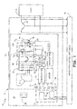
- FIG. 1 is a circuit diagram of electric power generation and distribution system 10 according to an embodiment of the present invention.
- System 10 includes generator 12, generator control unit (GCU) 14, and load 16.
- Generator 12 is divided into stationary portion 24 and rotating portion 26.
- Stationary portion 24 includes permanent magnet 28, stationary communication module 29, and main armature windings 32.
- Rotating portion 26 includes exciter armature windings 34, rotating communication module 35, rectifier 38, direct current (DC) link capacitor CdcR, DC link bus 40, main field rotating power converter 42, main field winding 44, current sensor 46, demodulator 48, gate drive circuit 50, modulator 52, drive circuit 54, and internal power supply (IPS) 56
- DC direct current
- IPS internal power supply
- GCU 14 Generator control unit (GCU) 14 is responsible for regulation and protection of generator 12. Regulation refers to maintaining the output voltage of generator 12 provided by main armature winding 32 at a desired level. Protection refers, at least in part, to preventing faults such as overvoltage faults from damaging generator 12 or attached loads 16.
- a typically wound field synchronous generator utilizes an exciter field winding in place of permanent magnets 28 to provide excitation to rotating portion 26. The excitation provided to the exciter field winding can be regulated to control the output voltage generated by main armature winding 32.
- permanent magnet 28 is employed to provide excitation to rotating portion 26. The magnetic flux generated by permanent magnet 28 is constant.
- Rotation of rotating portion 26 causes exciter armature windings 34 to cut through the constant magnetic flux provided by stationary permanent magnet 28, inducing an alternating current voltage on exciter armature winding 34.
- voltage induced by permanent magnet 28 in PMG windings 34 is a function of generator speed, and therefore cannot be regulated by GCU 14.
- the output voltage generated on main armature winding 32 is regulated by controlling the current through main field winding 44 via main field rotating power converter 42.
- Regulation of the output voltage via control of the current supplied to main field winding 44 requires communication of commands/instructions/feedback across the air gap separating stationary portion 24 from rotating portion 26. Likewise, overvoltage protection is provided by communicating commands/instructions across the air gap separating stationary portion 24 from rotating portion 26. As discussed in more detail below, based on the received instructions/commands, main field rotating power converter 42 selectively applies voltage to main field winding 44.
- GCU 14 is connected to monitor the output voltage provided by main armature winding 32 and communicate commands, instructions, and/or feedback to rotating portion 26 of generator 12 via stationary communication module 29.
- Permanent magnet 28 induces a voltage in PMG windings 34 located on rotating portion 26.
- the AC voltage generated on exciter armature winding 34 is rectified by rectifier 38 and DC link capacitor CdcR to a DC voltage that is supplied to main field rotating power converter 42 via DC link bus 40.
- rectifier 38 is a passive rectifier comprised of a plurality of bridge-connected diodes.
- rectifier 38 may be an active rectifier in which the diodes are replaced with a plurality of solid-state switches selectively controlled to provide a DC output to main field rotating power converter 42.
- Main field rotating power converter 42 selectively applies voltage from DC link 40 to main field winding 44, allowing current to build up in main field winding 44 when main field rotating power converter 42 is On and dissipating current in main field winding 44 when main field rotating power converter 42 is Off.
- Current through main field winding 44 induces an AC voltage in main armature winding 32 that is monitored by GCU 14 and supplied to load 16.
- main field rotating power converter 42 includes high-side switch T1r, low-side switch T2r, high-side diode D1r and low-side diode D2r.
- switches T1r and T2r are both turned On then the positive DC voltage provided by rotating rectifier is applied to main field winding 96 and allows current to build up in main field winding 96.
- a conductive current path is created from the DC output of rotating rectifier 92 through switch T1r to main field winding 96, and then through switch T2r.
- both switches T1r and T2r are turned Off.
- low-side switch T2r is maintained in the On state, while high-side switch T1r is pulse width modulated to regulate the overall current supplied to main field winding 44.
- the current through main field winding 44 is regulated to a desired value, such that the output voltage generated by main armature windings 32 is regulated to a desired value.
- stationary communication module 29 includes first primary winding 30, second primary winding 31.
- Rotating communication module 35 includes first secondary winding36 and second secondary winding 39, wherein first secondary winding 36 is coupled to receive instructions, commands, etc from GCU 14.
- Received instructions, commands, etc. are communicated to main field rotating power converter 42 via demodulator 48 and high/low gate drive circuit 50.
- switches T1r and T2r are selectively turned On and Off to regulate the current through main field winding 44.
- feedback regarding the current through main field winding 44 that is collected by current sensor 46 is communicated to stationary portion 24 via modulator circuit 52, driver circuit 54 and second secondary winding 39.
- the monitored current through main field winding 44 is communicated back to GCU 14, which utilizes the monitored current as part of the voltage regulation algorithm to determine whether to increase or decrease the current through main field winding.
- GCU 14 monitors the voltage provided by main armature winding 32 and compares the monitored voltage with a reference voltage. The result of the comparison generates a reference current that represents the desired current through main field winding 44 that would minimize the difference between the monitored output voltage and the desired output voltage.
- This reference current is I_ref is compared with the monitored main field winding current I_Field.
- the result of the comparison determines the control signal supplied to main field rotating power converter 42.
- the control signal (e.g., On/Off signals) generated by GCU 14 are communicated to main field rotating power converter 42 via first primary winding 30, first secondary winding 36, demodulator 48 and high-side/low-side gate driver circuit 50.
- regulation of the generator output voltage is done via bi-directional communication between the rotating portion of generator 12 and GCU 14.
- regulation is the responsibility of GCU 14, with rotation portion 26 only responsible for communicating measured parameters (e.g., monitored main field winding current) to GCU 14 and being capable of receiving commands from GCU 14.
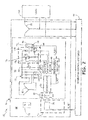
- FIG. 2 is a circuit diagram of a electric power generation and distribution system 60 according to an embodiment of the present invention.
- System 60 includes generator 62, generator control unit (GCU) 64, and load 66.
- Generator 62 includes stationary portion 68 and rotating portion 70.
- Stationary portion 68 includes permanent magnet 72, stationary communication module 74, which includes stationary coil 76, and main armature winding 78.
- Rotating portion 70 includes exciter armature winding 80, rotating communication module 82, which includes rotating coil 84, demodulator 86, PWM current regulator 88, high-side/low-side gate driver 90, rotating rectifier 92, main field rotating power converter 94, main field winding 96, current sensor 98, and internal power supply (IPS) 100.
- IPS internal power supply
- main field rotating power converter is once again implemented with high-side switch T1r, low-side switch T2r and diodes D1r, D2r connected in an asymmetric H-bridge configuration.
- various other circuit configurations may be employed to selectively control the supply of current to main field winding.
- stationary communication module 74 and rotating communication module 82 utilize inductively coupled coils 76 and 84 to transmit information bi-directionally across the airgap.
- other well known means of communicating between a stationary component and a rotating component may be employed.
- rotating portion 70 includes PWM current regulator 88 to provide regulation of the main field winding current.
- PWM current regulator 88 to provide regulation of the main field winding current.
- GCU 64 monitors the output voltage of main armature winding 78. Based on the monitored output voltage, GCU 64 generates a main field winding reference current (labeled I_ref) that is communicated to rotating portion 70 via transformer windings 76 and 84.
- Demodulator 86 demodulates the signal received at secondary winding 84 and provides the received reference current I_ref to PWM current regulator 88, which compares the reference current I_ref to monitored current I_Field. Based on the comparison, PWM current regulator 88 generates command signals provided to high-side/low-side gate driver 90 to selectively turn high-side switch T1r and low-side switch T2r On and Off.
- switch T2r is normally maintained in the On state, while switch T1r is pulse width modulated to generate the desire current through main field winding 96.
- both switches T1r and T2r may be turned Off to provide protection to generator 62 by quickly dissipating the current from main field winding 96.
- the present inventions provide an architecture in which permanent magnets can be used to excite the generator, while still allowing for regulation of the output voltage provided by the generator.
- a generator includes a stationary portion and a rotating portion.
- the stationary portion includes a permanent magnet and a main armature winding.
- the rotating portion includes a main field winding and a main field rotating power converter that regulates current through the main field winding.
- the generator of the preceding paragraph can optionally include, additionally and/or alternatively, any one or more of the following features, configurations and/or additional components:
- the main field rotating power converter may further include a high-side switch connected between a positive DC voltage of a DC bus link and a high side of the main field winding, a low-side switch connected between a negative DC voltage of the DC bus link and a low side of the main field winding, a first diode connected between the high side of the main field winding and the negative DC voltage, and a second diode connected between the low side of the main field winding and the positive DC voltage
- the low-side switch may be turned On and the high-side switch may be modulated On and Off to regulate the current through the main field winding.
- the stationary communication module is located on the stationary portion and the rotating communication module located on the rotating portion may be coupled to receive input from the stationary communication module, wherein the rotating communication module may communicate instructions received from the stationary communication module to the main field rotating power converter to regulate the current through the main field winding.
- the stationary communication module may include a first primary winding and a second primary winding and the rotating communication module includes a first secondary winding and a second secondary winding, wherein the first primary winding is inductively coupled with the first secondary winding to communicate instructions from the stationary portion to the rotating portion and the second primary winding is inductively coupled with the second secondary winding to communicate feedback from the rotating portion to the stationary portion.
- the generator may include a demodulator, a gate drive circuit, a current sensor, a modulator, and a driver circuit.
- the demodulator may be coupled to demodulate instructions communicated via the first primary winding and the first secondary winding.
- the gate drive circuit may control the state of the main field rotating power converter based on the demodulated instructions.
- the current sensor may monitor current through the main field winding.
- the modulator may modulate the sensed current, and the driver circuit may be coupled to the second secondary winding to communicate the modulated sensed current as feedback from the rotating portion to the stationary portion via second secondary winding and the second primary winding.
- the main field rotating power converter may includes a high-side switch connected between a positive DC voltage of a DC link bus and a high side of the main field winding, a low-side switch connected between a negative DC voltage of the DC link bus and a low side of the main field winding, a first diode connected between the high side of the main field winding and the negative DC voltage, and a second diode connected between the low side of the main field winding and the positive DC voltage, wherein current through the main field winding is regulated by maintaining the low-side switch in an On state and pulse width modulating the high-side switch based on demodulated instructions received via the first primary winding and the first secondary winding.
- the stationary communication module may include a primary winding and the rotating communication module may include a secondary winding inductively coupled to the primary winding.
- a demodulator may be coupled to the secondary winding to demodulate instructions received from the primary winding, including a reference current representing a desired current to be provided through the main field winding, and a pulse-width modulator (PWM) current regulator may be connected to monitor current through the main field winding and compare the monitored current to the reference current to calculated PMW control signals provided to the main field rotating power converter to selectively apply the DC voltage to the main field winding.
- PWM pulse-width modulator
- a generator system may include a generator, a stationary communication module, a rotating communication module, a generator control unit, and a main field rotating power converter.
- the generator may include a stationary portion and a rotating portion, wherein the generator includes permanent magnets located on the stationary portion to provide excitation to the rotating portion, and a main field winding on the rotating portion that induces a generator output voltage on a main armature winding located on the stationary portion.
- the rotating communication module located on the rotating portion of the generator may be configured to receive communications from the stationary communication module.
- the generator control unit may be connected to monitor the output voltage generated by the main armature winding of the generator and to provide instructions via the stationary communication module to the rotating portion of the generator.
- the main field rotating power converter located on the rotating portion of the generator that may, in response to instructions received from the GCU, regulate current through the main field winding to regulate the output voltage of the generator.
- the generator system of the preceding paragraph can optionally include, additionally and/or alternatively, any one or more of the following features, configurations and/or additional components:
- the generator control unit in response to monitored output voltage of the generator, may provide instructions to the rotating portion of the generator to selectively turn main field rotating power converter On and Off to regulate current through the main field winding.
- the generator control unit in response to monitored output voltage of the generator, may provide a current reference value to the rotating portion of the generator, wherein the rotating portion includes a pulse-width modulation current regulator that selectively turns the main field rotating power converter On and Off to regulate the current through the main field winding.
- the main field rotating power converter may includes a high-side switch connected between a positive DC voltage of a DC bus link and a high side of the main field winding, a low-side switch connected between a negative DC voltage of the DC bus link and a low side of the main field winding, a first diode connected between the high side of the main field winding and the negative DC voltage, and a second diode connected between the low side of the main field winding and the positive DC voltage.
- the low-side switch may be turned On and the high-side switch may be modulated On and Off to regulate the current through the main field winding.
- the generator system may further include an exciter armature winding located on the rotating portion that provides an alternating current (AC) voltage in response to the permanent magnets and a rotating rectifier that rectifies the AC voltage provided by the exciter armature winding to a direct current (DC) voltage provided to the main field rotating power converter via a DC link bus, wherein the main field rotating power converter selectively applies voltage from the DC link bus to the main field winding to develop current through the main field winding.
- AC alternating current
- DC direct current
- the stationary communication module may include a primary winding and the rotating communication module may include a secondary winding inductively coupled with the primary winding to allow the generator control unit to provide control instructions to the rotating portion.
- the stationary communication module may include a first primary winding and a second primary winding and the rotating communication module may include a first secondary winding inductively coupled with the first primary winding and a second secondary winding inductively coupled with the second primary winding, wherein the generator control unit sends control instructions to the rotating portion via the first primary winding and receives feedback from the rotating portion via the second primary winding.
Landscapes
- Engineering & Computer Science (AREA)
- Power Engineering (AREA)
- Control Of Eletrric Generators (AREA)
- Synchronous Machinery (AREA)
- Permanent Magnet Type Synchronous Machine (AREA)
Applications Claiming Priority (1)
| Application Number | Priority Date | Filing Date | Title |
|---|---|---|---|
| US13/833,212 US9325229B2 (en) | 2013-03-15 | 2013-03-15 | Generator architecture with PMG exciter and main field rotating power converter |
Publications (2)
| Publication Number | Publication Date |
|---|---|
| EP2779426A2 true EP2779426A2 (de) | 2014-09-17 |
| EP2779426A3 EP2779426A3 (de) | 2016-03-23 |
Family
ID=50239551
Family Applications (1)
| Application Number | Title | Priority Date | Filing Date |
|---|---|---|---|
| EP14159210.5A Withdrawn EP2779426A3 (de) | 2013-03-15 | 2014-03-12 | Generatorarchitektur mit PMG-Erreger und rotierendem Hauptfeld-Leistungswandler |
Country Status (2)
| Country | Link |
|---|---|
| US (1) | US9325229B2 (de) |
| EP (1) | EP2779426A3 (de) |
Cited By (3)
| Publication number | Priority date | Publication date | Assignee | Title |
|---|---|---|---|---|
| EP3046235A1 (de) * | 2015-01-16 | 2016-07-20 | Hamilton Sundstrand Corporation | Synchrone maschine mit wiederaufladbaren energiespeichervorrichtungen |
| EP3109997A3 (de) * | 2015-06-24 | 2017-01-04 | Hamilton Sundstrand Corporation | Permanentmagneterreger stromgenerator konstanter frequenz betrieben mit variabler geschwindigkeit |
| ITUA20163299A1 (it) * | 2016-05-10 | 2017-11-10 | Idm Srl | Alternatore multipolare perfezionato |
Families Citing this family (17)
| Publication number | Priority date | Publication date | Assignee | Title |
|---|---|---|---|---|
| US9525376B2 (en) * | 2014-05-13 | 2016-12-20 | Gbox, Llc | Wound field synchronous machine with resonant field exciter |
| US9771164B2 (en) | 2014-10-27 | 2017-09-26 | Hamilton Sundstrand Corporation | Electric system architecture included in a more-electric engine (MEE) system |
| US10256758B2 (en) | 2014-11-26 | 2019-04-09 | Kohler Co. | Printed circuit board based exciter |
| US20160268942A1 (en) * | 2015-03-12 | 2016-09-15 | Hamilton Sundstrand Corporation | Control of Hybrid Permanent Magnet Machine With Rotating Power Converter and Energy Source |
| US9660563B2 (en) | 2015-06-19 | 2017-05-23 | Hamilton Sundstrand Corporation | High voltage direct current system with improved generator excitation |
| US9941827B2 (en) * | 2016-06-08 | 2018-04-10 | Hamilton Sundstrand Corporation | High voltage DC power generating system including selectively removable neutral node |
| US10486537B2 (en) | 2016-08-29 | 2019-11-26 | Hamilton Sundstrand Corporation | Power generating systems having synchronous generator multiplex windings and multilevel inverters |
| US11043880B2 (en) | 2016-11-10 | 2021-06-22 | Hamilton Sunstrand Corporation | Electric power generating system with a synchronous generator |
| US10498274B2 (en) | 2016-11-10 | 2019-12-03 | Hamilton Sundstrand Corporation | High voltage direct current system for a vehicle |
| DE102017201687A1 (de) * | 2017-02-02 | 2018-08-02 | Siemens Aktiengesellschaft | Regelbare Spannungserzeugungsvorrichtung und Verfahren zum Betreiben einer regelbaren Spannungserzeugungsvorrichtung |
| US10128785B1 (en) | 2017-05-22 | 2018-11-13 | General Electric Company | Systems and methods for mitigating transient events in a power generation system |
| US10425026B2 (en) * | 2017-11-21 | 2019-09-24 | The Boeing Company | Independent speed variable frequency alternating current generator |
| US10454278B2 (en) | 2018-01-09 | 2019-10-22 | The Boeing Company | Independent speed variable frequency based electrified propulsion system architecture |
| US10581357B2 (en) * | 2018-05-11 | 2020-03-03 | Abb Schweiz Ag | Rotating direct current power supply for synchronous machines |
| GB2578433B (en) * | 2018-10-25 | 2022-08-17 | Safran Electrical & Power | Electric machine control |
| US11362567B2 (en) * | 2020-01-16 | 2022-06-14 | The Boeing Company | Electrical power generation from turbine engines |
| US11193426B2 (en) | 2020-04-16 | 2021-12-07 | The Boeing Company | Electrically geared turbofan |
Family Cites Families (45)
| Publication number | Priority date | Publication date | Assignee | Title |
|---|---|---|---|---|
| US3671850A (en) | 1970-11-19 | 1972-06-20 | Walter E Mehnert | Electric generator control system with radio feedback loop |
| US3768002A (en) | 1971-10-01 | 1973-10-23 | Gen Electric | Generator excitation system with rotating electromagnetic energy connector and internal winding power source |
| US3908161A (en) * | 1974-02-07 | 1975-09-23 | Gen Electric | Field excitation system for synchronous machines utilizing a rotating transformer brushless exciter generating combination |
| DE2945599C2 (de) | 1979-11-12 | 1985-07-11 | Siemens AG, 1000 Berlin und 8000 München | Einrichtung zur Pendelungsdämpfung von geregelten elektrischen Maschinen |
| DE3126318A1 (de) * | 1981-06-26 | 1983-01-13 | Siemens AG, 1000 Berlin und 8000 München | Elektrischer stromrichtermotor synchroner bauart |
| DE3206338A1 (de) | 1982-02-22 | 1983-09-01 | Kraftwerk Union AG, 4330 Mülheim | Anordnung fuer die kontakt- und beruehrungslose uebertragung von mess- und steuersignalen |
| US4694654A (en) * | 1983-10-29 | 1987-09-22 | Isuzu Motors Limited | Exhaust energy recovery and generator for use with an engine |
| US4625160A (en) | 1984-12-17 | 1986-11-25 | Sundstrand Corporation | Variable speed constant frequency generating system |
| US4723106A (en) | 1986-08-29 | 1988-02-02 | General Electric Company | Brushless generator exciter using hybrid rectifier |
| US5029263A (en) | 1989-10-19 | 1991-07-02 | Sundstrand Corporation | Electric start control of a VSCF system |
| US5153498A (en) | 1989-11-07 | 1992-10-06 | Sundstrand Corporation | Generic control unit |
| US5097195A (en) * | 1989-11-27 | 1992-03-17 | Sundstrand Corporation | AC exciter for VSCF starter/generator |
| US5068590A (en) * | 1989-12-20 | 1991-11-26 | Sundstrand Corporation | Brushless generator having AC excitation in generating and starting modes |
| US5055765A (en) | 1990-09-04 | 1991-10-08 | Sundstrand Corporation | Voltage regulator for direct current aircraft power bus |
| US5233286A (en) | 1991-07-29 | 1993-08-03 | Sundstrand Corporation | Hybrid 270 volt DC system |
| US5309081A (en) * | 1992-08-18 | 1994-05-03 | Sundstrand Corporation | Power conversion system with dual permanent magnet generator having prime mover start capability |
| US5594322A (en) * | 1993-05-12 | 1997-01-14 | Sundstrand Corporation | Starter/generator system with variable-frequency exciter control |
| US5488286A (en) | 1993-05-12 | 1996-01-30 | Sundstrand Corporation | Method and apparatus for starting a synchronous machine |
| US5430362A (en) * | 1993-05-12 | 1995-07-04 | Sundstrand Corporation | Engine starting system utilizing multiple controlled acceleration rates |
| US5493200A (en) * | 1993-05-12 | 1996-02-20 | Sundstrand Corporation | Control for a brushless generator |
| US6095268A (en) * | 1998-01-28 | 2000-08-01 | Mattel, Inc. | Children's ride-on vehicle with independently driven and reversible wheels |
| SE514068C2 (sv) | 1999-04-30 | 2000-12-18 | Abb Ab | Roterande kraftsystemsstabilisator |
| SE514818C2 (sv) | 1999-04-30 | 2001-04-30 | Abb Ab | Konstantfrekvensmaskin med varierande/varierbart varvtal samt förfarande vid dylik maskin |
| JP2001112215A (ja) * | 1999-10-05 | 2001-04-20 | Yaskawa Electric Corp | 減速機一体型アクチュエータ |
| US6420842B1 (en) | 2000-01-11 | 2002-07-16 | American Superconductor Corporation | Exciter and electronic regulator for rotating machinery |
| JP4045730B2 (ja) * | 2000-09-14 | 2008-02-13 | 株式会社デンソー | 車両用交流発電機 |
| US6998726B2 (en) * | 2002-12-10 | 2006-02-14 | Honeywell International Inc. | Method and system for providing single-phase excitation techniques to a start exciter in a starter/generator system |
| US7009365B1 (en) | 2004-08-31 | 2006-03-07 | General Motors Corporation | Systems and methods for control of vehicle electrical generator |
| US7064524B2 (en) | 2004-09-08 | 2006-06-20 | Honeywell International Inc. | Method and apparatus for generator control |
| US7196498B2 (en) | 2004-09-08 | 2007-03-27 | Honeywell International Inc. | Method and apparatus for generator control |
| GB2455122A (en) * | 2007-11-29 | 2009-06-03 | Technelec Ltd | Control of electrical machines |
| GB2455123A (en) * | 2007-11-29 | 2009-06-03 | Technelec Ltd | Control of electrical machines |
| WO2009116572A1 (ja) * | 2008-03-19 | 2009-09-24 | 三洋電機株式会社 | 永久磁石同期モータ |
| US20110018272A1 (en) * | 2008-11-18 | 2011-01-27 | Lehoczky Kalman N | Direct driven free flow turbine |
| US7920427B2 (en) | 2009-02-13 | 2011-04-05 | Micron Technology, Inc. | Dynamic soft program trims |
| US8730702B2 (en) | 2009-03-03 | 2014-05-20 | Renewable Power Conversion, Inc. | Very high efficiency three phase power converter |
| GB2469128A (en) | 2009-04-04 | 2010-10-06 | Dyson Technology Ltd | Generating control signals for an electric machine from a position sensor |
| US8299762B2 (en) * | 2009-06-05 | 2012-10-30 | Hamilton Sundstrand Corporation | Starting/generating system with multi-functional circuit breaker |
| EP2615721B1 (de) * | 2010-09-06 | 2018-05-30 | Mitsubishi Electric Corporation | Elektrische permanentmagnetrotationsmaschine und elektrische servolenkvorrichtung damit |
| US8773080B2 (en) | 2010-12-16 | 2014-07-08 | Kohler Co. | Resonant commutation system for exciting a three-phase alternator |
| US8810189B2 (en) | 2011-02-25 | 2014-08-19 | Deere & Company | Machine systems including pre-power diagnostics |
| JP5936700B2 (ja) * | 2012-10-01 | 2016-06-22 | 三菱電機株式会社 | 電動駆動装置 |
| JP6305394B2 (ja) * | 2013-04-09 | 2018-04-04 | 三菱電機株式会社 | 永久磁石型モータ及び電動パワーステアリング装置 |
| US9985507B2 (en) * | 2013-04-22 | 2018-05-29 | Mitsubishi Electric Corporation | Permanent magnet type motor |
| US9209741B2 (en) * | 2014-02-24 | 2015-12-08 | The Boeing Company | Method and system for controlling synchronous machine as generator/starter |
-
2013
- 2013-03-15 US US13/833,212 patent/US9325229B2/en active Active
-
2014
- 2014-03-12 EP EP14159210.5A patent/EP2779426A3/de not_active Withdrawn
Non-Patent Citations (1)
| Title |
|---|
| None |
Cited By (4)
| Publication number | Priority date | Publication date | Assignee | Title |
|---|---|---|---|---|
| EP3046235A1 (de) * | 2015-01-16 | 2016-07-20 | Hamilton Sundstrand Corporation | Synchrone maschine mit wiederaufladbaren energiespeichervorrichtungen |
| US9998047B2 (en) | 2015-01-16 | 2018-06-12 | Hamilton Sundstrand Corporation | Synchronous machine with rechargeable power storage devices |
| EP3109997A3 (de) * | 2015-06-24 | 2017-01-04 | Hamilton Sundstrand Corporation | Permanentmagneterreger stromgenerator konstanter frequenz betrieben mit variabler geschwindigkeit |
| ITUA20163299A1 (it) * | 2016-05-10 | 2017-11-10 | Idm Srl | Alternatore multipolare perfezionato |
Also Published As
| Publication number | Publication date |
|---|---|
| US9325229B2 (en) | 2016-04-26 |
| US20140265744A1 (en) | 2014-09-18 |
| EP2779426A3 (de) | 2016-03-23 |
Similar Documents
| Publication | Publication Date | Title |
|---|---|---|
| US9325229B2 (en) | Generator architecture with PMG exciter and main field rotating power converter | |
| US9054610B2 (en) | Generator architecture with main field rotating power converter | |
| EP2779420B1 (de) | Verfahren zur Regelung der Drehung eines Hauptfeldumsetzers | |
| EP2779424B1 (de) | EPGS-Architektur mit mehrkanaligem Synchrongenerator und gemeinsamem unreguliertem PMG-Erreger | |
| EP2779425B1 (de) | Egps-architektur mit mehrkanaligem synchrongenerator und reguliertem erreger mit gemeinsamem feld | |
| US8427116B2 (en) | Starting/generating system with multi-functional circuit breaker | |
| US8970183B2 (en) | Overvoltage limiter in an aircraft electrical power generation system | |
| EP2779428B1 (de) | System mit veränderlicher geschwindigkeit und konstanter frequenz mit generator und rotierendem leistungswandler | |
| US9318937B2 (en) | Flux controlled PM electric machine rotor | |
| US9729036B2 (en) | Permanent magnet machine for integrated starter generator | |
| US9088230B2 (en) | Dual generator system | |
| JP2012228033A (ja) | 車両用発電機 | |
| EP2775592A2 (de) | Generator für ein Energieerzeugungssystem | |
| JP6466575B2 (ja) | 同期機への励磁電流の供給 | |
| EP3255779B1 (de) | Rekonfigurierbares, auf multi-permanentmagnetgenerator basierendes energieerzeugungssystem | |
| US11462982B2 (en) | Hybrid permanent magnet and wound rotor starter generator | |
| US10044305B2 (en) | Controlling aircraft VFG over voltage under fault or load-shed |
Legal Events
| Date | Code | Title | Description |
|---|---|---|---|
| 17P | Request for examination filed |
Effective date: 20140312 |
|
| AK | Designated contracting states |
Kind code of ref document: A2 Designated state(s): AL AT BE BG CH CY CZ DE DK EE ES FI FR GB GR HR HU IE IS IT LI LT LU LV MC MK MT NL NO PL PT RO RS SE SI SK SM TR |
|
| AX | Request for extension of the european patent |
Extension state: BA ME |
|
| PUAI | Public reference made under article 153(3) epc to a published international application that has entered the european phase |
Free format text: ORIGINAL CODE: 0009012 |
|
| PUAL | Search report despatched |
Free format text: ORIGINAL CODE: 0009013 |
|
| AK | Designated contracting states |
Kind code of ref document: A3 Designated state(s): AL AT BE BG CH CY CZ DE DK EE ES FI FR GB GR HR HU IE IS IT LI LT LU LV MC MK MT NL NO PL PT RO RS SE SI SK SM TR |
|
| AX | Request for extension of the european patent |
Extension state: BA ME |
|
| RIC1 | Information provided on ipc code assigned before grant |
Ipc: H02K 19/36 20060101ALI20160212BHEP Ipc: H02P 9/30 20060101ALI20160212BHEP Ipc: H02P 9/48 20060101AFI20160212BHEP |
|
| STAA | Information on the status of an ep patent application or granted ep patent |
Free format text: STATUS: THE APPLICATION IS DEEMED TO BE WITHDRAWN |
|
| 18D | Application deemed to be withdrawn |
Effective date: 20160924 |