EP2779421B1 - Integrierter Startergenerator - Google Patents
Integrierter Startergenerator Download PDFInfo
- Publication number
- EP2779421B1 EP2779421B1 EP14159408.5A EP14159408A EP2779421B1 EP 2779421 B1 EP2779421 B1 EP 2779421B1 EP 14159408 A EP14159408 A EP 14159408A EP 2779421 B1 EP2779421 B1 EP 2779421B1
- Authority
- EP
- European Patent Office
- Prior art keywords
- flux
- control coil
- rotating
- regulated
- pmm
- Prior art date
- Legal status (The legal status is an assumption and is not a legal conclusion. Google has not performed a legal analysis and makes no representation as to the accuracy of the status listed.)
- Active
Links
- 239000007858 starting material Substances 0.000 title description 2
- 230000004907 flux Effects 0.000 claims description 79
- 238000004804 winding Methods 0.000 claims description 72
- 230000005291 magnetic effect Effects 0.000 claims description 57
- 230000001105 regulatory effect Effects 0.000 claims description 33
- 230000005294 ferromagnetic effect Effects 0.000 claims description 15
- 230000003247 decreasing effect Effects 0.000 claims description 13
- 230000001360 synchronised effect Effects 0.000 claims description 9
- 230000005284 excitation Effects 0.000 claims description 8
- 230000001276 controlling effect Effects 0.000 claims description 4
- 230000007423 decrease Effects 0.000 description 8
- 230000008901 benefit Effects 0.000 description 3
- 230000001419 dependent effect Effects 0.000 description 2
- 238000010586 diagram Methods 0.000 description 2
- 230000035699 permeability Effects 0.000 description 2
- 230000009286 beneficial effect Effects 0.000 description 1
- 230000008878 coupling Effects 0.000 description 1
- 238000010168 coupling process Methods 0.000 description 1
- 238000005859 coupling reaction Methods 0.000 description 1
- 230000003993 interaction Effects 0.000 description 1
Images


Classifications
-
- H—ELECTRICITY
- H02—GENERATION; CONVERSION OR DISTRIBUTION OF ELECTRIC POWER
- H02K—DYNAMO-ELECTRIC MACHINES
- H02K21/00—Synchronous motors having permanent magnets; Synchronous generators having permanent magnets
- H02K21/02—Details
- H02K21/04—Windings on magnets for additional excitation ; Windings and magnets for additional excitation
-
- H—ELECTRICITY
- H02—GENERATION; CONVERSION OR DISTRIBUTION OF ELECTRIC POWER
- H02P—CONTROL OR REGULATION OF ELECTRIC MOTORS, ELECTRIC GENERATORS OR DYNAMO-ELECTRIC CONVERTERS; CONTROLLING TRANSFORMERS, REACTORS OR CHOKE COILS
- H02P9/00—Arrangements for controlling electric generators for the purpose of obtaining a desired output
-
- H—ELECTRICITY
- H02—GENERATION; CONVERSION OR DISTRIBUTION OF ELECTRIC POWER
- H02K—DYNAMO-ELECTRIC MACHINES
- H02K19/00—Synchronous motors or generators
- H02K19/16—Synchronous generators
- H02K19/38—Structural association of synchronous generators with exciting machines
-
- H—ELECTRICITY
- H02—GENERATION; CONVERSION OR DISTRIBUTION OF ELECTRIC POWER
- H02P—CONTROL OR REGULATION OF ELECTRIC MOTORS, ELECTRIC GENERATORS OR DYNAMO-ELECTRIC CONVERTERS; CONTROLLING TRANSFORMERS, REACTORS OR CHOKE COILS
- H02P9/00—Arrangements for controlling electric generators for the purpose of obtaining a desired output
- H02P9/14—Arrangements for controlling electric generators for the purpose of obtaining a desired output by variation of field
- H02P9/26—Arrangements for controlling electric generators for the purpose of obtaining a desired output by variation of field using discharge tubes or semiconductor devices
- H02P9/30—Arrangements for controlling electric generators for the purpose of obtaining a desired output by variation of field using discharge tubes or semiconductor devices using semiconductor devices
- H02P9/302—Brushless excitation
-
- H—ELECTRICITY
- H02—GENERATION; CONVERSION OR DISTRIBUTION OF ELECTRIC POWER
- H02P—CONTROL OR REGULATION OF ELECTRIC MOTORS, ELECTRIC GENERATORS OR DYNAMO-ELECTRIC CONVERTERS; CONTROLLING TRANSFORMERS, REACTORS OR CHOKE COILS
- H02P9/00—Arrangements for controlling electric generators for the purpose of obtaining a desired output
- H02P9/14—Arrangements for controlling electric generators for the purpose of obtaining a desired output by variation of field
- H02P9/34—Arrangements for controlling electric generators for the purpose of obtaining a desired output by variation of field using magnetic devices with controllable degree of saturation in combination with controlled discharge tube or controlled semiconductor device
-
- H—ELECTRICITY
- H02—GENERATION; CONVERSION OR DISTRIBUTION OF ELECTRIC POWER
- H02P—CONTROL OR REGULATION OF ELECTRIC MOTORS, ELECTRIC GENERATORS OR DYNAMO-ELECTRIC CONVERTERS; CONTROLLING TRANSFORMERS, REACTORS OR CHOKE COILS
- H02P2101/00—Special adaptation of control arrangements for generators
- H02P2101/30—Special adaptation of control arrangements for generators for aircraft
Definitions
- the present invention is related to starter-generators, and in particular to a starter-generator that utilizes a permanent magnet exciter.
- a generator converts mechanical energy to electrical energy.
- a motor converts electrical energy to mechanical energy. From a mechanical standpoint, the main difference between a generator and a motor is the direction in which energy flows.
- Applications that require motoring operations and generating operations, an integrated motor-generator can meet both requirements via a single device.
- the motor-generator is used in a motoring mode to convert electrical energy to mechanical energy, and in a generating mode to convert mechanical energy to electrical energy.
- a motor referred to as a starter is required to provide mechanical force to the engines for starting.
- the motor-generator is commonly referred to as a starter-generator.
- a typical integrated starter-generator includes a main wound-field synchronous machine, an exciter, and a sub-exciter.
- the sub-exciter During operation in the generating mode, the sub-exciter generates electric power that is provided as excitation to the exciter.
- the sub-exciter is a permanent magnet generator utilizing a permanent magnet rotor and three-phase stator.
- the permanent magnet rotor When rotating, the permanent magnet rotor induces an alternating current voltage on the three-phase stator that is rectified and provided as a direct current (DC) voltage to the exciter, causing current to build up in the stationary exciter field winding.
- DC direct current
- the current through the exciter field winding induces an AC voltage on the rotating exciter armature windings.
- the AC voltage is rectified and provided as a DC voltage to a rotating main field winding, which causes current to build through the main field winding.
- the current through the main field winding induces an AC voltage on the main armature windings of the ISG.
- the voltage provided on the main armature windings of the ISG is regulated by controlling the current supplied to the exciter field winding. Increasing the current through the exciter field winding increases the generator output voltage, while decreasing the current through the exciter field winding decreases the generator output voltage.
- ISG integrated starter-generator
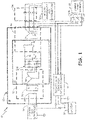
- FIG. 1 is a circuit diagram of wound-field integrated starter-generator (ISG) system 10 having a flux-regulated permanent magnet machine (PMM) according to an embodiment of the present invention.
- System 10 includes integrated starter-generator (ISG) 12, control coil controller 14, battery 16, isolated AC-DC converter/battery charger 18, main output contactors 20a and 20b, AC load management and distribution system 22, and engine start inverter 24.
- ISG 12 includes stationary portion 28 and rotating portion 30, and two separate electromechanical machines: flux-regulated PMM 32 and wound field synchronous machine 35.
- Flux-regulated PMM 32 includes control coil 33 and permanent magnets 34 located on stationary portion 28 and exciter armature windings 38 located on rotating portion 30.
- Wound field synchronous machine 35 includes main armature winding 36 located on stationary portion 28 and main field winding 42 located on rotating portion 30.
- flux-regulated PMM 32 is connected to provide excitation to wound-field synchronous machine 35 via rotating rectifier 40 and DC link bus 41 located on rotating portion 30..
- a generate mode magnetic flux provided by permanent magnets 34 interacts with rotating PMG windings 38 to induce an AC voltage on PMG windings 38.
- Rotating rectifier 38 rectifies the AC voltage and provides the rectified voltage to main field winding 42 via DC link bus 41.
- the DC voltage applied to main field winding 42 causes current to build in main field winding 42, which induces an AC voltage in main armature winding 36.
- the AC output voltage of ISG 12 is provided to AC load management and distribution system 22 via main output contactors 20a.
- the generator output voltage is regulated by regulating the current through an exciter field winding.
- the exciter field winding has been replaced with control coil 33 and permanent magnets 34.
- the magnetic flux provided by permanent magnets 34 is varied based on the current supplied to control coil 33. In this way, the voltage induced on exciter armature windings 38 can be regulated. As a result, the voltage supplied to main field winding 42 and resulting voltage induced on main armature winding 36 can be regulated via the current supplied to control coil 33 by control coil controller 14.
- isolated AC-DC converter 18 is connected to convert the AC output voltage of ISG 12 to a DC voltage that is supplied to battery 16 and control coil controller 14.
- the DC voltage supplied to battery 16 provides charging current to the battery, which is used if AC voltage is unavailable to provide power to control coil controller 14.
- the DC voltage supplied to control coil controller 14 is selectively applied to control 33 to increase or decrease the output voltage of ISG 12 as desired.
- engine start inverter 24 provides an AC voltage to main armature winding 36 via main output contactors 20b to generate a rotating magnetic field.
- Excitation provided to main field winding 42 generates a stationary magnetic field (at least initially) that interacts with the rotating magnetic field to cause rotating portion 40 to rotate relative to stationary portion 28.
- the excitation for main field winding 42 is provided by hybrid field excitation module 32.
- the magnetic flux provided by permanent magnets 34 does not rotate, so an AC voltage is supplied to control coil 33 in order to induce a rotating magnetic field that will induce an AC voltage on PMG windings 38 while rotating portion 30 is stationary (during initial start-up conditions).
- Rotating rectifier 38 once again rectifies the AC voltage and provides the rectified voltage to main field winding 42 via DC link bus 41 to generate a magnetic field to interact with the rotating magnetic field provided by main armature winding 36.
- flux-regulated PMM 32 takes advantage of the benefits associated with permanent magnets as well as the control offered by control winding 33.
- control coil controller 14 selectively applies current to control coil 33 to either increase or decrease the magnetic flux presented to PMG windings 38, thereby allowing the output voltage of IDG 12 to be regulated.
- a benefit of this approach is instead of three separate machines (e.g., a PMG, an exciter, and a main wound-field synchronous machine), only two machines (e.g., flux-regulated PMM 32 and main wound-field synchronous machine) are required.
- FIG. 2 is a cross-sectional view of an example flux-regulated PMM 32'.
- the stationary portion of flux-regulated PMM 32' includes a plurality of poles 50 extending from ferromagnetic yoke 52, a plurality of permanent magnets 34', and control coil 33'.
- rotating armature windings 38 representing the rotating portion of flux-regulated PMM 32', are positioned radially interior the stationary components and are supported by shaft 60. Rotating armature windings 38 are therefore positioned to interact with the magnetic flux provided across the airgap separating rotating and stationary components.
- Each of the plurality of poles 50 extends radially inward from ferromagnetic yoke 52, with a permanent magnet 34' positioned on each of the plurality of poles 50.
- Adjacent permanent magnets 34' are of opposite magnetic polarity, such that magnetic flux is directed from each permanent magnet to its corresponding neighbors via a magnetic circuit path.
- the amount of magnetic flux depends, in part, on the reluctance associated with the magnetic circuit path. By increasing the reluctance of the circuit path, the magnetic flux presented to rotating armature windings 38 is decreased, and vice versa.
- control coil 33' is wound around each of the plurality of poles 50 and is utilized to selectively vary the magnetic reluctance of the plurality of poles 50.
- the magnetic flux of coils 33' and flux of permanent magnets 34' are in direct opposition.
- Application of a control current through control coil 33' increases the reluctance of the plurality of poles 50, and therefore decreases the magnetic flux presented to rotating armature windings 38.
- the magnetic flux presented to rotating armature windings 38 can be increased by decreasing the control current through control coil 33'.
- the magnetic flux supplied to rotating armature windings 38 is therefore maximized in the embodiment shown in FIG.
- l Fe is the length of a portion of the magnetic circuit
- S Fe is the cross section of a portion of the magnetic circuit
- ⁇ 0 0.4 ⁇ ⁇ 10 -6 H / m
- ⁇ r (V c ) is the relative magnetic permeability dependent on the control voltage V c .
- the relative magnetic permeability ⁇ r is a nonlinear function of the control voltage Vc.
- V ⁇ is the magnetic potential drop across the length l Fe of the magnetic circuit.
- Equations 1 and 2 illustrate that the reluctance of poles 50 is a function of the current through control coil 33', and that the magnetic flux is inversely proportional to the reluctance, such that an increase in current through control coil 33' decreases the magnetic flux presented to armature windings 38. In FIG. 2 , flux (and therefore output voltage of the generator) is maximized when no current is applied to control coil 33'.
- FIG. 3 is a cross-sectional view of flux-regulated PMM 32" according to an embodiment of the present invention.
- the stationary portion of flux-regulated PMM 32" includes ferromagnetic yoke 52, a plurality of permanent magnets 34", a plurality of flux diverters (shunts) 62, and control coil 33" wound around flux diverters 62.
- the plurality of permanent magnets 34" are uniformly distributed around the interior periphery of field excitation module 32", with ferromagnetic yoke 52 magnetically coupling each of the plurality of permanent magnets 34" to one another to form a magnetic circuit path.
- Rotating armature winding 38 is once again positioned radially interior of permanent magnets 34", and is supported by shaft 60 for rotation.
- Flux diverters 62 are connected between adjacent permanent magnets 34", providing a low reluctance path for magnetic flux to travel between adjacent poles. Magnetic flux flowing between adjacent permanent magnets 34" is a "leakage” flux that decreases the magnetic flux presented to rotating armature windings 38.
- the reluctance of flux diverters 62 is dependent, once again, on the control current supplied to control coil 33". By increasing the current through control coil 33", the reluctance of flux diverters 62 is increased.
- the magnetic flux through each diverter 62 is decreased, and correspondingly the magnetic flux provided to armature windings 38 is increased.
- the magnetic flux provided to armature winding 38 is maximized when the control current is zero
- the magnetic flux provided to armature winding 38 is maximized when the control current is large (i.e., non-zero) and minimized when the control current is zero.
- the embodiment described with respect to FIG. 3 is beneficial because it requires a control current in order to maximize the generator output voltage, and therefore maintains the output of the generator at a "safe" level in the event no control current is available (e.g., fault condition).
- An integrated starter-generator (ISG) system includes a flux-regulated permanent magnet machine (PMM), a wound-field synchronous machine, and a control coil controller.
- the flux-regulated PMM may include a stationary portion that includes a control coil and a plurality of permanent magnets, and a rotating portion that includes rotating armature windings.
- the wound-field synchronous machine may include a stationary portion that includes a main armature winding and a rotating portion that includes a main field winding that receives excitation from the flux-regulated PMM.
- the control coil controller controls current supplied to the control coil of the flux-regulated PMM to selectively control magnetic flux presented to the rotating armature windings.
- the ISG of the preceding paragraph can optionally include, additionally and/or alternatively, any one or more of the following features, configurations and/or additional components.
- the stationary portion may be positioned radially exterior to the rotating portion and may further include a ferromagnetic yoke and a plurality of poles extending radially inward from the ferromagnetic yoke toward the rotating portion, wherein each of the plurality of poles includes one of the plurality of permanent magnets, and the control coil is wrapped around each of the plurality of poles.
- control coil controller may increase the magnetic flux presented to the rotating armature windings by decreasing the current through the control coil.
- control coil controller may decrease the magnetic flux presented to the rotating armature windings by increasing the current through the control coil.
- control coil controller may regulate an output voltage generated by the main armature winding by selectively controlling the current through the control coil.
- the stationary portion may be positioned radially exterior to the rotating portion and may further include a ferromagnetic yoke, wherein the plurality of permanent magnets extend radially inward from the ferromagnetic yoke towards the rotating portion, and a plurality of flux diverters connected between each of the plurality of adjacent permanent magnets, wherein the control coil is wound around each of the flux diverters.
- control coil controller may increase the magnetic flux presented to the rotating armature windings by increasing the current through the control coil.
- control coil controller may decrease the magnetic flux presented to the rotating armature windings by decreasing the current through the control coil.
- control coil controller may regulate an output voltage generated by the main armature winding by selectively controlling the current through the control coil.
- a flux-regulated permanent magnet machine may include a rotating portion and a stationary portion.
- the rotating portion may include a rotating armature winding.
- the stationary portion may be positioned radially exterior to the rotating portion and may include a ferromagnetic yoke, a plurality of poles extending radially inward from the ferromagnetic yoke towards the rotating portion, a plurality of permanent magnets, each permanent magnet located on one of the plurality of poles, and a control coil wound around each of the plurality of poles.
- the magnetic flux presented to the rotating armature windings may be increased by decreasing the current through the control coil.
- the magnetic flux presented to the rotating armature windings may be decreased by increasing the current through the control coil.
- a flux-regulated permanent magnet machine may include a rotating portion and a stationary portion.
- the rotating portion may further include a rotating armature winding.
- the stationary portion may be positioned radially exterior to the rotating portion, and may further include a ferromagnetic yoke, a plurality of permanent magnets extending radially inward from the ferromagnetic yoke towards the rotating portion, a flux diverter connected between each of the plurality of adjacent permanent magnets, and a control coil wound around each of the flux diverters.
- the magnetic flux presented to the rotating armature windings may be increased by increasing the current through the control coil.
- the magnetic flux presented to the rotating armature windings may be decreased by decreasing the current through the control coil.
Landscapes
- Engineering & Computer Science (AREA)
- Power Engineering (AREA)
- Control Of Eletrric Generators (AREA)
- Permanent Magnet Type Synchronous Machine (AREA)
Claims (6)
- Flussregulierte Permanentmagnetmaschine (PMM), umfassend:eine Steuerspule (33, 33', 33"), die dazu konfiguriert ist, von einer Steuerspulensteuerung Gleichstrom während eines Erzeugungsmodus und Wechselstrom während eines Motormodus aufzunehmen;einen rotierenden Abschnitt (30), der eine rotierende Ankerwicklung (38, 38', 38") beinhaltet; undeinen feststehenden Abschnitt (28), der radial auswärts des rotierenden Abschnitts (30) positioniert ist, wobei der feststehende Abschnitt (28) Folgendes beinhaltet:ein ferromagnetisches Joch (52) undeine Vielzahl von Permanentmagneten (34, 34', 34"), die sich von dem ferromagnetischen Joch radial einwärts zum rotierenden Abschnitt (30) erstreckt; und gekennzeichnet durcheine Vielzahl von Flussumlenkern (62), die zwischen jedem von der Vielzahl von angrenzenden Permanentmagneten verbunden ist; undwobei die Steuerspule (33, 33', 33") um jeden der Flussumlenker (62) gewickelt ist.
- Flussregulierte PMM nach Anspruch 1, ferner umfassend:
eine Vielzahl von Polen (50), die sich von dem ferromagnetischen Joch (60) radial einwärts zu dem rotierenden Abschnitt (30) erstreckt; wobei jeder aus der Vielzahl von Polen (50) einen von der Vielzahl von Permanentmagneten beinhaltet. - Flussregulierte PMM nach Anspruch 2, wobei der Magnetfluss, der an den rotierenden Ankerwicklungen zur Verfügung gestellt wird, durch Erhöhen des Stroms durch die Steuerspule erhöht wird.
- Flussregulierte PMM nach Anspruch 2, wobei der Magnetfluss, der an den rotierenden Ankerwicklungen zur Verfügung gestellt wird, durch Verringern des Stroms durch die Steuerspule verringert wird.
- Integriertes Startergenerator(ISG)-System (10), umfassend:die flussregulierte Permanentmagnetmaschine (PMM) nach einem der Ansprüche 1 bis 4;eine elektrisch erregte Synchronmaschine (35), die den feststehenden Abschnitt (28, 28', 28"), der eine Hauptankerwicklung (36) beinhaltet, und den rotierenden Abschnitt (30) beinhaltet, der eine Hauptfeldwicklung (42) beinhaltet, die eine Erregung von der flussregulierten PMM (32, 32', 32") aufnimmt; undwobei die Steuerspulensteuerung (14) den Magnetfluss, der an den rotierenden Ankerwicklungen zur Verfügung gestellt wird, selektiv steuert.
- ISG-System nach Anspruch 5, wobei die Steuerspulensteuerung (14) eine Ausgangsspannung, die von der Hauptankerwicklung erzeugt wird, durch selektives Steuern des Stroms durch die Steuerspule reguliert.
Applications Claiming Priority (1)
| Application Number | Priority Date | Filing Date | Title |
|---|---|---|---|
| US13/836,859 US9729036B2 (en) | 2013-03-15 | 2013-03-15 | Permanent magnet machine for integrated starter generator |
Publications (3)
| Publication Number | Publication Date |
|---|---|
| EP2779421A2 EP2779421A2 (de) | 2014-09-17 |
| EP2779421A3 EP2779421A3 (de) | 2015-12-02 |
| EP2779421B1 true EP2779421B1 (de) | 2022-06-01 |
Family
ID=50241282
Family Applications (1)
| Application Number | Title | Priority Date | Filing Date |
|---|---|---|---|
| EP14159408.5A Active EP2779421B1 (de) | 2013-03-15 | 2014-03-13 | Integrierter Startergenerator |
Country Status (2)
| Country | Link |
|---|---|
| US (1) | US9729036B2 (de) |
| EP (1) | EP2779421B1 (de) |
Families Citing this family (12)
| Publication number | Priority date | Publication date | Assignee | Title |
|---|---|---|---|---|
| US9257889B2 (en) * | 2013-03-15 | 2016-02-09 | Hamilton Sundstrand Corporation | EPGS architecture with multi-channel synchronous generator and common field regulated exciter |
| US20160118861A1 (en) * | 2014-10-24 | 2016-04-28 | Mark Joseph Gabriel | Power generation using a protective case for a mobile device |
| US9771164B2 (en) | 2014-10-27 | 2017-09-26 | Hamilton Sundstrand Corporation | Electric system architecture included in a more-electric engine (MEE) system |
| US10110079B2 (en) * | 2015-03-30 | 2018-10-23 | Honeywell International Inc. | Wound field generator system featuring combined permanent magnet generator excitation with exciter stator |
| US10644513B2 (en) * | 2016-06-08 | 2020-05-05 | Hamilton Sundstrand Corporation | High voltage power generating system |
| US9941763B1 (en) * | 2017-02-24 | 2018-04-10 | Chad Ashley Vandenberg | Permanent magnet offset systems and methods |
| US9882438B1 (en) * | 2017-07-25 | 2018-01-30 | Chad Ashley Vandenberg | Generators having rotors that provide alternate magnetic circuits |
| JP6804700B1 (ja) * | 2020-01-21 | 2020-12-23 | 三菱電機株式会社 | 固定子およびこれを用いた回転電機 |
| US20230026553A1 (en) * | 2020-01-21 | 2023-01-26 | Mitsubishi Electric Corporation | Stator and rotary electric machine using same |
| US12009772B2 (en) * | 2021-12-07 | 2024-06-11 | Hamilton Sundstrand Corporation | Parallel excitation of motor start function for three stage synchronous generator |
| CN114268177A (zh) * | 2021-12-23 | 2022-04-01 | 江苏辛艾络科技研发有限公司 | 一种横向磁场双凸极永磁电机 |
| KR20230173377A (ko) * | 2022-06-17 | 2023-12-27 | 한국과학기술연구원 | 마그네틱 베어링, 영구자석 및 슬리브 저널 베어링으로 구성된 하이브리드 베어링 구조를 갖는 터보기기 및 그 제어방법 |
Family Cites Families (15)
| Publication number | Priority date | Publication date | Assignee | Title |
|---|---|---|---|---|
| US5581168A (en) | 1993-05-12 | 1996-12-03 | Sundstrand Corporation | Starter/generator system with DC link current control |
| WO1998036930A1 (fr) * | 1997-02-20 | 1998-08-27 | Honda Giken Kogyo Kabushiki Kaisha | Generatrice/moteur pour moteur a combustion interne |
| JP2001041238A (ja) * | 1999-07-28 | 2001-02-13 | Seiko Seiki Co Ltd | 複合型電磁石及びラジアル磁気軸受 |
| US6563248B2 (en) * | 2000-12-28 | 2003-05-13 | Asmo Co., Ltd. | Hybrid-magnet DC motor |
| KR100442122B1 (ko) | 2001-07-31 | 2004-07-30 | 한국전기연구원 | 영구 자석을 이용한 브러시리스 발전기 |
| US7045986B2 (en) * | 2004-02-20 | 2006-05-16 | Honeywell International Inc. | Position sensing method and apparatus for synchronous motor generator system |
| JP2006344447A (ja) * | 2005-06-08 | 2006-12-21 | Kokusan Denki Co Ltd | 車載用バッテリ・電気ユニット組合せ構造体 |
| DE102008006328A1 (de) | 2007-01-30 | 2013-10-31 | Robert Bosch Gmbh | Reglerloser Generator mit Teilerregung zur Mindeststromabgabe |
| US7898135B2 (en) * | 2007-03-07 | 2011-03-01 | Qm Power, Inc. | Hybrid permanent magnet motor |
| US7777384B2 (en) | 2008-04-02 | 2010-08-17 | Hamilton Sundstrand Corporation | Permanent magnet dynamoelectric machine with variable magnetic flux excitation |
| US7843155B2 (en) | 2008-04-10 | 2010-11-30 | Hamilton Sundstrand Corporation | Direct flux regulated permanent magnet brushless motor utilizing sensorless control |
| US8148866B2 (en) | 2008-06-27 | 2012-04-03 | Hamilton Sundstrand Corporation | Regulated hybrid permanent magnet generator |
| US8085003B2 (en) | 2009-01-19 | 2011-12-27 | Hamilton Sundstrand Corporation | Voltage regulated permanent magnet generator |
| US8148867B2 (en) | 2009-08-10 | 2012-04-03 | Hamilton Sundstrand Corporation | Permanent magnet brushless machine with magnetic flux regulation |
| GB201005178D0 (en) | 2010-03-29 | 2010-05-12 | Rolls Royce Plc | Electrical machine safety system |
-
2013
- 2013-03-15 US US13/836,859 patent/US9729036B2/en active Active
-
2014
- 2014-03-13 EP EP14159408.5A patent/EP2779421B1/de active Active
Also Published As
| Publication number | Publication date |
|---|---|
| EP2779421A2 (de) | 2014-09-17 |
| US20140265693A1 (en) | 2014-09-18 |
| EP2779421A3 (de) | 2015-12-02 |
| US9729036B2 (en) | 2017-08-08 |
Similar Documents
| Publication | Publication Date | Title |
|---|---|---|
| EP2779421B1 (de) | Integrierter Startergenerator | |
| EP3376650A1 (de) | Permanentmagnet-starter-generator mit magnetflussregulierung | |
| EP2432978B1 (de) | Starter/generator und steuerung für flugzeugmotoren | |
| EP2001121B1 (de) | Motorstartsystem mit Quadraturwechselstromerregung | |
| EP2782226B1 (de) | Flussgeregelte PM-Läufer eines elektrische Maschine | |
| US6844707B1 (en) | AC/DC brushless starter-generator | |
| US7227338B2 (en) | Fixed frequency electrical generation system with induction coupler and use thereof in an aircraft | |
| EP2779420A2 (de) | Verfahren zur Regelung der Drehung eines Hauptfeldumsetzers | |
| EP2001109A2 (de) | Generator mit Quadraturwechselstromerregung | |
| EP1560317A2 (de) | Bürstenlose Erregervorrichtung mit elektromagnetisch entkoppelte Doppelerregungssysteme für Starter-generator | |
| EP2139099A2 (de) | Regulierter Permanentmagnet-Hybridgenerator | |
| EP1906008A2 (de) | Für Startfunktion optimierter Motorstartergenerator | |
| EP3068033B1 (de) | Steuerung von hybrider permanentmagnetmaschine mit rotierendem stromwandler und energiequelle | |
| US10584671B2 (en) | Brushless starter generator | |
| EP3422541B1 (de) | Selbsterregende synchrone reluktanzgeneratoren | |
| GB2530348A (en) | Electric generator system | |
| EP2814146A2 (de) | Dauermagnetsynchronmaschinen mit magnetischer Flusssteuerung | |
| US7592786B2 (en) | Aircraft engine starter/generator | |
| US10110079B2 (en) | Wound field generator system featuring combined permanent magnet generator excitation with exciter stator | |
| EP3410574B1 (de) | Hybridsynchronmaschine | |
| EP3021478B1 (de) | Zweistufige flussschaltmaschine für ein erzeugungssystem von elektrischem strom | |
| US8680734B2 (en) | Compact starter-generator with common core for main and exciter winding | |
| JPH0879909A (ja) | ハイブリッド方式駆動装置 |
Legal Events
| Date | Code | Title | Description |
|---|---|---|---|
| 17P | Request for examination filed |
Effective date: 20140313 |
|
| AK | Designated contracting states |
Kind code of ref document: A2 Designated state(s): AL AT BE BG CH CY CZ DE DK EE ES FI FR GB GR HR HU IE IS IT LI LT LU LV MC MK MT NL NO PL PT RO RS SE SI SK SM TR |
|
| AX | Request for extension of the european patent |
Extension state: BA ME |
|
| PUAI | Public reference made under article 153(3) epc to a published international application that has entered the european phase |
Free format text: ORIGINAL CODE: 0009012 |
|
| PUAL | Search report despatched |
Free format text: ORIGINAL CODE: 0009013 |
|
| AK | Designated contracting states |
Kind code of ref document: A3 Designated state(s): AL AT BE BG CH CY CZ DE DK EE ES FI FR GB GR HR HU IE IS IT LI LT LU LV MC MK MT NL NO PL PT RO RS SE SI SK SM TR |
|
| AX | Request for extension of the european patent |
Extension state: BA ME |
|
| RIC1 | Information provided on ipc code assigned before grant |
Ipc: H02P 9/00 20060101AFI20151023BHEP Ipc: H02K 21/04 20060101ALI20151023BHEP Ipc: H02K 19/38 20060101ALI20151023BHEP Ipc: H02P 9/34 20060101ALI20151023BHEP Ipc: H02P 9/30 20060101ALI20151023BHEP |
|
| R17P | Request for examination filed (corrected) |
Effective date: 20160601 |
|
| RBV | Designated contracting states (corrected) |
Designated state(s): AL AT BE BG CH CY CZ DE DK EE ES FI FR GB GR HR HU IE IS IT LI LT LU LV MC MK MT NL NO PL PT RO RS SE SI SK SM TR |
|
| STAA | Information on the status of an ep patent application or granted ep patent |
Free format text: STATUS: EXAMINATION IS IN PROGRESS |
|
| 17Q | First examination report despatched |
Effective date: 20180606 |
|
| STAA | Information on the status of an ep patent application or granted ep patent |
Free format text: STATUS: EXAMINATION IS IN PROGRESS |
|
| GRAP | Despatch of communication of intention to grant a patent |
Free format text: ORIGINAL CODE: EPIDOSNIGR1 |
|
| STAA | Information on the status of an ep patent application or granted ep patent |
Free format text: STATUS: GRANT OF PATENT IS INTENDED |
|
| INTG | Intention to grant announced |
Effective date: 20220104 |
|
| RAP3 | Party data changed (applicant data changed or rights of an application transferred) |
Owner name: HAMILTON SUNDSTRAND CORPORATION |
|
| GRAS | Grant fee paid |
Free format text: ORIGINAL CODE: EPIDOSNIGR3 |
|
| GRAA | (expected) grant |
Free format text: ORIGINAL CODE: 0009210 |
|
| STAA | Information on the status of an ep patent application or granted ep patent |
Free format text: STATUS: THE PATENT HAS BEEN GRANTED |
|
| AK | Designated contracting states |
Kind code of ref document: B1 Designated state(s): AL AT BE BG CH CY CZ DE DK EE ES FI FR GB GR HR HU IE IS IT LI LT LU LV MC MK MT NL NO PL PT RO RS SE SI SK SM TR |
|
| REG | Reference to a national code |
Ref country code: GB Ref legal event code: FG4D |
|
| REG | Reference to a national code |
Ref country code: AT Ref legal event code: REF Ref document number: 1496087 Country of ref document: AT Kind code of ref document: T Effective date: 20220615 Ref country code: CH Ref legal event code: EP |
|
| REG | Reference to a national code |
Ref country code: IE Ref legal event code: FG4D |
|
| REG | Reference to a national code |
Ref country code: DE Ref legal event code: R096 Ref document number: 602014083868 Country of ref document: DE |
|
| REG | Reference to a national code |
Ref country code: LT Ref legal event code: MG9D |
|
| REG | Reference to a national code |
Ref country code: NL Ref legal event code: MP Effective date: 20220601 |
|
| PG25 | Lapsed in a contracting state [announced via postgrant information from national office to epo] |
Ref country code: SE Free format text: LAPSE BECAUSE OF FAILURE TO SUBMIT A TRANSLATION OF THE DESCRIPTION OR TO PAY THE FEE WITHIN THE PRESCRIBED TIME-LIMIT Effective date: 20220601 Ref country code: NO Free format text: LAPSE BECAUSE OF FAILURE TO SUBMIT A TRANSLATION OF THE DESCRIPTION OR TO PAY THE FEE WITHIN THE PRESCRIBED TIME-LIMIT Effective date: 20220901 Ref country code: LT Free format text: LAPSE BECAUSE OF FAILURE TO SUBMIT A TRANSLATION OF THE DESCRIPTION OR TO PAY THE FEE WITHIN THE PRESCRIBED TIME-LIMIT Effective date: 20220601 Ref country code: HR Free format text: LAPSE BECAUSE OF FAILURE TO SUBMIT A TRANSLATION OF THE DESCRIPTION OR TO PAY THE FEE WITHIN THE PRESCRIBED TIME-LIMIT Effective date: 20220601 Ref country code: GR Free format text: LAPSE BECAUSE OF FAILURE TO SUBMIT A TRANSLATION OF THE DESCRIPTION OR TO PAY THE FEE WITHIN THE PRESCRIBED TIME-LIMIT Effective date: 20220902 Ref country code: FI Free format text: LAPSE BECAUSE OF FAILURE TO SUBMIT A TRANSLATION OF THE DESCRIPTION OR TO PAY THE FEE WITHIN THE PRESCRIBED TIME-LIMIT Effective date: 20220601 Ref country code: ES Free format text: LAPSE BECAUSE OF FAILURE TO SUBMIT A TRANSLATION OF THE DESCRIPTION OR TO PAY THE FEE WITHIN THE PRESCRIBED TIME-LIMIT Effective date: 20220601 Ref country code: BG Free format text: LAPSE BECAUSE OF FAILURE TO SUBMIT A TRANSLATION OF THE DESCRIPTION OR TO PAY THE FEE WITHIN THE PRESCRIBED TIME-LIMIT Effective date: 20220901 |
|
| REG | Reference to a national code |
Ref country code: AT Ref legal event code: MK05 Ref document number: 1496087 Country of ref document: AT Kind code of ref document: T Effective date: 20220601 |
|
| PG25 | Lapsed in a contracting state [announced via postgrant information from national office to epo] |
Ref country code: RS Free format text: LAPSE BECAUSE OF FAILURE TO SUBMIT A TRANSLATION OF THE DESCRIPTION OR TO PAY THE FEE WITHIN THE PRESCRIBED TIME-LIMIT Effective date: 20220601 Ref country code: PL Free format text: LAPSE BECAUSE OF FAILURE TO SUBMIT A TRANSLATION OF THE DESCRIPTION OR TO PAY THE FEE WITHIN THE PRESCRIBED TIME-LIMIT Effective date: 20220601 Ref country code: LV Free format text: LAPSE BECAUSE OF FAILURE TO SUBMIT A TRANSLATION OF THE DESCRIPTION OR TO PAY THE FEE WITHIN THE PRESCRIBED TIME-LIMIT Effective date: 20220601 |
|
| PG25 | Lapsed in a contracting state [announced via postgrant information from national office to epo] |
Ref country code: NL Free format text: LAPSE BECAUSE OF FAILURE TO SUBMIT A TRANSLATION OF THE DESCRIPTION OR TO PAY THE FEE WITHIN THE PRESCRIBED TIME-LIMIT Effective date: 20220601 |
|
| PG25 | Lapsed in a contracting state [announced via postgrant information from national office to epo] |
Ref country code: SM Free format text: LAPSE BECAUSE OF FAILURE TO SUBMIT A TRANSLATION OF THE DESCRIPTION OR TO PAY THE FEE WITHIN THE PRESCRIBED TIME-LIMIT Effective date: 20220601 Ref country code: SK Free format text: LAPSE BECAUSE OF FAILURE TO SUBMIT A TRANSLATION OF THE DESCRIPTION OR TO PAY THE FEE WITHIN THE PRESCRIBED TIME-LIMIT Effective date: 20220601 Ref country code: RO Free format text: LAPSE BECAUSE OF FAILURE TO SUBMIT A TRANSLATION OF THE DESCRIPTION OR TO PAY THE FEE WITHIN THE PRESCRIBED TIME-LIMIT Effective date: 20220601 Ref country code: PT Free format text: LAPSE BECAUSE OF FAILURE TO SUBMIT A TRANSLATION OF THE DESCRIPTION OR TO PAY THE FEE WITHIN THE PRESCRIBED TIME-LIMIT Effective date: 20221003 Ref country code: EE Free format text: LAPSE BECAUSE OF FAILURE TO SUBMIT A TRANSLATION OF THE DESCRIPTION OR TO PAY THE FEE WITHIN THE PRESCRIBED TIME-LIMIT Effective date: 20220601 Ref country code: CZ Free format text: LAPSE BECAUSE OF FAILURE TO SUBMIT A TRANSLATION OF THE DESCRIPTION OR TO PAY THE FEE WITHIN THE PRESCRIBED TIME-LIMIT Effective date: 20220601 Ref country code: AT Free format text: LAPSE BECAUSE OF FAILURE TO SUBMIT A TRANSLATION OF THE DESCRIPTION OR TO PAY THE FEE WITHIN THE PRESCRIBED TIME-LIMIT Effective date: 20220601 |
|
| REG | Reference to a national code |
Ref country code: FR Ref legal event code: PLFP Year of fee payment: 10 |
|
| PG25 | Lapsed in a contracting state [announced via postgrant information from national office to epo] |
Ref country code: IS Free format text: LAPSE BECAUSE OF FAILURE TO SUBMIT A TRANSLATION OF THE DESCRIPTION OR TO PAY THE FEE WITHIN THE PRESCRIBED TIME-LIMIT Effective date: 20221001 |
|
| REG | Reference to a national code |
Ref country code: DE Ref legal event code: R097 Ref document number: 602014083868 Country of ref document: DE |
|
| PG25 | Lapsed in a contracting state [announced via postgrant information from national office to epo] |
Ref country code: AL Free format text: LAPSE BECAUSE OF FAILURE TO SUBMIT A TRANSLATION OF THE DESCRIPTION OR TO PAY THE FEE WITHIN THE PRESCRIBED TIME-LIMIT Effective date: 20220601 |
|
| PLBE | No opposition filed within time limit |
Free format text: ORIGINAL CODE: 0009261 |
|
| STAA | Information on the status of an ep patent application or granted ep patent |
Free format text: STATUS: NO OPPOSITION FILED WITHIN TIME LIMIT |
|
| PG25 | Lapsed in a contracting state [announced via postgrant information from national office to epo] |
Ref country code: DK Free format text: LAPSE BECAUSE OF FAILURE TO SUBMIT A TRANSLATION OF THE DESCRIPTION OR TO PAY THE FEE WITHIN THE PRESCRIBED TIME-LIMIT Effective date: 20220601 |
|
| 26N | No opposition filed |
Effective date: 20230302 |
|
| PG25 | Lapsed in a contracting state [announced via postgrant information from national office to epo] |
Ref country code: SI Free format text: LAPSE BECAUSE OF FAILURE TO SUBMIT A TRANSLATION OF THE DESCRIPTION OR TO PAY THE FEE WITHIN THE PRESCRIBED TIME-LIMIT Effective date: 20220601 |
|
| P01 | Opt-out of the competence of the unified patent court (upc) registered |
Effective date: 20230522 |
|
| PG25 | Lapsed in a contracting state [announced via postgrant information from national office to epo] |
Ref country code: MC Free format text: LAPSE BECAUSE OF FAILURE TO SUBMIT A TRANSLATION OF THE DESCRIPTION OR TO PAY THE FEE WITHIN THE PRESCRIBED TIME-LIMIT Effective date: 20220601 |
|
| REG | Reference to a national code |
Ref country code: CH Ref legal event code: PL |
|
| REG | Reference to a national code |
Ref country code: BE Ref legal event code: MM Effective date: 20230331 |
|
| PG25 | Lapsed in a contracting state [announced via postgrant information from national office to epo] |
Ref country code: LU Free format text: LAPSE BECAUSE OF NON-PAYMENT OF DUE FEES Effective date: 20230313 |
|
| REG | Reference to a national code |
Ref country code: IE Ref legal event code: MM4A |
|
| PG25 | Lapsed in a contracting state [announced via postgrant information from national office to epo] |
Ref country code: LI Free format text: LAPSE BECAUSE OF NON-PAYMENT OF DUE FEES Effective date: 20230331 Ref country code: IT Free format text: LAPSE BECAUSE OF FAILURE TO SUBMIT A TRANSLATION OF THE DESCRIPTION OR TO PAY THE FEE WITHIN THE PRESCRIBED TIME-LIMIT Effective date: 20220601 Ref country code: IE Free format text: LAPSE BECAUSE OF NON-PAYMENT OF DUE FEES Effective date: 20230313 Ref country code: CH Free format text: LAPSE BECAUSE OF NON-PAYMENT OF DUE FEES Effective date: 20230331 |
|
| PG25 | Lapsed in a contracting state [announced via postgrant information from national office to epo] |
Ref country code: BE Free format text: LAPSE BECAUSE OF NON-PAYMENT OF DUE FEES Effective date: 20230331 |
|
| PGFP | Annual fee paid to national office [announced via postgrant information from national office to epo] |
Ref country code: DE Payment date: 20240220 Year of fee payment: 11 Ref country code: GB Payment date: 20240221 Year of fee payment: 11 |
|
| PGFP | Annual fee paid to national office [announced via postgrant information from national office to epo] |
Ref country code: FR Payment date: 20240220 Year of fee payment: 11 |