EP3376650A1 - Permanentmagnet-starter-generator mit magnetflussregulierung - Google Patents
Permanentmagnet-starter-generator mit magnetflussregulierung Download PDFInfo
- Publication number
- EP3376650A1 EP3376650A1 EP18161018.9A EP18161018A EP3376650A1 EP 3376650 A1 EP3376650 A1 EP 3376650A1 EP 18161018 A EP18161018 A EP 18161018A EP 3376650 A1 EP3376650 A1 EP 3376650A1
- Authority
- EP
- European Patent Office
- Prior art keywords
- rotor
- stator
- machine
- teeth
- ferromagnetic
- Prior art date
- Legal status (The legal status is an assumption and is not a legal conclusion. Google has not performed a legal analysis and makes no representation as to the accuracy of the status listed.)
- Withdrawn
Links
Images


Classifications
-
- H—ELECTRICITY
- H02—GENERATION; CONVERSION OR DISTRIBUTION OF ELECTRIC POWER
- H02K—DYNAMO-ELECTRIC MACHINES
- H02K21/00—Synchronous motors having permanent magnets; Synchronous generators having permanent magnets
- H02K21/02—Details
- H02K21/04—Windings on magnets for additional excitation ; Windings and magnets for additional excitation
- H02K21/042—Windings on magnets for additional excitation ; Windings and magnets for additional excitation with permanent magnets and field winding both rotating
-
- H—ELECTRICITY
- H02—GENERATION; CONVERSION OR DISTRIBUTION OF ELECTRIC POWER
- H02K—DYNAMO-ELECTRIC MACHINES
- H02K1/00—Details of the magnetic circuit
- H02K1/06—Details of the magnetic circuit characterised by the shape, form or construction
- H02K1/22—Rotating parts of the magnetic circuit
- H02K1/223—Rotor cores with windings and permanent magnets
-
- H—ELECTRICITY
- H02—GENERATION; CONVERSION OR DISTRIBUTION OF ELECTRIC POWER
- H02K—DYNAMO-ELECTRIC MACHINES
- H02K1/00—Details of the magnetic circuit
- H02K1/06—Details of the magnetic circuit characterised by the shape, form or construction
- H02K1/22—Rotating parts of the magnetic circuit
- H02K1/27—Rotor cores with permanent magnets
- H02K1/2706—Inner rotors
- H02K1/272—Inner rotors the magnetisation axis of the magnets being perpendicular to the rotor axis
- H02K1/274—Inner rotors the magnetisation axis of the magnets being perpendicular to the rotor axis the rotor consisting of two or more circumferentially positioned magnets
- H02K1/2753—Inner rotors the magnetisation axis of the magnets being perpendicular to the rotor axis the rotor consisting of two or more circumferentially positioned magnets the rotor consisting of magnets or groups of magnets arranged with alternating polarity
- H02K1/276—Magnets embedded in the magnetic core, e.g. interior permanent magnets [IPM]
-
- H—ELECTRICITY
- H02—GENERATION; CONVERSION OR DISTRIBUTION OF ELECTRIC POWER
- H02K—DYNAMO-ELECTRIC MACHINES
- H02K11/00—Structural association of dynamo-electric machines with electric components or with devices for shielding, monitoring or protection
- H02K11/30—Structural association with control circuits or drive circuits
- H02K11/33—Drive circuits, e.g. power electronics
-
- H—ELECTRICITY
- H02—GENERATION; CONVERSION OR DISTRIBUTION OF ELECTRIC POWER
- H02K—DYNAMO-ELECTRIC MACHINES
- H02K21/00—Synchronous motors having permanent magnets; Synchronous generators having permanent magnets
- H02K21/46—Motors having additional short-circuited winding for starting as an asynchronous motor
-
- H—ELECTRICITY
- H02—GENERATION; CONVERSION OR DISTRIBUTION OF ELECTRIC POWER
- H02M—APPARATUS FOR CONVERSION BETWEEN AC AND AC, BETWEEN AC AND DC, OR BETWEEN DC AND DC, AND FOR USE WITH MAINS OR SIMILAR POWER SUPPLY SYSTEMS; CONVERSION OF DC OR AC INPUT POWER INTO SURGE OUTPUT POWER; CONTROL OR REGULATION THEREOF
- H02M7/00—Conversion of ac power input into dc power output; Conversion of dc power input into ac power output
-
- H—ELECTRICITY
- H02—GENERATION; CONVERSION OR DISTRIBUTION OF ELECTRIC POWER
- H02P—CONTROL OR REGULATION OF ELECTRIC MOTORS, ELECTRIC GENERATORS OR DYNAMO-ELECTRIC CONVERTERS; CONTROLLING TRANSFORMERS, REACTORS OR CHOKE COILS
- H02P9/00—Arrangements for controlling electric generators for the purpose of obtaining a desired output
- H02P9/14—Arrangements for controlling electric generators for the purpose of obtaining a desired output by variation of field
- H02P9/26—Arrangements for controlling electric generators for the purpose of obtaining a desired output by variation of field using discharge tubes or semiconductor devices
- H02P9/30—Arrangements for controlling electric generators for the purpose of obtaining a desired output by variation of field using discharge tubes or semiconductor devices using semiconductor devices
- H02P9/302—Brushless excitation
-
- H—ELECTRICITY
- H02—GENERATION; CONVERSION OR DISTRIBUTION OF ELECTRIC POWER
- H02K—DYNAMO-ELECTRIC MACHINES
- H02K2213/00—Specific aspects, not otherwise provided for and not covered by codes H02K2201/00 - H02K2211/00
- H02K2213/09—Machines characterised by the presence of elements which are subject to variation, e.g. adjustable bearings, reconfigurable windings, variable pitch ventilators
-
- H—ELECTRICITY
- H02—GENERATION; CONVERSION OR DISTRIBUTION OF ELECTRIC POWER
- H02P—CONTROL OR REGULATION OF ELECTRIC MOTORS, ELECTRIC GENERATORS OR DYNAMO-ELECTRIC CONVERTERS; CONTROLLING TRANSFORMERS, REACTORS OR CHOKE COILS
- H02P2207/00—Indexing scheme relating to controlling arrangements characterised by the type of motor
- H02P2207/05—Synchronous machines, e.g. with permanent magnets or DC excitation
Definitions
- the invention relates to permanent magnet (PM) dynamoelectric machines, and more particularly to PM dynamoelectric machines with variable magnetic flux excitation.
- PM brushless dynamoelectric machines have the highest power density in comparison with all other classical electrical machines. They also have very high efficiency and good dynamic performance.
- PM brushless machines exhibit constant magnetic flux which, conventionally mandates use of an external solid state converter to maintain control.
- these constant magnetic flux requirements may limit utilization of PM brushless machines as generators when the prime mover speed is variable, e.g., aircraft generators.
- the constant magnetic flux also limits their utilization as variable-speed motors for selected applications, e.g., electric or hybrid-electric vehicle.
- a motor controller operates as an inverter system to inject the direct axis (d-axis) current that weakens the PM flux to a desired degree.
- d-axis current injection to control magnetic flux excitation has certain drawbacks, such as a significant increase in stator winding losses that can result in excess heat dissipated in the stator winding and irreversible demagnetization of low energy density rotor PMs, such as rotor PMs of the ferrite type.
- Electric starter generators are used for starting turbine engines and for generating electricity after starting the engine. They have found broad applications in aerospace, land and sea vehicles.
- a permanent magnet (PM) synchronous motor is not a self-starting motor.
- Common methods of starting include frequency-change starting using a variable-voltage variable-frequency (VVVF) solid state inverter and asynchronous starting, i.e., the PM rotor is equipped with a rotor cage winding (line start motor).
- VVVF variable-voltage variable-frequency
- line start motor When speed control is not required, a rotor winding is more cost-effective solution to starting, because the solid state converter is not necessary.
- line-start motors rated at about 10 kW and above may draw unacceptable high inrush current exceeding several times the rated current.
- Standard PM generators have no capability of controlling the output voltage.
- Such a PM machine is capable of much higher angular velocity than a wound field synchronous machine (WFSM) of similar output and, therefore, is capable of direct coupling to the prime mover, thereby potentially eliminating the reduction gearbox typically employed. This results in reduced weight, cost, and complexity of an electrical power generation system.
- WFSM wound field synchronous machine
- traditional PM machines have no convenient means to alter magnetic flux for regulating their output. Therefore, it would be advantageous to have a convenient means to start the PM synchronous motor and yet be able to modify and regulate magnetic flux in a PM dynamo electric machine.
- a permanent magnet (PM) dynamoelectric machine includes a drive shaft, a stator assembly having a ferromagnetic stator core, a plurality stator teeth mounted to the stator core with distal ends proximate the inner radial periphery of the stator assembly and a plurality of stator coils mounted between the stator teeth, and a PM rotor assembly with multiple PMs, a ferromagnetic rotor core, a plurality of ferromagnetic rotor teeth mounted to the rotor core with distal ends proximate an inner periphery of the stator assembly separated by an air gap, and at least one control coil, the at least one control coil wrapped about a saturable region of each the rotor teeth.
- Each saturable region of the rotor teeth is operable to divert air gap magnetic flux ( ⁇ g ) generated by the PMs across the air gap through the distal ends of the rotor teeth.
- further embodiments may include that application of a control current I c to the control coil at least partially magnetically saturates the saturable region the rotor teeth to reduce shunting of air gap magnetic flux ⁇ g, thereby controlling magnetic flux linkage ⁇ M between the PMs and the plurality of stator coils.
- further embodiments may include that application of a control current I c to the control coil at least partially magnetically saturates the saturable region for the plurality of rotor teeth to reduce shunting of air gap magnetic flux ⁇ g, thereby at least one of increasing generated electromagnetic force (EMF) and increasing electromagnetic torque T e to desired levels upon application of electrical power to the stator coils at lower levels of rotor assembly angular velocity.
- EMF generated electromagnetic force
- further embodiments may include a rotary transformer having a stationary primary and a rotating secondary, the primary operably coupled to a controller for controlling connection and application of an excitation to the primary of the rotary transformer, the secondary operably connected to the control winding of the rotor.
- further embodiments may include that the primary of the rotary transformer is disconnected during motoring operation of the machine.
- stator assembly comprises at least one of a laminated ferromagnetic alloy construction and a ferromagnetic stamping.
- further embodiments may include that the rotor assembly comprises at least one of a laminated ferromagnetic alloy construction, a sintered magnetic powder construction, a solid steel structure, and a ferromagnetic stamping.
- further embodiments may include that the PMs are embedded in the rotor assembly radially distant from the plurality of rotor teeth.
- further embodiments may include that the PMs are arranged in a radial direction and magnetized tangentially.
- further embodiments may include that the PMs are arranged in a circumferentially and magnetized radially.
- further embodiments may include that the PMs are arranged with ferromagnetic material of the rotor assembly forming magnetic poles in the ferromagnetic material.
- each saturable region of the inner stator assembly exhibits high reluctance when saturated limiting magnetic flux linkage from the PMs.
- control coils connect to each other in series.
- control current I c is an alternating current (AC).
- further embodiments may include that adjacent windings of the control coils attach to each other to shunt magnetic fluxes from the PMs in opposition.
- further embodiments may include that the machine is configured and operable as at least one of a PM generator and a PM motor.
- a permanent magnet (PM) electric generator system with directly controllable field excitation control
- the PM electric generator system including a prime mover, a main PM generator coupled to the prime mover that includes a first stator assembly comprising a ferromagnetic stator core, a plurality ferromagnetic stator teeth mounted to the stator core with distal ends proximate the inner radial periphery of the stator assembly and a plurality of stator coils mounted between the stator teeth of the plurality of stator teeth, a PM rotor assembly with multiple PMs, a ferromagnetic rotor core, a plurality of ferromagnetic rotor teeth mounted to the rotor core with distal ends forming an outer periphery proximate an inner periphery of the stator assembly separated by an air gap, and at least one control coil, the at least one control coil wrapped about a saturable region of each the rotor teeth, where each saturable region of the rot
- auxiliary power source comprises a multiphase AC auxiliary PM generator driven by the prime mover and a multiphase AC rectifier that converts AC power generated by the auxiliary PM generator to DC power.
- further embodiments may include a pulse width modulator (PWM) circuit that receives the control current regulating signal and generates corresponding PWM control signals.
- PWM pulse width modulator
- controller refers to processing circuitry that may include an application specific integrated circuit (ASIC), an electronic circuit, an electronic processor (shared, dedicated, or group) and memory that executes one or more software or firmware programs, a combinational logic circuit, and/or other suitable interfaces and components that provide the described functionality.
- ASIC application specific integrated circuit
- processor shared, dedicated, or group
- memory that executes one or more software or firmware programs, a combinational logic circuit, and/or other suitable interfaces and components that provide the described functionality.
- connection can include an indirect “connection” and a direct “connection”.
- embodiments herein relate generally to a permanent magnet (PM) electric dynamoelectric machine with directly controllable field excitation.
- PM permanent magnet
- Conventional magnetic flux diverters may employ shunts or a second stator coil to manipulate and control the magnetic flux of the permanent magnets.
- an approach is described that facilitates controlling the magnetic flux of the permanent magnets in a dynamoelectric machine.
- flux regulation and, consequently, regulation of the output voltage can be achieved by placing an additional winding in the rotor or stator.
- a PM brushless starter-generator with additional winding in the rotor. This winding, together with a rotary transformer is used both for self-starting and control of the flux of the permanent magnet to control and maintain the output voltage of the generator.
- FIG. 1A depicts a simplified example of a magnetic circuit to illustrate the concept of a magnetic flux diverter as employed in the embodiments described herein.
- the magnetic flux diverter can be understood as a conventional electromagnetic device that includes a saturable ferromagnetic material or core denoted by the symbol "Fe" (or a portion thereof) with a winding or coil of N turns wrapped around it.
- a current called a control current I c
- I c the magnetic properties of the ferromagnetic material or core will vary to the point of saturation.
- the relative magnetic permeability ⁇ r is a function of the magnetic flux intensity.
- magnetic field intensity is proportional to the current I c in the winding 34.
- the relative magnetic permeability ⁇ r varies with the current I c .
- This phenomenon is depicted in the graph of FIG 1B .
- the magnetic flux ⁇ is related to the relative magnetic permeability ⁇ r which in turn is related to the control current I c . Therefore, as the I c increases, the permeability decreases and the reluctance for magnetic flux also increases. This characteristic of the magnetic diverter and the controllable saturation facilitates control of the magnetic flux in the described embodiments.
- FIG. 2 is a partial axial cross sectional view of a permanent magnet (PM) dynamoelectric machine 100 according to one possible embodiment.
- the PM machine 100 includes a standard stator 20 with a stator core 21 and with slots 22 and three-phase (or polyphase) armature winding (power winding) 24 wound in the stator slots 22.
- the PM machine 100 also includes a rotor assembly 30 disposed on a central shaft 10 coupled to bearings that has PMs 37 embedded in the rotor core 31 and winding 34 distributed in slots 32 of the rotor core 31. PMs 37 produce the excitation flux.
- the rotor winding 34 to produces the starting torque (motoring mode) and facilitates control the rotor excitation flux (generating mode).
- a narrow bridge 39 having width "a" is utilized to limit the leakage magnetic flux between neighboring magnets. Under the action of PM field, the bridge is highly saturated and behaves as a nonferromagnetic material.
- the stator assembly 20 has multiple ferromagnetic stator teeth 23 coupled to a ferromagnetic stator core 21, and arranged around the periphery of the stator core 21, one stator tooth 23 for each of the slots of the stator assembly 20.
- a distal end 25 of each stator tooth 23 forming an inner periphery 26 of the stator assembly 20 is proximate the outer annular periphery 36 of the rotor assembly 30.
- a small outer air gap 12 exists between the outer annular periphery 36 of the rotor assembly 30 and the stator teeth 21 of the stator assembly 20.
- the stator assembly 20 also has multiple stator coils 24 mounted in the slots 22 between the stator teeth 23.
- the ferromagnetic stator core 21 and stator teeth 23 may be constructed of any variety of ferromagnetic materials including, but not limited to steel laminations, sintered magnetic powder material, or solid ferromagnetic material such a steel. In one embodiment steel laminations are employed.
- the stator winding 24, also called an armature winding, is typically a three-phase winding. However, it should be understood that any number of phases can be designed. The minimum number of phases is one.
- the PM rotor assembly 30 comprises multiple PMs 37 arranged and mounted thereon.
- FIG. 2 shows the PM rotor assembly 30 with four PMs 37.
- PMs 37 are embedded in the rotor core 31 and are magnetized in the radial direction. That is, in an embodiment, the PMs 37 are trapezoidal or rectangular in shape, having two longer sides perpendicular to the direction of magnetization Radial arrangement of PMs 37, e.g. spoke magnets magnetized in circumferential direction is also possible.
- the polarity of PMs, 37 i.e., magnetization vector, is in radial (e.g. in the radial direction) The polarity of PMs 37 is shown in FIG. 2 .
- PMs 37 There is a ferromagnetic material (rotor core 31) between the PMs 37 and the outer periphery 36 of the rotor assembly 30. Magnetic poles are created in the ferromagnetic material radially outward of the PMs 37.
- the rotor assembly 30 depicted has four poles created by embedded PMs 37.
- PMs 37 can be also arranged at greater angle than zero degrees with respect the rotor radius or can have different cross section than rectangular.
- the number of PMs 37 is typically even to create pole pairs.
- the minimum number of PMs 37 is two and the maximum number depends on the room available and the size of the PMs 37 employed. For those skilled in electrical machines it is obvious that any even number of poles can be used.
- PMs 37 can be arranged radially (spoke magnets), embedded in V-shaped axial slots as described herein, or other shapes and magnetizations of PMs 37 may be used.
- the rotor assembly 30 also includes multiple ferromagnetic teeth 33 coupled to the ferromagnetic rotor core 31, and arranged around the outer periphery 36 of the rotor core 31.
- Six rotor teeth 33 for each of the poles of the rotor assembly 30 are depicted. However, the number of rotor teeth per each of the poles is only practically limited only by the space available above PMs 37and saturation of the rotor teeth 33.
- a distal end 35 of each rotor tooth 33 forming the outer periphery 36 of the rotor assembly 30 is proximate the inner annular periphery 26 of the stator assembly 20.
- a small air gap 12 exists between the outer annular periphery 36 of the rotor assembly 30 and the inner periphery 26 of the stator assembly 20.
- the rotor assembly 30 includes a rotor coil or winding 34.
- the rotor winding 34 is configured with three coils per pole, that is, for each pole of the PMs 37, there are three coils in the rotor winding 34.
- FIG. 3 depicts a partial cut away view of the machine 100 with the rotor winding 34. Any number of rotor winding 34 per pole greater than or equal to 1 may be used.
- the rotor windings 34 are mounted in the slots 32 between the rotor teeth 33.
- the ferromagnetic rotor core 31 and rotor teeth 33 may be constructed of any variety of ferromagnetic materials including, but not limited to steel laminations, sintered magnetic powder material, or solid ferromagnetic material such a steel. In one embodiment steel laminations are employed.
- the rotor winding 34 also called a start winding or control winding, is typically a single-phase or DC winding. However, it should be understood that any number of phases can be designed. The minimum number of phases is one.
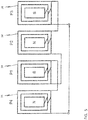
- FIG. 4 depicts the interconnection of the rotor coils and a rotary transformer 40 .
- the four rotor coils 34 of four-pole rotor assembly 30 can be series connected, parallel-connected or series-parallel-connected.
- a series connection for the rotor winding(s) 34 is employed.
- the series connected rotor windings 34 are connected to the secondary winding 42 of the rotary transformer 40.
- the fixed primary winding 44 (labeled PW) of the rotary transformer 40 is connected to the controller 50.
- the primary winding 44 is connected via a switch 60.
- the switch 60 may be electromechanical device such as a relay.
- the electromechanical switch 60 can be replaced with a solid state switch, e.g., a MOSFET.
- FIG. 5 depicts a winding arrangement for the rotor winding 34 in accordance with an embodiment.
- a PM dynamoelectric machine 100 as may be employed in the embodiments.
- discussion of the operation of a PM dynamoelectric machine 100 as a motor and generator is provided.
- a motor drive (not shown, or part of controller 50) supplies controlled multiphase electrical power to the stator winding 24.
- the rotating field in the stator coils 24 causes the rotor assembly 30 to rotate in synchronization and thereby rotate the drive shaft 10 ( FIG. 3 ).
- Fixed excitation flux provided by the PMs 37 in the rotor assembly 30 limits the use of the machine 100.
- the torque capabilities of the dynamoelectric machine 100 may readily be controlled by controlling the magnetic flux linkage ⁇ M and the q-axis armature current I aq .
- a prime mover (not shown) coupled to the drive shaft 10 rotates the PM rotor assembly 30.
- a magnetic flux linkage ( ⁇ M ) between the PMs 37 and the stator windings 24 of the stator assembly 20 the rotating magnetic field that the rotating PMs 37 generate causes magnetic excitation flux to flow through the stator winding 24, thereby generating multiphase electrical power in the stator winding 24.
- Fixed excitation flux provided by the PMs 37 in the rotor assembly 30 limits the use of the machine 100, since electromotive force (EMF) that the machine 100 generates is proportional to the rate of change of magnetic flux passing through the stator winding 20 and this rate of change is proportional to the angular velocity of the rotor assembly 30.
- EMF electromotive force
- the PM machine 100 when the PM machine 100 is initially energized, the PM machine 100 is operated as a starter. Since a PM synchronous motor is not a self-starting motor, the rotor winding 34 is employed to produce an asynchronous starting torque to ensure the PM machine 100 starts rotating. In this instance, the switch 60 is open, the series connection of rotor windings 34 is closed by the secondary winding 42 of the rotary transformer 40. The secondary winding 42 of the rotary transformer operates as an inductor.
- the back EMF equals zero and the frequency of the current in the rotor winding 34 is high, i.e., equal to the frequency of the stator current in the stator winding 24.
- the reactance of the inductor formed by the secondary winding 42 of the rotary transformer 40 is configured to also be high for the excitation frequency. This high reactance of the secondary winding 42 prevents excessive current forming in the rotor winding 34 at a back EMF equal to zero. Since the machine starts as an asynchronous motor, the current in the stator winding 24 is proportional to the current in the rotor winding 34.
- An asynchronous torque is created as a result of interaction between the current in the rotor winding 34 and rotating magnetic field produced by the current applied to the stator winding 24.
- the rotor assembly 30 begins to rotate, and the speed increases (i.e., n > 0)
- the rotor frequency decreases and the reactance of the inductor (formed by the secondary winding 42 of the rotary transformer 40) also decreases and the back EMF increases.
- the frequency in the rotor windings 34 approaches zero and the inductance from the secondary winding 42 of the rotary transformer 40 becomes negligible.
- the back EMF is at its maximum value and prevents excessive currents in the stator winding 24 and rotor winding 34.
- the reactance in the rotor winding circuitry is adjusted with the rotor speed and keeps the stator winding 24 current and rotor winding 34 current at the desired level.
- the rotor is pulled into synchronism when its speed (i.e., rotor speed is approximately equal to the synchronous speed, n ⁇ ns), the frequency of current in the rotor winding approaches zero, so the rotor winding does not participate in the production of the electromagnetic torque.
- the current in the rotor winding 34 is zero, because the PMs 37 produce the synchronous torque.
- the PM machine 100 is operated as a generator.
- the speed usually is variable (acceleration, deceleration, cruising) depending on the operation of a prime mover driving the shaft 10 of the PM machine 100.
- the magnetic flux of the PMs 37 in the rotor 30 coupling to the stator winding 24 must be controlled.
- control of the magnetic flux and coupling is facilitated by the rotating transformer 40 and the controller 50 operating as a flux diverter as described earlier.
- the controller 50 when the switch 60 is closed, the controller 50 generates a variable voltage and variable frequency excitation applied to the primary winding 44 of the rotary transformer 40.
- the excitation of the controller 50 is transformed to the secondary winding 42 of the rotary transformer 40 and feeds the rotor winding 34.
- the rotor winding 34 produces additional magnetic flux. This flux modulates the magnetic flux of PMs 37. If the speed of the drive to the PM machine 100 decreases, the magnetic flux is increased to maintain the output voltage of the PM machine 100 constant. If the speed of the prime mover driving the PM machine 100 increases, the magnetic flux is reduced to maintain the output voltage of the generator constant.
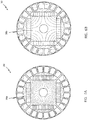
- FIGS. 6A and 6B depict a partial cross section of the rotor assembly 30 of the PM machine 100 depicting the magnetic flux lines in the rotor core 32 with magnetic flux regulation according to an embodiment.
- FIG. 6a depicts the magnetic flux lines when the control current supplied to the rotor winding 34 is zero. While FIG. 6B depicts the magnetic flux lines when the control current supplied to the rotor winding 34 is about 5 amperes and the rotor core 32 is saturated.
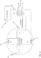
- FIG. 7 is a high-level schematic representation of an electrical power generating system 200 according to a possible embodiment. While in an embodiment the description of the systems and applications for the dynamoelectric machine 100 are made with respect to a power generation system, it should be appreciated that other configurations and systems employing the dynamoelectric machine 100 are possible and within the scope of the claims including, for example motor systems, motor control system and the like.
- the electrical power generating system may include a prime mover 48, such as an aeronautical gas turbine engine, and the PM dynamoelectric machine 100 with magnetically saturable ferromagnetic second stator 30 as described herein such as the PM dynamoelectric machine 100 as shown in FIGs. 2-6 .
- the prime mover 48 drives the machine 100, by way of a drive shaft 10.
- An auxiliary power source 51 supplies power to a control current regulator 52 by way of an auxiliary power bus 54.
- the auxiliary power source 51 may be AC or DC. It may include a multiphase AC auxiliary PM dynamoelectric machine driven by the drive shaft 2 and a multiphase AC rectifier 58 that receives multiphase AC power from the auxiliary machine 56 on a multiphase AC auxiliary power bus 60 and converts it to DC power on the auxiliary power bus 54.
- the auxiliary power source 51 may be a separately powered source or a battery with chopper shown as 51'.
- the auxiliary machine 56 may be any conventional dynamoelectric machine operable to generate power and power the auxiliary bus 54.
- the system may include a controller shown generally as 50 that may include the system sensing and control functions.
- the controller is operably connected to various sensors, such as speed and current sensors as well as provides outputs to control the system such as controllers for the current in the rotor winding 34.
- a control current regulator 52 preferably comprises an H-bridge circuit. The regulator 52 supplies control current I c to control coil(s) i.e., rotor winding 34 in the machine 100 by way of a control current supply bus 62.
- a control current sensor 64 monitors the level of control current passing through the control current supply bus 62 and generates a corresponding control current feedback signal representative of its level on a control current feedback signal line 66.
- a multiphase AC main power rectifier 68 receives multiphase AC power from the stator windings 24 of the machine 1 on a multiphase AC main power bus 70.
- the AC power is converted to DC main power on a DC main power bus 72 for supply to a DC load 74.
- a sensor detects an operating characteristic of the dynamoelectric machine 1, for example, output voltage, output current, frequency and the like. Likewise, in a motor application, operating characteristics such as motor speed, torque and the like may be measured.
- One or more main power voltage sensor(s) 76 monitor the level of voltage on the AC bus 72 and/or DC main power bus 72 and generates a corresponding voltage feedback signal (DC shown) representative of its level on a main power voltage feedback signal line 78.
- the AC power can also be converted to the DC power and then again inverted to the AC power of different frequency and different voltage level.
- a voltage signal comparator 80 receives a main power voltage reference signal on a voltage reference line 82 and compares it to the main power voltage feedback signal on the main power voltage signal line 78 to generate a voltage difference signal representative of the difference between them on a voltage difference signal line 84.
- a main power voltage feedback proportional-plus-integral (PI) controller 86 receives the voltage difference signal on the voltage difference signal line 84 and converts it to a stable control current reference signal on a control current reference signal line 88.
- PI proportional-plus-integral
- a current signal comparator 90 compares the control current reference signal on the control current reference signal line 88 with the control current feedback signal on the control current feedback signal line 66 to generate a current difference signal on a current difference signal line 92.
- a control current feedback PI controller 94 receives the current difference signal on the current difference signal line 92 and converts it to a stable control current regulating signal on a control current regulating signal line 96.
- a pulse width modulator (PWM) circuit 98 receives the control current regulating signal on a control current regulating signal line 96 and generates corresponding PWM control signals on a PWM control signal bus 99.
- a gate drive circuit 102 receives the PWM control signals on a PWM control signal bus 99 and generates corresponding gate drive signals on a gate drive signal bus 104.
- the control current regulator 52 receives the gate drive signals on the gate drive signal bus 104 to produce a level of the control current I c on the control current supply bus 62 responsive to a main power voltage feedback loop 106 and a control current feedback loop 108.
- FIG. 8 where a flowchart of the method 300 of controlling the flux in a PM dynamoelectric machine 100 is depicted.
- the method is initiated at process step 305 by providing a dynamoelectric machine 100 with a rotor assembly 30 including a rotor winding 34 in accordance with the embodiments described herein.
- an operating characteristic e.g., voltage, current output from a generator or speed, torque and the like for motor applications
- the control current I c in the rotor winding 34 is applied at process step 315 and varied to maintain the operating characteristic at a desired level as depicted at process step 320.
Landscapes
- Engineering & Computer Science (AREA)
- Power Engineering (AREA)
- Microelectronics & Electronic Packaging (AREA)
- Synchronous Machinery (AREA)
Applications Claiming Priority (1)
| Application Number | Priority Date | Filing Date | Title |
|---|---|---|---|
| US15/456,710 US20180262091A1 (en) | 2017-03-13 | 2017-03-13 | Permanent magnet starter-generator with magnetic flux regulation |
Publications (1)
| Publication Number | Publication Date |
|---|---|
| EP3376650A1 true EP3376650A1 (de) | 2018-09-19 |
Family
ID=61622379
Family Applications (1)
| Application Number | Title | Priority Date | Filing Date |
|---|---|---|---|
| EP18161018.9A Withdrawn EP3376650A1 (de) | 2017-03-13 | 2018-03-09 | Permanentmagnet-starter-generator mit magnetflussregulierung |
Country Status (2)
| Country | Link |
|---|---|
| US (1) | US20180262091A1 (de) |
| EP (1) | EP3376650A1 (de) |
Cited By (2)
| Publication number | Priority date | Publication date | Assignee | Title |
|---|---|---|---|---|
| WO2020216012A1 (zh) * | 2019-04-23 | 2020-10-29 | 山东理工大学 | 电动汽车用非对称磁极式永磁与爪极电励磁驱动电机 |
| WO2023084411A1 (en) * | 2021-11-10 | 2023-05-19 | Eldor Corporation S.P.A. | Electric motor |
Families Citing this family (22)
| Publication number | Priority date | Publication date | Assignee | Title |
|---|---|---|---|---|
| CN102097894B (zh) * | 2011-01-30 | 2012-07-25 | 陈维加 | 一种交流发电机的发电方法及其发电机 |
| CN104967378B (zh) * | 2015-05-27 | 2018-10-23 | 北京金风科创风电设备有限公司 | 风力发电机振动和噪声抑制方法及装置 |
| US11843334B2 (en) | 2017-07-13 | 2023-12-12 | Denso Corporation | Rotating electrical machine |
| JP6874675B2 (ja) | 2017-07-21 | 2021-05-19 | 株式会社デンソー | 回転電機 |
| CN113972807B (zh) | 2017-07-21 | 2023-10-27 | 株式会社电装 | 旋转电机 |
| JP6939750B2 (ja) | 2017-12-28 | 2021-09-22 | 株式会社デンソー | 回転電機 |
| DE112018006699T5 (de) | 2017-12-28 | 2020-09-10 | Denso Corporation | Rotierende elektrische Maschine |
| JP7006541B2 (ja) | 2017-12-28 | 2022-01-24 | 株式会社デンソー | 回転電機 |
| CN111512519B (zh) | 2017-12-28 | 2022-10-11 | 株式会社电装 | 旋转电机 |
| JP6922868B2 (ja) * | 2017-12-28 | 2021-08-18 | 株式会社デンソー | 回転電機システム |
| JP6927186B2 (ja) | 2017-12-28 | 2021-08-25 | 株式会社デンソー | 回転電機 |
| CN111566904B (zh) | 2017-12-28 | 2023-04-28 | 株式会社电装 | 旋转电机 |
| US11081984B2 (en) * | 2019-05-09 | 2021-08-03 | Revolution Electric Motor Company | High efficiency electronically commutated motor |
| US11177749B2 (en) * | 2018-07-27 | 2021-11-16 | Neapco Intellectual Property Holdings, Llc | System and method for rotor positioning within an electric motor |
| US20200313472A1 (en) * | 2019-03-25 | 2020-10-01 | Hamilton Sundstrand Corporation | Electric machines having cores with distributed poles |
| US11456653B2 (en) * | 2019-03-28 | 2022-09-27 | Ghsp, Inc. | Hybrid stepper motor utilizing axial coils for adjusting the magnetic field of the rotor |
| DE112020006839T5 (de) | 2020-03-05 | 2022-12-15 | Denso Corporation | Rotierende elektrische Maschinen |
| CN111614224B (zh) * | 2020-06-03 | 2024-08-06 | 黄耿正 | 永磁励磁发电机 |
| US11722021B2 (en) * | 2020-11-05 | 2023-08-08 | In Motion US, LLC | Generator for driving a predefined load |
| DE102021201602A1 (de) * | 2021-02-19 | 2022-08-25 | Zf Friedrichshafen Ag | Rotor für eine elektrische Maschine sowie elektrische Maschine mit einem Rotor |
| DE102021201603A1 (de) * | 2021-02-19 | 2022-08-25 | Zf Friedrichshafen Ag | Rotor für eine elektrische Maschine sowie elektrische Maschine mit einem Rotor |
| CN113765325A (zh) * | 2021-09-09 | 2021-12-07 | 上海电机系统节能工程技术研究中心有限公司 | 异步起动永磁同步电机及设备 |
Citations (4)
| Publication number | Priority date | Publication date | Assignee | Title |
|---|---|---|---|---|
| GB1071113A (en) * | 1963-07-05 | 1967-06-07 | Siemens Ag | Improvements in or relating to electrical machines |
| DE4139843C1 (en) * | 1991-12-03 | 1993-06-24 | Albert 7880 Bad Saeckingen De Mutter | Dynamoelectric machine, esp. for car - has salient pole laminated rotor with permanent magnets between poles plus extra slip ring-fed excitation winding |
| EP2814146A2 (de) * | 2013-06-12 | 2014-12-17 | Hamilton Sundstrand Corporation | Dauermagnetsynchronmaschinen mit magnetischer Flusssteuerung |
| EP3068033A1 (de) * | 2015-03-12 | 2016-09-14 | Hamilton Sundstrand Corporation | Steuerung von hybrider permanentmagnetmaschine mit rotierendem stromwandler und energiequelle |
Family Cites Families (7)
| Publication number | Priority date | Publication date | Assignee | Title |
|---|---|---|---|---|
| FR2774228B1 (fr) * | 1998-01-26 | 2000-04-14 | Valeo Equip Electr Moteur | Machine electrique a double excitation, et notamment alternateur de vehicule automobile |
| JP4489002B2 (ja) * | 2005-10-26 | 2010-06-23 | 三菱電機株式会社 | ハイブリッド励磁回転電機、及びハイブリッド励磁回転電機を備えた車両 |
| US8148866B2 (en) * | 2008-06-27 | 2012-04-03 | Hamilton Sundstrand Corporation | Regulated hybrid permanent magnet generator |
| US8198872B2 (en) * | 2009-03-10 | 2012-06-12 | Honeywell International, Inc. | Starter-generator with improved excitation |
| FR2945163B1 (fr) * | 2009-04-29 | 2017-06-23 | Valeo Equip Electr Moteur | Machine electrique tournante avec compensation de la reaction magnetique d'induit |
| FR2963501B1 (fr) * | 2010-07-29 | 2012-08-31 | Valeo Equip Electr Moteur | Machine electrique tournante synchrone avec rotor a double excitation |
| US20160365814A1 (en) * | 2015-06-09 | 2016-12-15 | Hamilton Sundstrand Corporation | Variable speed ac generator system including independently controlled rotor field |
-
2017
- 2017-03-13 US US15/456,710 patent/US20180262091A1/en not_active Abandoned
-
2018
- 2018-03-09 EP EP18161018.9A patent/EP3376650A1/de not_active Withdrawn
Patent Citations (4)
| Publication number | Priority date | Publication date | Assignee | Title |
|---|---|---|---|---|
| GB1071113A (en) * | 1963-07-05 | 1967-06-07 | Siemens Ag | Improvements in or relating to electrical machines |
| DE4139843C1 (en) * | 1991-12-03 | 1993-06-24 | Albert 7880 Bad Saeckingen De Mutter | Dynamoelectric machine, esp. for car - has salient pole laminated rotor with permanent magnets between poles plus extra slip ring-fed excitation winding |
| EP2814146A2 (de) * | 2013-06-12 | 2014-12-17 | Hamilton Sundstrand Corporation | Dauermagnetsynchronmaschinen mit magnetischer Flusssteuerung |
| EP3068033A1 (de) * | 2015-03-12 | 2016-09-14 | Hamilton Sundstrand Corporation | Steuerung von hybrider permanentmagnetmaschine mit rotierendem stromwandler und energiequelle |
Cited By (3)
| Publication number | Priority date | Publication date | Assignee | Title |
|---|---|---|---|---|
| WO2020216012A1 (zh) * | 2019-04-23 | 2020-10-29 | 山东理工大学 | 电动汽车用非对称磁极式永磁与爪极电励磁驱动电机 |
| US11323014B2 (en) | 2019-04-23 | 2022-05-03 | Shandong University Of Technology | Driving motor with asymmetric magnetic pole type of permanent magnet and claw pole electric excitation for electric automobile |
| WO2023084411A1 (en) * | 2021-11-10 | 2023-05-19 | Eldor Corporation S.P.A. | Electric motor |
Also Published As
| Publication number | Publication date |
|---|---|
| US20180262091A1 (en) | 2018-09-13 |
Similar Documents
| Publication | Publication Date | Title |
|---|---|---|
| EP3376650A1 (de) | Permanentmagnet-starter-generator mit magnetflussregulierung | |
| EP3346590B1 (de) | Doppelstator-permanentmagnetmaschine mit magnetflussregulierung | |
| Gao et al. | A novel hybrid excitation flux reversal machine for electric vehicle propulsion | |
| Jiao et al. | Design and control of a two-phase brushless exciter for aircraft wound-rotor synchronous starter/generator in the starting mode | |
| Wang et al. | Hybrid excitation topologies and control strategies of stator permanent magnet machines for DC power system | |
| US7134180B2 (en) | Method for providing slip energy control in permanent magnet electrical machines | |
| EP2782226B1 (de) | Flussgeregelte PM-Läufer eines elektrische Maschine | |
| JP5363913B2 (ja) | 回転電機駆動システム | |
| EP2107665A2 (de) | Dynamo-Maschine mit einem Permanentmagneten mit verstellbarer Magnetflussstimulierung | |
| EP2429063A1 (de) | Elektrische wechselstrommaschine mit klauenpolen | |
| EP2779421B1 (de) | Integrierter Startergenerator | |
| EP3316459B1 (de) | Elektromotoren | |
| EP3422541B1 (de) | Selbsterregende synchrone reluktanzgeneratoren | |
| Gagas et al. | Operating within dynamic voltage limits during magnetization state increases in variable flux PM synchronous machines | |
| EP3416268A1 (de) | Dreiphasige elektrische maschine zur flussumschaltung mit orthogonal ausgerichteten magneten | |
| US20170005555A1 (en) | Asymmetric salient permanent magnet synchronous machine | |
| JP6323220B2 (ja) | 同期電動機の駆動装置 | |
| Ishihara et al. | Improving the efficiency of switched reluctance motors using a step-skewed rotor | |
| Sulaiman et al. | Investigation of field excitation switched flux motor with segmental rotor | |
| Rallabandi et al. | Performance comparison of switched reluctance motor with sinusoidal and conventional excitation | |
| US10770999B2 (en) | Brushless, self-excited synchronous field-winding machine | |
| Jack et al. | Switched reluctance and permanent magnet motors suitable for vehicle drives-a comparison | |
| Zhou et al. | Comparative study on concentrated-windings permanent magnet synchronous machines with different rotor structures for aircraft generator application | |
| JP2004320972A (ja) | 永久磁石回転電機、永久磁石回転電機の制御方法、車両、風力発電機システム、及びエンジン発電機 | |
| Kleimaier et al. | Axial flux motor “DYNAX®”-A compact electric drive for automotive power trains |
Legal Events
| Date | Code | Title | Description |
|---|---|---|---|
| PUAI | Public reference made under article 153(3) epc to a published international application that has entered the european phase |
Free format text: ORIGINAL CODE: 0009012 |
|
| STAA | Information on the status of an ep patent application or granted ep patent |
Free format text: STATUS: THE APPLICATION HAS BEEN PUBLISHED |
|
| AK | Designated contracting states |
Kind code of ref document: A1 Designated state(s): AL AT BE BG CH CY CZ DE DK EE ES FI FR GB GR HR HU IE IS IT LI LT LU LV MC MK MT NL NO PL PT RO RS SE SI SK SM TR |
|
| AX | Request for extension of the european patent |
Extension state: BA ME |
|
| STAA | Information on the status of an ep patent application or granted ep patent |
Free format text: STATUS: REQUEST FOR EXAMINATION WAS MADE |
|
| 17P | Request for examination filed |
Effective date: 20190319 |
|
| RBV | Designated contracting states (corrected) |
Designated state(s): AL AT BE BG CH CY CZ DE DK EE ES FI FR GB GR HR HU IE IS IT LI LT LU LV MC MK MT NL NO PL PT RO RS SE SI SK SM TR |
|
| STAA | Information on the status of an ep patent application or granted ep patent |
Free format text: STATUS: EXAMINATION IS IN PROGRESS |
|
| 17Q | First examination report despatched |
Effective date: 20200123 |
|
| STAA | Information on the status of an ep patent application or granted ep patent |
Free format text: STATUS: THE APPLICATION HAS BEEN WITHDRAWN |
|
| 18W | Application withdrawn |
Effective date: 20200527 |