EP2779197A1 - Switch assembly for disconnect operator - Google Patents
Switch assembly for disconnect operator Download PDFInfo
- Publication number
- EP2779197A1 EP2779197A1 EP14159625.4A EP14159625A EP2779197A1 EP 2779197 A1 EP2779197 A1 EP 2779197A1 EP 14159625 A EP14159625 A EP 14159625A EP 2779197 A1 EP2779197 A1 EP 2779197A1
- Authority
- EP
- European Patent Office
- Prior art keywords
- switch assembly
- handle
- state
- disconnect operator
- disconnect
- Prior art date
- Legal status (The legal status is an assumption and is not a legal conclusion. Google has not performed a legal analysis and makes no representation as to the accuracy of the status listed.)
- Granted
Links
Images







Classifications
-
- H—ELECTRICITY
- H01—ELECTRIC ELEMENTS
- H01H—ELECTRIC SWITCHES; RELAYS; SELECTORS; EMERGENCY PROTECTIVE DEVICES
- H01H9/00—Details of switching devices, not covered by groups H01H1/00 - H01H7/00
- H01H9/02—Bases, casings, or covers
- H01H9/04—Dustproof, splashproof, drip-proof, waterproof, or flameproof casings
-
- H—ELECTRICITY
- H01—ELECTRIC ELEMENTS
- H01H—ELECTRIC SWITCHES; RELAYS; SELECTORS; EMERGENCY PROTECTIVE DEVICES
- H01H71/00—Details of the protective switches or relays covered by groups H01H73/00 - H01H83/00
- H01H71/04—Means for indicating condition of the switching device
-
- H—ELECTRICITY
- H01—ELECTRIC ELEMENTS
- H01H—ELECTRIC SWITCHES; RELAYS; SELECTORS; EMERGENCY PROTECTIVE DEVICES
- H01H71/00—Details of the protective switches or relays covered by groups H01H73/00 - H01H83/00
- H01H71/10—Operating or release mechanisms
- H01H71/50—Manual reset mechanisms which may be also used for manual release
- H01H71/56—Manual reset mechanisms which may be also used for manual release actuated by rotatable knob or wheel
-
- H—ELECTRICITY
- H01—ELECTRIC ELEMENTS
- H01H—ELECTRIC SWITCHES; RELAYS; SELECTORS; EMERGENCY PROTECTIVE DEVICES
- H01H9/00—Details of switching devices, not covered by groups H01H1/00 - H01H7/00
- H01H9/20—Interlocking, locking, or latching mechanisms
- H01H9/22—Interlocking, locking, or latching mechanisms for interlocking between casing, cover, or protective shutter and mechanism for operating contacts
Definitions
- the present invention is directed to disconnect operators.
- the invention is directed to water resistant actuators or switches for disconnect operators.
- an enclosure may be required to meet the UL50 type 4/IP67/IP69K standard.
- the UL50 type 4/IP67/IP69K standard provides strict guidelines within a rated device must function. The guidelines provide standards for ingress ofsolids and liquids.
- a UL50 type 4/IP67/IP69K rated device must meet a defined threshold or standard for repelling environmental conditions. Such a threshold or standard provides a challenge in adapting standard devices to meet the UL50 type 4/IP67/IP69K standard.
- Typical switch assemblies for disconnect operators include high friction, heavy duty o-rings or K-seals. These high friction seals provide the necessary rating for resistance to environmental ingress, but the switches are difficult to actuate. As a result, when an associated disconnect operator actuates to a tripped state, the switch assembly may resist the movement. Often, this problem is overcome by utilizing sealing grease or providing spring bias toward a tripped position. Typically, a handle of the switch assembly serves as the indicator of a tripped state.
- the present embodiments overcome the aforementioned problems by providing a switch assembly for a disconnect operator that is easy to assemble and that meets the UL50 type 4/IP67/IP69K standard while providing a low friction tripped state indicator.
- the invention provides a sealed switch assembly for use with a disconnect operator movable between an on state, a tripped state, and an off state.
- the disconnect operator housed within a sealed enclosure.
- the switch assembly includes a housing sealed to the enclosure to inhibit ingress of solids and liquids therebetween.
- a handle is coupled to the disconnect operator and is disposed at least partially within the housing.
- the handle is scaled to the housing to inhibit ingress of solids and liquids therebetween, and is moveable between an on position and an off position.
- a low-friction trip indicator mechanism operates independent of the handle to indicate when the disconnect operator is in the tripped state.
- the invention provides a UL50 type 4/IP67/TP69K rated switch assembly for use with a disconnect operator that is movable between an on state, a tripped state, and an off state.
- the disconnect operator is housed within a sealed enclosure.
- the switch assembly includes a handle that is coupled to the disconnect operator and is movable between an on position and an off position.
- An indicator indicates when the disconnect operator is in the tripped state, and a latching mechanism is coupled between the handle and the disconnect operator such that when the disconnect operator actuates from the on state to the tripped state, the handle does not move.
- Figs. 1 and 2 show a switch assembly 10 mounted to an enclosure 14 for operating a disconnect operator 18 located within the enclosure 14.
- the enclosure 14 defines an aperture 15, and a wall 16 that defines two apertures 17.
- the disconnect operator 18 includes a disconnect switch 22 that is moveable between an ON position, an OFF position, and a TRIPPED position (i.e., on state, off state, and tripped state). It is to be appreciated that a variety of devices are operable with the switch assembly 10.
- the switch assembly 10 includes a disconnect handle shaft 26; a low-friction trip indicator mechanism including a reset flag 30, a cam element 34, and a latching mechanism 38; a base seal 42; a housing in the form of a tagout base 46; a handle seal 50; and a handle 54.
- the tagout base 46 includes a flange 58 that defines four apertures 62 (three are visible) sized to receive fasteners for coupling the tagout base 46 to the enclosure 14 and an annular recess 66 (see Figs. 5 and 6 ) sized to receive the base seal 42.
- the illustrated base seal 42 is an o-ring, although other seal types are contemplated.
- the base seal 42 provides a static seal between the tagout base 46 and the enclosure 14 to inhibit the ingress of solids and liquid into the interior of the switch assembly 10.
- the tagout base 46 further defines an annular wall 70 surrounding a central aperture 74 arranged to align with the aperture 15 in the enclosure 14 when the tagout base 46 is installed on the enclosure 14.
- a sealing surface 78 is defined on an inner periphery of the annular wall 70 and two tagout apertures 82 are defined through the annular wall 70.
- a cutout section 86 is defined over about ninety degrees (90°) of the annular wall 70.
- the disconnect handle shaft 26 includes a base 90 defining a switch interface in the form of a recess 94 shaped to receive the disconnect switch 22 of the disconnect operator 18 when the switch assembly 10 is installed.
- a shaft 98 extends upward from the base 90 and terminates in a coupling feature in the form of two flats 102 and two keyways 106 (see Figs. 10 and 11 ).
- Fig. 9 shows an alternative disconnect handle shaft 26' with similar parts to disconnect handle shaft 26 but with a differently shaped recess 94'.
- Other profiles and switch interface features are possible and contemplated and will depend on the particular disconnect operator 18 used with the switch assembly 10.
- the reset flag 30 includes a generally circular platform 110 arranged to be supported by the enclosure, a hollow shaft 114 that extends into the enclosure 14 through the aperture 15, three engaging elements 118 arranged to engage the aperture 15 of the enclosure 14 and maintain the reset flag 30 therein, a central pole 122 extending upward from the circular platform 110, and a flag 126.
- the flag 126 defines an indication surface 130 that may be brightly colored, include text, or other indicating features, as desired.
- the flag 126 further defines a cut away portion 134.
- the interior of the hollow shaft 114 is shaped to matingly receive the coupling feature of the disconnect handle shaft 26.
- the hollow shaft 114 is arranged to engage the two flats 102 and two keyways 106 defined on the shaft 98 of the disconnect handle shaft 26.
- the hollow shaft 114 may be received within the coupling feature of the disconnect handle shaft 26 or may not be hollow.
- the latching mechanism 38 includes an upper surface 138, a first cam 142 defining a clockwise (CW) surface 146 and a counterclockwise (CCW) surface 150, a second cam 154 defining a CW surface 158 and a CCW surface 162, a first arm 166 defining a CW surface 170 and a CCW surface 174, a second arm 178 defining a CW surface 182 and a CCW surface 186, and two biasing elements in the form of living springs 190 depending downwardly from the upper surface 138, each living spring 190 defining an end face 194.
- the first arm 166 further defines a contact feature in the form of a projection or tab 198 and the second arm 178 further defines a contact feature in the form of a projection or tab 202.
- the cam element 34 includes an outer wall 206 that defines two projections 210 sized to be received within the apertures 17 formed in the wall 16 of the enclosure 14 and a ridge 214 on an interior surface.
- the cam element 34 also includes a bottom wall 218 configured to rest on top of the circular platform 110 of the reset flag 30 when the switch assembly 10 is installed.
- the bottom wall 218 defines a stop element 222.
- a first arm 226 extends upward from the bottom wall 218 and defines a cam surface 230.
- a second ann 234 extends upward from the bottom wall 218 and defines a cam surface 238.
- the cam element 34 further defines an OFF surface 242 and an ON surface 246.
- the handle 54 includes a hand grip portion 250, an outer wall 254 that defines two tagout channels 258, 262 positioned to cooperate with the apertures 17 of the enclosure 14 for tagging out the disconnect operator 18 in the OFF position.
- the handle 54 further includes top wall 266 with a window 270 formed therethrough.
- the window 270 is formed of a clear material that may have magnifying properties.
- a recess 274 is formed in the handle 54 and arranged to receive the handle seal 50 (e.g., an o-ring) and hold it in place against the sealing surface 78 of the tagout base 46.
- Four engagement elements 278 are configured to maintain the handle 54 installed within the tagout base 46.
- the handle seal 50 provides a continuous radial seal, allowing the handle 54 to rotate while maintaining a seal.
- the base seal 42 and the handle seal 50 cooperate to provide environmental protection that meets the UL50 type 4/IP67/IP69K standard.
- the handle 54 further includes a first tab 282 formed on the underside of the top wall 266 and defining a CW ramp 286 and a CCW surface 290, a second tab 294 that defines a CW surface 298 and a CCW surface 302, and a third tab 306 that defines a CW surface 310 and a CCW surface 314.
- the disconnect operator 18 is in the ON position and, correspondingly, the switch assembly 10 is in an ON position.
- the disconnect handle shaft 26 is rotated fully CW.
- the flag 126 of the reset flag 30 is rotated CW until the flag 126 abuts the ON surface 246 of the cam element 34.
- the flag 30 abuts and holds the CCW surface 290 of the handle's 54 first tab 282 rotated fully CW.
- the tabs 198, 202 of the latching mechanism 38 are engaged with the cam surfaces 230, 238 of the cam element 34 such that the upper surface 138 of the latching mechanism 38 is forced downward out of engagement with the tabs 282, 294, 306 of the handle 54. Additionally, the end face 194 one living spring 190 abuts the stop element 222 of the cam element 34.
- Fig. 25 the switch assembly 10 is shown in a TRIPPED position.
- switch 22 rotates forty-five degrees (45°) CCW.
- the flag 126 is likewise rotated CCW forty-five degrees (45°) and rotates the latching mechanism 38 therewith by abutting the CW surface 146 of the first cam 142.
- the CCW rotation of the latching mechanism 38 frees the tabs 198, 202 from the cam surfaces 230, 238 of the cam element 34 and the living springs 190 bias the upper surface 138 upward toward the handle 54.
- the handle 54 does not move. However, a user is given a clear indication that the disconnect operator 18 is in the TRIPPED position via the indicator surface 130 of the flag 126 showing clearly through the window 270 of the handle 54.
- Fig. 26 the switch assembly 10 is shown in an OFF position.
- the disconnect operator 18 After the disconnect operator 18 has moved to the TRIPPED position, it must be forced into the OFF position before it can be reset to the ON position.
- the handle 54 To move the disconnect operator 18 to the OFF position, the handle 54 is rotated CCW ninety degrees (90°). The handle 54 rotates freely for the first forty-five degrees (45°) until the first tab 282 abuts the flag 126. Further CCW rotation of the handle 54 forces the flag 126 to the position shown in Fig. 26 wherein the flag 126 is fully rotated CCW and the cut away portion 134 abuts the OFF surface 242 of the cam element 34.
- the switch assembly 10 is shown in a RESET position in which the components are in the same positions as in the ON position.
- the disconnect operator 18 may be reset to the ON position.
- the handle 54 With the tabs 282, 294, 302 of the handle 54, the flag 126, and the cams 142, 154 of the latching mechanism 38 engaged and the tabs 198, 202 of the latching mechanism 38 removed from the cam surfaces 230, 238 of the cam element 34, the handle 54 is rotated CW ninety degrees (90°) such that the second tab 294 pushes on the CCW surface 150 of the latching mechanism's 38 first cam 142, the third tab 306 pushes on the CCW surface 162 of the latching mechanism's 38 second cam 154, and the CW surface 146 of the first cam 142 pushes on the flag 126.
- the switching assembly 10 moved back into the ON position, or, in this case, the RESET position.
- the tabs 198, 202 reengage the cam surfaces 230 238 of the cam element 34 such that the upper surface 138 of the latching mechanism 38 is again lowered below the plane of the tabs 282, 294, 302 against the bias of the living springs 190.
- the switch assembly 10 may be assembled without k-seals, scaling grease and still maintain a UL50 type 4/IP67/IP69K standard rating.
- the switch assembly 10 is assembled via snap fit to trap the internal components without the use of screws, staking, sealing greases, springs, or any other mechanical fastening methods.
- the switch assembly 10 can be turned off, reset, and turned back on while maintaining the required environmental seal.
- the switching assembly 10 provides a user with a clear indication that the disconnect operator 18 is in the TRIPPED position while maintaining the required environmental seal.
- the handle 54 docs not move when the disconnect operator 18 moves from the ON position to the TRIPPED position, there is very little resistance to movement of the disconnect operator 18 or the components that indicate a tripped state.
- the components that indicate a tripped state provide an indication of a tripped disconnect operator 18 substantially instantly.
- the spring force of the disconnect operator's 18 disconnect switch 22 operates the trip mechanism (e.g., the indication surface 130 of the flag 126 and the window 270) of the switch assembly 10 freely.
- the switch assembly 10 provides a lockout tagout ability while maintaining the required environmental seal.
- switch assembly 14 enclosure 15 aperture 16 wall 17 two apertures 18 disconnect operator 22 disconnect switch 26 disconnect handle shaft 26' alternative disconnect handle shaft 30 reset flag 34 cam element 38 latching mechanism 30, 34, 38 low-friction trip indicator mechanism 42 base seal 46 housing in the form of a tagout base 50 handle seal 54 handle 58 flange 62 four aperture 66 annular recess 70 annular wall 74 central aperture 78 sealing surface 82 two tagout apertures 86 cutout section 90 base 94 recess 94' differently shaped recess 98 shaft 102 two flats 106 two keyways 110 generally circular platform 114 hollow shaft 118 three engaging elements 122 central pole 126 flag 130 indication surface 134 cut away portion 138 upper surface 142 first cam 146 clockwise (CW) surface 150 counterclockwise (CCW) surface 154 second cam 158 CW surface 162 CCW surface 166 first arm 170 CW surface 174 CCW surface 178 second arm 182 CW surface 186 CCW surface 190 living springs 194 end face
Landscapes
- Switch Cases, Indication, And Locking (AREA)
Abstract
Description
- This application claims the benefit of
U.S. Patent Application No. 13/337,100, filed March 15, 2013 - The present invention is directed to disconnect operators. In particular the invention is directed to water resistant actuators or switches for disconnect operators.
- In industrial environments, electrical enclosures and related components need to meet various standards based on the environment the electrical enclosure will be subjected to. For example, an enclosure may be required to meet the UL50 type 4/IP67/IP69K standard. The UL50 type 4/IP67/IP69K standard provides strict guidelines within a rated device must function. The guidelines provide standards for ingress ofsolids and liquids. As a result, a UL50 type 4/IP67/IP69K rated device must meet a defined threshold or standard for repelling environmental conditions. Such a threshold or standard provides a challenge in adapting standard devices to meet the UL50 type 4/IP67/IP69K standard.
- Typical switch assemblies for disconnect operators include high friction, heavy duty o-rings or K-seals. These high friction seals provide the necessary rating for resistance to environmental ingress, but the switches are difficult to actuate. As a result, when an associated disconnect operator actuates to a tripped state, the switch assembly may resist the movement. Often, this problem is overcome by utilizing sealing grease or providing spring bias toward a tripped position. Typically, a handle of the switch assembly serves as the indicator of a tripped state.
- The present embodiments overcome the aforementioned problems by providing a switch assembly for a disconnect operator that is easy to assemble and that meets the UL50 type 4/IP67/IP69K standard while providing a low friction tripped state indicator.
- In one construction, the invention provides a sealed switch assembly for use with a disconnect operator movable between an on state, a tripped state, and an off state. The disconnect operator housed within a sealed enclosure. The switch assembly includes a housing sealed to the enclosure to inhibit ingress of solids and liquids therebetween. A handle is coupled to the disconnect operator and is disposed at least partially within the housing. The handle is scaled to the housing to inhibit ingress of solids and liquids therebetween, and is moveable between an on position and an off position. A low-friction trip indicator mechanism operates independent of the handle to indicate when the disconnect operator is in the tripped state.
- In another construction, the invention provides a UL50 type 4/IP67/TP69K rated switch assembly for use with a disconnect operator that is movable between an on state, a tripped state, and an off state. The disconnect operator is housed within a sealed enclosure. The switch assembly includes a handle that is coupled to the disconnect operator and is movable between an on position and an off position. An indicator indicates when the disconnect operator is in the tripped state, and a latching mechanism is coupled between the handle and the disconnect operator such that when the disconnect operator actuates from the on state to the tripped state, the handle does not move.
- The invention will be better understood and features, aspects and advantages other than those set forth above will become apparent when consideration is given to the following detailed description thereof. Such detailed description makes reference to the following drawings.
-
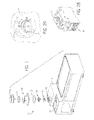
Fig. 1 is an exploded view of a switch assembly according to one embodiment of the invention installed in an enclosure. -
Fig. 2 is a section view of the exploded switch assembly ofFig. 1 taken along line 2-2 ofFig. 1 . -
Fig. 3 is an exploded view of the switch assembly ofFig. 1 . -
Fig. 4 is a section view of the exploded switch assembly ofFig. 1 taken along line 4-4 ofFig. 1 . -
Fig. 5 is a section view of the switch assembly ofFig. 1 installed in the enclosure. -
Fig. 6 is a section view of the switch assembly ofFig. 1 installed in the enclosure. -
Fig. 7 is a perspective view of a tag out base of the switch assembly ofFig. 1 . -
Fig. 8 is a bottom perspective view of a disconnect handle shaft of the switch assembly ofFig. 1 . -
Fig. 9 is a bottom perspective view of another disconnect handle shaft. -
Fig. 10 is a top perspective view of the disconnect handle shaft ofFig. 8 . -
Fig. 11 is a top view of the disconnect handle shaft ofFig. 8 . -
Fig. 12 is a top perspective view of a reset flag of the switch assembly ofFig. 1 . -
Fig. 13 is another top perspective view of the reset flag ofFig. 12 . -
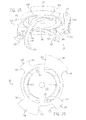
Fig. 14 is a top perspective view of a latching mechanism of the switch assembly ofFig. 1 . -
Fig. 15 is a bottom perspective view of the latching mechanism ofFig. 14 . -
Fig. 16 is a top view of the latching mechanism ofFig. 14 . -
Fig. 17 is a bottom view of the latching mechanism ofFig. 14 . -
Fig. 18 is a top perspective view of a cam element of the switch assembly ofFig. 1 . -
Fig. 19 is a bottom view of the cam element ofFig. 18 . -
Fig. 20 is a top view of the cam element ofFig. 18 . -
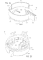
Fig. 21 is a top perspective view of a handle of the switch assembly ofFig. 1 . -
Fig. 22 is a bottom perspective view of the handle ofFig. 21 . -
Fig. 23 is a top view of the handle ofFig. 21 . -
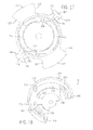
Fig. 24 is a plan view showing the switch assembly ofFig. 1 in an ON position. -
Fig. 25 is a plan view showing the switch assembly ofFig. 1 in a TRIPPED position. -
Fig. 26 is a plan view showing the switch assembly ofFig. 1 in an OFF position. -
Fig. 27 is a plan view showing the switch assembly ofFig. 1 in a RESET position. -
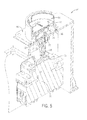
Fig. 28 is a perspective view of a disconnect operator. -
Fig. 29 is a detail view of a connection point of the enclosure ofFig. 1 . - While the invention is susceptible to various modifications and alternative forms, specific embodiments thereof have been shown by way of example in the drawings and are herein described in detail. It should be understood, however, that the description herein of specific embodiments is not intended to limit the invention to the particular forms disclosed, but on the contrary, the intention is to cover all modifications, equivalents, and alternatives falling within the spirit and scope of the invention as defined by the appended claims.
- The present invention will be described in terms of one or more preferred embodiments, and it should be appreciated that many equivalents, alternatives, variations, and modifications, aside from those expressly stated, are possible and within the scope of the invention.
-
Figs. 1 and2 show aswitch assembly 10 mounted to anenclosure 14 for operating adisconnect operator 18 located within theenclosure 14. As shown inFig. 29 , theenclosure 14 defines anaperture 15, and awall 16 that defines twoapertures 17. As shown inFig. 28 , thedisconnect operator 18 includes adisconnect switch 22 that is moveable between an ON position, an OFF position, and a TRIPPED position (i.e., on state, off state, and tripped state). It is to be appreciated that a variety of devices are operable with theswitch assembly 10. - Turning to
Figs. 3-6 , theswitch assembly 10 includes adisconnect handle shaft 26; a low-friction trip indicator mechanism including areset flag 30, acam element 34, and alatching mechanism 38; abase seal 42; a housing in the form of atagout base 46; ahandle seal 50; and ahandle 54. - With reference to
Fig. 7 , thetagout base 46 includes aflange 58 that defines four apertures 62 (three are visible) sized to receive fasteners for coupling thetagout base 46 to theenclosure 14 and an annular recess 66 (seeFigs. 5 and6 ) sized to receive thebase seal 42. The illustratedbase seal 42 is an o-ring, although other seal types are contemplated. Thebase seal 42 provides a static seal between thetagout base 46 and theenclosure 14 to inhibit the ingress of solids and liquid into the interior of theswitch assembly 10. - The
tagout base 46 further defines anannular wall 70 surrounding acentral aperture 74 arranged to align with theaperture 15 in theenclosure 14 when thetagout base 46 is installed on theenclosure 14. A sealingsurface 78 is defined on an inner periphery of theannular wall 70 and twotagout apertures 82 are defined through theannular wall 70. A cutout section 86 is defined over about ninety degrees (90°) of theannular wall 70. - With reference to
Figs. 8 ,10 , and11 , thedisconnect handle shaft 26 includes a base 90 defining a switch interface in the form of arecess 94 shaped to receive thedisconnect switch 22 of thedisconnect operator 18 when theswitch assembly 10 is installed. Ashaft 98 extends upward from thebase 90 and terminates in a coupling feature in the form of twoflats 102 and two keyways 106 (seeFigs. 10 and11 ). -
Fig. 9 shows an alternative disconnect handle shaft 26' with similar parts to disconnecthandle shaft 26 but with a differently shaped recess 94'. Other profiles and switch interface features are possible and contemplated and will depend on theparticular disconnect operator 18 used with theswitch assembly 10. - With reference to
Figs. 12 and13 , thereset flag 30 includes a generallycircular platform 110 arranged to be supported by the enclosure, ahollow shaft 114 that extends into theenclosure 14 through theaperture 15, threeengaging elements 118 arranged to engage theaperture 15 of theenclosure 14 and maintain thereset flag 30 therein, acentral pole 122 extending upward from thecircular platform 110, and aflag 126. Theflag 126 defines anindication surface 130 that may be brightly colored, include text, or other indicating features, as desired. Theflag 126 further defines a cut awayportion 134. - The interior of the
hollow shaft 114 is shaped to matingly receive the coupling feature of thedisconnect handle shaft 26. In the present embodiment, thehollow shaft 114 is arranged to engage the twoflats 102 and twokeyways 106 defined on theshaft 98 of thedisconnect handle shaft 26. In other embodiments, thehollow shaft 114 may be received within the coupling feature of thedisconnect handle shaft 26 or may not be hollow. - With reference to
Figs. 14-17 , thelatching mechanism 38 includes anupper surface 138, afirst cam 142 defining a clockwise (CW)surface 146 and a counterclockwise (CCW)surface 150, asecond cam 154 defining aCW surface 158 and aCCW surface 162, afirst arm 166 defining aCW surface 170 and aCCW surface 174, asecond arm 178 defining aCW surface 182 and aCCW surface 186, and two biasing elements in the form of living springs 190 depending downwardly from theupper surface 138, each livingspring 190 defining anend face 194. Thefirst arm 166 further defines a contact feature in the form of a projection ortab 198 and thesecond arm 178 further defines a contact feature in the form of a projection ortab 202. - With reference to
Figs. 18-20 , thecam element 34 includes anouter wall 206 that defines twoprojections 210 sized to be received within theapertures 17 formed in thewall 16 of theenclosure 14 and aridge 214 on an interior surface. Thecam element 34 also includes abottom wall 218 configured to rest on top of thecircular platform 110 of thereset flag 30 when theswitch assembly 10 is installed. Thebottom wall 218 defines astop element 222. Afirst arm 226 extends upward from thebottom wall 218 and defines acam surface 230. Asecond ann 234 extends upward from thebottom wall 218 and defines acam surface 238. Thecam element 34 further defines anOFF surface 242 and anON surface 246. - With reference to
Figs. 21-23 , thehandle 54 includes ahand grip portion 250, anouter wall 254 that defines twotagout channels apertures 17 of theenclosure 14 for tagging out thedisconnect operator 18 in the OFF position. Thehandle 54 further includestop wall 266 with awindow 270 formed therethrough. Thewindow 270 is formed of a clear material that may have magnifying properties. Arecess 274 is formed in thehandle 54 and arranged to receive the handle seal 50 (e.g., an o-ring) and hold it in place against the sealingsurface 78 of thetagout base 46. Fourengagement elements 278 are configured to maintain thehandle 54 installed within thetagout base 46. Thehandle seal 50 provides a continuous radial seal, allowing thehandle 54 to rotate while maintaining a seal. Thebase seal 42 and thehandle seal 50 cooperate to provide environmental protection that meets the UL50 type 4/IP67/IP69K standard. - Turning to
Fig. 22 , thehandle 54 further includes afirst tab 282 formed on the underside of thetop wall 266 and defining aCW ramp 286 and aCCW surface 290, asecond tab 294 that defines aCW surface 298 and aCCW surface 302, and athird tab 306 that defines aCW surface 310 and aCCW surface 314. - Operation of the
switch assembly 10 will be discussed below with reference toFigs. 24-27 . Turning particularly toFig. 24 , thedisconnect operator 18 is in the ON position and, correspondingly, theswitch assembly 10 is in an ON position. When theswitch assembly 10 is in the ON position, thedisconnect handle shaft 26 is rotated fully CW. As a result, theflag 126 of thereset flag 30 is rotated CW until theflag 126 abuts theON surface 246 of thecam element 34. Theflag 30 abuts and holds theCCW surface 290 of the handle's 54first tab 282 rotated fully CW. When theswitch assembly 10 is in the ON position, thetabs latching mechanism 38 are engaged with the cam surfaces 230, 238 of thecam element 34 such that theupper surface 138 of thelatching mechanism 38 is forced downward out of engagement with thetabs handle 54. Additionally, theend face 194 oneliving spring 190 abuts thestop element 222 of thecam element 34. - Turning to
Fig. 25 , theswitch assembly 10 is shown in a TRIPPED position. When thedisconnect operator 18 moves from the ON position to the TRIPPED position, switch 22 rotates forty-five degrees (45°) CCW. Theflag 126 is likewise rotated CCW forty-five degrees (45°) and rotates thelatching mechanism 38 therewith by abutting theCW surface 146 of thefirst cam 142. The CCW rotation of thelatching mechanism 38 frees thetabs cam element 34 and the living springs 190 bias theupper surface 138 upward toward thehandle 54. In moving from the ON position to the TRIPPED position, thehandle 54 does not move. However, a user is given a clear indication that thedisconnect operator 18 is in the TRIPPED position via theindicator surface 130 of theflag 126 showing clearly through thewindow 270 of thehandle 54. - Turning to
Fig. 26 , theswitch assembly 10 is shown in an OFF position. After thedisconnect operator 18 has moved to the TRIPPED position, it must be forced into the OFF position before it can be reset to the ON position. To move thedisconnect operator 18 to the OFF position, thehandle 54 is rotated CCW ninety degrees (90°). Thehandle 54 rotates freely for the first forty-five degrees (45°) until thefirst tab 282 abuts theflag 126. Further CCW rotation of thehandle 54 forces theflag 126 to the position shown inFig. 26 wherein theflag 126 is fully rotated CCW and the cut awayportion 134 abuts theOFF surface 242 of thecam element 34. The rotation of theflag 126 forces the latchingmechanism 38 to continue rotating to the position shown inFig. 26 wherein thecams arms tabs handle 54 and the living springs 190 bias theupper surface 138 upward into the same plane as thetabs - Turning to
Fig. 27 , theswitch assembly 10 is shown in a RESET position in which the components are in the same positions as in the ON position. After thedisconnect operator 18 is moved to the OFF position, it may be reset to the ON position. With thetabs handle 54, theflag 126, and thecams latching mechanism 38 engaged and thetabs latching mechanism 38 removed from the cam surfaces 230, 238 of thecam element 34, thehandle 54 is rotated CW ninety degrees (90°) such that thesecond tab 294 pushes on theCCW surface 150 of the latching mechanism's 38first cam 142, thethird tab 306 pushes on theCCW surface 162 of the latching mechanism's 38second cam 154, and theCW surface 146 of thefirst cam 142 pushes on theflag 126. In this way, the switchingassembly 10 moved back into the ON position, or, in this case, the RESET position. While thelatching mechanism 38 is being rotated, thetabs cam element 34 such that theupper surface 138 of thelatching mechanism 38 is again lowered below the plane of thetabs - The invention offers several advantages. First, the
switch assembly 10 may be assembled without k-seals, scaling grease and still maintain a UL50 type 4/IP67/IP69K standard rating. Second, theswitch assembly 10 is assembled via snap fit to trap the internal components without the use of screws, staking, sealing greases, springs, or any other mechanical fastening methods. Third, theswitch assembly 10 can be turned off, reset, and turned back on while maintaining the required environmental seal. Fourth, by using theindicator surface 130 visible through thewindow 270, the switchingassembly 10 provides a user with a clear indication that thedisconnect operator 18 is in the TRIPPED position while maintaining the required environmental seal. Fifth, because thehandle 54 docs not move when thedisconnect operator 18 moves from the ON position to the TRIPPED position, there is very little resistance to movement of thedisconnect operator 18 or the components that indicate a tripped state. The components that indicate a tripped state provide an indication of a trippeddisconnect operator 18 substantially instantly. In other words, the spring force of the disconnect operator's 18disconnect switch 22 operates the trip mechanism (e.g., theindication surface 130 of theflag 126 and the window 270) of theswitch assembly 10 freely. Sixth, theswitch assembly 10 provides a lockout tagout ability while maintaining the required environmental seal. - Other embodiments are possible in view of the following claims.
10 switch assembly 14 enclosure 15 aperture 16 wall 17 two apertures 18 disconnect operator 22 disconnect switch 26 disconnect handle shaft 26' alternative disconnect handle shaft 30 reset flag 34 cam element 38 latching mechanism 30, 34, 38 low-friction trip indicator mechanism 42 base seal 46 housing in the form of a tagout base 50 handle seal 54 handle 58 flange 62 four aperture 66 annular recess 70 annular wall 74 central aperture 78 sealing surface 82 two tagout apertures 86 cutout section 90 base 94 recess 94' differently shaped recess 98 shaft 102 two flats 106 two keyways 110 generally circular platform 114 hollow shaft 118 three engaging elements 122 central pole 126 flag 130 indication surface 134 cut away portion 138 upper surface 142 first cam 146 clockwise (CW) surface 150 counterclockwise (CCW) surface 154 second cam 158 CW surface 162 CCW surface 166 first arm 170 CW surface 174 CCW surface 178 second arm 182 CW surface 186 CCW surface 190 living springs 194 end face 198 first arm 166 further defines a contact feature in the form of a projection or tab 202 the second arm 178 further defines a contact feature in the form of a projection or tab 206 outer wall 210 two projections 214 ridge 218 bottom wall 222 stop element 226 first arm 230 cam surface 234 second arm 238 cam surface 242 OFF surface 246 ON surface 250 hand grip portion 254 outer wall 258 tagout channels 262 tagout channels 266 top wall 270 window 274 recess 278 Four engagement elements 282 first tab 286 CW ramp 290 CCW surface 294 second tab 298 CW surface 302 CCW surface 306 third tab 310 CW surface 314 CCW surface
Claims (15)
- A sealed switch assembly (10) for use with a disconnect operator (18) movable between an on state, a tripped state, and an off state, the disconnect operator housed within a sealed enclosure (14), the switch assembly comprising:a housing (46) sealed to the enclosure to inhibit ingress of solids and liquids therebetween;a handle (54) coupled to the disconnect operator and disposed at least partially within the housing, the handle sealed to the housing to inhibit ingress of solids and liquids therebetween, the handle moveable between an on position and an off position; anda low-friction trip indicator mechanism (30, 34, 38) that operates independent of the handle to indicate when the disconnect operator is in the tripped state.
- The switch assembly of claim 1, wherein the switch assembly meets a UL50 type 4/IP67/IP69K standard.
- The switch assembly of claim 1, wherein the handle does not move when the disconnect operator switches from the on state to the tripped state.
- The switch assembly of claim 1, wherein the handle rotates between the on position and the off position.
- The switch assembly of claim 1, wherein the low-friction trip indicator mechanism includes a flag coupled to the disconnect operator and that moves in response to the disconnect operator switching between the on state and the tripped state.
- The switch assembly of claim 5, wherein the low-friction trip indicator mechanism further includes a window formed in the handle, the flag visible through the window when the disconnect operator is in the tripped state.
- The switch assembly of claim 1, wherein the handle is operable to actuate the disconnect operator to the off state and the on state.
- The switch assembly of claim 1, wherein the disconnect operator includes a switch that rotates about forty-five degrees when the disconnect operator actuates between the on state and the off state, and
wherein the low-friction trip indicator mechanism is operable to indicate that the switch has rotated. - The switch assembly of claim 1, wherein the low-friction trip indicator mechanism is coupled between the handle and the disconnect operator such that when the disconnect operator is in the tripped state, the handle must be moved to the off position before the disconnect operator can be actuated to the on state.
- The switch assembly of claim 1, wherein the low-friction trip indicator mechanism includes a flag and the handle includes a window through which the flag is visible when the disconnect operator is in the tripped state.
- The switch assembly of claim 1, wherein the low-friction trip indicator mechanism interacts with the handle.
- The switch assembly of claim 1, wherein the low-friction trip indicator mechanism is at least partially positioned within the housing.
- The switch assembly of claim 12, further comprising an o-ring positioned between the housing and the enclosure to inhibit ingress of environmental elements and an o-ring positioned between the housing and the handle to inhibit ingress of environmental elements.
- The switch assembly of claim 11, wherein the disconnect operator includes a switch that rotates about forty-five degrees when the disconnect operator actuates between the on state and the off state, and
wherein the low-friction trip indicator mechanism is operable to indicate that the switch has rotated. - A method of indicating when a disconnect operator is in a tripped state using a sealed switch assembly according to any one of claims 1 to 14.
Applications Claiming Priority (1)
| Application Number | Priority Date | Filing Date | Title |
|---|---|---|---|
| US13/837,100 US9390868B2 (en) | 2013-03-15 | 2013-03-15 | Switch assembly for disconnect operator |
Publications (2)
| Publication Number | Publication Date |
|---|---|
| EP2779197A1 true EP2779197A1 (en) | 2014-09-17 |
| EP2779197B1 EP2779197B1 (en) | 2016-07-06 |
Family
ID=50272468
Family Applications (1)
| Application Number | Title | Priority Date | Filing Date |
|---|---|---|---|
| EP14159625.4A Not-in-force EP2779197B1 (en) | 2013-03-15 | 2014-03-13 | Switch assembly for disconnect operator |
Country Status (3)
| Country | Link |
|---|---|
| US (1) | US9390868B2 (en) |
| EP (1) | EP2779197B1 (en) |
| CN (1) | CN104051168B (en) |
Families Citing this family (6)
| Publication number | Priority date | Publication date | Assignee | Title |
|---|---|---|---|---|
| US11557443B2 (en) * | 2020-05-26 | 2023-01-17 | Rockwell Automation Switzerland Gmbh | Door handle coupler |
| CN111863553B (en) * | 2020-07-07 | 2025-06-10 | 浙江正泰电器股份有限公司 | Indicating device for switch electric appliance |
| GB2606588A (en) * | 2021-05-12 | 2022-11-16 | Eaton Intelligent Power Ltd | Device for disconnecting an electrical circuit |
| US20240234054A1 (en) * | 2021-05-12 | 2024-07-11 | Eaton Intelligent Power Limited | Device for disconnecting an electrical circuit |
| US12342485B2 (en) * | 2021-11-05 | 2025-06-24 | Eaton Intelligent Power Limited | Motor control center buckets with interlocked cover-mounted power disconnect switch mechanisms |
| US12537150B2 (en) * | 2022-09-15 | 2026-01-27 | Uno Minda Limited | Switching unit for a vehicle |
Citations (3)
| Publication number | Priority date | Publication date | Assignee | Title |
|---|---|---|---|---|
| US3911235A (en) * | 1974-04-29 | 1975-10-07 | Square D Co | Flange mounted operator for an enclosed electric circuit breaker |
| DE4312428C1 (en) * | 1993-04-19 | 1994-11-03 | Kloeckner Moeller Gmbh | Manual operating device for encapsulated electrical switching devices |
| DE20313193U1 (en) * | 2003-08-20 | 2003-10-30 | Siemens AG, 80333 München | Three phase driver for an electric rocker switch with a spring to move the switch past its dead point |
Family Cites Families (9)
| Publication number | Priority date | Publication date | Assignee | Title |
|---|---|---|---|---|
| US2306235A (en) * | 1941-08-06 | 1942-12-22 | Gen Electric | Circuit breaker |
| US5817999A (en) * | 1995-01-13 | 1998-10-06 | Square D Company | Circuit breaker operating handle locking device |
| US6008458A (en) * | 1998-03-30 | 1999-12-28 | C & K Components, Inc. | Sealed slide switch |
| JP4735418B2 (en) | 2006-05-29 | 2011-07-27 | 富士電機機器制御株式会社 | External circuit handle device for circuit breaker |
| JP4867644B2 (en) | 2006-12-26 | 2012-02-01 | 富士電機機器制御株式会社 | External circuit handle device for circuit breaker |
| US8519283B2 (en) * | 2010-01-20 | 2013-08-27 | Eaton Corporation | Cover assembly with electrical switching apparatus |
| EP2410550B1 (en) * | 2010-07-23 | 2016-08-17 | Eaton Electrical IP GmbH & Co. KG | Lockable rotary handle |
| EP2463875A1 (en) * | 2010-12-13 | 2012-06-13 | Eaton Industries GmbH | Closable manually activated rotary drive for electric switching devices |
| CN102867674B (en) | 2011-07-08 | 2015-10-28 | 海洋王照明科技股份有限公司 | Circuit switch controller |
-
2013
- 2013-03-15 US US13/837,100 patent/US9390868B2/en active Active
-
2014
- 2014-03-13 EP EP14159625.4A patent/EP2779197B1/en not_active Not-in-force
- 2014-03-17 CN CN201410098741.8A patent/CN104051168B/en not_active Expired - Fee Related
Patent Citations (3)
| Publication number | Priority date | Publication date | Assignee | Title |
|---|---|---|---|---|
| US3911235A (en) * | 1974-04-29 | 1975-10-07 | Square D Co | Flange mounted operator for an enclosed electric circuit breaker |
| DE4312428C1 (en) * | 1993-04-19 | 1994-11-03 | Kloeckner Moeller Gmbh | Manual operating device for encapsulated electrical switching devices |
| DE20313193U1 (en) * | 2003-08-20 | 2003-10-30 | Siemens AG, 80333 München | Three phase driver for an electric rocker switch with a spring to move the switch past its dead point |
Also Published As
| Publication number | Publication date |
|---|---|
| CN104051168A (en) | 2014-09-17 |
| US9390868B2 (en) | 2016-07-12 |
| CN104051168B (en) | 2017-05-10 |
| EP2779197B1 (en) | 2016-07-06 |
| US20140262711A1 (en) | 2014-09-18 |
Similar Documents
| Publication | Publication Date | Title |
|---|---|---|
| US9390868B2 (en) | Switch assembly for disconnect operator | |
| EP2849200B1 (en) | Remote operated circuit breaker with manual reset | |
| EP2725601B1 (en) | Remote operated circuit breaker | |
| US3367206A (en) | Pushbutton actuator | |
| EP3318163B1 (en) | Excess pressure protection switch and pressure appliance provided with same | |
| US8766126B2 (en) | Operation switch | |
| US8593241B2 (en) | Enclosed proximity switch assembly | |
| US7855345B2 (en) | Differential pressure switch | |
| CN105610058A (en) | Switch apparatus for enclosures having environmental protection | |
| US20050133348A1 (en) | Padlockable push-button | |
| US3720899A (en) | Thermostat with overlaod indicator | |
| US8587395B2 (en) | Rotary encoder switch with pull function tactile feedback and positive stop | |
| US10242824B2 (en) | Lockout device for switchgear | |
| CA3116602A1 (en) | Electrical switching apparatus and trip assembly therefor | |
| CN111095456B (en) | Operating accessory | |
| US9679709B2 (en) | Devices and methods for activating circuit breaker accessories | |
| US12154733B2 (en) | Transmission assembly for switchbox | |
| CN108400031B (en) | Limit switch reset key | |
| EP4250324A1 (en) | Rotary lockout tagout latch system | |
| US11984709B2 (en) | Actuator for a switch gear of an electric panel | |
| US20050230229A1 (en) | Indexing mechanism | |
| US20250157771A1 (en) | Circuit breaker interlock mechanism | |
| WO2023055590A1 (en) | Transmission assembly for switchbox |
Legal Events
| Date | Code | Title | Description |
|---|---|---|---|
| 17P | Request for examination filed |
Effective date: 20140313 |
|
| AK | Designated contracting states |
Kind code of ref document: A1 Designated state(s): AL AT BE BG CH CY CZ DE DK EE ES FI FR GB GR HR HU IE IS IT LI LT LU LV MC MK MT NL NO PL PT RO RS SE SI SK SM TR |
|
| AX | Request for extension of the european patent |
Extension state: BA ME |
|
| PUAI | Public reference made under article 153(3) epc to a published international application that has entered the european phase |
Free format text: ORIGINAL CODE: 0009012 |
|
| R17P | Request for examination filed (corrected) |
Effective date: 20150317 |
|
| RBV | Designated contracting states (corrected) |
Designated state(s): AL AT BE BG CH CY CZ DE DK EE ES FI FR GB GR HR HU IE IS IT LI LT LU LV MC MK MT NL NO PL PT RO RS SE SI SK SM TR |
|
| REG | Reference to a national code |
Ref country code: DE Ref legal event code: R079 Ref document number: 602014002537 Country of ref document: DE Free format text: PREVIOUS MAIN CLASS: H01H0071040000 Ipc: H01H0009040000 |
|
| GRAP | Despatch of communication of intention to grant a patent |
Free format text: ORIGINAL CODE: EPIDOSNIGR1 |
|
| RIC1 | Information provided on ipc code assigned before grant |
Ipc: H01H 71/04 20060101ALI20160310BHEP Ipc: H01H 9/22 20060101ALI20160310BHEP Ipc: H01H 9/04 20060101AFI20160310BHEP Ipc: H01H 71/56 20060101ALI20160310BHEP |
|
| INTG | Intention to grant announced |
Effective date: 20160323 |
|
| GRAS | Grant fee paid |
Free format text: ORIGINAL CODE: EPIDOSNIGR3 |
|
| GRAA | (expected) grant |
Free format text: ORIGINAL CODE: 0009210 |
|
| AK | Designated contracting states |
Kind code of ref document: B1 Designated state(s): AL AT BE BG CH CY CZ DE DK EE ES FI FR GB GR HR HU IE IS IT LI LT LU LV MC MK MT NL NO PL PT RO RS SE SI SK SM TR |
|
| REG | Reference to a national code |
Ref country code: GB Ref legal event code: FG4D |
|
| REG | Reference to a national code |
Ref country code: AT Ref legal event code: REF Ref document number: 811231 Country of ref document: AT Kind code of ref document: T Effective date: 20160715 Ref country code: CH Ref legal event code: EP |
|
| REG | Reference to a national code |
Ref country code: IE Ref legal event code: FG4D |
|
| REG | Reference to a national code |
Ref country code: DE Ref legal event code: R096 Ref document number: 602014002537 Country of ref document: DE |
|
| REG | Reference to a national code |
Ref country code: NL Ref legal event code: MP Effective date: 20160706 |
|
| REG | Reference to a national code |
Ref country code: LT Ref legal event code: MG4D |
|
| REG | Reference to a national code |
Ref country code: AT Ref legal event code: MK05 Ref document number: 811231 Country of ref document: AT Kind code of ref document: T Effective date: 20160706 |
|
| PG25 | Lapsed in a contracting state [announced via postgrant information from national office to epo] |
Ref country code: FI Free format text: LAPSE BECAUSE OF FAILURE TO SUBMIT A TRANSLATION OF THE DESCRIPTION OR TO PAY THE FEE WITHIN THE PRESCRIBED TIME-LIMIT Effective date: 20160706 Ref country code: IT Free format text: LAPSE BECAUSE OF FAILURE TO SUBMIT A TRANSLATION OF THE DESCRIPTION OR TO PAY THE FEE WITHIN THE PRESCRIBED TIME-LIMIT Effective date: 20160706 Ref country code: NO Free format text: LAPSE BECAUSE OF FAILURE TO SUBMIT A TRANSLATION OF THE DESCRIPTION OR TO PAY THE FEE WITHIN THE PRESCRIBED TIME-LIMIT Effective date: 20161006 Ref country code: RS Free format text: LAPSE BECAUSE OF FAILURE TO SUBMIT A TRANSLATION OF THE DESCRIPTION OR TO PAY THE FEE WITHIN THE PRESCRIBED TIME-LIMIT Effective date: 20160706 Ref country code: NL Free format text: LAPSE BECAUSE OF FAILURE TO SUBMIT A TRANSLATION OF THE DESCRIPTION OR TO PAY THE FEE WITHIN THE PRESCRIBED TIME-LIMIT Effective date: 20160706 Ref country code: IS Free format text: LAPSE BECAUSE OF FAILURE TO SUBMIT A TRANSLATION OF THE DESCRIPTION OR TO PAY THE FEE WITHIN THE PRESCRIBED TIME-LIMIT Effective date: 20161106 Ref country code: HR Free format text: LAPSE BECAUSE OF FAILURE TO SUBMIT A TRANSLATION OF THE DESCRIPTION OR TO PAY THE FEE WITHIN THE PRESCRIBED TIME-LIMIT Effective date: 20160706 Ref country code: LT Free format text: LAPSE BECAUSE OF FAILURE TO SUBMIT A TRANSLATION OF THE DESCRIPTION OR TO PAY THE FEE WITHIN THE PRESCRIBED TIME-LIMIT Effective date: 20160706 |
|
| PG25 | Lapsed in a contracting state [announced via postgrant information from national office to epo] |
Ref country code: AT Free format text: LAPSE BECAUSE OF FAILURE TO SUBMIT A TRANSLATION OF THE DESCRIPTION OR TO PAY THE FEE WITHIN THE PRESCRIBED TIME-LIMIT Effective date: 20160706 Ref country code: ES Free format text: LAPSE BECAUSE OF FAILURE TO SUBMIT A TRANSLATION OF THE DESCRIPTION OR TO PAY THE FEE WITHIN THE PRESCRIBED TIME-LIMIT Effective date: 20160706 Ref country code: SE Free format text: LAPSE BECAUSE OF FAILURE TO SUBMIT A TRANSLATION OF THE DESCRIPTION OR TO PAY THE FEE WITHIN THE PRESCRIBED TIME-LIMIT Effective date: 20160706 Ref country code: BE Free format text: LAPSE BECAUSE OF FAILURE TO SUBMIT A TRANSLATION OF THE DESCRIPTION OR TO PAY THE FEE WITHIN THE PRESCRIBED TIME-LIMIT Effective date: 20160706 Ref country code: PL Free format text: LAPSE BECAUSE OF FAILURE TO SUBMIT A TRANSLATION OF THE DESCRIPTION OR TO PAY THE FEE WITHIN THE PRESCRIBED TIME-LIMIT Effective date: 20160706 Ref country code: PT Free format text: LAPSE BECAUSE OF FAILURE TO SUBMIT A TRANSLATION OF THE DESCRIPTION OR TO PAY THE FEE WITHIN THE PRESCRIBED TIME-LIMIT Effective date: 20161107 Ref country code: GR Free format text: LAPSE BECAUSE OF FAILURE TO SUBMIT A TRANSLATION OF THE DESCRIPTION OR TO PAY THE FEE WITHIN THE PRESCRIBED TIME-LIMIT Effective date: 20161007 Ref country code: LV Free format text: LAPSE BECAUSE OF FAILURE TO SUBMIT A TRANSLATION OF THE DESCRIPTION OR TO PAY THE FEE WITHIN THE PRESCRIBED TIME-LIMIT Effective date: 20160706 |
|
| REG | Reference to a national code |
Ref country code: FR Ref legal event code: PLFP Year of fee payment: 4 |
|
| REG | Reference to a national code |
Ref country code: DE Ref legal event code: R097 Ref document number: 602014002537 Country of ref document: DE |
|
| PG25 | Lapsed in a contracting state [announced via postgrant information from national office to epo] |
Ref country code: RO Free format text: LAPSE BECAUSE OF FAILURE TO SUBMIT A TRANSLATION OF THE DESCRIPTION OR TO PAY THE FEE WITHIN THE PRESCRIBED TIME-LIMIT Effective date: 20160706 Ref country code: EE Free format text: LAPSE BECAUSE OF FAILURE TO SUBMIT A TRANSLATION OF THE DESCRIPTION OR TO PAY THE FEE WITHIN THE PRESCRIBED TIME-LIMIT Effective date: 20160706 |
|
| PLBE | No opposition filed within time limit |
Free format text: ORIGINAL CODE: 0009261 |
|
| STAA | Information on the status of an ep patent application or granted ep patent |
Free format text: STATUS: NO OPPOSITION FILED WITHIN TIME LIMIT |
|
| PG25 | Lapsed in a contracting state [announced via postgrant information from national office to epo] |
Ref country code: SM Free format text: LAPSE BECAUSE OF FAILURE TO SUBMIT A TRANSLATION OF THE DESCRIPTION OR TO PAY THE FEE WITHIN THE PRESCRIBED TIME-LIMIT Effective date: 20160706 Ref country code: CZ Free format text: LAPSE BECAUSE OF FAILURE TO SUBMIT A TRANSLATION OF THE DESCRIPTION OR TO PAY THE FEE WITHIN THE PRESCRIBED TIME-LIMIT Effective date: 20160706 Ref country code: BG Free format text: LAPSE BECAUSE OF FAILURE TO SUBMIT A TRANSLATION OF THE DESCRIPTION OR TO PAY THE FEE WITHIN THE PRESCRIBED TIME-LIMIT Effective date: 20161006 Ref country code: SK Free format text: LAPSE BECAUSE OF FAILURE TO SUBMIT A TRANSLATION OF THE DESCRIPTION OR TO PAY THE FEE WITHIN THE PRESCRIBED TIME-LIMIT Effective date: 20160706 Ref country code: DK Free format text: LAPSE BECAUSE OF FAILURE TO SUBMIT A TRANSLATION OF THE DESCRIPTION OR TO PAY THE FEE WITHIN THE PRESCRIBED TIME-LIMIT Effective date: 20160706 |
|
| 26N | No opposition filed |
Effective date: 20170407 |
|
| PG25 | Lapsed in a contracting state [announced via postgrant information from national office to epo] |
Ref country code: SI Free format text: LAPSE BECAUSE OF FAILURE TO SUBMIT A TRANSLATION OF THE DESCRIPTION OR TO PAY THE FEE WITHIN THE PRESCRIBED TIME-LIMIT Effective date: 20160706 |
|
| REG | Reference to a national code |
Ref country code: CH Ref legal event code: PL |
|
| PG25 | Lapsed in a contracting state [announced via postgrant information from national office to epo] |
Ref country code: MC Free format text: LAPSE BECAUSE OF FAILURE TO SUBMIT A TRANSLATION OF THE DESCRIPTION OR TO PAY THE FEE WITHIN THE PRESCRIBED TIME-LIMIT Effective date: 20160706 |
|
| REG | Reference to a national code |
Ref country code: IE Ref legal event code: MM4A |
|
| PG25 | Lapsed in a contracting state [announced via postgrant information from national office to epo] |
Ref country code: LU Free format text: LAPSE BECAUSE OF NON-PAYMENT OF DUE FEES Effective date: 20170313 |
|
| PG25 | Lapsed in a contracting state [announced via postgrant information from national office to epo] |
Ref country code: CH Free format text: LAPSE BECAUSE OF NON-PAYMENT OF DUE FEES Effective date: 20170331 Ref country code: IE Free format text: LAPSE BECAUSE OF NON-PAYMENT OF DUE FEES Effective date: 20170313 Ref country code: LI Free format text: LAPSE BECAUSE OF NON-PAYMENT OF DUE FEES Effective date: 20170331 |
|
| REG | Reference to a national code |
Ref country code: FR Ref legal event code: PLFP Year of fee payment: 5 |
|
| PG25 | Lapsed in a contracting state [announced via postgrant information from national office to epo] |
Ref country code: MT Free format text: LAPSE BECAUSE OF NON-PAYMENT OF DUE FEES Effective date: 20170313 |
|
| PG25 | Lapsed in a contracting state [announced via postgrant information from national office to epo] |
Ref country code: AL Free format text: LAPSE BECAUSE OF FAILURE TO SUBMIT A TRANSLATION OF THE DESCRIPTION OR TO PAY THE FEE WITHIN THE PRESCRIBED TIME-LIMIT Effective date: 20160706 |
|
| PG25 | Lapsed in a contracting state [announced via postgrant information from national office to epo] |
Ref country code: HU Free format text: LAPSE BECAUSE OF FAILURE TO SUBMIT A TRANSLATION OF THE DESCRIPTION OR TO PAY THE FEE WITHIN THE PRESCRIBED TIME-LIMIT; INVALID AB INITIO Effective date: 20140313 |
|
| PG25 | Lapsed in a contracting state [announced via postgrant information from national office to epo] |
Ref country code: CY Free format text: LAPSE BECAUSE OF NON-PAYMENT OF DUE FEES Effective date: 20160706 |
|
| PG25 | Lapsed in a contracting state [announced via postgrant information from national office to epo] |
Ref country code: MK Free format text: LAPSE BECAUSE OF FAILURE TO SUBMIT A TRANSLATION OF THE DESCRIPTION OR TO PAY THE FEE WITHIN THE PRESCRIBED TIME-LIMIT Effective date: 20160706 |
|
| PG25 | Lapsed in a contracting state [announced via postgrant information from national office to epo] |
Ref country code: TR Free format text: LAPSE BECAUSE OF FAILURE TO SUBMIT A TRANSLATION OF THE DESCRIPTION OR TO PAY THE FEE WITHIN THE PRESCRIBED TIME-LIMIT Effective date: 20160706 |
|
| P01 | Opt-out of the competence of the unified patent court (upc) registered |
Effective date: 20230404 |
|
| PGFP | Annual fee paid to national office [announced via postgrant information from national office to epo] |
Ref country code: DE Payment date: 20240220 Year of fee payment: 11 Ref country code: GB Payment date: 20240220 Year of fee payment: 11 |
|
| PGFP | Annual fee paid to national office [announced via postgrant information from national office to epo] |
Ref country code: FR Payment date: 20240221 Year of fee payment: 11 |
|
| REG | Reference to a national code |
Ref country code: DE Ref legal event code: R119 Ref document number: 602014002537 Country of ref document: DE |
|
| GBPC | Gb: european patent ceased through non-payment of renewal fee |
Effective date: 20250313 |
|
| PG25 | Lapsed in a contracting state [announced via postgrant information from national office to epo] |
Ref country code: DE Free format text: LAPSE BECAUSE OF NON-PAYMENT OF DUE FEES Effective date: 20251001 |
|
| PG25 | Lapsed in a contracting state [announced via postgrant information from national office to epo] |
Ref country code: GB Free format text: LAPSE BECAUSE OF NON-PAYMENT OF DUE FEES Effective date: 20250313 |
|
| PG25 | Lapsed in a contracting state [announced via postgrant information from national office to epo] |
Ref country code: FR Free format text: LAPSE BECAUSE OF NON-PAYMENT OF DUE FEES Effective date: 20250331 |