EP2778736B1 - Zoom lens and image pickup device provided with the same - Google Patents
Zoom lens and image pickup device provided with the same Download PDFInfo
- Publication number
- EP2778736B1 EP2778736B1 EP14158520.8A EP14158520A EP2778736B1 EP 2778736 B1 EP2778736 B1 EP 2778736B1 EP 14158520 A EP14158520 A EP 14158520A EP 2778736 B1 EP2778736 B1 EP 2778736B1
- Authority
- EP
- European Patent Office
- Prior art keywords
- lens
- lens unit
- zoom lens
- unit
- focal length
- Prior art date
- Legal status (The legal status is an assumption and is not a legal conclusion. Google has not performed a legal analysis and makes no representation as to the accuracy of the status listed.)
- Active
Links
- 230000014509 gene expression Effects 0.000 claims description 71
- 230000004075 alteration Effects 0.000 description 77
- 238000010586 diagram Methods 0.000 description 42
- 230000003287 optical effect Effects 0.000 description 25
- 230000007246 mechanism Effects 0.000 description 18
- 230000009467 reduction Effects 0.000 description 13
- 230000004907 flux Effects 0.000 description 9
- 210000001747 pupil Anatomy 0.000 description 4
- 102220049405 rs147669920 Human genes 0.000 description 4
- 238000006243 chemical reaction Methods 0.000 description 2
- 230000003247 decreasing effect Effects 0.000 description 2
- 230000000694 effects Effects 0.000 description 2
- 239000000463 material Substances 0.000 description 2
- 102220010919 rs397507454 Human genes 0.000 description 2
- 229910052709 silver Inorganic materials 0.000 description 2
- 239000004332 silver Substances 0.000 description 2
- -1 silver halide Chemical class 0.000 description 2
- 206010010071 Coma Diseases 0.000 description 1
- 230000002159 abnormal effect Effects 0.000 description 1
- 201000009310 astigmatism Diseases 0.000 description 1
- 230000009286 beneficial effect Effects 0.000 description 1
- 230000008859 change Effects 0.000 description 1
- 238000001514 detection method Methods 0.000 description 1
- 239000006185 dispersion Substances 0.000 description 1
- 239000011521 glass Substances 0.000 description 1
- 238000003384 imaging method Methods 0.000 description 1
- 239000004973 liquid crystal related substance Substances 0.000 description 1
- 238000012544 monitoring process Methods 0.000 description 1
Images


Classifications
-
- G—PHYSICS
- G02—OPTICS
- G02B—OPTICAL ELEMENTS, SYSTEMS OR APPARATUS
- G02B15/00—Optical objectives with means for varying the magnification
- G02B15/14—Optical objectives with means for varying the magnification by axial movement of one or more lenses or groups of lenses relative to the image plane for continuously varying the equivalent focal length of the objective
- G02B15/144—Optical objectives with means for varying the magnification by axial movement of one or more lenses or groups of lenses relative to the image plane for continuously varying the equivalent focal length of the objective having four groups only
- G02B15/1441—Optical objectives with means for varying the magnification by axial movement of one or more lenses or groups of lenses relative to the image plane for continuously varying the equivalent focal length of the objective having four groups only the first group being positive
- G02B15/144105—Optical objectives with means for varying the magnification by axial movement of one or more lenses or groups of lenses relative to the image plane for continuously varying the equivalent focal length of the objective having four groups only the first group being positive arranged +-+-
-
- G—PHYSICS
- G02—OPTICS
- G02B—OPTICAL ELEMENTS, SYSTEMS OR APPARATUS
- G02B13/00—Optical objectives specially designed for the purposes specified below
- G02B13/001—Miniaturised objectives for electronic devices, e.g. portable telephones, webcams, PDAs, small digital cameras
- G02B13/009—Miniaturised objectives for electronic devices, e.g. portable telephones, webcams, PDAs, small digital cameras having zoom function
-
- G—PHYSICS
- G02—OPTICS
- G02B—OPTICAL ELEMENTS, SYSTEMS OR APPARATUS
- G02B15/00—Optical objectives with means for varying the magnification
- G02B15/14—Optical objectives with means for varying the magnification by axial movement of one or more lenses or groups of lenses relative to the image plane for continuously varying the equivalent focal length of the objective
- G02B15/145—Optical objectives with means for varying the magnification by axial movement of one or more lenses or groups of lenses relative to the image plane for continuously varying the equivalent focal length of the objective having five groups only
- G02B15/1451—Optical objectives with means for varying the magnification by axial movement of one or more lenses or groups of lenses relative to the image plane for continuously varying the equivalent focal length of the objective having five groups only the first group being positive
- G02B15/145105—Optical objectives with means for varying the magnification by axial movement of one or more lenses or groups of lenses relative to the image plane for continuously varying the equivalent focal length of the objective having five groups only the first group being positive arranged +-+--
-
- G—PHYSICS
- G02—OPTICS
- G02B—OPTICAL ELEMENTS, SYSTEMS OR APPARATUS
- G02B15/00—Optical objectives with means for varying the magnification
- G02B15/14—Optical objectives with means for varying the magnification by axial movement of one or more lenses or groups of lenses relative to the image plane for continuously varying the equivalent focal length of the objective
- G02B15/145—Optical objectives with means for varying the magnification by axial movement of one or more lenses or groups of lenses relative to the image plane for continuously varying the equivalent focal length of the objective having five groups only
- G02B15/1451—Optical objectives with means for varying the magnification by axial movement of one or more lenses or groups of lenses relative to the image plane for continuously varying the equivalent focal length of the objective having five groups only the first group being positive
- G02B15/145121—Optical objectives with means for varying the magnification by axial movement of one or more lenses or groups of lenses relative to the image plane for continuously varying the equivalent focal length of the objective having five groups only the first group being positive arranged +-+-+
-
- G—PHYSICS
- G02—OPTICS
- G02B—OPTICAL ELEMENTS, SYSTEMS OR APPARATUS
- G02B15/00—Optical objectives with means for varying the magnification
- G02B15/14—Optical objectives with means for varying the magnification by axial movement of one or more lenses or groups of lenses relative to the image plane for continuously varying the equivalent focal length of the objective
- G02B15/22—Optical objectives with means for varying the magnification by axial movement of one or more lenses or groups of lenses relative to the image plane for continuously varying the equivalent focal length of the objective with movable lens means specially adapted for focusing at close distances
Definitions
- the present invention relates to a zoom lens, and an image pickup device provided with the same, and is well adaptable to an image pickup device using a solid-state image pickup element, such as a video camera, an electronic still camera, a broadcast camera, or a monitoring camera, or to an image pickup device such as a camera using a silver halide film.
- a solid-state image pickup element such as a video camera, an electronic still camera, a broadcast camera, or a monitoring camera
- an image pickup device such as a camera using a silver halide film.
- a photographing optical system in an image pickup device has been demanded which uses a high-performance zoom lens having a high zoom ratio and which enables a reduction in the size of the system.
- An image pickup device has also been demanded which has an autofocus (automatic focus detection) mechanism and which is capable of photographing not only a still image but also a moving image.
- an image pickup device having the autofocus mechanism might record the operating noise with the moving image. Therefore, an image pickup device having an autofocus mechanism has been demanded which is capable of performing quiet and quick focusing.
- U.S. Patent. No. 8,331,035 describes a 4-unit zoom lens including four lens units having respectively a positive refractive power, a negative refractive power, a positive refractive power, and a negative refractive power in the order from an object side to an image side, wherein focusing is carried out by using the fourth lens unit to satisfactorily photograph a still image and a moving image.
- 2000-180722 describe a 5-unit zoom lens including five lens units having respectively a positive refractive power, a negative refractive power, a positive refractive power, a negative refractive power, and a positive refractive power in the order from an object side to an image side, wherein focusing is carried out by using the fourth lens unit to satisfactorily photograph a still image and a moving image. Further prior art can be found in US 2009/207501 A1 .
- a zoom lens used in an image pickup device is required to be compact (downsized) as a whole, to have a high zoom ratio (high magnification ratio), and to have high optical performance within the entire zoom range.
- a focus lens unit is moved in synchronization with zooming in order to prevent a focus variation during the zooming.
- it becomes difficult to move the focus lens unit completely in synchronization with the zooming due to an electrical control delay or speed limit of motors, for example, whereby defocusing occurs upon the zooming.
- the defocusing upon the zooming can be reduced by quickly operating the focus lens unit.
- this operation increases the operating noise. Therefore, use of a focusing system and zooming system capable of easily preventing the defocusing upon the zooming is required.
- the focus lens unit has to be provided with two types of moving mechanisms, which are a moving mechanism for zooming and a moving mechanism for focusing. It is also necessary to move the focus lens unit very fast.
- a zoom lens used in an image pickup device has to have a focusing mechanism that can easily perform quiet and quick focusing and that can easily prevent defocusing during zooming.
- the operating noise during focusing is mainly determined by the weight of a focus lens unit, it is important to appropriately set an arrangement, size, and weight of the focus lens unit in an optical path.
- An interval between the adjacent lens units is changed in order to carry out at least either one of zooming and focusing.
- the rear unit includes a focus lens unit that moves during the focusing.
- the focus lens unit moves integral with the other lens units during the zooming for focusing on a specified object distance.
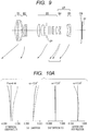
- FIG. 1 is a sectional view of a zoom lens on a wide angle end (short focal length end) according to the embodiment 1 of the present invention.
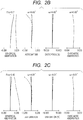
- FIGS. 2A , 2B, and 2C are aberration diagrams of the zoom lens at a wide angle end, a middle zooming position, and a telephoto end (long focal length end), respectively, according to the embodiment 1.
- the embodiment 1 illustrates the zoom lens with a zoom ratio of 3.45 and a numerical aperture of about 4.56 to 6.45.
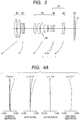
- FIG. 3 is a sectional view of a zoom lens on a wide angle end according to an embodiment 2 of the present invention.
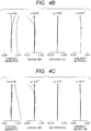
- FIGS. 4A , 4B, and 4C are aberration diagrams of the zoom lens at a wide angle end, a middle zooming position, and a telephoto end, respectively, according to the embodiment 2.
- the embodiment 2 illustrates the zoom lens with a zoom ratio of 3.45 and a numerical aperture of about 4.50 to 6.45.
- FIG. 5 is a sectional view of a zoom lens on a wide angle end according to an embodiment 3 of the present invention.
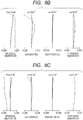
- FIGS. 6A , 6B, and 6C are aberration diagrams of the zoom lens at a wide angle end, a middle zooming position, and a telephoto end, respectively, according to the embodiment 3.
- the embodiment 3 illustrates the zoom lens with a zoom ratio of 3.45 and a numerical aperture of about 4.50 to 6.45.
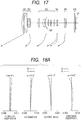
- FIG. 7 is a sectional view of a zoom lens on a wide angle end according to an embodiment 4 of the present invention.
- FIGS. 8A , 8B, and 8C are aberration diagrams of the zoom lens at a wide angle end, a middle zooming position, and a telephoto end, respectively, according to the embodiment 4.
- the embodiment 4 illustrates the zoom lens with a zoom ratio of 4.36 and a numerical aperture of about 4.50 to 6.45.
- FIG. 9 is a sectional view of a zoom lens on a wide angle end according to an embodiment 5 of the present invention.
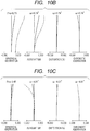
- FIGS. 10A , 10B, and 10C are aberration diagrams of the zoom lens at a wide angle end, a middle zooming position, and a telephoto end, respectively, according to the embodiment 5.
- the embodiment 5 illustrates the zoom lens with a zoom ratio of 3.45 and a numerical aperture of about 4.44 to 6.45.
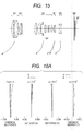
- FIG. 11 is a sectional view of a zoom lens on a wide angle end according to an embodiment 6 of the present invention.
- FIGS. 12A , 12B, and 12C are aberration diagrams of the zoom lens at a wide angle end, a middle zooming position, and a telephoto end, respectively, according to the embodiment 6.
- the embodiment 6 illustrates the zoom lens with a zoom ratio of 3.45 and a numerical aperture of about 4.50 to 6.45.
- FIG. 13 is a sectional view of a zoom lens on a wide angle end according an embodiment 7 of the present invention.
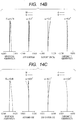
- FIGS. 14A , 14B, and 14C are aberration diagrams of the zoom lens at a wide angle end, a middle zooming position, and a telephoto end, respectively, according to the embodiment 7.
- the embodiment 7 illustrates the zoom lens with a zoom ratio of 3.45 and a numerical aperture of about 4.50 to 6.45.
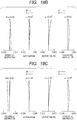
- FIG. 15 is a sectional view of a zoom lens on a wide angle end according to an embodiment 8 of the present invention.
- FIGS. 16A , 16B, and 16C are aberration diagrams of the zoom lens at a wide angle end, a middle zooming position, and a telephoto end, respectively, according to the embodiment 8.
- the embodiment 8 illustrates the zoom lens with a zoom ratio of 3.45 and a numerical aperture of about 4.50 to 6.45.
- FIG. 17 is a sectional view of a zoom lens on a wide angle end according to an embodiment 9 of the present invention.
- FIGS. 18A , 18B, and 18C are aberration diagrams of the zoom lens at a wide angle end, a middle zooming position, and a telephoto end, respectively, according to the embodiment 9.
- the embodiment 9 illustrates the zoom lens with a zoom ratio of 4.45 and a numerical aperture of about 4.50 to 6.45.
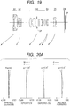
- FIG. 19 is a sectional view of a zoom lens on a wide angle end according to an embodiment 10 of the present invention.
- FIGS. 20A , 20B, and 20C are aberration diagrams of the zoom lens at a wide angle end, a middle zooming position, and a telephoto end, respectively, according to the embodiment 10.
- the embodiment 10 illustrates the zoom lens with a zoom ratio of 3.52 and a numerical aperture of about 4.50 to 6.45.
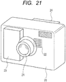
- FIG. 21 is a schematic view illustrating an essential part of a digital still camera (image pickup device) including the zoom lens according to the present invention.
- the zoom lens according to each embodiment is a photographing lens system used for an image pickup device such as a video camera, a digital still camera, a silver-halide film camera, or a TV camera.
- the left side is specified as an object side (front side)
- the right side is specified as an image side (rear side).
- supposing that i is the order of the lens unit from the object side indicates the ith lens unit.
- LR indicates the rear unit including one or more lens units.
- SP is an aperture diaphragm.
- GB is an optical block corresponding to an optical filter, a face plate, a low-pass filter, or an infrared cut filter.
- IP is an image plane.
- the image plane IP corresponds to an imaging plane of a solid-state image pickup device (photo-electric conversion element) such as a CCD sensor or a CMOS sensor, when the zoom lens is used as a photographing optical system of a video camera or a digital camera.
- the image plane IP corresponds to a film plane, when the zoom lens is used as a photographing optical system of a silver halide camera.
- Each arrow indicates a moving locus of each lens unit during the zooming (variable magnification) from the wide angle end to the telephoto end.
- a solid line indicates a d-line (wavelength: 587.6 nm)
- two-dot chain line indicates a g-line (wavelength: 435.8 nm).
- a solid line indicates a sagittal image plane on the d-line
- a dotted line indicates a meridional image plane on the d-line.
- a distortion aberration for the d-line is illustrated.
- a chromatic aberration in magnification for the g-line is illustrated.
- the wide angle end and the telephoto end mean a zooming position when the lens units for zooming are located on both ends of the range where they can move on the optical axis due to their mechanism.
- Each embodiment illustrates a zoom lens including, in the order from an object side to an image side, a first lens unit B1 having a positive refractive power, a second lens unit B2 having a negative refractive power, a third lens unit B3 having a positive refractive power, and a rear unit LR including two or more lens units.
- the rear unit LR includes, in the order from the object side to the image side, a fourth lens unit B4 having a negative refractive power and a fifth lens unit B5 having a positive or negative refractive power.
- An interval between the adjacent lens units is changed in order to carry out at least either one of zooming and focusing.
- the rear unit LR includes the fourth lens unit B4 having a negative refractive power and the fifth lens unit B5 having a negative refractive power in the embodiments 1, 3, 4, 5, 7, 8, and 9.
- the rear unit LR includes the fourth lens unit B4 having a negative refractive power and the fifth lens unit B5 having a positive refractive power.
- the rear unit LR may include three or more lens units by arranging one or more lens units on the image side of the fifth lens unit B5.
- each lens unit moves during the zooming from the wide angle end to the telephoto end, whereby satisfactory aberration correction is made within the entire zoom range.
- the first lens unit B1 to the third lens unit B3 move to the object side.
- the fourth lens unit B4 moves integral with the third lens unit B3 or the fifth lens unit B5.
- the fourth lens unit B4 moves integral with the third lens unit B3 or the fifth lens unit B5.
- the first, third, fourth, and fifth lens units move during the zooming from the wide angle end to the telephoto end, whereby satisfactory aberration correction is made within the entire zoom range.
- the second lens unit does not move.
- the fourth lens unit B4 moves integral with the third lens unit B3 or the fifth lens unit B5.
- the fourth lens unit B4 moves integral with the third lens unit B3 or the fifth lens unit B5.
- the fourth lens unit having a negative refractive power is moved toward the image plane during the focusing from infinity to close distance.
- the quick focusing can be facilitated by using the fourth lens unit that has relatively light weight as the focus lens unit.
- a broken arrow involved with the fourth lens unit B4 indicates a moving locus during the zooming when the fourth lens unit focuses on a subject in a close range.
- the fourth lens unit B4 and the fifth lens unit B5 are moved integral (with the same locus) during the zooming for the focus on infinity, whereby the mechanical mechanism is simplified, and the size of the whole zoom lens is reduced. Since the focus on an infinity point causes no focus shift, it is unnecessary to move only the focus lens unit, resulting in that the focus shift can be prevented, and the increase in the operating noise generated during the focusing operation can be reduced.
- the fourth lens unit B4 may move integral with the other lens units such as the third lens unit.
- the fourth lens unit B4 and the fifth lens unit B5 move integrally during the zooming for focusing on an object with the distance (the distance from the image plane) of 4 m.
- the fourth lens unit B4 may move integral with the third lens unit B3.
- the fourth lens unit B4 and the third lens unit B3 move integrally during the zooming for focusing on infinity.
- the fourth lens unit B4 may move integral with the other lens units such as the fifth lens unit.
- the fourth lens unit B4 and optional lens unit may move integrally during the zooming.
- the fourth lens unit B4 makes the focusing operation.
- the similar effect can be obtained even by performing the focusing operation by any lens unit, having the negative refractive power, closer to the image from the third lens unit B3. Therefore, the focus lens unit is not limited to the fourth lens unit B4.
- the zoom lens according to each of the embodiments 1 to 6 of the present invention includes the first, second, and third lens units B1 to B3 having respectively positive, negative, and positive refractive powers, and the rear unit LR including two or more lens units, in the order from the object side to the image side, in order to assure satisfactory zoom ratio with the compact size.
- the zoom lens also aims to have high optical performance and reduce the size of the whole zoom lens by arranging the negative focus lens unit on the rear unit LR and by appropriately setting the refractive power and the moving locus during the zooming of each lens unit.
- the zoom lens also reduces the size of the focus lens unit, and facilitates the high-speed focusing.
- a zoom lens including, in the order from the object side to the image side, lens units having respectively positive, negative, and positive refractive powers, and a rear unit having two or more lens units near the image side can easily provide high zoom ratio and high optical performance with a compact size.
- a zoom lens including, in the order from the object side to the image side, first lens unit to third lens unit having respectively positive, negative, and positive refractive powers, and a rear unit, having larger negative refractive power, on the side closer to the image than the third lens unit can shorten exit pupil distance, thereby being capable of reducing the length of the entire zoom lens.
- the third lens unit When the third lens unit is formed to have strong positive refractive power, on-axis flux emitted from the third lens unit is converged to reduce the height of the incident flux incident on the rear unit. The height of off-axis flux is also reduced. Therefore, the effective diameter of the rear unit becomes relatively small, and the focus lens unit can be downsized and lightweight by using the lens unit having the negative refractive power in the rear unit as the focus lens unit.
- the focus lens unit moves integral with the other lens units during the zooming for the specific object distance.
- This configuration can integrate the zooming operation mechanism to simplify the mechanical mechanism.
- This configuration in which the focus lens unit moves with the other lens units also prevents the focus shift and the generation of operating noise with the minimum focusing operation during the zooming for the specific object distance.
- the specific object distance by which the focus lens unit moves integral with the other lens units may be set to a long distance that is frequently used, if the zoom lens is a telephoto zoom lens, and may be set to a close distance, if the zoom lens is a wide angle zoom lens. If the specific object distance is set to a middle distance, the zoom lens can easily focus on both an object with a long distance and an object with a close distance. In this way, any specific object distances can be selected.
- the focus lens unit having a strong negative refractive power is arranged in order to downsize the whole zoom lens, much aberration occurs on the focus lens unit, so that the correction of various aberrations becomes difficult. Therefore, it is desirable to arrange a lens unit for correcting a field curvature and chromatic aberration in magnification on the side closer to the image from the focus lens unit. It is also desirable that the fourth lens unit B4 is the focus lens unit having a negative refractive power, and the fifth lens unit B5 having a positive or negative refractive power is arranged. The number of the lens units may be increased in order to realize higher performance.
- the exit pupil distance can optionally be changed to shorten the back focus, whereby the entire zoom lens can easily be downsized. It is preferable that at least three lens units including the first lens unit B1 move during the zooming. The movement of plural lens units including the first lens unit B1 can realize the reduction in size of the entire zoom lens and is easy to prevent the variation in various aberrations during the zooming.
- the effective diameter of the lens unit closest to the image plane is likely to increase.
- the effective diameter of the lens unit closest to the image plane needs to be made large in order to pass much off-axis flux.
- the lens unit arranged close to the image from the third lens unit and arranged in the last lens unit to be close to the object side, is specified as the focus lens unit.
- the lens unit can be divided based upon the change in the interval between the lens units on the optical axis during the zooming or the focusing, and the lens unit is defined to include not only a lens unit including plural lens units but also a lens unit including a single lens unit.
- the distance from the lens surface of the lens, closest to the object side, in the focus lens unit at a wide angle end to the image plane is defined as Lfsk.
- the distance from the lens surface of the lens, closest to the object side, in the focus lens unit on the wide angle end to the lens surface of the lens on the image side, closest to the image side, in the entire zoom lens is defined as Lf.
- a conditional expression of 1.4 ⁇ Lfsk / Lf ⁇ 4.0 is satisfied.
- the conditional expression (1) is involved with the arrangement of the focus lens unit in the optical axis direction.
- the focus lens unit becomes close to the third lens unit B3 over the upper limit of the conditional expression (1), the size of the focus lens unit can easily be reduced, but the distance from the focus lens unit to the image plane increases, which makes it difficult to reduce the size of the entire zoom lens.
- the focus lens unit becomes close to the image plane over the lower limit of the conditional expression (1), it becomes difficult to pass the off-axis flux unless the lens diameter increases for the focusing. Accordingly, the effective diameter and the weight of the focus lens unit increase, and this is not preferable.
- the focus lens unit moves integral with the lens unit other than the focus lens unit during the zooming on any focused length. Since the focus lens unit moves integral with the lens unit other than the focus lens unit, the zooming operation mechanism can be integrated, whereby the mechanical mechanism can be simplified. According to the configuration in which the focus lens unit moves integral with the other lens unit during the zooming, the focus shift during the zooming for an object with any distance can be prevented, and only a slight focusing operation is carried out to prevent the increase in operating noise.
- any focused length for an object during the zooming in which the focus lens unit moves integral with the other lens unit may be decided according to a specification.
- the focused length may be set according to an object with a long distance, this focused length being expected to be frequently used.
- the zoom lens is a wide angle zoom lens
- the focused length may be set according to an object with relatively a close distance. If the focused length is set according to an object with a middle distance, the zoom lens easily and quickly focuses on an object with a long distance and an object with a close distance.
- any focused length for an object may be selected. It is more preferable that a lens unit having a negative or positive refractive power is arranged on the image side of the focus lens unit.
- the focus lens unit having a strong negative refractive power is arranged in order to downsize the entire zoom lens, aberration greatly occurs on the focus lens unit. Therefore, it is desirable to arrange a lens unit for correcting a field curvature and chromatic aberration in magnification on the side closer to the image from the focus lens unit. It is also desirable that the fourth lens unit B4 is the focus lens unit having a negative refractive power, and the fifth lens unit B5 having a positive or negative refractive power is arranged on the side of the image plane. The number of the lens units may be increased in order to realize higher performance.
- each embodiment satisfies one or more conditional expressions described below.
- the focal length of the first lens unit B1 is defined as f1.
- the focal length of the second lens unit B2 is defined as f2.
- the focal length of the third lens unit B3 is defined as f3.
- the combined focal length of the rear unit on the wide angle end is defined as fn.
- the focal length of the focus lens unit is defined as ff.
- the combined focal length of the lens unit arranged closer to the image side than the focus lens unit on the wide angle end is defined as fi.
- the length of the zoom lens on the telephoto end is defined as Tl.
- the focal length of the zoom lens on the telephoto end is defined as ft.
- the focal length of the zoom lens on the wide angle end is defined as fw.
- the back focus on the wide angle end is defined as Wsk.
- the zoom lens preferably satisfies one or more conditional expressions described below.
- the conditional expression (2) specifies a ratio between the focal length (reciprocal of a refractive power) of the second lens unit B2 having a main zooming function and the combined focal length of the rear unit LR closer to the image side than the third lens unit B3 on the wide angle end.
- the combined refractive power (negative refractive power) of the rear unit LR becomes stronger such that the upper limit of the conditional expression (2) is exceeded, the size of the entire zoom lens is easily reduced, but the exit pupil distance becomes too short, so that image quality is liable to deteriorate.
- the negative refractive power of the second lens unit B2 becomes stronger such that the lower limit of the conditional expression (2) is exceeded, distortion aberration increases on the wide angle end, and the variation in the field curvature during the zooming increases. The correction of these aberrations is difficult.
- the conditional expression (3) specifies a ratio between the refractive power (reciprocal of a focal length) of the focus lens unit and the combined focal length of the lens unit closer to the image side than the focus lens unit on the wide angle end.
- the negative refractive power of the focus lens unit becomes weaker such that the lower limit of the conditional expression (3) is exceeded, the moving distance of the focus lens unit during the focusing increases, which makes it difficult to reduce the size of the entire zoom lens.
- the refractive power of the focus lens unit becomes stronger such that the upper limit of the conditional expression (3) is exceeded, the size of the entire zoom lens is easily reduced, since the moving distance of the focus lens unit during the focusing is decreased.
- the variation in various aberrations during the focusing increases.
- the conditional expression (4) specifies a ratio between the focal length of the first lens unit B1 and the combined focal length of the rear unit LR closer to the image side than the third lens unit B3 on the wide angle end.
- the conditional expression (5) specifies a ratio between the total length (the distance from the first lens surface to the image plane) of the zoom lens on the telephoto end and the focal length of the zoom lens on the telephoto end.
- the total length of the zoom lens becomes longer such that the upper limit of the conditional expression (5) is exceeded on the telephoto end, the reduction in size of the entire zoom lens becomes difficult.
- the total length of the zoom lens is shorter such that the lower limit of the conditional expression (5) on the telephoto end is exceeded, on-axis chromatic aberration and spherical aberration increase on the telephoto end, and these aberrations are difficult to be corrected. Therefore, many special materials having abnormal dispersion performance and aspherical lenses have to be used, and this is not preferable.
- conditional expression (6) specifies a ratio between the focal length of the second lens unit B2 having the main zooming function and the focal length of the entire zoom lens on the wide angle end.
- the conditional expression (7) specifies a ratio between the focal length of the focus lens unit and the back focus on the wide angle end.
- the refractive power of the focus lens unit becomes weaker such that the upper limit of the conditional expression (7) is exceeded, the moving distance of the focus lens unit during the focusing increases, so that it becomes difficult to reduce the size of the entire zoom lens.
- the back focus becomes longer such that the lower limit of the conditional expression (7) is exceeded, the reduction in size of the entire zoom lens becomes difficult.
- the conditional expression (8) specifies a ratio between the focal length of the focus lens unit and the focal length of the third lens unit B3.
- the refractive power of the third lens unit B3 becomes weaker such that the upper limit of the conditional expression (8) is exceeded, various aberrations are easy to be corrected, but it becomes difficult to reduce the size of the entire zoom lens, particularly the total length of the entire zoom lens.
- the refractive power of the third lens unit B3 becomes stronger such that the lower limit of the conditional expression (8) is exceeded, the spherical aberration and off-axis coma aberration are difficult to be corrected on the wide angle end.
- the conditional expression (9) specifies a ratio between the focal length of the second lens unit B2 having the main zooming function and the focal length of the entire zoom lens on the telephoto end.
- the refractive power of the second lens unit B2 becomes weaker such that the upper limit of the conditional expression (9) is exceeded, various aberrations are easy to be corrected, but it becomes difficult to reduce the size of the entire zoom lens, particularly the total length of the entire zoom lens.
- the refractive power of the second lens unit B2 becomes stronger such that the lower limit of the conditional expression (9) is exceeded, the field curvature and the chromatic aberration in magnification are difficult to be corrected on the wide angle end.
- the numerical ranges of the conditional expressions (1) to (9) are set as stated below.
- the numerical ranges of the conditional expressions (1a) to (9a) are set as stated below. 1.8 ⁇ Lfsk / Lf ⁇ 3.2 0.55 ⁇ f 2 / fn ⁇ 0.70 21 ⁇ fi / ff ⁇ 205 2.3 ⁇ f 1 / fn ⁇ 3.5 0.73 ⁇ Tl / ft ⁇ 0.76 0.35 ⁇ f 2 / fw ⁇ 0.50 1.30 ⁇ ff / Wsk ⁇ 1.95 0.6 ⁇ f 3 / fn ⁇ 1.1 0.08 ⁇ f 2 / ft ⁇ 0.13
- the zoom lens includes the fourth lens unit B4 having a negative refractive power and the fifth lens unit B5, wherein the fourth lens unit carries out the focusing.
- the fourth lens unit and the fifth lens unit move with the different locus.
- the difference in the moving amount is reduced by setting appropriate power, whereby the moving mechanism can be simplified, and the entire zoom lens can easily be reduced in size, as in the embodiments 1 to 6.
- a zoom lens including, in the order from the object side to the image side, lens units having respectively positive, negative, positive and negative refractive powers, and a rear unit having one or more lens units near the image side can easily provide high zoom ratio and high optical performance with a compact size.
- a zoom lens including, in the order from the object side to the image side, first lens unit to third lens unit having respectively positive, negative, and positive refractive powers, and a rear unit, having stronger negative refractive power, on the side closer to the image than the third lens unit can shorten exit pupil distance, thereby being capable of reducing the length of the entire zoom lens.
- the lens unit, having the negative refractive power, in the rear unit on the image side of the third lens unit is specified as the focus lens unit.
- the size and the weight of the focus lens unit can be reduced.
- the effective diameter of the lens unit closest to the image plane is likely to increase. The reason of this is as follows. Specifically, when the image pickup element and the last lens unit become close to each other due to the reduction in size of the entire zoom lens, the effective diameter of the lens unit closest to the image plane needs to be made large in order to pass much off-axis flux.
- the fourth lens unit is used as the focus lens unit.
- a double telephoto-type structure can be made by forming the fourth lens unit to have the negative refractive power. This configuration brings an effect in which a short optical system is easy to be realized.
- the fourth lens unit used for the focusing has the strong refractive power in order to reduce the moving amount during the focusing as much as possible. This is because, the smaller the moving amount is, the more the driving mechanism can be reduced.
- the fifth lens unit having a negative or positive refractive power is arranged on the side of the image plane to correct the field curvature and the chromatic aberration in magnification.
- the zoom lens in each embodiment is characterized by simultaneously satisfying the conditional expressions of: 0.55 ⁇ f 2 / f 4 ⁇ 0.8 0.6 ⁇ Tl / ft ⁇ 0.8 when the focal length of the second lens unit is defined as f2, the focal length of the fourth lens unit is defined as f4, the focal length of the zoom lens on the telephoto end is defined as ft, and the length of the entire zoom lens on the telephoto end is defined as Tl.
- the conditional expression (10) specifies a ratio between the focal length of the second lens unit B2 having the main zooming function and the focal length of the fourth lens unit B4 that carries out the focusing operation.
- the refractive power of the fourth lens unit becomes stronger such that the upper limit of the conditional expression (10) is exceeded, the moving amount during the focusing can be reduced, but the variation in the field curvature and the chromatic aberration in magnification caused by the focusing increases, thereby the correction is difficult.
- the refractive power of the fourth lens unit becomes weaker such that the lower limit of the conditional expression (10) is exceeded, the variation in various aberrations during the focusing can easily be prevented, but the moving amount during the focusing increases. This is not preferable for the reduction in size of the zoom lens.
- this zoom lens When a zoom lens simultaneously satisfies the conditional expression (10) and the conditional expression (5), this zoom lens can be downsized and have a high optical performance.
- each embodiment satisfies one or more conditional expressions described below together with the conditional expressions (10) and (5).
- the focal length of the first lens unit B1 is defined as f1.
- the focal length of the second lens unit B2 is defined as f2.
- the focal length of the fourth lens unit B4 is defined as f4.
- the focal length of the entire zoom lens on the telephoto end is defined as ft.
- the zoom lens preferably satisfies one or more conditional expressions described below.
- the conditional expression (11) specifies a ratio between the focal length of the first lens unit B1 and the focal length of the entire zoom lens on the telephoto end.
- the focal length f1 of the first lens unit B1 becomes smaller such that the upper limit of the conditional expression (11) is exceeded, the spherical aberration and the on-axis chromatic aberration are difficult to be corrected.
- the focal length of the first lens unit B1 becomes larger such that the lower limit of the conditional expression (11) is exceeded, the refraction by the first lens unit is reduced, and the diameter of the lens has to be increased. This is not preferable for reducing the size of the entire zoom lens.
- the conditional expression (12) specifies a ratio between the focal length of the second lens unit B2 having the largest refractive power in the entire zoom lens and the focal length of the entire zoom lens on the telephoto end.
- the focal length f2 of the second lens unit B2 becomes smaller such that the upper limit of the conditional expression (12) is exceeded, the zooming function becomes strong. Therefore, high zoom can be attained with the small moving amount, and this is preferable for reducing the size.
- the moving amount of the second lens unit or the other lens units has to be increased in order to assure the desired zooming. This is not preferable for the reduction in size.
- the conditional expression (13) specifies a ratio between the focal length of the fourth lens unit B4 performing the focusing operation and the focal length of the entire zoom lens on the telephoto end.
- the focal length f4 of the fourth lens unit B4 becomes smaller such that the upper limit of the conditional expression (13) is exceeded, the focusing can be realized with a small moving amount, and this is preferable for the reduction in size of a system including a driving unit and for preventing noise.
- the conditional expression (14) specifies a ratio between the focal length of the first lens unit B1 and the focal length of the fourth lens unit B4.
- the focal length f4 of the fourth lens unit B4 becomes smaller such that the upper limit of the conditional expression (14) is exceeded, the focusing operation can be realized with a small moving amount, and this is preferable for the reduction in size of a system including a driving unit and for preventing noise.
- the numerical ranges of the conditional expressions (11) to (14) are set as stated below. 1.5 ⁇ ft / f 1 ⁇ 2.8 6.5 ⁇ ft / f 2 ⁇ 11.5 5.3 ⁇ ft / f 4 ⁇ 7.3 2.0 ⁇ f 1 / f 4 ⁇ 3.5
- the numerical ranges of the conditional expressions (11a) to (14a) are set as stated below. 1.8 ⁇ ft / f 1 ⁇ 2.2 7.0 ⁇ ft / f 2 ⁇ 11.0 5.5 ⁇ ft / f 4 ⁇ 7.0 2.5 ⁇ f 1 / f 4 ⁇ 3.3
- each embodiment can provide a compact zoom lens having high optical performance and high zoom ratio, wherein a size and weight of a focus lens unit can be reduced. Therefore, each embodiment easily realizes an image pickup device including a quiet and quick focusing function with reduced size including a mechanical mechanism.
- FIG. 21 illustrates a digital camera body 20 and a photographing optical system 21 including the zoom lens according to the embodiments described above.
- the digital camera includes an image pickup element (photo-electric conversion element) 22, such as a CCD, receiving a subject image (image) by the photographing optical system 21, and a recording unit 23 that records the subject image received by the image pickup element 22.
- the digital camera also includes a viewfinder 24 by which a user observes the subject image displayed onto a display device not illustrated.
- the display device is composed of a liquid crystal panel, and displays the subject image formed on the image pickup element 22.
- the application of the zoom lens according to the present invention to an image pickup device such as a digital camera realizes a compact image pickup device having high optical performance.
- i indicates the number of the surface counted from the object side.
- ri indicates a curvature radius of the ith optical surface (the ith surface).
- di indicates an interval between the ith surface and the (i + 1)th surface on the axis.
- ndi and vdi respectively indicate a refractive index and Abbe number of the material of the ith optical member relative to the d-line. Two surfaces closest to the image correspond to a glass block G.
- * means a plane having an aspherical shape.
- "e - x" means 10 -x .
- BF indicates a back focus, and this is represented by the distance from the surface of the last lens to the image plane in terms of air.
- a wide angle means the wide angle end
- a middle means the middle zooming position
- a telephoto means the telephoto end.
- Table 1 represents the relationship between each conditional expression and each numerical example.
Description
- The present invention relates to a zoom lens, and an image pickup device provided with the same, and is well adaptable to an image pickup device using a solid-state image pickup element, such as a video camera, an electronic still camera, a broadcast camera, or a monitoring camera, or to an image pickup device such as a camera using a silver halide film.
- A photographing optical system in an image pickup device has been demanded which uses a high-performance zoom lens having a high zoom ratio and which enables a reduction in the size of the system. An image pickup device has also been demanded which has an autofocus (automatic focus detection) mechanism and which is capable of photographing not only a still image but also a moving image. When operating noise from the autofocus mechanism is loud during the photographing of a moving image, an image pickup device having the autofocus mechanism might record the operating noise with the moving image. Therefore, an image pickup device having an autofocus mechanism has been demanded which is capable of performing quiet and quick focusing.
-
U.S. Patent. No. 8,331,035 describes a 4-unit zoom lens including four lens units having respectively a positive refractive power, a negative refractive power, a positive refractive power, and a negative refractive power in the order from an object side to an image side, wherein focusing is carried out by using the fourth lens unit to satisfactorily photograph a still image and a moving image.U.S. Patent. No. 8,451,549 and Japanese Patent Application Laid-Open No.2000-180722 US 2009/207501 A1 . - A zoom lens used in an image pickup device is required to be compact (downsized) as a whole, to have a high zoom ratio (high magnification ratio), and to have high optical performance within the entire zoom range. In most zoom lenses, a focus lens unit is moved in synchronization with zooming in order to prevent a focus variation during the zooming. When the focus lens unit and other lens units are controlled by different driving units, it becomes difficult to move the focus lens unit completely in synchronization with the zooming due to an electrical control delay or speed limit of motors, for example, whereby defocusing occurs upon the zooming.
- In this case, the defocusing upon the zooming can be reduced by quickly operating the focus lens unit. However, this operation increases the operating noise. Therefore, use of a focusing system and zooming system capable of easily preventing the defocusing upon the zooming is required. When a lens unit moving with the zooming is used as a focus lens unit, the focus lens unit has to be provided with two types of moving mechanisms, which are a moving mechanism for zooming and a moving mechanism for focusing. It is also necessary to move the focus lens unit very fast.
- When the focus lens unit is provided with two types of moving mechanisms, the whole system becomes large in size, and operating noise during focusing increases. Accordingly, a zoom lens used in an image pickup device has to have a focusing mechanism that can easily perform quiet and quick focusing and that can easily prevent defocusing during zooming. In particular, since the operating noise during focusing is mainly determined by the weight of a focus lens unit, it is important to appropriately set an arrangement, size, and weight of the focus lens unit in an optical path.
- According to the present invention there is provided a zoom lens as claimed in
claim 1. - Further features of the present invention will become apparent from the following description of embodiments with reference to the attached drawings. Each of the embodiments of the present invention described below can be implemented solely or as a combination of a plurality of the embodiments or features thereof where necessary or where the combination of elements or features from individual embodiments in a single embodiment is beneficial.
-
-
FIG. 1 is a sectional view of a lens according to anembodiment 1 of the present invention. -
Fig. 2A is an aberration diagram of the lens on a wide angle end according to theembodiment 1 of the present invention. -
FIG. 2B is an aberration diagram of the lens on a middle zooming position according to theembodiment 1 of the present invention. -
FIG. 2C is an aberration diagram of the lens on a telephoto end according to theembodiment 1 of the present invention. -
FIG. 3 is a sectional view of a lens according to an embodiment 2 of the present invention. -
FIG. 4A is an aberration diagram of the lens on a wide angle end according to the embodiment 2 of the present invention. -
FIG. 4B is an aberration diagram of the lens on a middle zooming position according to the embodiment 2 of the present invention. -
FIG. 4C is an aberration diagram of the lens on a telephoto end according to the embodiment 2 of the present invention. -
FIG. 5 is a sectional view of a lens according to an embodiment 3 of the present invention. -
FIG. 6A is an aberration diagram of the lens on a wide angle end according to the embodiment 3 of the present invention. -
FIG. 6B is an aberration diagram of the lens on a middle zooming position according to the embodiment 3 of the present invention. -
FIG. 6C is an aberration diagram of the lens on a telephoto end according to the embodiment 3 of the present invention. -
FIG. 7 is a sectional view of a lens according to an embodiment 4 of the present invention. -
FIG. 8A is an aberration diagram of the lens on a wide angle end according to the embodiment 4 of the present invention. -
FIG. 8B is an aberration diagram of the lens on a middle zooming position according to the embodiment 4 of the present invention. -
FIG. 8C is an aberration diagram of the lens on a telephoto end according to the embodiment 4 of the present invention. -
FIG. 9 is a sectional view of a lens according to an embodiment 5 of the present invention. -
FIG. 10A is an aberration diagram of the lens on a wide angle end according to the embodiment 5 of the present invention. -
FIG. 10B is an aberration diagram of the lens on a middle zooming position according to the embodiment 5 of the present invention. -
FIG. 10C is an aberration diagram of the lens on a telephoto end according to the embodiment 5 of the present invention. -
FIG. 11 is a sectional view of a lens according to an embodiment 6 of the present invention. -
FIG. 12A is an aberration diagram of the lens on a wide angle end according to the embodiment 6 of the present invention. -
FIG. 12B is an aberration diagram of the lens on a middle zooming position according to the embodiment 6 of the present invention. -
FIG. 12C is an aberration diagram of the lens on a telephoto end according to the embodiment 6 of the present invention. -
FIG. 13 is a sectional view of a lens according to an embodiment 7 of the present invention. -
FIG. 14A is an aberration diagram of the lens on a wide angle end according to the embodiment 7 of the present invention. -
FIG. 14B is an aberration diagram of the lens on a middle zooming position according to the embodiment 7 of the present invention. -
FIG. 14C is an aberration diagram of the lens on a telephoto end according to the embodiment 7 of the present invention. -
FIG. 15 is a sectional view of a lens according to an embodiment 8 of the present invention. -
FIG. 16A is an aberration diagram of the lens on a wide angle end according to the embodiment 8 of the present invention. -
FIG. 16B is an aberration diagram of the lens on a middle zooming position according to the embodiment 8 of the present invention. -
FIG. 16C is an aberration diagram of the lens on a telephoto end according to the embodiment 8 of the present invention. -
FIG. 17 is a sectional view of a lens according to an embodiment 9 of the present invention. -
FIG. 18A is an aberration diagram of the lens on a wide angle end according to the embodiment 9 of the present invention. -
FIG. 18B is an aberration diagram of the lens on a middle zooming position according to the embodiment 9 of the present invention. -
FIG. 18C is an aberration diagram of the lens on a telephoto end according to the embodiment 9 of the present invention. -
FIG. 19 is a sectional view of a lens according to an embodiment 10 of the present invention. -
FIG. 20A is an aberration diagram of the lens on a wide angle end according to the embodiment 10 of the present invention. -
FIG. 20B is an aberration diagram of the lens on a middle zooming position according to the embodiment 10 of the present invention. -
FIG. 20C is an aberration diagram of the lens on a telephoto end according to the embodiment 10 of the present invention. -
FIG. 21 is a schematic view illustrating an essential part of an image pickup device according to the present invention. - Preferred embodiments of the present invention will now be described in detail in accordance with the accompanying drawings. A zoom lens according to each of embodiments of the present invention includes, in the order from an object side to an image side, a first lens unit having a positive refractive power (optical power = reciprocal of a focal length), a second lens unit having a negative refractive power, a third lens unit having a positive refractive power, and a rear unit including two or more lens units. An interval between the adjacent lens units is changed in order to carry out at least either one of zooming and focusing. The rear unit includes a focus lens unit that moves during the focusing. The focus lens unit moves integral with the other lens units during the zooming for focusing on a specified object distance.
-
FIG. 1 is a sectional view of a zoom lens on a wide angle end (short focal length end) according to theembodiment 1 of the present invention.FIGS. 2A ,2B, and 2C are aberration diagrams of the zoom lens at a wide angle end, a middle zooming position, and a telephoto end (long focal length end), respectively, according to theembodiment 1. Theembodiment 1 illustrates the zoom lens with a zoom ratio of 3.45 and a numerical aperture of about 4.56 to 6.45. -
FIG. 3 is a sectional view of a zoom lens on a wide angle end according to an embodiment 2 of the present invention.FIGS. 4A ,4B, and 4C are aberration diagrams of the zoom lens at a wide angle end, a middle zooming position, and a telephoto end, respectively, according to the embodiment 2. The embodiment 2 illustrates the zoom lens with a zoom ratio of 3.45 and a numerical aperture of about 4.50 to 6.45. -
FIG. 5 is a sectional view of a zoom lens on a wide angle end according to an embodiment 3 of the present invention.FIGS. 6A ,6B, and 6C are aberration diagrams of the zoom lens at a wide angle end, a middle zooming position, and a telephoto end, respectively, according to the embodiment 3. The embodiment 3 illustrates the zoom lens with a zoom ratio of 3.45 and a numerical aperture of about 4.50 to 6.45. -
FIG. 7 is a sectional view of a zoom lens on a wide angle end according to an embodiment 4 of the present invention.FIGS. 8A ,8B, and 8C are aberration diagrams of the zoom lens at a wide angle end, a middle zooming position, and a telephoto end, respectively, according to the embodiment 4. The embodiment 4 illustrates the zoom lens with a zoom ratio of 4.36 and a numerical aperture of about 4.50 to 6.45. -
FIG. 9 is a sectional view of a zoom lens on a wide angle end according to an embodiment 5 of the present invention.FIGS. 10A ,10B, and 10C are aberration diagrams of the zoom lens at a wide angle end, a middle zooming position, and a telephoto end, respectively, according to the embodiment 5. The embodiment 5 illustrates the zoom lens with a zoom ratio of 3.45 and a numerical aperture of about 4.44 to 6.45. -
FIG. 11 is a sectional view of a zoom lens on a wide angle end according to an embodiment 6 of the present invention.FIGS. 12A ,12B, and 12C are aberration diagrams of the zoom lens at a wide angle end, a middle zooming position, and a telephoto end, respectively, according to the embodiment 6. The embodiment 6 illustrates the zoom lens with a zoom ratio of 3.45 and a numerical aperture of about 4.50 to 6.45. -
FIG. 13 is a sectional view of a zoom lens on a wide angle end according an embodiment 7 of the present invention.FIGS. 14A ,14B, and 14C are aberration diagrams of the zoom lens at a wide angle end, a middle zooming position, and a telephoto end, respectively, according to the embodiment 7. The embodiment 7 illustrates the zoom lens with a zoom ratio of 3.45 and a numerical aperture of about 4.50 to 6.45. -
FIG. 15 is a sectional view of a zoom lens on a wide angle end according to an embodiment 8 of the present invention.FIGS. 16A ,16B, and 16C are aberration diagrams of the zoom lens at a wide angle end, a middle zooming position, and a telephoto end, respectively, according to the embodiment 8. The embodiment 8 illustrates the zoom lens with a zoom ratio of 3.45 and a numerical aperture of about 4.50 to 6.45. -
FIG. 17 is a sectional view of a zoom lens on a wide angle end according to an embodiment 9 of the present invention.FIGS. 18A ,18B, and 18C are aberration diagrams of the zoom lens at a wide angle end, a middle zooming position, and a telephoto end, respectively, according to the embodiment 9. The embodiment 9 illustrates the zoom lens with a zoom ratio of 4.45 and a numerical aperture of about 4.50 to 6.45. -
FIG. 19 is a sectional view of a zoom lens on a wide angle end according to an embodiment 10 of the present invention.FIGS. 20A ,20B, and 20C are aberration diagrams of the zoom lens at a wide angle end, a middle zooming position, and a telephoto end, respectively, according to the embodiment 10. The embodiment 10 illustrates the zoom lens with a zoom ratio of 3.52 and a numerical aperture of about 4.50 to 6.45. -
FIG. 21 is a schematic view illustrating an essential part of a digital still camera (image pickup device) including the zoom lens according to the present invention. - The zoom lens according to each embodiment is a photographing lens system used for an image pickup device such as a video camera, a digital still camera, a silver-halide film camera, or a TV camera. In the sectional views of the lens, the left side is specified as an object side (front side), and the right side is specified as an image side (rear side). In the sectional views of the lens, supposing that i is the order of the lens unit from the object side, Bi indicates the ith lens unit. LR indicates the rear unit including one or more lens units.
- SP is an aperture diaphragm. GB is an optical block corresponding to an optical filter, a face plate, a low-pass filter, or an infrared cut filter. IP is an image plane. The image plane IP corresponds to an imaging plane of a solid-state image pickup device (photo-electric conversion element) such as a CCD sensor or a CMOS sensor, when the zoom lens is used as a photographing optical system of a video camera or a digital camera. The image plane IP corresponds to a film plane, when the zoom lens is used as a photographing optical system of a silver halide camera.
- Each arrow indicates a moving locus of each lens unit during the zooming (variable magnification) from the wide angle end to the telephoto end. In spherical aberration diagrams, a solid line indicates a d-line (wavelength: 587.6 nm), and two-dot chain line indicates a g-line (wavelength: 435.8 nm). In astigmatism diagrams, a solid line indicates a sagittal image plane on the d-line, and a dotted line indicates a meridional image plane on the d-line. A distortion aberration for the d-line is illustrated. A chromatic aberration in magnification for the g-line is illustrated. In each embodiment described below, the wide angle end and the telephoto end mean a zooming position when the lens units for zooming are located on both ends of the range where they can move on the optical axis due to their mechanism.
- Each embodiment illustrates a zoom lens including, in the order from an object side to an image side, a first lens unit B1 having a positive refractive power, a second lens unit B2 having a negative refractive power, a third lens unit B3 having a positive refractive power, and a rear unit LR including two or more lens units. The rear unit LR includes, in the order from the object side to the image side, a fourth lens unit B4 having a negative refractive power and a fifth lens unit B5 having a positive or negative refractive power. An interval between the adjacent lens units is changed in order to carry out at least either one of zooming and focusing.
- The rear unit LR includes the fourth lens unit B4 having a negative refractive power and the fifth lens unit B5 having a negative refractive power in the
embodiments 1, 3, 4, 5, 7, 8, and 9. In the embodiments 2, 6, and 10, the rear unit LR includes the fourth lens unit B4 having a negative refractive power and the fifth lens unit B5 having a positive refractive power. In each embodiment, the rear unit LR may include three or more lens units by arranging one or more lens units on the image side of the fifth lens unit B5. - In
embodiments 1 to 7, 9, and 10, each lens unit moves during the zooming from the wide angle end to the telephoto end, whereby satisfactory aberration correction is made within the entire zoom range. During the zooming from the wide angle end to the telephoto end, the first lens unit B1 to the third lens unit B3 move to the object side. During the zooming for focusing on infinity, the fourth lens unit B4 moves integral with the third lens unit B3 or the fifth lens unit B5. During the zooming for focusing on finite distance, the fourth lens unit B4 moves integral with the third lens unit B3 or the fifth lens unit B5. - In the embodiment 8, the first, third, fourth, and fifth lens units move during the zooming from the wide angle end to the telephoto end, whereby satisfactory aberration correction is made within the entire zoom range. During the zooming from the wide angle end to the telephoto end, the second lens unit does not move. During the zooming for focusing on infinity, the fourth lens unit B4 moves integral with the third lens unit B3 or the fifth lens unit B5. During the zooming for focusing on finite distance, the fourth lens unit B4 moves integral with the third lens unit B3 or the fifth lens unit B5.
- In each embodiment, the fourth lens unit having a negative refractive power is moved toward the image plane during the focusing from infinity to close distance. The quick focusing can be facilitated by using the fourth lens unit that has relatively light weight as the focus lens unit. A broken arrow involved with the fourth lens unit B4 indicates a moving locus during the zooming when the fourth lens unit focuses on a subject in a close range.
- In the
embodiments 1, and 4 to 6, the fourth lens unit B4 and the fifth lens unit B5 are moved integral (with the same locus) during the zooming for the focus on infinity, whereby the mechanical mechanism is simplified, and the size of the whole zoom lens is reduced. Since the focus on an infinity point causes no focus shift, it is unnecessary to move only the focus lens unit, resulting in that the focus shift can be prevented, and the increase in the operating noise generated during the focusing operation can be reduced. The fourth lens unit B4 may move integral with the other lens units such as the third lens unit. - In the embodiment 2, the fourth lens unit B4 and the fifth lens unit B5 move integrally during the zooming for focusing on an object with the distance (the distance from the image plane) of 4 m. The fourth lens unit B4 may move integral with the third lens unit B3.
- In the embodiment 3, the fourth lens unit B4 and the third lens unit B3 move integrally during the zooming for focusing on infinity. The fourth lens unit B4 may move integral with the other lens units such as the fifth lens unit.
- In the
embodiments 1 to 6, the fourth lens unit B4 and optional lens unit may move integrally during the zooming. In theembodiments 1 to 6, the fourth lens unit B4 makes the focusing operation. However, the similar effect can be obtained even by performing the focusing operation by any lens unit, having the negative refractive power, closer to the image from the third lens unit B3. Therefore, the focus lens unit is not limited to the fourth lens unit B4. - The zoom lens according to each of the
embodiments 1 to 6 of the present invention includes the first, second, and third lens units B1 to B3 having respectively positive, negative, and positive refractive powers, and the rear unit LR including two or more lens units, in the order from the object side to the image side, in order to assure satisfactory zoom ratio with the compact size. The zoom lens also aims to have high optical performance and reduce the size of the whole zoom lens by arranging the negative focus lens unit on the rear unit LR and by appropriately setting the refractive power and the moving locus during the zooming of each lens unit. The zoom lens also reduces the size of the focus lens unit, and facilitates the high-speed focusing. - In general, a zoom lens including, in the order from the object side to the image side, lens units having respectively positive, negative, and positive refractive powers, and a rear unit having two or more lens units near the image side can easily provide high zoom ratio and high optical performance with a compact size. In particular, a zoom lens including, in the order from the object side to the image side, first lens unit to third lens unit having respectively positive, negative, and positive refractive powers, and a rear unit, having larger negative refractive power, on the side closer to the image than the third lens unit can shorten exit pupil distance, thereby being capable of reducing the length of the entire zoom lens.
- When the third lens unit is formed to have strong positive refractive power, on-axis flux emitted from the third lens unit is converged to reduce the height of the incident flux incident on the rear unit. The height of off-axis flux is also reduced. Therefore, the effective diameter of the rear unit becomes relatively small, and the focus lens unit can be downsized and lightweight by using the lens unit having the negative refractive power in the rear unit as the focus lens unit.
- In the
embodiments 1 to 6, the focus lens unit moves integral with the other lens units during the zooming for the specific object distance. This configuration can integrate the zooming operation mechanism to simplify the mechanical mechanism. This configuration in which the focus lens unit moves with the other lens units also prevents the focus shift and the generation of operating noise with the minimum focusing operation during the zooming for the specific object distance. - The specific object distance by which the focus lens unit moves integral with the other lens units may be set to a long distance that is frequently used, if the zoom lens is a telephoto zoom lens, and may be set to a close distance, if the zoom lens is a wide angle zoom lens. If the specific object distance is set to a middle distance, the zoom lens can easily focus on both an object with a long distance and an object with a close distance. In this way, any specific object distances can be selected.
- When the focus lens unit having a strong negative refractive power is arranged in order to downsize the whole zoom lens, much aberration occurs on the focus lens unit, so that the correction of various aberrations becomes difficult. Therefore, it is desirable to arrange a lens unit for correcting a field curvature and chromatic aberration in magnification on the side closer to the image from the focus lens unit. It is also desirable that the fourth lens unit B4 is the focus lens unit having a negative refractive power, and the fifth lens unit B5 having a positive or negative refractive power is arranged. The number of the lens units may be increased in order to realize higher performance.
- When the lens unit having a negative refractive power is arranged on the image side of the focus lens unit to set the combined focal length of the rear unit LR closer to the image side than the third lens unit B3 to have a negative refractive power, the exit pupil distance can optionally be changed to shorten the back focus, whereby the entire zoom lens can easily be downsized. It is preferable that at least three lens units including the first lens unit B1 move during the zooming. The movement of plural lens units including the first lens unit B1 can realize the reduction in size of the entire zoom lens and is easy to prevent the variation in various aberrations during the zooming.
- On the other hand, when the entire zoom lens is downsized to reduce the back focus, the effective diameter of the lens unit closest to the image plane is likely to increase. The reason of this is as follows. Specifically, when the image pickup element and the last lens unit become close to each other due to the reduction in size of the entire zoom lens, the effective diameter of the lens unit closest to the image plane needs to be made large in order to pass much off-axis flux.
- In view of this, in each embodiment, the lens unit, arranged close to the image from the third lens unit and arranged in the last lens unit to be close to the object side, is specified as the focus lens unit. The lens unit can be divided based upon the change in the interval between the lens units on the optical axis during the zooming or the focusing, and the lens unit is defined to include not only a lens unit including plural lens units but also a lens unit including a single lens unit.
- In each embodiment, the distance from the lens surface of the lens, closest to the object side, in the focus lens unit at a wide angle end to the image plane is defined as Lfsk. The distance from the lens surface of the lens, closest to the object side, in the focus lens unit on the wide angle end to the lens surface of the lens on the image side, closest to the image side, in the entire zoom lens is defined as Lf. In this case, a conditional expression of

- The conditional expression (1) is involved with the arrangement of the focus lens unit in the optical axis direction. When the focus lens unit becomes close to the third lens unit B3 over the upper limit of the conditional expression (1), the size of the focus lens unit can easily be reduced, but the distance from the focus lens unit to the image plane increases, which makes it difficult to reduce the size of the entire zoom lens. When the focus lens unit becomes close to the image plane over the lower limit of the conditional expression (1), it becomes difficult to pass the off-axis flux unless the lens diameter increases for the focusing. Accordingly, the effective diameter and the weight of the focus lens unit increase, and this is not preferable.
- In the
embodiments 1 to 6, the focus lens unit moves integral with the lens unit other than the focus lens unit during the zooming on any focused length. Since the focus lens unit moves integral with the lens unit other than the focus lens unit, the zooming operation mechanism can be integrated, whereby the mechanical mechanism can be simplified. According to the configuration in which the focus lens unit moves integral with the other lens unit during the zooming, the focus shift during the zooming for an object with any distance can be prevented, and only a slight focusing operation is carried out to prevent the increase in operating noise. - Any focused length for an object during the zooming in which the focus lens unit moves integral with the other lens unit may be decided according to a specification. For example, when the zoom lens is a telephoto zoom lens, the focused length may be set according to an object with a long distance, this focused length being expected to be frequently used. When the zoom lens is a wide angle zoom lens, the focused length may be set according to an object with relatively a close distance. If the focused length is set according to an object with a middle distance, the zoom lens easily and quickly focuses on an object with a long distance and an object with a close distance. As described above, any focused length for an object may be selected. It is more preferable that a lens unit having a negative or positive refractive power is arranged on the image side of the focus lens unit.
- When the focus lens unit having a strong negative refractive power is arranged in order to downsize the entire zoom lens, aberration greatly occurs on the focus lens unit. Therefore, it is desirable to arrange a lens unit for correcting a field curvature and chromatic aberration in magnification on the side closer to the image from the focus lens unit. It is also desirable that the fourth lens unit B4 is the focus lens unit having a negative refractive power, and the fifth lens unit B5 having a positive or negative refractive power is arranged on the side of the image plane. The number of the lens units may be increased in order to realize higher performance.
- In each embodiment, five lens units move during the zooming. The variation in the chromatic aberration during the focusing is reduced by arranging at least one positive lens and one negative lens in the focus lens unit. Preferably, each embodiment satisfies one or more conditional expressions described below. The focal length of the first lens unit B1 is defined as f1. The focal length of the second lens unit B2 is defined as f2. The focal length of the third lens unit B3 is defined as f3. The combined focal length of the rear unit on the wide angle end is defined as fn. The focal length of the focus lens unit is defined as ff. The combined focal length of the lens unit arranged closer to the image side than the focus lens unit on the wide angle end is defined as fi.
- The length of the zoom lens on the telephoto end is defined as Tl. The focal length of the zoom lens on the telephoto end is defined as ft. The focal length of the zoom lens on the wide angle end is defined as fw. The back focus on the wide angle end is defined as Wsk. In this case, the zoom lens preferably satisfies one or more conditional expressions described below.


- The technical meaning of each conditional expression described above will be described.
- The conditional expression (2) specifies a ratio between the focal length (reciprocal of a refractive power) of the second lens unit B2 having a main zooming function and the combined focal length of the rear unit LR closer to the image side than the third lens unit B3 on the wide angle end. When the combined refractive power (negative refractive power) of the rear unit LR becomes stronger such that the upper limit of the conditional expression (2) is exceeded, the size of the entire zoom lens is easily reduced, but the exit pupil distance becomes too short, so that image quality is liable to deteriorate. When the negative refractive power of the second lens unit B2 becomes stronger such that the lower limit of the conditional expression (2) is exceeded, distortion aberration increases on the wide angle end, and the variation in the field curvature during the zooming increases. The correction of these aberrations is difficult.
- The conditional expression (3) specifies a ratio between the refractive power (reciprocal of a focal length) of the focus lens unit and the combined focal length of the lens unit closer to the image side than the focus lens unit on the wide angle end. When the negative refractive power of the focus lens unit becomes weaker such that the lower limit of the conditional expression (3) is exceeded, the moving distance of the focus lens unit during the focusing increases, which makes it difficult to reduce the size of the entire zoom lens. When the refractive power of the focus lens unit becomes stronger such that the upper limit of the conditional expression (3) is exceeded, the size of the entire zoom lens is easily reduced, since the moving distance of the focus lens unit during the focusing is decreased. However, the variation in various aberrations during the focusing increases.
- The conditional expression (4) specifies a ratio between the focal length of the first lens unit B1 and the combined focal length of the rear unit LR closer to the image side than the third lens unit B3 on the wide angle end. When the refractive power of the first lens unit B1 becomes weaker such that the upper limit of the conditional expression (4) is exceeded, a predetermined zoom ratio cannot be obtained, unless the moving amount of the first lens unit B1 increases during the zooming. Therefore, the reduction in size of the entire zoom lens becomes difficult. When the refractive power of the first lens unit B1 becomes stronger such that the lower limit of the conditional expression (4) is exceeded, the moving amount of the first lens unit B1 during the zooming can be decreased, so that the size of the entire zoom lens can easily be reduced. However, on-axis chromatic aberration on the telephoto end increases, and this aberration is difficult to be corrected.
- The conditional expression (5) specifies a ratio between the total length (the distance from the first lens surface to the image plane) of the zoom lens on the telephoto end and the focal length of the zoom lens on the telephoto end. When the total length of the zoom lens becomes longer such that the upper limit of the conditional expression (5) is exceeded on the telephoto end, the reduction in size of the entire zoom lens becomes difficult. When the total length of the zoom lens is shorter such that the lower limit of the conditional expression (5) on the telephoto end is exceeded, on-axis chromatic aberration and spherical aberration increase on the telephoto end, and these aberrations are difficult to be corrected. Therefore, many special materials having abnormal dispersion performance and aspherical lenses have to be used, and this is not preferable.
- The conditional expression (6) specifies a ratio between the focal length of the second lens unit B2 having the main zooming function and the focal length of the entire zoom lens on the wide angle end.
- When the negative refractive power of the second lens unit B2 becomes weaker such that the upper limit of the conditional expression (6) is exceeded, various aberrations are easy to be corrected, but it becomes difficult to obtain a desired zoom ratio. When the negative refractive power of the second lens unit B2 becomes stronger such that the lower limit of the conditional expression (6) is exceeded, the distortion aberration on the wide angle end increases, and the variation in the field curvature during the zooming increases. This is not desirable.
- The conditional expression (7) specifies a ratio between the focal length of the focus lens unit and the back focus on the wide angle end. When the refractive power of the focus lens unit becomes weaker such that the upper limit of the conditional expression (7) is exceeded, the moving distance of the focus lens unit during the focusing increases, so that it becomes difficult to reduce the size of the entire zoom lens. When the back focus becomes longer such that the lower limit of the conditional expression (7) is exceeded, the reduction in size of the entire zoom lens becomes difficult.
- The conditional expression (8) specifies a ratio between the focal length of the focus lens unit and the focal length of the third lens unit B3. When the refractive power of the third lens unit B3 becomes weaker such that the upper limit of the conditional expression (8) is exceeded, various aberrations are easy to be corrected, but it becomes difficult to reduce the size of the entire zoom lens, particularly the total length of the entire zoom lens. When the refractive power of the third lens unit B3 becomes stronger such that the lower limit of the conditional expression (8) is exceeded, the spherical aberration and off-axis coma aberration are difficult to be corrected on the wide angle end.
- The conditional expression (9) specifies a ratio between the focal length of the second lens unit B2 having the main zooming function and the focal length of the entire zoom lens on the telephoto end. When the refractive power of the second lens unit B2 becomes weaker such that the upper limit of the conditional expression (9) is exceeded, various aberrations are easy to be corrected, but it becomes difficult to reduce the size of the entire zoom lens, particularly the total length of the entire zoom lens. When the refractive power of the second lens unit B2 becomes stronger such that the lower limit of the conditional expression (9) is exceeded, the field curvature and the chromatic aberration in magnification are difficult to be corrected on the wide angle end.
- Preferably, the numerical ranges of the conditional expressions (1) to (9) are set as stated below.


- More preferably, the numerical ranges of the conditional expressions (1a) to (9a) are set as stated below.


- In the embodiments 7, 8, 9, and 10, the zoom lens includes the fourth lens unit B4 having a negative refractive power and the fifth lens unit B5, wherein the fourth lens unit carries out the focusing. In this case, the fourth lens unit and the fifth lens unit move with the different locus. However, the difference in the moving amount is reduced by setting appropriate power, whereby the moving mechanism can be simplified, and the entire zoom lens can easily be reduced in size, as in the
embodiments 1 to 6. - In general, a zoom lens including, in the order from the object side to the image side, lens units having respectively positive, negative, positive and negative refractive powers, and a rear unit having one or more lens units near the image side can easily provide high zoom ratio and high optical performance with a compact size.
- In particular, a zoom lens including, in the order from the object side to the image side, first lens unit to third lens unit having respectively positive, negative, and positive refractive powers, and a rear unit, having stronger negative refractive power, on the side closer to the image than the third lens unit can shorten exit pupil distance, thereby being capable of reducing the length of the entire zoom lens.
- When the third lens unit is formed to have a strong positive refractive power, on-axis flux emitted from the third lens unit is converged to reduce the height of the incident flux incident on the rear unit. The height of off-axis flux is also reduced. Therefore, the effective diameter of the rear unit becomes relatively small in the entire zoom lens. Accordingly, the lens unit, having the negative refractive power, in the rear unit on the image side of the third lens unit is specified as the focus lens unit.
- According to this configuration, the size and the weight of the focus lens unit can be reduced. When the entire zoom lens is downsized to shorten the back focus, the effective diameter of the lens unit closest to the image plane is likely to increase. The reason of this is as follows. Specifically, when the image pickup element and the last lens unit become close to each other due to the reduction in size of the entire zoom lens, the effective diameter of the lens unit closest to the image plane needs to be made large in order to pass much off-axis flux.
- Accordingly, the fourth lens unit is used as the focus lens unit.
- A double telephoto-type structure can be made by forming the fourth lens unit to have the negative refractive power. This configuration brings an effect in which a short optical system is easy to be realized.
- It is preferable that the fourth lens unit used for the focusing has the strong refractive power in order to reduce the moving amount during the focusing as much as possible. This is because, the smaller the moving amount is, the more the driving mechanism can be reduced.
- However, when the refractive power of the fourth lens unit increases, the variation in the field curvature and the chromatic aberration in magnification also increases. Therefore, it is preferable that the fifth lens unit having a negative or positive refractive power is arranged on the side of the image plane to correct the field curvature and the chromatic aberration in magnification.
- The zoom lens in each embodiment is characterized by simultaneously satisfying the conditional expressions of:


- When the refractive power of the fourth lens unit becomes stronger such that the upper limit of the conditional expression (10) is exceeded, the moving amount during the focusing can be reduced, but the variation in the field curvature and the chromatic aberration in magnification caused by the focusing increases, thereby the correction is difficult. When the refractive power of the fourth lens unit becomes weaker such that the lower limit of the conditional expression (10) is exceeded, the variation in various aberrations during the focusing can easily be prevented, but the moving amount during the focusing increases. This is not preferable for the reduction in size of the zoom lens.
- When a zoom lens simultaneously satisfies the conditional expression (10) and the conditional expression (5), this zoom lens can be downsized and have a high optical performance.
- In each embodiment, five lens units move during the zooming. The variation in the chromatic aberration during the focusing is reduced by arranging at least one positive lens and one negative lens in the focus lens unit. Preferably, each embodiment satisfies one or more conditional expressions described below together with the conditional expressions (10) and (5). The focal length of the first lens unit B1 is defined as f1. The focal length of the second lens unit B2 is defined as f2. The focal length of the fourth lens unit B4 is defined as f4. The focal length of the entire zoom lens on the telephoto end is defined as ft. In this case, the zoom lens preferably satisfies one or more conditional expressions described below.


- The technical meaning of each conditional expression described above will be described.
- The conditional expression (11) specifies a ratio between the focal length of the first lens unit B1 and the focal length of the entire zoom lens on the telephoto end. When the focal length f1 of the first lens unit B1 becomes smaller such that the upper limit of the conditional expression (11) is exceeded, the spherical aberration and the on-axis chromatic aberration are difficult to be corrected.
- When the focal length of the first lens unit B1 becomes larger such that the lower limit of the conditional expression (11) is exceeded, the refraction by the first lens unit is reduced, and the diameter of the lens has to be increased. This is not preferable for reducing the size of the entire zoom lens.
- The conditional expression (12) specifies a ratio between the focal length of the second lens unit B2 having the largest refractive power in the entire zoom lens and the focal length of the entire zoom lens on the telephoto end. When the focal length f2 of the second lens unit B2 becomes smaller such that the upper limit of the conditional expression (12) is exceeded, the zooming function becomes strong. Therefore, high zoom can be attained with the small moving amount, and this is preferable for reducing the size. However, it becomes difficult to prevent the distortion aberration on the wide angle end and the variation in the field curvature within the entire zoom range.
- When the focal length f2 of the second lens unit B2 becomes larger such that the lower limit of the conditional expression (12) is exceeded, the moving amount of the second lens unit or the other lens units has to be increased in order to assure the desired zooming. This is not preferable for the reduction in size.
- The conditional expression (13) specifies a ratio between the focal length of the fourth lens unit B4 performing the focusing operation and the focal length of the entire zoom lens on the telephoto end. When the focal length f4 of the fourth lens unit B4 becomes smaller such that the upper limit of the conditional expression (13) is exceeded, the focusing can be realized with a small moving amount, and this is preferable for the reduction in size of a system including a driving unit and for preventing noise. However, it becomes difficult to prevent the variation in the spherical aberration and field curvature during the focusing.
- When the focal length f4 of the fourth lens unit B4 becomes larger such that the lower limit of the conditional expression (13) is exceeded, the moving amount during the focusing becomes too large, and this is not preferable for the reduction in size of the entire zoom lens.
- The conditional expression (14) specifies a ratio between the focal length of the first lens unit B1 and the focal length of the fourth lens unit B4. When the focal length f4 of the fourth lens unit B4 becomes smaller such that the upper limit of the conditional expression (14) is exceeded, the focusing operation can be realized with a small moving amount, and this is preferable for the reduction in size of a system including a driving unit and for preventing noise. However, it becomes difficult to prevent the variation in the spherical aberration and field curvature during the focusing.
- When the focal length f4 of the fourth lens unit B4 becomes larger such that the lower limit of the conditional expression (14) is exceeded, the moving amount during the focusing becomes too large, and this is not preferable for the reduction in size of the entire zoom lens.
- Preferably, the numerical ranges of the conditional expressions (11) to (14) are set as stated below.


- More preferably, the numerical ranges of the conditional expressions (11a) to (14a) are set as stated below.


- As described above, each embodiment can provide a compact zoom lens having high optical performance and high zoom ratio, wherein a size and weight of a focus lens unit can be reduced. Therefore, each embodiment easily realizes an image pickup device including a quiet and quick focusing function with reduced size including a mechanical mechanism.
- Next, an embodiment of a digital camera (image pickup device) using the zoom lens according to the present invention as a photographing optical system will be described with reference to
FIG. 21. FIG. 21 illustrates adigital camera body 20 and a photographingoptical system 21 including the zoom lens according to the embodiments described above. The digital camera includes an image pickup element (photo-electric conversion element) 22, such as a CCD, receiving a subject image (image) by the photographingoptical system 21, and arecording unit 23 that records the subject image received by theimage pickup element 22. The digital camera also includes aviewfinder 24 by which a user observes the subject image displayed onto a display device not illustrated. - The display device is composed of a liquid crystal panel, and displays the subject image formed on the
image pickup element 22. The application of the zoom lens according to the present invention to an image pickup device such as a digital camera realizes a compact image pickup device having high optical performance. - Specific numerical data in numerical examples 1 to 10 corresponding to the
embodiments 1 to 10 will be described below. In each numerical example, i indicates the number of the surface counted from the object side. ri indicates a curvature radius of the ith optical surface (the ith surface). di indicates an interval between the ith surface and the (i + 1)th surface on the axis. ndi and vdi respectively indicate a refractive index and Abbe number of the material of the ith optical member relative to the d-line. Two surfaces closest to the image correspond to a glass block G. The aspherical shape is represented by an equation of:
-
unit mm surface data Surface number r d nd νd 1 47.579 3.00 1.48749 70.2 2 187.623 0.20 3 72.401 1.50 1.80610 40.9 4 32.025 5.20 1.48749 70.2 5 -270.270 (variable) 6 -108.486 0.90 1.72000 50.2 7 16.905 2.70 1.84666 23.9 8 41.931 2.01 9 -34.559 0.90 1.77250 49.6 10 270.270 (variable) 11 21.716 3.60 1.66672 48.3 12 -147.608 1.90 13 16.044 5.00 1.49700 81.5 14 -65.374 0.90 1.84666 23.9 15 32.233 2.90 16 (diaphragm) ∞ 3.10 17* 98.001 2.20 1.58313 59.4 18* 5000.000 3.50 19 -74.987 1.50 1.80610 33.3 20 -18.582 0.60 1.69350 53.2 21 24.830 3.00 22 18.004 2.80 1.48749 70.2 23 -32.642 (variable) 24 258.313 0.60 1.69680 55.5 25 11.294 2.00 1.54072 47.2 26 29.836 12.63 27 -28.543 3.30 1.76200 40.1 28 -13.619 1.00 1.51633 64.1 29 -72.548 (variable) 30 ∞ 1.70 1.54400 60.0 31 ∞ 1.6 image plane ∞ aspherical data 17th surface K = 0.00000e+000 A 4=-7.46980e-005 A 6= 6.83135e-007 A 8= 6.66992e-009 A10=-5.06108e-011 A12=-9.57784e-014 18th surface K = 0.00000e+000 A 4= 4.14298e-005 A 6= 1.13094e-006 A 8= 6.67895e-009 various data zoom ratio 3.45 wide angle middle telephoto focal length 56.60 134.00 195.00 F-num ber 4.50 5.70 6.45 half viewing angle ( degree) 13.57 5.82 4.01 image height 13.66 13.66 13.66 total length 103.39 130.12 144.77 BF 17.70 28.38 40.78 d 5 1.40 26.09 34.14 d10 15.35 4.17 0.80 d23 2.00 4.54 2.10 d29 15.00 25.68 38.08 zoom lens unit data unit start surface focal length 1 1 93.52 2 6 -21.90 3 11 26.02 4 24 -33.93 5 27 -4057.03 -
unit mm surface data Surface number r d nd νd 1 51.233 3.32 1.48749 70.2 2 568.400 0.20 3 74.895 1.50 1.80610 40.9 4 33.107 4.65 1.48749 70.2 5 -688.986 (variable) 6 -196.425 0.90 1.72000 50.2 7 16.602 2.48 1.84666 23.9 8 37.983 2.25 9 -30.704 0.90 1.77250 49.6 10 821.260 (variable) 11 23.333 3.55 1.66672 48.3 12 -106.852 1.90 13 14.545 4.91 1.49700 81.5 14 -155.636 0.80 1.84666 23.9 15 25.072 3.30 16 (diaphragm) ∞ 2.70 17* 98.001 2.20 1.58313 59.4 18* 5000.000 3.50 19 -74.327 1.50 1.80610 33.3 20 -18.713 0.60 1.69350 53.2 21 25.530 3.00 22 18.069 2 . 61 1.48749 70.2 23 -33.595 (variable) 24 206.259 0.60 1.69680 55.5 25 11.588 1.90 1.54072 47.2 26 28.358 13.34 27 -32.336 3.24 1.76200 40.1 28 -14.538 0.90 1.51633 64.1 29 -74.423 (variable) 30 ∞ 1.70 1.54400 60.0 31 ∞ 1.60 image plane ∞ aspherical data 17th surface K = 0.00000e+000 A 4=-8.67657e-005 A 6= 7.07999e-007 A 8= 1.38044e-008 A10=-1.43378e-010 A12= 4.71377e-013 18th surface K = 0.00000e+000 A 4= 2.91715e-005 A 6= 1.27287e-006 A 8= 9.55264e-009 various data zoom ratio 3.45 wide angle middle telephoto focal length 56.60 134.00 195.00 F-num ber 4.50 5.62 6.45 half viewing angle (degree) 13.57 5.82 4.01 image height 13.66 13.66 13.66 total length 103.39 130.62 146.39 BF 17.70 28.16 41.54 interval when focus lens focuses on infinity focal length 56.60 134.00 195.00 d 5 1.26 25.98 33.69 d10 15.40 4.15 0.80 d23 2.00 4.50 2.00 d26 13.62 14.42 14.95 d29 15.00 25.46 38.84 interval when focus lens focuses on distance of 4 m focal length 56.60 134.00 195.00 d 5 1.26 25.98 33.69 d10 15.40 4.15 0.80 d23 2.27 5.57 3.61 d29 15.00 25.46 38.84 zoom lens unit data unit start surface focal length 1 1 94.34 2 6 -22.06 3 11 26.00 4 24 -34.07 5 27 752.77 -
unit mm surface data Surface number r d nd νd 1 49.288 2.72 1.48749 70.2 2 153.997 0.20 3 72.655 1.50 1.80610 40.9 4 32.511 5.24 1.48749 70.2 5 -217.332 (variable) 6 -115.214 0.90 1.72000 50.2 7 16.623 2.76 1.84666 23.9 8 41.956 2.01 9 -36.630 0.90 1.77250 49.6 10 270.270 (variable) 11 21.200 3.70 1.66672 48.3 12 -138.048 1.23 13 15.576 4.93 1.49700 81.5 14 -78.185 0.90 1.84666 23.9 15 27.137 3.30 16 (diaphragm) ∞ 2.70 17* 98.001 2.20 1.58313 59.4 18* 5000.000 3.50 19 -72.058 1.47 1.80610 33.3 20 -18.816 0.60 1.69350 53.2 21 25.574 3.00 22 17.937 2.73 1.48749 70.2 23 -33.932 2.10 24 205.789 0.60 1.69680 55.5 25 11.034 2.00 1.54072 47.2 26 29.745 (variable) 27 -32.721 3.35 1.76200 40.1 28 -13.878 1.00 1.51633 64.1 29 -119.227 (variable) 30 ∞ 1.70 1.54400 60.0 31 ∞ 1.41 image plane ∞ aspherical data 17th surface K = 0.00000e+000 A 4=-7.52783e-005 A 6= 4.89909e-007 A 8= 7.82710e-009 A10= 4.08741e-011 A12=-1.18013e-012 18th surface K = 0.00000e+000 A 4= 4.56560e-005 A 6= 8.72676e-007 A 8= 1.22417e-008 vario us data zoom ratio 3.45 wide angle middle telephoto focal length 56.60 135.79 195.00 F-number 4.50 5.85 6.45 half viewing angle (degree) 13.57 5.74 4.01 image height 13.66 13.66 13.66 total length 103.39 135.02 145.39 BF 24.51 32.99 40.50 d 5 1.30 27.24 35.25 d10 15.76 5.73 0.80 d26 6.28 13.51 13.30 d29 22.00 30.48 37.98 zoom lens unit data unit start surface focal length 1 1 97.11 2 6 -22.86 3 11 26.05 4 24 -34.30 5 27 -3779.16 -
unit mm surface data Surface number r d nd νd 1 68.233 2.87 1.49700 81.5 2 167.242 0.20 3 78.044 1.50 1.83481 42.7 4 43.207 6.20 1.49700 81.5 5 -354.013 (variable) 6 -239.680 0.90 1.80400 46.6 7 20.369 2.70 1.92286 18.9 8 40.942 2.35 9 -30.294 0.90 1.88300 40.8 10 -153.408 (variable) 11* 25.748 2.95 1.73077 40.5 12 -1099.756 6.80 13 16.687 5.00 1.49700 81.5 14 -41.672 0.90 1.84666 23.9 15 34.913 2.90 16 (diaphragm) ∞ 3.10 17* 66.324 1.75 1.58313 59.4 18* -96.587 3.50 19 -61.262 1.80 1.80610 33.3 20 -18.771 0.60 1.69350 53.2 21 34.899 5.38 22 25.498 2.63 1.48749 70.2 23 -25.661 (variable) 24 274.578 0.60 1.59522 67.7 25 16.885 1.14 1.80000 29.8 26 19.063 16.04 27 -37.712 2.91 1.70154 41.2 28 -14.184 1.00 1.59522 67.7 29 -64.449 (variable) 30 ∞ 1.70 1.54400 60.0 31 ∞ 1. 94 image plane ∞ aspherical data 11th surface K = 0.00000e+000 A 4= 1.67355e-006 A 6= 5.18302e-009 A 8=-5.81024e-012 17th surface K = 0.00000e+000 A 4=-7.70609e-005 A 6= 3.71235e-007 A 8= 6.24668e-009 A10= 3.25717e-011 A12=-3.83900e-013 18th surface K = 0.00000e+000 A 4= 9.54832e-007 A 6= 5.46359e-007 A 8= 7.60292e-009 various data zoom ratio 4.36 wide angle middle telephoto focal length 56.14 134.30 245.00 F-number 4.50 5.09 6.45 half viewing angle (degree) 13.67 5.81 3.19 image height 13.66 13.66 13.66 total length 119.39 157.52 184.41 BF 22.04 27.75 50.36 d 5 1.10 41.69 54.52 d10 16.56 5.97 0.80 d23 3.07 5.48 2.10 d29 19.00 24.71 47.32 zoom lens unit data unit start surface focal length 1 1 116.17 2 6 -22.56 3 11 32.17 4 24 -36.67 5 27 -783.89 - Numerical Example 5
unit mm surface data Surface number r d nd νd 1 47.999 3.00 1.51633 64.1 2 199.205 0.20 3 79.213 1.50 1.80400 46.6 4 32.093 5.20 1.49700 81.5 5 -264.415 (variable) 6 -114.148 0.90 1.71300 53.9 7 17.305 2.70 1.84666 23.8 8 45.783 2.21 9 -37.834 0.90 1.83400 37.2 10 207.695 (variable) 11 22.376 3.60 1.80610 33.3 12 -1211.448 1.90 13 15.765 5.00 1.49700 81.5 14 -118.529 0.90 1.92286 18.9 15 24.712 2.90 16 (diaphragm) ∞ 3.10 17* 81.614 2.20 1.85400 40.4 18* 5000.000 3.50 19 -1110.863 0.60 1.91082 35.3 20 15.810 1.70 1.92286 18.9 21 28.812 3.00 22 18.361 2.80 1.49700 81.5 23 -32.586 (variable) 24 27.025 2.00 1.80809 22.8 25 -44.006 0.60 2.00330 28.3 26 17.052 11.54 27 -22.892 3.30 2.00100 29.1 28 -13.107 1.00 1.60311 60.6 29 -63.930 (variable) 30 ∞ 1.70 1.54400 60.0 31 ∞ 1.60 image plane ∞ aspherical data 17th surface K = 0.00000e+000 A 4=-6.58448e-005 A 6= 4.20856e-007 A 8= 8.60004e-009 A10= 3.74105e-012 A12=-5.30209e-013 18th surface K = 0.00000e+000 A 4= 7.52431e-006 A 6= 6.99599e -007 A 8= 1.00569e-008 various data zoom ratio 3.45 focal length F-number wide angle middle telephoto 56.60 136.00 195.00 4.44 5.73 6.45 half viewing angle (degree) 13.57 5.74 4.01 image height total length BF 13.66 13.66 13.66 103.39 132.71 143.37 17.70 32.64 41.48 d 5 1.36 25.98 32.73 d10 16.08 5.54 0.80 d23 2.00 2.29 2.10 d29 15.00 29.95 38.78 zoom lens unit data unit start surface focal length 1 1 93.59 2 6 -22.65 3 11 26.44 4 24 -32.44 5 27 -1000.00 - unit mm
surface data Surface number r d nd νd 1 47.892 3.00 1.48749 70.2 2 194.405 0.20 3 71.819 1.50 1.80610 40.9 4 32.118 5.20 1.48749 70.2 5 -273.637 (variable) 6 -117.859 0.90 1.72000 50.2 7 16.693 2.70 1.84666 23.9 8 40.553 2.08 9 -32.797 0.90 1.77250 49.6 10 321.397 (variable) 11 21.917 3.60 1.66672 48.3 12 -137.271 1.90 13 15.585 5.00 1.49700 81.5 14 -73.772 0.90 1.84666 23.9 15 30.304 2.90 16 (diaphragm) ∞ 3.10 17* 89.177 2.20 1.58313 59.4 18* 5000.000 3.50 19 -77.256 1.50 1.80610 33.3 20 -18.820 0.60 1.69350 53.2 21 24.634 3.00 22 17.658 2.80 1.48749 70.2 23 -34.750 (variable) 24 289.119 0.60 1.69680 55.5 25 11.213 2.00 1.54072 47.2 26 29.096 12.89 27 -28.990 3.30 1.76200 40.1 28 -13.622 1.00 1.51633 64.1 29 -63.329 (variable) 30 ∞ 1.70 1.54400 60.0 31 ∞ 1.60 image plane ∞ aspherical data 17th surface K = 0.00000e+000 A 4=-8.81267e-005 A 6= 6.56231e-007 A 8= 8.85959e-009 A10=-5.44212e-011 A12=-1.28510e-013 18th surface K = 0.00000e+000 A 4= 2. 90566e-005 A 6= 1.12847e-006 A 8= 8.62328e-009 various data zoom ratio 3.45 wide angle middle telephoto focal length 56.60 134.14 195.00 F-number 4.50 5.64 6.45 half viewing angle ( degree) 13.57 5.81 4.01 image height 13.66 13.66 13.66 total length 103.39 130.72 145.39 BF 17.70 28.68 41.48 d 5 1.35 26.25 33.75 d10 15.08 4.27 0.80 d23 2.00 4.25 2.10 d29 15.00 25.98 38.78 zoom lens unit data unit start surface focal length 1 1 92.51 2 6 -21.51 3 11 25.76 4 24 -32.96 5 27 812.18 - unit mm
surface data Surface number r d nd νd 1 47.660 3.00 1.48749 70.2 2 188.708 0.20 3 72.506 1.50 1.80610 40.9 4 32.025 5.20 1.48749 70.2 5 -270.270 (variable) 6 -109.712 0.90 1.72000 50.2 7 16.846 2.70 1.84666 23.9 8 41.801 2.01 9 -34.698 0.90 1.77250 49.6 10 270.270 (variable) 11 21.784 3.60 1.66672 48.3 12 -143.935 1.90 13 16.083 5.00 1.49700 81.5 14 -64.857 0.90 1.84666 23.9 15 32.288 2.90 16 (diaphragm) ∞ 3.10 17* 98.001 2.20 1.58313 59.4 18* 5000.000 3.50 19 -74.161 1.50 1.80610 33.3 20 -18.536 0.60 1.69350 53.2 21 24.920 3.00 22 17.981 2.80 1.48749 70.2 23 -33.066 (variable) 24 198.088 0.60 1.69680 55.5 25 11.153 2.00 1.54072 47.2 26 28.573 (variable) 27 -31.484 3.30 1.76200 40.1 28 -13.923 1.00 1.51633 64.1 29 -96.129 (variable) 30 ∞ 1.70 1.51633 64.1 31 ∞ 1.58 image plane ∞ aspherical data 17th surface K = 0.00000e+000 A 4=-7.13224e-005 A6= 6.85506e-007 A 8= 4.86537e-009 A10=-1.02887e-011 A12=-4.62516e-013 18th surface K = 0.00000e+000 A 4= 4.42819e-005 A 6 = 1.10071e-006 A 8= 6.30046e-009 various data zoom ratio 3.45 wide angle middle telephoto focal length 56.60 134.49 195.00 F-number 4.50 5.74 6.45 half viewing angle (degree) 13.57 5.80 4.01 image height 13.66 13.66 13.66 total length 103.39 129.94 144.52 BF 17.70 28.49 39.30 d 5 1.39 25.96 34.17 d10 15.39 4.02 0.80 d23 2.00 4.77 2.10 d26 12.60 12.39 13.84 d29 15.00 25.79 36.60 zoom lens unit data unit start surface focal length 1 1 93.68 2 6 -21.97 3 11 26.03 4 24 -33.77 5 27 -8133.88 - unit mm
surface data Surface number r d nd νd 1 50.649 3.00 1.48749 70.2 2 161.693 0.20 3 73.065 1. 50 1.80610 40.9 4 33.142 5.20 1.48749 70.2 5 -238.770 (variable) 6 -84.105 0.90 1.72000 50.2 7 17.890 2.70 1.84666 23.9 8 51.604 1.57 9 -57.183 0.90 1.88300 40.8 10 198.370 (variable) 11 21.412 3.60 1.66672 48.3 12 -376.397 1.90 13 16.155 5.00 1.49700 81.5 14 -94.067 0.90 1.84666 23.9 15 27.936 2.90 16 (diaphragm) ∞ 3.10 17* 126.105 2.20 1.58313 59.4 18* 5 000.000 3.50 19 -66.878 1.50 1.80610 33.3 20 -18.090 0.60 1.69350 53.2 21 24.983 3.04 22 17.878 2.80 1.48749 70.2 23 -31.416 (variable) 24 3100.554 0.60 1.69680 55.5 25 11.657 2.00 1.54072 47.2 26 33.940 (variable) 27 -34.985 3.30 1.76200 40.1 28 -14.261 1.00 1.51633 64.1 29 -188.963 (variable) 30 ∞ 0.50 1.51633 64.1 31 ∞ 2.37 image plane ∞ aspherical data 17th surface K = 0.00000e+000 A 4=-7.25041e-006 A6=7.89743e-007 A 8=1.06878e-008 A10=-2.39056e-010 A12= 1.46728e-012 18th surface K = 0.00000e+000 A 4= 1.09767e-004 A 6= 1.39920e-006 A 8= 5.51587e-009 various data zoom ratio 3.45 wide angle middle telephoto focal length 56.60 136.00 195.00 F-number 4.50 5.93 6.45 half viewing angle (degree) 13.57 5.74 4.01 image height 13.66 13.66 13.66 total length 109.39 134.66 143.58 BF 23.99 32.02 38.68 d 5 1.56 26.82 35.74 d10 20.96 6.73 0.80 d23 2.00 2.98 2.10 d26 6.98 12.20 12.35 d29 21.29 29.32 35.98 zoom lens unit data unit start surface focal length 1 1 98.92 2 6 -25.89 3 11 28.27 4 24 -34.05 5 27 -1000.00 -
unit mm surface data Surface number r d nd νd 1 68.432 3.06 1.49700 81.5 2 168.040 0.20 3 78.052 1. 50 1.83481 42.7 4 43.199 6.58 1.49700 81.5 5 -361.938 (variable) 6 -193.489 0.90 1.80400 46.6 7 19.964 2.70 1.92286 18.9 8 40.752 2.26 9 -30.120 0.90 1.88300 40.8 10 -129.085 (variable) 11* 26.148 2.81 1.73077 40.5 12 -1721.110 7.13 13 16.672 5.00 1.49700 81.5 14 -40.477 0.90 1.84666 23.9 15 34.745 2.90 16 (diaphragm) ∞ 3.10 17* 61.848 1.62 1.58313 59.4 18* -90.700 3.50 19 -57.844 1.81 1.80610 33.3 20 -17.841 0.60 1.69350 53.2 21 34.829 5.14 22 25.894 2.65 1.48749 70.2 23 -24.704 (variable) 24 195.568 0.60 1.59522 67.7 25 16.216 1.13 1.80000 29.8 26 18.168 (variable) 27 -39.688 3.08 1.70154 41.2 28 -14.057 1.00 1.59522 67.7 29 -69.193 (variable) 30 ∞ 1.70 1.51633 64.1 31 ∞ 1.45 image plane ∞ aspherical data 11th surface K = 0.00000e+000 A 4= 2.043 36e-006 A 6= 4.24691e-009 A 8= 4.27758e-012 17th surface K = 0.00000e+000 A 4=-7.77587e-005 A 6= 3.76104e-007 A 8= 6.75240e-009 A10= 3.55612e-011 A12=-4.05035e-013 18th surface K = 0.00000e+000 A 4=-4.21165e-007 A 6= 5.40618e-007 A 8= 8.15067e-009 various data zoom ratio 4.45 wide angle middle telephoto focal length 55.00 134.00 245.00 F-number 4.50 5.29 6.45 half viewing angle (degree) 13.95 5.82 3.19 image height 13.66 13.66 13.66 total length 119.39 156.58 184.41 BF 20.57 23.72 41.97 d 5 1.17 41.84 55.87 d10 16.60 4.99 0.88 d23 3.96 7.23 2.10 d26 16.03 17.73 22.53 d29 18.00 21.16 39.41 zoom lens unit data unit start surface focal length 1 1 116.75 2 6 -22.64 3 11 32.14 4 24 -35.85 5 27 -1062.37 -
unit mm surface data Surface number r d nd νd 1 48.449 3.00 1.48749 70.2 2 194.057 0.20 3 71.209 1. 50 1.80610 40.9 4 32.196 5.20 1.48749 70.2 5 -273.014 (variable) 6 -118.507 0.90 1.72000 50.2 7 16.603 2.70 1.84666 23.9 8 39.801 2.10 9 -32.865 0.90 1.77250 49.6 10 429.045 (variable) 11 22.043 3.60 1.66672 48.3 12 -137.318 1.90 13 15.514 5.00 1.49700 81.5 14 -80.473 0.90 1.84666 23.9 15 29.212 2.90 16 (diaphragm) ∞ 3.10 17* 84.225 2.20 1.58313 59.4 18* 5000.000 3.50 19 -78.604 1.50 1.80610 33.3 20 -19.127 0.60 1.69350 53.2 21 24.562 3.00 22 17.392 2.80 1.48749 70.2 23 -36.787 (variable) 24 184.362 0.60 1.69680 55.5 25 10.993 2.00 1.54072 47.2 26 26.744 (variable) 27 -33.231 3.30 1.76200 40.1 28 -14.064 1.00 1.51633 64.1 29 -81.157 (variable) 30 ∞ 0.50 1.51633 64.1 31 ∞ 2.38 image plane ∞ aspherical data 17th surface K = 0.00000e+000 A 4=-8.95530e-005 A 6= 6.14264e-007 A 8= 8.75879e-009 A10=-3.07650e-011 A12=-3.61424e-013 18th surface K = 0.00000e+000 A 4= 2.59433e-005 A 6= 1.07052e-006 A 8= 9.31270e-009 various data zoom ratio 3.52 wide angle middle telephoto focal length 55.47 136.00 195.00 F-number 4.50 5.66 6.45 half viewing angle (degree) 13.83 5.74 4.01 image height 13.66 13.66 13.66 total length 103.39 130.74 145.39 BF 18.32 28.75 39.53 d 5 1.35 26.59 33.72 d10 15.58 3.94 0.80 d23 2.00 4.59 2.10 d26 11.75 12.46 14.84 d29 15.62 26.04 36.82 zoom lens unit data unit start surface focal length 1 1 92.51 2 6 -21.68 3 11 25.83 4 24 -32.40 5 27 514.59 Table 1 Values corresponding to conditional expressions in Embodiments 1 to 5 Embodiment 1 Embodiment 2 Embodiment 3 Embodiment 4 Embodiment 5 Eq. (1) Lfsk/Lf 1.906 1.874 2.852 2.016 1.960 Eq.(2) f2/fn 0.620 0.575 0.644 0.635 0.678 Eq.(3) |fi/ff| 119.585 22.098 110.170 21.376 30.828 Eq.(4) f1/|fn| 2.646 2.460 2.735 3.271 2.803 Eq.(5) Tl/ft 0.742 0.751 0.746 0.753 0.735 Eq.(6) |f2|/fw 0.387 0.390 0.404 0.402 0.400 Eq.(7) |ff|/Wsk 1.917 1.925 1.399 1.664 1.833 Eq.(8) f3/|fn| 0.736 0.678 0.734 0.906 0.792 Eq. (9) f2/ft 0.112 0.113 0.117 0.092 0.116 Eq.(10) f2/f4 0.646 0.648 0.666 0.615 0.698 Eq.(11) ft/f1 2.085 2.067 2.008 2.109 2.084 Eq.(12) ft/|f2| 8.904 8.840 8.531 10.858 8.611 Eq.(13) ft/|f4| 5.748 5.724 5.685 6.681 6.011 Eq.(14) f1/|f4| 2.757 2.769 2.831 3.168 2.885 Table 2 Values corresponding to conditional expressions in Embodiments 6 to 10 Embodiment 6 Embodiment 7 Embodiment 8 Embodiment 9 Embodiment 10 Eq.(1) Lfsk/Lf 1.894 1.908 2.729 1.942 1.983 Eq.(2) f2/fn 0.580 0.624 0.762 0.640 0.579 Eq.(3) |fi/ff| 24.644 240.893 29.366 29.632 15.882 Eq.(4) f1/|fn| 2.495 2.661 2.912 3.302 2.469 Eq.(5) Tl/ft 0.746 0.741 0.736 0.753 0.746 Eq.(6) |f2|/fw 0.380 0.388 0.457 0.412 0.391 Eq.(7) |ff|/Wsk 1.862 1.908 1.419 1.743 1.768 Eq.(8) f3/|fn| 0.695 0.739 0.832 0.909 0.689 Eq. (9) f2/ft 0.110 0.113 0.133 0.092 0.111 Eq.(10) f2/f4 0.653 0.651 0.760 0.631 0.669 Eq.(11) ft/f1 2.108 2.081 1.971 2.099 2.108 Eq.(12) ft/|f2| 9.064 8.877 7.531 10.824 8.995 Eq.(13) ft/|f4| 5.917 5.775 5.726 6.834 6.018 Eq.(14) f1/|f4| 2.807 2.775 2.905 3.256 2.855 - While the present invention has been described with reference to embodiments, it is to be understood that the invention is not limited to the disclosed embodiments.
Claims (14)
- A zoom lens consisting of: a first lens unit (B1) having a positive refractive power; a second lens unit (B2) having a negative refractive power; a third lens unit (B3) having a positive refractive power; and a rear unit (LR) having two or more lens units (B4, B5), in the order from an object side to an image side, an interval between the adjacent lens units being changed in order to carry out at least one of zooming and focusing,
wherein the third lens unit includes an aperture diaphragm (SP),
wherein the two or more lens units include a focus lens unit that has a negative refractive power and that moves during the focusing,
wherein, when the zoom lens focuses on a specific object distance, the focus lens unit moves along the same locus as that of the other lens unit of the zoom lens during zooming and
wherein the zoom lens satisfies a conditional expression of
- The zoom lens according to claim 1, wherein the first lens unit to the third lens unit move to the object side during the zooming from the wide angle end to a telephoto end.
- The zoom lens according to claim 1 or 2, wherein the zoom lens satisfies a conditional expression of

- The zoom lens according to any one of claims 1 to 3, wherein the zoom lens satisfies a conditional expression of

- The zoom lens according to any one of claims 1 to 4, wherein the zoom lens satisfies a conditional expression of

- The zoom lens according to any one of claims 1 to 5, wherein the zoom lens satisfies a conditional expression of

- The zoom lens according to any one of claims 1 to 6, wherein the zoom lens satisfies a conditional expression of

- The zoom lens according to any one of claims 1 to 7, wherein the zoom lens satisfies a conditional expression of

- The zoom lens according to any one of claims 1 to 8, wherein the zoom lens satisfies a conditional expression of

- The zoom lens according to any one of claims 1 to 9, wherein the two or more lens units includes a lens unit (B5) having a positive or negative refractive power arranged on the image side of the focus lens unit (B4).
- The zoom lens according to claim 10,
wherein at least the first lens unit (B1), the third lens unit (B3), the focus lens unit (B4), and the lens unit (B5) move during zooming,
the zoom lens satisfying a conditional expression of:
- The zoom lens according to claim 10 or 11, wherein the zoom lens satisfies a conditional expression of

- The zoom lens according to any one of claims 10 to 12, wherein the zoom lens satisfies a conditional expression of

- An image pickup device comprising: the zoom lens according to any one of claims 1 to 13; and an image pickup element that receives an image formed by the zoom lens.
Applications Claiming Priority (2)
| Application Number | Priority Date | Filing Date | Title |
|---|---|---|---|
| JP2013050186 | 2013-03-13 | ||
| JP2014004581A JP6308786B2 (en) | 2013-03-13 | 2014-01-14 | Zoom lens and imaging apparatus having the same |
Publications (3)
| Publication Number | Publication Date |
|---|---|
| EP2778736A2 EP2778736A2 (en) | 2014-09-17 |
| EP2778736A3 EP2778736A3 (en) | 2014-10-29 |
| EP2778736B1 true EP2778736B1 (en) | 2021-06-16 |
Family
ID=50236083
Family Applications (1)
| Application Number | Title | Priority Date | Filing Date |
|---|---|---|---|
| EP14158520.8A Active EP2778736B1 (en) | 2013-03-13 | 2014-03-10 | Zoom lens and image pickup device provided with the same |
Country Status (4)
| Country | Link |
|---|---|
| US (1) | US9274325B2 (en) |
| EP (1) | EP2778736B1 (en) |
| JP (1) | JP6308786B2 (en) |
| CN (1) | CN104049345B (en) |
Families Citing this family (21)
| Publication number | Priority date | Publication date | Assignee | Title |
|---|---|---|---|---|
| JP6377320B2 (en) * | 2013-05-24 | 2018-08-22 | 株式会社タムロン | Zoom lens and imaging device |
| JP6377319B2 (en) * | 2013-05-24 | 2018-08-22 | 株式会社タムロン | Zoom lens and imaging device |
| JP6270341B2 (en) * | 2013-05-24 | 2018-01-31 | 株式会社タムロン | Zoom lens and imaging device |
| WO2015075948A1 (en) * | 2013-11-25 | 2015-05-28 | 株式会社ニコン | Zoom lens, optical instrument, and method for manufacturing zoom lens |
| JP6325285B2 (en) * | 2014-02-28 | 2018-05-16 | 株式会社タムロン | Inner focus lens |
| JP6325284B2 (en) * | 2014-02-28 | 2018-05-16 | 株式会社タムロン | Inner focus lens |
| JP6517563B2 (en) * | 2015-03-30 | 2019-05-22 | 株式会社タムロン | Inner focus type lens |
| JP6587052B2 (en) * | 2015-03-30 | 2019-10-09 | 株式会社タムロン | Inner focus lens |
| JP2017116609A (en) * | 2015-12-21 | 2017-06-29 | キヤノン株式会社 | Zoom lens and imaging apparatus including the same |
| US10126536B2 (en) * | 2016-02-24 | 2018-11-13 | Canon Kabushiki Kaisha | Zoom lens and image pickup apparatus including the same |
| JP6727953B2 (en) | 2016-06-27 | 2020-07-22 | キヤノン株式会社 | Zoom lens and imaging device having the same |
| US11294157B2 (en) | 2016-11-21 | 2022-04-05 | Nikon Corporation | Zoom optical system, optical apparatus and imaging apparatus using the zoom optical system, and method for manufacturing the zoom optical system |
| JP6925190B2 (en) * | 2017-07-12 | 2021-08-25 | 株式会社タムロン | Zoom lens and imaging device |
| JP6779936B2 (en) | 2018-04-02 | 2020-11-04 | キヤノン株式会社 | Zoom lens and imaging device with it |
| US20210396976A1 (en) * | 2018-11-20 | 2021-12-23 | Nikon Corporation | Variable magnification optical system, optical equipment, and method for producing variable magnification optical system |
| JP7210245B2 (en) * | 2018-11-29 | 2023-01-23 | キヤノン株式会社 | Zoom lens and imaging device |
| JP7350600B2 (en) | 2019-10-04 | 2023-09-26 | キヤノン株式会社 | Optical system and imaging device having the same |
| JP2021173892A (en) | 2020-04-27 | 2021-11-01 | キヤノン株式会社 | Zoom lens and image capturing device |
| JP7243884B2 (en) * | 2020-06-15 | 2023-03-22 | 株式会社ニコン | Variable magnification optical system, optical equipment and imaging equipment using the same |
| CN112666692B (en) * | 2020-12-22 | 2022-11-01 | 福建福光股份有限公司 | Large-zoom-ratio ultra-long-focal-length high-definition fog-penetrating lens and imaging method thereof |
| JP7375970B2 (en) | 2022-02-25 | 2023-11-08 | 株式会社ニコン | Variable magnification optical system and optical equipment using the same |
Family Cites Families (14)
| Publication number | Priority date | Publication date | Assignee | Title |
|---|---|---|---|---|
| JP2000180722A (en) | 1998-12-14 | 2000-06-30 | Canon Inc | Rear focusing type zoom lens |
| US7158315B2 (en) | 2004-03-30 | 2007-01-02 | Nikon Corporation | Zoom lens system |
| JP4315450B2 (en) | 2005-03-11 | 2009-08-19 | ソニー株式会社 | Zoom lens system and imaging apparatus |
| US20080297901A1 (en) | 2007-05-29 | 2008-12-04 | Nikon Corporation | Zoom lens system, optical apparatus, and method for forming an image |
| JP5202022B2 (en) | 2008-02-19 | 2013-06-05 | キヤノン株式会社 | Zoom lens and imaging apparatus having the same |
| JP5455551B2 (en) * | 2009-10-23 | 2014-03-26 | キヤノン株式会社 | Zoom lens and imaging apparatus having the same |
| JP5321608B2 (en) | 2010-08-31 | 2013-10-23 | 株式会社ニコン | Variable magnification optical system, optical device |
| EP2360504B1 (en) * | 2010-02-24 | 2016-04-06 | Nikon Corporation | Zoom lens system, optical apparatus and method for manufacturing zoom lens system |
| JP5513242B2 (en) | 2010-04-28 | 2014-06-04 | オリンパス株式会社 | Imaging device |
| JP5498259B2 (en) * | 2010-05-24 | 2014-05-21 | 株式会社タムロン | High magnification zoom lens |
| JP5615143B2 (en) | 2010-11-25 | 2014-10-29 | キヤノン株式会社 | Zoom lens and imaging apparatus having the same |
| CN104011578B (en) * | 2011-12-27 | 2016-03-09 | 富士胶片株式会社 | Zoom lens and camera head |
| DE112013004361B4 (en) * | 2012-09-05 | 2016-11-03 | Fujifilm Corporation | Zoom lens and imaging device |
| JP5892020B2 (en) * | 2012-09-27 | 2016-03-23 | ソニー株式会社 | Zoom lens and imaging device |
-
2014
- 2014-01-14 JP JP2014004581A patent/JP6308786B2/en active Active
- 2014-03-07 US US14/200,088 patent/US9274325B2/en active Active
- 2014-03-10 EP EP14158520.8A patent/EP2778736B1/en active Active
- 2014-03-10 CN CN201410084187.8A patent/CN104049345B/en active Active
Non-Patent Citations (1)
| Title |
|---|
| None * |
Also Published As
| Publication number | Publication date |
|---|---|
| US9274325B2 (en) | 2016-03-01 |
| EP2778736A3 (en) | 2014-10-29 |
| US20140268364A1 (en) | 2014-09-18 |
| EP2778736A2 (en) | 2014-09-17 |
| JP6308786B2 (en) | 2018-04-11 |
| JP2014199421A (en) | 2014-10-23 |
| CN104049345A (en) | 2014-09-17 |
| CN104049345B (en) | 2017-01-18 |
Similar Documents
| Publication | Publication Date | Title |
|---|---|---|
| EP2778736B1 (en) | Zoom lens and image pickup device provided with the same | |
| US9952446B2 (en) | Zoom lens and image pickup apparatus including the same | |
| JP5804878B2 (en) | Zoom lens and imaging apparatus having the same | |
| JP4895641B2 (en) | Zoom lens and imaging apparatus | |
| JP6192338B2 (en) | Zoom lens and imaging apparatus having the same | |
| JP5414205B2 (en) | Zoom lens and imaging apparatus having the same | |
| US9453992B2 (en) | Zoom lens and imaging apparatus including the same | |
| US10353186B2 (en) | Zoom lens and image pickup apparatus including the same | |
| JP5836654B2 (en) | Zoom lens and imaging apparatus having the same | |
| JP5676903B2 (en) | Imaging device | |
| JP2012027262A (en) | Zoom lens and imaging device having the same | |
| US20140118603A1 (en) | Zoom lens and image pickup apparatus | |
| US10670834B2 (en) | Zoom lens and image pickup apparatus | |
| EP3026480A1 (en) | Zoom lens and image pickup apparatus including the same | |
| US8559117B2 (en) | Zoom lens, optical apparatus and method for manufacturing zoom lens | |
| US8159758B2 (en) | Zoom lens system and image pickup apparatus having same | |
| JP2014202841A5 (en) | ||
| JP5599022B2 (en) | Zoom lens and imaging apparatus having the same | |
| US8649106B2 (en) | Zoom lens and image pickup apparatus equipped with the zoom lens | |
| EP2325681B1 (en) | Zoom Lens, Optical Apparatus And Method For Manufacturing Zoom Lens | |
| JP5532402B2 (en) | Zoom lens and optical equipment | |
| JP2006337419A (en) | Imaging apparatus | |
| US9958654B2 (en) | Zoom lens and image pickup apparatus including the same | |
| US8018660B2 (en) | Zoom lens system and image pickup apparatus including the same | |
| JP6324000B2 (en) | Zoom lens and imaging apparatus having the same |
Legal Events
| Date | Code | Title | Description |
|---|---|---|---|
| 17P | Request for examination filed |
Effective date: 20140310 |
|
| AK | Designated contracting states |
Kind code of ref document: A2 Designated state(s): AL AT BE BG CH CY CZ DE DK EE ES FI FR GB GR HR HU IE IS IT LI LT LU LV MC MK MT NL NO PL PT RO RS SE SI SK SM TR |
|
| AX | Request for extension of the european patent |
Extension state: BA ME |
|
| PUAI | Public reference made under article 153(3) epc to a published international application that has entered the european phase |
Free format text: ORIGINAL CODE: 0009012 |
|
| PUAL | Search report despatched |
Free format text: ORIGINAL CODE: 0009013 |
|
| AK | Designated contracting states |
Kind code of ref document: A3 Designated state(s): AL AT BE BG CH CY CZ DE DK EE ES FI FR GB GR HR HU IE IS IT LI LT LU LV MC MK MT NL NO PL PT RO RS SE SI SK SM TR |
|
| AX | Request for extension of the european patent |
Extension state: BA ME |
|
| RIC1 | Information provided on ipc code assigned before grant |
Ipc: G02B 15/173 20060101AFI20140926BHEP |
|
| R17P | Request for examination filed (corrected) |
Effective date: 20150429 |
|
| RBV | Designated contracting states (corrected) |
Designated state(s): AL AT BE BG CH CY CZ DE DK EE ES FI FR GB GR HR HU IE IS IT LI LT LU LV MC MK MT NL NO PL PT RO RS SE SI SK SM TR |
|
| STAA | Information on the status of an ep patent application or granted ep patent |
Free format text: STATUS: EXAMINATION IS IN PROGRESS |
|
| 17Q | First examination report despatched |
Effective date: 20190611 |
|
| STAA | Information on the status of an ep patent application or granted ep patent |
Free format text: STATUS: EXAMINATION IS IN PROGRESS |
|
| GRAP | Despatch of communication of intention to grant a patent |
Free format text: ORIGINAL CODE: EPIDOSNIGR1 |
|
| STAA | Information on the status of an ep patent application or granted ep patent |
Free format text: STATUS: GRANT OF PATENT IS INTENDED |
|
| INTG | Intention to grant announced |
Effective date: 20200914 |
|
| GRAJ | Information related to disapproval of communication of intention to grant by the applicant or resumption of examination proceedings by the epo deleted |
Free format text: ORIGINAL CODE: EPIDOSDIGR1 |
|
| STAA | Information on the status of an ep patent application or granted ep patent |
Free format text: STATUS: EXAMINATION IS IN PROGRESS |
|
| GRAP | Despatch of communication of intention to grant a patent |
Free format text: ORIGINAL CODE: EPIDOSNIGR1 |
|
| STAA | Information on the status of an ep patent application or granted ep patent |
Free format text: STATUS: GRANT OF PATENT IS INTENDED |
|
| INTC | Intention to grant announced (deleted) | ||
| INTG | Intention to grant announced |
Effective date: 20210209 |
|
| GRAS | Grant fee paid |
Free format text: ORIGINAL CODE: EPIDOSNIGR3 |
|
| GRAA | (expected) grant |
Free format text: ORIGINAL CODE: 0009210 |
|
| STAA | Information on the status of an ep patent application or granted ep patent |
Free format text: STATUS: THE PATENT HAS BEEN GRANTED |
|
| AK | Designated contracting states |
Kind code of ref document: B1 Designated state(s): AL AT BE BG CH CY CZ DE DK EE ES FI FR GB GR HR HU IE IS IT LI LT LU LV MC MK MT NL NO PL PT RO RS SE SI SK SM TR |
|
| REG | Reference to a national code |
Ref country code: GB Ref legal event code: FG4D |
|
| REG | Reference to a national code |
Ref country code: CH Ref legal event code: EP |
|
| REG | Reference to a national code |
Ref country code: DE Ref legal event code: R096 Ref document number: 602014078103 Country of ref document: DE |
|
| REG | Reference to a national code |
Ref country code: AT Ref legal event code: REF Ref document number: 1402814 Country of ref document: AT Kind code of ref document: T Effective date: 20210715 |
|
| REG | Reference to a national code |
Ref country code: IE Ref legal event code: FG4D |
|
| REG | Reference to a national code |
Ref country code: LT Ref legal event code: MG9D |
|
| PG25 | Lapsed in a contracting state [announced via postgrant information from national office to epo] |
Ref country code: BG Free format text: LAPSE BECAUSE OF FAILURE TO SUBMIT A TRANSLATION OF THE DESCRIPTION OR TO PAY THE FEE WITHIN THE PRESCRIBED TIME-LIMIT Effective date: 20210916 Ref country code: LT Free format text: LAPSE BECAUSE OF FAILURE TO SUBMIT A TRANSLATION OF THE DESCRIPTION OR TO PAY THE FEE WITHIN THE PRESCRIBED TIME-LIMIT Effective date: 20210616 Ref country code: FI Free format text: LAPSE BECAUSE OF FAILURE TO SUBMIT A TRANSLATION OF THE DESCRIPTION OR TO PAY THE FEE WITHIN THE PRESCRIBED TIME-LIMIT Effective date: 20210616 Ref country code: HR Free format text: LAPSE BECAUSE OF FAILURE TO SUBMIT A TRANSLATION OF THE DESCRIPTION OR TO PAY THE FEE WITHIN THE PRESCRIBED TIME-LIMIT Effective date: 20210616 |
|
| REG | Reference to a national code |
Ref country code: AT Ref legal event code: MK05 Ref document number: 1402814 Country of ref document: AT Kind code of ref document: T Effective date: 20210616 |
|
| REG | Reference to a national code |
Ref country code: NL Ref legal event code: MP Effective date: 20210616 |
|
| PG25 | Lapsed in a contracting state [announced via postgrant information from national office to epo] |
Ref country code: LV Free format text: LAPSE BECAUSE OF FAILURE TO SUBMIT A TRANSLATION OF THE DESCRIPTION OR TO PAY THE FEE WITHIN THE PRESCRIBED TIME-LIMIT Effective date: 20210616 Ref country code: GR Free format text: LAPSE BECAUSE OF FAILURE TO SUBMIT A TRANSLATION OF THE DESCRIPTION OR TO PAY THE FEE WITHIN THE PRESCRIBED TIME-LIMIT Effective date: 20210917 Ref country code: SE Free format text: LAPSE BECAUSE OF FAILURE TO SUBMIT A TRANSLATION OF THE DESCRIPTION OR TO PAY THE FEE WITHIN THE PRESCRIBED TIME-LIMIT Effective date: 20210616 Ref country code: RS Free format text: LAPSE BECAUSE OF FAILURE TO SUBMIT A TRANSLATION OF THE DESCRIPTION OR TO PAY THE FEE WITHIN THE PRESCRIBED TIME-LIMIT Effective date: 20210616 Ref country code: NO Free format text: LAPSE BECAUSE OF FAILURE TO SUBMIT A TRANSLATION OF THE DESCRIPTION OR TO PAY THE FEE WITHIN THE PRESCRIBED TIME-LIMIT Effective date: 20210916 |
|
| PG25 | Lapsed in a contracting state [announced via postgrant information from national office to epo] |
Ref country code: AT Free format text: LAPSE BECAUSE OF FAILURE TO SUBMIT A TRANSLATION OF THE DESCRIPTION OR TO PAY THE FEE WITHIN THE PRESCRIBED TIME-LIMIT Effective date: 20210616 Ref country code: ES Free format text: LAPSE BECAUSE OF FAILURE TO SUBMIT A TRANSLATION OF THE DESCRIPTION OR TO PAY THE FEE WITHIN THE PRESCRIBED TIME-LIMIT Effective date: 20210616 Ref country code: RO Free format text: LAPSE BECAUSE OF FAILURE TO SUBMIT A TRANSLATION OF THE DESCRIPTION OR TO PAY THE FEE WITHIN THE PRESCRIBED TIME-LIMIT Effective date: 20210616 Ref country code: NL Free format text: LAPSE BECAUSE OF FAILURE TO SUBMIT A TRANSLATION OF THE DESCRIPTION OR TO PAY THE FEE WITHIN THE PRESCRIBED TIME-LIMIT Effective date: 20210616 Ref country code: PT Free format text: LAPSE BECAUSE OF FAILURE TO SUBMIT A TRANSLATION OF THE DESCRIPTION OR TO PAY THE FEE WITHIN THE PRESCRIBED TIME-LIMIT Effective date: 20211018 Ref country code: SK Free format text: LAPSE BECAUSE OF FAILURE TO SUBMIT A TRANSLATION OF THE DESCRIPTION OR TO PAY THE FEE WITHIN THE PRESCRIBED TIME-LIMIT Effective date: 20210616 Ref country code: SM Free format text: LAPSE BECAUSE OF FAILURE TO SUBMIT A TRANSLATION OF THE DESCRIPTION OR TO PAY THE FEE WITHIN THE PRESCRIBED TIME-LIMIT Effective date: 20210616 Ref country code: EE Free format text: LAPSE BECAUSE OF FAILURE TO SUBMIT A TRANSLATION OF THE DESCRIPTION OR TO PAY THE FEE WITHIN THE PRESCRIBED TIME-LIMIT Effective date: 20210616 Ref country code: CZ Free format text: LAPSE BECAUSE OF FAILURE TO SUBMIT A TRANSLATION OF THE DESCRIPTION OR TO PAY THE FEE WITHIN THE PRESCRIBED TIME-LIMIT Effective date: 20210616 |
|
| PG25 | Lapsed in a contracting state [announced via postgrant information from national office to epo] |
Ref country code: PL Free format text: LAPSE BECAUSE OF FAILURE TO SUBMIT A TRANSLATION OF THE DESCRIPTION OR TO PAY THE FEE WITHIN THE PRESCRIBED TIME-LIMIT Effective date: 20210616 |
|
| REG | Reference to a national code |
Ref country code: DE Ref legal event code: R097 Ref document number: 602014078103 Country of ref document: DE |
|
| PLBE | No opposition filed within time limit |
Free format text: ORIGINAL CODE: 0009261 |
|
| STAA | Information on the status of an ep patent application or granted ep patent |
Free format text: STATUS: NO OPPOSITION FILED WITHIN TIME LIMIT |
|
| PG25 | Lapsed in a contracting state [announced via postgrant information from national office to epo] |
Ref country code: DK Free format text: LAPSE BECAUSE OF FAILURE TO SUBMIT A TRANSLATION OF THE DESCRIPTION OR TO PAY THE FEE WITHIN THE PRESCRIBED TIME-LIMIT Effective date: 20210616 |
|
| 26N | No opposition filed |
Effective date: 20220317 |
|
| PG25 | Lapsed in a contracting state [announced via postgrant information from national office to epo] |
Ref country code: AL Free format text: LAPSE BECAUSE OF FAILURE TO SUBMIT A TRANSLATION OF THE DESCRIPTION OR TO PAY THE FEE WITHIN THE PRESCRIBED TIME-LIMIT Effective date: 20210616 |
|
| PG25 | Lapsed in a contracting state [announced via postgrant information from national office to epo] |
Ref country code: IT Free format text: LAPSE BECAUSE OF FAILURE TO SUBMIT A TRANSLATION OF THE DESCRIPTION OR TO PAY THE FEE WITHIN THE PRESCRIBED TIME-LIMIT Effective date: 20210616 |
|
| PG25 | Lapsed in a contracting state [announced via postgrant information from national office to epo] |
Ref country code: MC Free format text: LAPSE BECAUSE OF FAILURE TO SUBMIT A TRANSLATION OF THE DESCRIPTION OR TO PAY THE FEE WITHIN THE PRESCRIBED TIME-LIMIT Effective date: 20210616 |
|
| REG | Reference to a national code |
Ref country code: CH Ref legal event code: PL |
|
| REG | Reference to a national code |
Ref country code: BE Ref legal event code: MM Effective date: 20220331 |
|
| PG25 | Lapsed in a contracting state [announced via postgrant information from national office to epo] |
Ref country code: LU Free format text: LAPSE BECAUSE OF NON-PAYMENT OF DUE FEES Effective date: 20220310 Ref country code: LI Free format text: LAPSE BECAUSE OF NON-PAYMENT OF DUE FEES Effective date: 20220331 Ref country code: IE Free format text: LAPSE BECAUSE OF NON-PAYMENT OF DUE FEES Effective date: 20220310 Ref country code: FR Free format text: LAPSE BECAUSE OF NON-PAYMENT OF DUE FEES Effective date: 20220331 Ref country code: CH Free format text: LAPSE BECAUSE OF NON-PAYMENT OF DUE FEES Effective date: 20220331 |
|
| PG25 | Lapsed in a contracting state [announced via postgrant information from national office to epo] |
Ref country code: BE Free format text: LAPSE BECAUSE OF NON-PAYMENT OF DUE FEES Effective date: 20220331 |
|
| PGFP | Annual fee paid to national office [announced via postgrant information from national office to epo] |
Ref country code: GB Payment date: 20230222 Year of fee payment: 10 Ref country code: DE Payment date: 20230221 Year of fee payment: 10 |
|
| PG25 | Lapsed in a contracting state [announced via postgrant information from national office to epo] |
Ref country code: HU Free format text: LAPSE BECAUSE OF FAILURE TO SUBMIT A TRANSLATION OF THE DESCRIPTION OR TO PAY THE FEE WITHIN THE PRESCRIBED TIME-LIMIT; INVALID AB INITIO Effective date: 20140310 |