EP2777979A2 - Electrical intrinsically safe battery module with ultra-fast discharge circuit and method for monitoring a battery module - Google Patents
Electrical intrinsically safe battery module with ultra-fast discharge circuit and method for monitoring a battery module Download PDFInfo
- Publication number
- EP2777979A2 EP2777979A2 EP14154650.7A EP14154650A EP2777979A2 EP 2777979 A2 EP2777979 A2 EP 2777979A2 EP 14154650 A EP14154650 A EP 14154650A EP 2777979 A2 EP2777979 A2 EP 2777979A2
- Authority
- EP
- European Patent Office
- Prior art keywords
- battery
- battery module
- monitoring
- circuit
- voltage
- Prior art date
- Legal status (The legal status is an assumption and is not a legal conclusion. Google has not performed a legal analysis and makes no representation as to the accuracy of the status listed.)
- Withdrawn
Links
Images


Classifications
-
- B—PERFORMING OPERATIONS; TRANSPORTING
- B60—VEHICLES IN GENERAL
- B60L—PROPULSION OF ELECTRICALLY-PROPELLED VEHICLES; SUPPLYING ELECTRIC POWER FOR AUXILIARY EQUIPMENT OF ELECTRICALLY-PROPELLED VEHICLES; ELECTRODYNAMIC BRAKE SYSTEMS FOR VEHICLES IN GENERAL; MAGNETIC SUSPENSION OR LEVITATION FOR VEHICLES; MONITORING OPERATING VARIABLES OF ELECTRICALLY-PROPELLED VEHICLES; ELECTRIC SAFETY DEVICES FOR ELECTRICALLY-PROPELLED VEHICLES
- B60L3/00—Electric devices on electrically-propelled vehicles for safety purposes; Monitoring operating variables, e.g. speed, deceleration or energy consumption
- B60L3/0023—Detecting, eliminating, remedying or compensating for drive train abnormalities, e.g. failures within the drive train
- B60L3/0046—Detecting, eliminating, remedying or compensating for drive train abnormalities, e.g. failures within the drive train relating to electric energy storage systems, e.g. batteries or capacitors
-
- B—PERFORMING OPERATIONS; TRANSPORTING
- B60—VEHICLES IN GENERAL
- B60L—PROPULSION OF ELECTRICALLY-PROPELLED VEHICLES; SUPPLYING ELECTRIC POWER FOR AUXILIARY EQUIPMENT OF ELECTRICALLY-PROPELLED VEHICLES; ELECTRODYNAMIC BRAKE SYSTEMS FOR VEHICLES IN GENERAL; MAGNETIC SUSPENSION OR LEVITATION FOR VEHICLES; MONITORING OPERATING VARIABLES OF ELECTRICALLY-PROPELLED VEHICLES; ELECTRIC SAFETY DEVICES FOR ELECTRICALLY-PROPELLED VEHICLES
- B60L58/00—Methods or circuit arrangements for monitoring or controlling batteries or fuel cells, specially adapted for electric vehicles
- B60L58/10—Methods or circuit arrangements for monitoring or controlling batteries or fuel cells, specially adapted for electric vehicles for monitoring or controlling batteries
- B60L58/12—Methods or circuit arrangements for monitoring or controlling batteries or fuel cells, specially adapted for electric vehicles for monitoring or controlling batteries responding to state of charge [SoC]
- B60L58/14—Preventing excessive discharging
-
- B—PERFORMING OPERATIONS; TRANSPORTING
- B60—VEHICLES IN GENERAL
- B60L—PROPULSION OF ELECTRICALLY-PROPELLED VEHICLES; SUPPLYING ELECTRIC POWER FOR AUXILIARY EQUIPMENT OF ELECTRICALLY-PROPELLED VEHICLES; ELECTRODYNAMIC BRAKE SYSTEMS FOR VEHICLES IN GENERAL; MAGNETIC SUSPENSION OR LEVITATION FOR VEHICLES; MONITORING OPERATING VARIABLES OF ELECTRICALLY-PROPELLED VEHICLES; ELECTRIC SAFETY DEVICES FOR ELECTRICALLY-PROPELLED VEHICLES
- B60L58/00—Methods or circuit arrangements for monitoring or controlling batteries or fuel cells, specially adapted for electric vehicles
- B60L58/10—Methods or circuit arrangements for monitoring or controlling batteries or fuel cells, specially adapted for electric vehicles for monitoring or controlling batteries
- B60L58/12—Methods or circuit arrangements for monitoring or controlling batteries or fuel cells, specially adapted for electric vehicles for monitoring or controlling batteries responding to state of charge [SoC]
- B60L58/15—Preventing overcharging
-
- B—PERFORMING OPERATIONS; TRANSPORTING
- B60—VEHICLES IN GENERAL
- B60L—PROPULSION OF ELECTRICALLY-PROPELLED VEHICLES; SUPPLYING ELECTRIC POWER FOR AUXILIARY EQUIPMENT OF ELECTRICALLY-PROPELLED VEHICLES; ELECTRODYNAMIC BRAKE SYSTEMS FOR VEHICLES IN GENERAL; MAGNETIC SUSPENSION OR LEVITATION FOR VEHICLES; MONITORING OPERATING VARIABLES OF ELECTRICALLY-PROPELLED VEHICLES; ELECTRIC SAFETY DEVICES FOR ELECTRICALLY-PROPELLED VEHICLES
- B60L58/00—Methods or circuit arrangements for monitoring or controlling batteries or fuel cells, specially adapted for electric vehicles
- B60L58/10—Methods or circuit arrangements for monitoring or controlling batteries or fuel cells, specially adapted for electric vehicles for monitoring or controlling batteries
- B60L58/18—Methods or circuit arrangements for monitoring or controlling batteries or fuel cells, specially adapted for electric vehicles for monitoring or controlling batteries of two or more battery modules
- B60L58/20—Methods or circuit arrangements for monitoring or controlling batteries or fuel cells, specially adapted for electric vehicles for monitoring or controlling batteries of two or more battery modules having different nominal voltages
-
- B—PERFORMING OPERATIONS; TRANSPORTING
- B60—VEHICLES IN GENERAL
- B60L—PROPULSION OF ELECTRICALLY-PROPELLED VEHICLES; SUPPLYING ELECTRIC POWER FOR AUXILIARY EQUIPMENT OF ELECTRICALLY-PROPELLED VEHICLES; ELECTRODYNAMIC BRAKE SYSTEMS FOR VEHICLES IN GENERAL; MAGNETIC SUSPENSION OR LEVITATION FOR VEHICLES; MONITORING OPERATING VARIABLES OF ELECTRICALLY-PROPELLED VEHICLES; ELECTRIC SAFETY DEVICES FOR ELECTRICALLY-PROPELLED VEHICLES
- B60L2240/00—Control parameters of input or output; Target parameters
- B60L2240/40—Drive Train control parameters
- B60L2240/54—Drive Train control parameters related to batteries
- B60L2240/545—Temperature
-
- B—PERFORMING OPERATIONS; TRANSPORTING
- B60—VEHICLES IN GENERAL
- B60L—PROPULSION OF ELECTRICALLY-PROPELLED VEHICLES; SUPPLYING ELECTRIC POWER FOR AUXILIARY EQUIPMENT OF ELECTRICALLY-PROPELLED VEHICLES; ELECTRODYNAMIC BRAKE SYSTEMS FOR VEHICLES IN GENERAL; MAGNETIC SUSPENSION OR LEVITATION FOR VEHICLES; MONITORING OPERATING VARIABLES OF ELECTRICALLY-PROPELLED VEHICLES; ELECTRIC SAFETY DEVICES FOR ELECTRICALLY-PROPELLED VEHICLES
- B60L2240/00—Control parameters of input or output; Target parameters
- B60L2240/40—Drive Train control parameters
- B60L2240/54—Drive Train control parameters related to batteries
- B60L2240/547—Voltage
-
- Y—GENERAL TAGGING OF NEW TECHNOLOGICAL DEVELOPMENTS; GENERAL TAGGING OF CROSS-SECTIONAL TECHNOLOGIES SPANNING OVER SEVERAL SECTIONS OF THE IPC; TECHNICAL SUBJECTS COVERED BY FORMER USPC CROSS-REFERENCE ART COLLECTIONS [XRACs] AND DIGESTS
- Y02—TECHNOLOGIES OR APPLICATIONS FOR MITIGATION OR ADAPTATION AGAINST CLIMATE CHANGE
- Y02T—CLIMATE CHANGE MITIGATION TECHNOLOGIES RELATED TO TRANSPORTATION
- Y02T10/00—Road transport of goods or passengers
- Y02T10/60—Other road transportation technologies with climate change mitigation effect
- Y02T10/70—Energy storage systems for electromobility, e.g. batteries
Definitions
- the present invention relates to a battery module with a battery cell circuit having a plurality of battery cells and with a monitoring and control unit for monitoring the functional state of the battery module. Furthermore, the invention relates to a method for monitoring a battery module by means of a monitoring and control unit arranged in the battery module. Furthermore, the invention relates to a battery system comprising a battery having at least one battery string, in which a plurality of battery modules are arranged, and a battery management system.
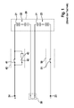
- FIG. 1 the schematic diagram of a battery system with such a traction battery 20 is shown.
- the battery 20 includes a plurality of battery cells 21 Simplification of the presentation in FIG. 1 only two battery cells have been designated by reference numeral 21. Traction batteries in hybrid and electric vehicles are usually modular. Here, from at least two individual battery cells 21, which are connected in series or in parallel, battery modules (in FIG. 1 not shown).
- the battery 20 is formed of two battery cell circuits 22, 23 each including a plurality of battery cells 21 connected in series. These battery cell circuits 22, 23 or cell modules are each connected to a battery terminal 24, 25 and to a terminal of a service connector 30.
- the positive battery terminal 24 is connectable to the battery 20 via a disconnecting and charging device 40 including a disconnect switch 41 connected in parallel to a series circuit of a charging switch 42 and a charging resistor 43.
- the negative battery terminal 25 is connectable to the battery 20 via a separator 50 which includes a further circuit breaker 51.
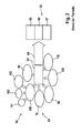
- FIG. 2 a diagram 60 in which various failure mechanisms 61 of lithium-ion batteries and their consequences 62 are highly schematic. These illustrated failure mechanisms 61 may result in a thermal runaway 64 of the battery cells 21 due to an inadmissible temperature increase 63. When a thermal runaway occurs 64, it can lead to a fire of the battery cells 66 or even bursting 67 of the battery cells 21 due to an emission of gas 65, which may occur, for example, when opening a burst valve as a result of increased battery cell internal pressure. Therefore, the occurrence of thermal runaway 64 in the use of the battery cells 21 in traction batteries most likely to be near 1 must be precluded.
- Thermal runaway 64 may occur in the event of overcharging 70 of a battery cell 21 as a result of a total discharge 80 of a battery cell 21 during the subsequent charging process or in the event of excessively high charging. and discharge currents of the battery cell 21, which may arise, for example, an external short circuit 90 occur. Further, thermal runaway 64 may also occur in the presence of a battery cell internal short circuit 100, which may arise, for example, as a result of a strong mechanical force during an accident 101 or as a result of the formation of battery cell internal dendrites 102, such as in the presence of excessive charging currents at low temperatures can arise.
- a thermal runaway 64 may also occur as a result of internal battery cell short circuits, which may be caused by contaminants of the battery cells 21, in particular by metallic foreign particles 103 present in the battery cells 21.
- a thermal runaway 64 may also occur in the event of an impermissible heating of the battery cells 110, which may arise, for example, as a result of a vehicle fire, or in the event of an overload of the battery cells 120.
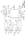
- FIG. 3 the schematic diagram of a known from the prior art battery system is shown, which includes a traction battery 20 with multiple battery cells 21 and a battery management system (BMS).
- the electronics of the battery management system has a decentralized architecture in which the monitoring and control units 130 formed from the cell monitoring electronics (CSC electronics) of the battery cells 21 are designed as satellites which are respectively provided for monitoring the functional state of one or more battery cells 21 and via internal bus system 141 with a central battery control unit (BCU) 140 communicate.
- CSC electronics cell monitoring electronics
- BCU central battery control unit
- the electronics of the battery management system in particular the monitoring electronics of the battery cells 21, is required to protect the battery cells 21 from the critical, in FIG. 2 Protected states that can lead to a thermal runaway.
- a high cost is operated, on the one hand to protect the battery cells 21 from overloading by external causes, such as by a short circuit in the inverter of an electric drive, and on the other hand to avoid that the Battery cells 21 by a malfunction of the electronics of the battery management system, such as by a faulty detection of the battery cell voltages by the monitoring and control units 130, are at risk.
- the central battery control device 140 is configured to drive the disconnect switch (relay) 41 and the charge switch (relay) 42 of the disconnecting and charging device 40.
- the activation of the disconnecting switch 41 and the charging switch 42 by means of the battery control device 140 is symbolized in the drawing by the arrow 142.
- the central battery control unit 140 is designed to control the further disconnector (relay) 51 of the separator 50. The activation of the disconnecting switch 51 by means of the battery control device 140 is symbolized by the arrow 143.
- the central battery control unit 140 is connected via a high-voltage line 144, 145 to a respective other battery terminal 24, 25. Further, the central battery control device 140 includes current sensors 150, 160 that are configured to measure a current flowing through the traction battery 20.
- the battery controller 140 also communicates with a vehicle interface via a CAN bus 146. Information about the health of the vehicle may be provided to the battery controller 140 via the CAN bus.
- the aim is therefore to increase the safety of the battery system so that no unreasonable risk occurs.
- safety tests are required for lithium ion battery cells.
- UN transport tests have to be carried out.
- the test results must be assessed according to the EUCAR Hazard Levels (EUCAR Hazard Levels).
- EUCAR Hazard Levels The battery cells 21 must comply with predetermined minimum safety levels. To achieve this, extensive additional measures are taken in the battery cells, which are intended for use in traction batteries.
- a classification according to the danger level ASIL C is expected to establish, if the safety of the battery cells 21 can not be significantly increased.
- Such additional measures are taken by integrating so-called safety devices in the battery cells. In this case, the following safety devices are typically integrated in the battery cells.
- a battery cell incorporates an Overcharge Safety Device (OSD).
- OSD Overcharge Safety Device
- Such a Kochladeconstructionsvoriques causes the battery cell during an overcharge does not exceed an EUCAR security level 4.
- the permissible range of the battery cell voltage ends at 4.2 V.
- the battery cell builds up such a high internal pressure from a battery cell voltage of about 5 V that a membrane of the overcharging safety device is arched outward and the battery cell is electrically short-circuited.
- the battery cell is discharged until a battery-internal fuse is activated.
- the short circuit of the battery cell between the two poles of the battery cell is maintained via the overcharging safety device.
- a battery cell fuse (Cell Fuse) is integrated into the battery cell.
- Cell Fuse Battery Fuse
- This fuse integrated in the battery cell is a very effective protection instrument at the battery cell level, but causes considerable problems when installing the battery cells in a series circuit of a battery module or in a battery system. There, these measures are rather counterproductive.
- a nail cell penetration safety device (Nail Penetration Safety Device (NDS)) is also integrated in a battery cell.
- NDS Near-Fielding Safety Device
- a nail penetration safety device protects the battery cell by establishing such a defined short-circuit path upon penetration of a nail or a pointed object into the battery cell, which does not lead to such strong local heating of the battery cell in the area of nail entry, which leads to a local melting of the existing separator could.
- a functional safety layer is also integrated into a battery cell.
- the functional safety layer is realized by the ceramic coating of one of the two electrodes of the battery cell, preferably by the ceramic coating of the anode.
- shock Safety Device In a battery cell also a shock safety device (Crush Safety Device) is integrated.
- the shock safety device has a similar operation as the nail penetration safety device.
- a strong mechanical deformation of the battery cell housing With a strong mechanical deformation of the battery cell housing, a defined short-circuit path is provided in the battery cell, which prevents strong local heating of the battery cell and thereby increases the safety of the battery cell.
- a battery module with a battery cell circuit having a plurality of battery cells and with a monitoring and control unit for monitoring the functional state of the battery module is provided.
- the battery module has a coupling unit with power semiconductors connected in a half-bridge arrangement for coupling the battery cell circuit to output terminals of the battery module.
- the battery module has a discharge circuit coupled to the battery cell circuit for rapid discharging of the battery module. The coupling unit and the discharge circuit can be controlled by the monitoring and control unit.
- a method for monitoring a battery module by means of a monitoring and control unit arranged in the battery module.
- the battery module is operated by means of a coupling unit comprising half-bridge arrangement switched power semiconductors for coupling the battery cell circuit of the battery mode to the output terminal of the battery module. If, during monitoring of the battery module by the monitoring and control unit, an error situation or danger situation of the battery module is detected, then the battery module by means of the coupling unit and / or by means of a coupled to the battery cell circuit of the battery module and arranged in the battery module discharge circuit, for fast discharge of the Battery mode is provided, put in a safe state.
- a battery system that has a battery with at least one battery string, in which several of the Battery modules according to the invention are arranged.
- the battery system comprises a battery management system, which is designed to communicate with the monitoring and control units of the battery modules.
- An advantage of the invention is that an intrinsically safe battery module is available, wherein the battery module can not only be operated very gently due to the controllable coupling circuit and in which an imminent damage of the battery module can be prevented by appropriate control of the coupling circuit.
- an additional safety feature is provided by providing an internal mechanism through the integrated discharging circuit for quickly discharging the battery module, with which, independently of discharge or charging currents impressed on external contacts such as the output terminals of the battery module, internal fast or ultra-fast discharging , especially in dangerous or emergency situations, can be performed.
- the coupling unit may comprise two half-bridges, each comprising a coupled to a positive pole of the battery cell circuit first power semiconductor, coupled to a negative pole of the battery circuit second power semiconductor and a center terminal and via the respective center terminal with a respective other output terminal of the battery module are connected.
- the battery module is preferably configured to operate in a normal operation, the coupling unit by means of control by the monitoring and control unit such that either a battery module voltage in positive or negative orientation or no battery cell voltage applied to the output terminals of the battery module.
- the battery module can thus be designed with a reversible output voltage. More specifically, the battery module may be modified be reversed polarity of an output voltage provided at its output terminals, so that the battery module can deliver the battery module voltage in a positive or negative orientation.
- the battery module according to the invention is particularly suitable for use in three-phase battery systems with adjustable output voltages, which are referred to as battery direct inverter, or generally in multi-phase battery systems with adjustable output voltages.
- the monitoring and control unit according to the invention is designed, in the presence of a battery cell voltage and / or battery module voltage whose amount exceeds a first voltage limit, and / or in the presence of a battery cell voltage and / or battery module voltage, the amount of which falls below a second voltage limit to put the power semiconductors of the coupling unit in a switching state in which no current flows through the battery module.
- the battery module is set in a safe state by a first power semiconductor of the half-bridge is turned on, so that a first output terminal and a second output terminal of the battery module are conductively connected, and a second power semiconductor of the same half-bridge off becomes.
- a coupling unit of two, in particular a full bridge forming, half bridges two power semiconductors connected to the first output terminal or two power semiconductors connected to the second output terminal can be switched on in each case.
- the monitoring and control unit detects an impending deep discharge starting from the battery module operating in normal operation by falling below a second limit of a battery cell voltage and / or battery module voltage, after which the battery module is transferred to a safe state in which no current flows through the battery module.
- the battery module according to the invention comprehensive battery system outward deliverable current flows only through the present in the battery module power semiconductor or semiconductor switch.
- the monitoring and control unit according to the invention is also adapted, in the presence of a charging current whose amount exceeds a predetermined or suitably selected charging current limit and / or in the presence of a (impressed outer) discharge, the amount of a predetermined or suitable selected charging current limit, to put the power semiconductor of the coupling unit in a switching state in which no current flows through the battery module.
- the monitoring and control unit detects, starting from the battery module operating in normal operation, an imminent overload due to excessively high discharge currents which, for example, can occur as a result of an external short circuit of the battery due to an error in the inverter.
- the battery module is transferred to a safe state in which no current flows through the battery module.
- the battery module is protected against loading with impermissibly high discharge currents.
- the monitoring and control unit recognizes, starting from the battery module operating in normal operation, an imminent overloading of the battery module due to excessive charging currents, the battery module then being transferred to the safe state, in which no more current flows through the battery module Battery module flows.
- the battery module is protected against loading with impermissibly high charging currents. This is particularly advantageous, for example, in the presence of very low temperatures at which the battery cells of the battery cell circuit of the battery module are particularly sensitive with respect to an educated on the anode lithium coating (lithium plating).
- the battery module via one or possibly two half-bridges, that is parallel over two half-bridges, to be discharged.
- the battery module does not release any voltage at its output terminals and, nevertheless, is nevertheless slowly discharged.
- a power semiconductor operated in particular as a controllable resistor is designed in this case including its thermal connection and cooling in accordance with the requirements.
- the monitoring and control unit is designed to detect the presence of a dangerous situation based on an evaluation of a measured cell temperature and / or battery module temperature and / or based on an evaluation of the battery cell voltages or the battery module voltage.
- a danger situation can be detected, in particular, at a cell temperature or battery module temperature exceeding a predetermined temperature limit and / or a voltage dip of the battery module voltage.
- the danger situation can also be detected by information communicated in particular by a battery management system.
- the monitoring and control unit may also be provided, in the presence of the
- Danger situation for discharging the battery module by means of at least one of the two half-bridges to power the power semiconductor of the coupling unit such that the first or the second power semiconductor of a half-bridge is turned on and the second or the first power semiconductor of the same half-bridge operates in the so-called active operation as a controllable resistance, and preferably the the first and the second power semiconductor of the other half-bridge is turned off or the first or the second power semiconductors of the two half-bridges are turned on and the second or the first power semiconductors of the two half-bridges operate in active operation.
- the discharge circuit when the danger situation is detected, the discharge circuit is activated for fast discharging of the battery module.
- the discharge circuit hereinafter also referred to as ultrafast discharge circuit (Ultra Fast Discharge Device) (UFDD) will be discharged as soon as possible.
- UFD Ultra Fast Discharge Device
- the realizable discharge currents are in particular not limited due to thermal power loss, which results, for example, in a power semiconductor operated as a controllable resistor or can be imposed on the power semiconductors in continuous operation.
- the battery module can be discharged simultaneously in a dangerous situation via the coupling unit, wherein in one in the half bridges a power semiconductor turned on and the other power semiconductor is operated in an active operation as a controllable resistor.
- the discharge circuit may comprise a series circuit with a resistor and a power semiconductor.
- the discharge circuit may in particular comprise a thyristor.
- the discharge circuit may comprise a drop-down circuit having a drain switch and a drain resistor.
- the detection of a dangerous situation due to the detection of a dangerous situation according to the invention, it is particularly advantageous to reliably detect, in particular, the performance of a test procedure during which the battery module is tested or other situations comparable to the battery module.
- the electronics of the monitoring and control unit according to the invention recognizes via the evaluation of a battery cell voltage and / or the battery module voltage that the Battery module is discharged via currents, without it being operated.
- the detection of this process can be done for example via a voltage dip of the battery module.
- the discharge of the battery module is triggered immediately via the discharge circuit according to the invention, and the battery module is then discharged substantially via the discharge circuit.
- the discharge of the battery module can be assisted via the two half-bridges.
- the battery module If the battery module is exposed to strong heating, this can be detected by the electronics of the monitoring and control unit according to the invention. As a result, the discharge of the battery module is triggered immediately, for example via the discharge circuit according to the invention and the battery module is discharged in good time via the discharge circuit.
- the electrically intrinsically safe battery module according to the invention in conjunction with the coupling unit arranged in the battery module and the monitoring and control unit, is designed so securely that, compared to a conventional battery management system, much less stringent requirements now need to be made in the battery system according to the invention.
- many previously typically performed, but not targeted measures such as equipping a battery module with an integrated
- the inventive electrically intrinsically safe battery module in conjunction with the coupling unit, the discharge circuit (ultrafast discharge circuit), and monitoring and control unit can be performed so sure that, compared to the prior art, now much lower requirements can be made to a battery management system.
- the measures implemented in the battery module for increasing the security in the presence of strong mechanical force effects can be omitted or at least much easier to implement, since the requirements on the part of the battery module are now much lower. It is possible that on the battery module and the battery cells arranged therein the battery cell circuit while strong mechanical forces, such as those simulated in UN transport tests, can safely act. This also applies in particular to a penetration of the battery cells or the battery module with pointed objects by means of a nail penetration test and / or a strong deformation of a battery cell or of the battery module by means of impacts with respect to all three spatial axes.
- the battery module can protect itself against impermissible operating states by means of the monitoring and control unit according to the invention, without having to depend on, for example, fuse functions of the electronics of a battery management system.
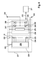
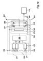
- the battery module 221 according to the first embodiment of the invention comprises a battery cell circuit 226 having a plurality of battery cells 21.
- the battery cell circuit 226 is here a series circuit, but in other embodiments of the invention may also comprise a parallel connection or a combination of a parallel connection and a series circuit.
- the battery cells are connected to a cell monitoring electronics (CSC) 228, which is provided for monitoring the individual battery cells 21.
- CSC cell monitoring electronics
- the cell monitoring electronics 228 is implemented by a central cell monitoring electronics, which is connected to all battery cells 21 and in particular can control a cell balancing.
- the battery module 221 further has a coupling unit, which is formed from a half bridge 240 with a first and a second power semiconductor 241, 242. Parallel to the power semiconductors 241, 242, a diode 260 is connected in each case, the forward direction of which extends counter to the forward direction of the corresponding power semiconductor 241, 242.
- the half-bridge 240 is connected to a first, the first power semiconductor (the first power semiconductor switch of the half-bridge from the FIG. 4 ) 241 associated with a positive pole 222 of the battery cell circuit 226 and at a second, the second power semiconductor 242 (the second power semiconductor switch of the half-bridge from the FIG. 4 ) associated with the negative terminal 223 of the battery cell circuit 226.
- the half bridge 240 is further connected at a center terminal to a first output terminal 224 of the battery module 221.
- the battery module 221 further comprises a monitoring and control unit 230 connected in parallel with the battery cell circuit 226 for monitoring the functional state of the battery cells 21 or the battery module 221.
- the monitoring and control unit 230 is equipped with an integrated drive for the power semiconductors 241, 242.
- FIG. 4 Also shown is a battery management system 211 for a battery system having a plurality of battery modules 221 according to the invention.
- the battery management system 211 is designed to communicate with the monitoring and control unit 230 or to exchange information.
- the exchange of information between the battery management system 211 and the monitoring and control unit 20 is symbolized by the double arrow 215.
- the monitoring and control unit 230 communicates with the cell monitoring electronics 228, which is configured as a central cell monitoring electronics 229 for all of the battery cells 228.
- the communication 235 can take place, for example, via a bus, in particular via a wired bus, for example a CAN bus or via FlexRay.
- the invention is not limited to a wired bus. In the following, therefore, if a (wired) bus is mentioned, in many cases the communication can also take place via wireless connections, such as Bluetooth.
- the monitoring and control electronics 230 are transmitted by the central cell monitoring electronics 229 in particular voltage and / or current measured values, which are further processed by the monitoring and control unit 230 for security monitoring, as shown below.
- the first power semiconductor 241 of the half-bridge 240 is turned off and the second Power semiconductor 242 is turned on. Since the battery module voltage is within the range U min_modul and U max_modul , the diode 260 of the first power semiconductor 241 blocks even in imminent overcharge, for example in a malfunction when charging the battery or the battery module 221. This can safely prevent further charging of the battery module 221 become.
- the first power semiconductor 241 of the half-bridge 240 is turned off and the second power semiconductor 242 is turned on. There then flows no more current through the battery module 221.
- the first power semiconductor 241 of the half-bridge 240 is turned off and the second power semiconductor 242 is turned on. Then, no current flows through the battery module 221. The battery module 221 is thus protected against a load with excessively high discharge currents.
- the monitoring and control unit 230 Recognizes the monitoring and control unit 230, starting from the normal operation of the battery module 221 impending overload of the battery module 221 by excessive charging currents, for example, at very low temperatures in which the battery cells 21 of the battery cell circuit 226 is particularly sensitive to an educated especially on the anode lithium coating,
- the monitoring and control unit 230 By means of the monitoring and control unit 230, the first power semiconductor 241 of the half-bridge 240 turned off and the second power semiconductor 242 is turned on. Then, no current flows through the battery module 221.
- the battery module 221 is thus protected from loading with impermissibly high charging currents.
- the battery module 221 can be discharged via the half bridge 240.
- the second power semiconductor 242 is turned on and the first power semiconductor 241 is operated in so-called active operation as a controllable resistor.
- the battery module 221 then outputs no voltage at its output terminals 224, 225 and is nevertheless slowly discharged.
- the realizable discharge currents are limited by the thermal power loss that can be imposed on the power semiconductor 241 operated as a controllable resistor in continuous operation.
- a power semiconductor 241 operated in particular as a controllable resistor, including its thermal connection and cooling, will therefore be designed in accordance with the requirements.
- the battery module 221 according to the first embodiment of the invention further includes a discharge circuit 270 as an Ultra Fast Discharge Device (UFDD).
- the discharge circuit 270 is provided in the battery module 221 for discharging the battery cells 21 by means of a discharge current flowing through the discharge circuit 270. If the monitoring and control unit 230 of the intrinsically safe battery module 221 according to the invention is informed by a battery management system 211 which is arranged in a battery system having a plurality of such battery modules 221 that the vehicle in which the battery system according to the invention has been installed has had an accident, the battery module becomes 221 discharged via the discharge circuit 270 quickly. In order to support the discharge circuit 270, the battery module 221 can also be discharged via the half-bridge 240 at the same time.
- UDD Ultra Fast Discharge Device
- the second power semiconductor 242 of the half-bridge 240 is thus switched on by means of the monitoring and control unit 230.
- the battery module 221 then outputs at its terminals or output terminals 224, 225 no voltage during discharge.
- the discharge circuit 270 may be configured so that the battery module 221 can be discharged with very large discharge currents near the short circuit. The battery module 221 is thus brought into a safe state very quickly. In this way, situations can be mastered at the vehicle level where the battery module 221 is mechanically severely deformed or penetrated by sharp objects.
- the first power semiconductor 241 can also be operated in active operation as a controllable resistor by means of the monitoring and control unit 230.
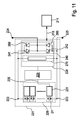
- the battery module 221 according to the invention is shown according to a second embodiment of the invention.
- the discharge circuit (UFDD) 270 shown in more detail and here comprises a connected between the positive terminal 222 and the negative terminal 223 of the battery cell circuit 226 series circuit of a power semiconductor 271 and a resistor 272nd
- the invention is not limited to a particular embodiment of the (ultrafast) discharge circuit 270. So be in the FIGS. 6 and 7 Further exemplary embodiments of the ultrafast discharge circuit (UFDD) 270 are shown.
- the discharge circuit 270 is one of the essential functional units in order to obtain an intrinsically safe battery module 221, and with which the battery module 221 is to be quickly brought to a safe state by discharging.
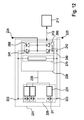
- FIG. 6 an implementation of the discharge circuit 270 is shown, which is based on the use of a (short circuit) thyristor 273. Thyristors are characterized by exceptional robustness and current carrying capacity and are therefore suitable for the present application, semiconductor devices.
- the local realization of the ultrafast discharge circuit 270 comprises a series connection of an ohmic resistor 272 and a Kurz gleichthyristors 273.
- the ohmic resistance 272 can either via the line resistances and the Contact resistors 274, 275 of the short circuit or be realized via a dedicated component.
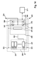
- FIG. 7 Another embodiment of the ultrafast discharge circuit 270 is shown, which is based on a Abtakt or a Abtaktscnies.
- the Abtakter can be constructed on the basis of an on and off electronic semiconductor valve 276 and a Abtaktwiderstand 272, wherein the semiconductor valve 276 has been controlled by the monitoring and control unit 230 according to the invention.
- the ohmic resistance of the Abtaktwiderstandes 272 limited together with the internal resistance of the battery module 221 and the battery cells 21, the maximum discharge during the rapid discharge of the battery module 221.
- For the on and off switchable electronic semiconductor switch 276 are particularly MOSFETs, as these due to the low requirements of the reverse voltage can be realized with very low on-resistance.
- An energy extraction from the battery module 221 can be controlled via the Abtaktscnies.
- energy can quickly be taken from the battery module 221 at the beginning of the discharge with a continuously switched on Abtakter.
- the drain resistor 272 and the Abtaktschalters 276 can then be changed to a pulsed operation or in a block operation.
- Inverse diodes 277, 278, which are connected in parallel, are shown.
- the inventive ultrafast discharge circuit 270 can thus be used for the realization of an intrinsically safe battery module 221.
- the battery module 221 can be protected against overcharging, over-discharging and overloading by excessively high charging and discharging currents.
- the limits for the electrical safety can be adjusted dynamically, for example as a function of the temperature of the battery cell 21.
- the battery module 221 is also intrinsically safe even with strong mechanical forces, as they can occur, for example, in an accident.
- the battery module 221 is discharged as quickly as possible upon detection of a critical condition via the discharge circuit 270.
- the battery module 221 is thus intrinsically safe in the event of severe heating.
- the battery module 221 is discharged as quickly as possible upon detection of a critical condition via the discharge circuit 270.
- the design of the discharge circuit 270 may be such that the discharge current does not exceed a maximum permissible maximum short-circuit current for the battery module 221.
- the resulting short-circuit current path depends on the specific conditions. Therefore, the behavior of a battery module can not be accurately predicted and is not reproducible. This disadvantage can be avoided with the discharge circuit presented here.
- the voltage of the battery module 221 via the half-bridge 240 can be specified exactly. If the second power semiconductor 242 of the half-bridge 240 is also automatically switched on when the discharge circuit 270 is activated, the intrinsically safe battery module 221 has the voltage 0V at its output terminals 224, 225, while the rapid discharge takes place via the discharge circuit 270.
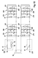
- FIG. 8 the schematic diagram of a battery module 221 is shown according to a further embodiment of the invention.
- the battery module 221 here has two half bridges 240, 250. More specifically, the battery module 221 includes FIG. 8 a battery cell circuit 226 and a coupling unit consisting of a first half bridge (the right half bridge from the FIG. 9 ) 240 with a first and a second power semiconductor 241, 242 and a second half-bridge (the left half-bridge from the FIG. 9 ) 250 with a first and a second power semiconductor 251, 252 is formed.
- the two half bridges 240, 250 together form a full bridge with four power semiconductors 241, 242, 251, 252. Parallel to the power semiconductors 241, 242, 251, 252, a diode 260 is connected in each case whose forward direction is opposite to the forward direction of the corresponding power semiconductor 241, 242 , 251, 252 runs.
- the first half-bridge 240 is connected to a first, the first power semiconductor (the first power semiconductor switch of the right half-bridge from the FIG. 9 ) 241 associated with a positive pole 222 of the battery cell circuit 226 and at a second, the second power semiconductor 242 (the second Power semiconductor switch of the right half-bridge from the FIG. 9 ) associated with the negative terminal 223 of the battery cell circuit 226.
- the first half-bridge 240 is further connected at a middle terminal to a first output terminal 224 of the battery module 221.
- the second half-bridge 250 is connected to a first, the first power semiconductor (the first power semiconductor switch of the left half-bridge from the FIG. 9 ) Associated with the positive terminal 222 of the battery cell circuit 226 and at a second, the second power semiconductor (the second power semiconductor switch of the left half bridge from the FIG. 9 ) 252 associated with the negative terminal 223 of the battery cell circuit 226.
- the second half-bridge 250 is further connected at a center terminal to a second output terminal 225 of the battery module 221.
- the safety features of the full bridge after FIG. 8 are similar to that of the half bridge after FIG. 4 , Due to the full-bridge arrangement, however, the power semiconductors 241, 242, 251, 252 can be controlled by means of the monitoring and control unit 230 according to the invention such that, during normal operation of the battery module 221, the battery module voltage is delivered to the output terminals 224, 225 in the positive orientation (+ U battery module ) should, the first power semiconductor 241 of the first half-bridge 240 and the second power semiconductor 252 of the second half-bridge 250 is turned on and the other two power semiconductors 242, 251 are turned off.
- the power semiconductors 241, 242, 251, 252 can be controlled by means of the monitoring and control unit 230 according to the invention such that, in normal operation, the battery module 226 is to deliver the battery module voltage to the output terminals 224, 225 in a negative orientation (-U battery module) second power semiconductors 242 of the first half-bridge 240 and the first power semiconductor 251 of the second half-bridge 250 turned on and the other two power semiconductors 241, 252 are turned off.
- the battery module 226 is to deliver the battery module voltage to the output terminals 224, 225 in a negative orientation (-U battery module) second power semiconductors 242 of the first half-bridge 240 and the first power semiconductor 251 of the second half-bridge 250 turned on and the other two power semiconductors 241, 252 are turned off.
- the power semiconductors 241, 242, 251, 252 can also be controlled by means of the monitoring and control unit 230 according to the invention such that during normal operation of the battery module 221 optionally also a functional state of the battery module 221 is adjustable, in which the battery module 221 emits no output voltage. In this state, either the first power semiconductors 241, 251 of the two half bridges 240, 250 are switched on and the other two power semiconductors 242, 252 are switched off or the second power semiconductors 242, 252 of the two half bridges 240, 250 are switched on and the other two power semiconductors 241, 251 are switched off ,
- the battery module 221 can be connected via one of the two half bridges 240, 250 or can be discharged in parallel via both half-bridges 240, 250, but the ultra-fast discharge circuit 270 is preferably used for charging.
- the monitoring and control unit 230 recognizes the evaluation of a battery cell voltage and / or the battery module voltage that the battery module 221 is discharged by currents without being operated. This can be done for example by detecting a voltage dip of the battery module 221.
- the monitoring and control unit 230 then immediately triggers the discharging of the battery module 221 via the discharge circuit 270 according to the invention, and the battery module 221 is then discharged substantially via the discharge circuit 270.
- the battery module 221 If the battery module 221 is exposed to strong heating, this can be detected by the monitoring and control unit 230. Since the time constants for the heating of the battery module 221 or the battery cells 21 are generally very high, a discharge of the battery module 221 can be effected in good time via the discharge circuit 270 according to the invention before a battery cell temperature and / or a battery module temperature exceed critical values. Optionally, a discharge of the battery module 221 can also take place via the two half bridges 240, 250. In order to support the discharge circuit 270, in particular the two second power semiconductors 242, 252 of the two half bridges 240, 250 are switched on by means of the monitoring and control unit 230. As a result, the battery module 221 becomes much more secure than in the prior art.
- the technology is a significant improvement, because otherwise very high negative voltages, which can be up to -400 V in electric vehicle batteries, for example, when activating a battery cell-internal fuse, which cause the electronics of a battery management system big problems.
- FIG. 9 the schematic diagram of a battery module 221 is shown according to another embodiment of the invention.
- the battery cells 21 are here each equipped with its own cell monitoring electronics 231.
- central cell monitoring electronics 229 are also present, although some functions of cell monitoring instead of in the central cell monitoring electronics 229 are now carried out in the individual battery cells 21 or in the corresponding battery cell cell monitoring electronics 231.
- the central cell monitoring electronics 229 communicates with the individual cell monitoring electronics 231 in the battery cells.
- This communication 235 can take place by means of a bus, to which both the central cell monitoring electronics 229 and the battery cell-specific cell monitoring electronics 231 are connected.
- the monitoring and control unit 230 according to the invention communicates in a manner similar to that according to FIGS FIGS. 4 . 5 , and 8th , with the central cell monitoring electronics 229.
- FIG. 10 the schematic diagram of a battery module according to yet another embodiment of the invention is shown.
- the battery cell-specific cell monitoring electronics 231 are connected in each case via their own, that is to say separate communication bus with the central cell monitoring electronics 229, which on the output side has a correspondingly higher number of interfaces for this purpose.
- FIG. 11 shows the block diagram of a battery module 221 according to yet another embodiment of the invention, wherein according to this
- a communication link 235 between a battery cell-own cell monitoring electronics 231 and the central cell monitoring electronics 229 is present, so that the central cell monitoring electronics 229 communicates with only one of the cell monitoring electronics 231 directly.
- the battery cell-specific cell monitoring electronics 231 communicate with each other, for example via a daisy-chain, so that all relevant battery cell data is transmitted first via the daisy-chain and then via the communication link, which is designated in the figures by reference numeral 235.
- the invention is not limited to such battery cell own cell monitoring electronics 231, which are arranged within a respective battery cell 21.
- a corresponding separate cell monitoring electronics 231 is arranged outside the battery cell 21 and connected to the battery cell 21, wherein optionally a central (main) cell monitoring electronics 229 may be present.
- FIGS. 12 to 14 show further embodiments of the invention, wherein in these embodiments, the monitoring and control unit 230 is directly connected to the battery cell-specific cell monitoring electronics 231, without the need for central cell monitoring electronics 229 is present. Thus, some cell monitoring tasks are performed directly in / on the battery cells 21, with determined measurement results and outputs of the cell monitoring electronics 231 being communicated directly to the monitoring and driving unit 230.
- the communication 235 between the monitoring and control unit 230 and the cell monitoring electronics 231 is similar to the embodiments described above in connection with the FIGS. 9 to 11 with the difference that the one or more communication buses are connected to the monitoring and driving unit 230 and not to a central cell monitoring unit.
- FIG. 12 an embodiment of the invention, in which the monitoring and control unit 230 via a bus with the cell monitoring electronics 231 is connected, and in FIG. 13 There are several communication links or buses between the monitoring and control unit 230 on the one hand and the respective cell monitoring electronics 231 on the other hand available.
- FIG. 14 an embodiment in which the cell monitoring electronics 231 communicate with each other, wherein one of the cell monitoring electronics 231 is connected to the monitoring and control unit 230.
- central cell monitoring electronics 229 and battery cell cell monitoring electronics 231 may be arranged in a battery module 221 having a monitoring and driving unit 230 with the unloading device 270 of the present invention. Examples of this were given above in connection with the FIGS. 8 to 14 discussed. So are those in the FIGS. 4 and 5 shown battery modules 221 is not limited to the illustrated there exemplary topology. Rather, the topology of the in the FIGS. 4 to 5 shown battery modules 221 analog also as in the FIGS. 9 to 14 be constructed circuit topologies constructed. In other words, although according to the FIGS. 4 and 5 the interconnection topology for the communication 235 between the monitoring and control unit 230 and the cell monitoring electronics 228, 229 of the in FIG. 8 in other embodiments, the interconnection topology may also be in the FIGS. 9 to 14 shown topologies, these alternative embodiments are not shown separately for the sake of brevity at this point.
- the battery modules 221 according to the invention presented here are not limited to lithium-ion battery cells. Rather, they may include other battery cell technologies, such as nickel-metal hybrid battery cells.
- the overcharge safety devices (OSDs) and the overcharging safety devices previously used can be used Battery cell fuses are eliminated.
- the measures used to increase the security of mechanical deformation or penetration, such as the establishment of a battery module with an integrated needle penetration safety device can either also be omitted or at least made much easier.
- ASIL classification QM quality assurance measures
- FIG. 15 shows the structure of a battery with an exemplary embodiment of the battery module 221 according to the invention.
- each battery module 221 of the battery shown there has a discharge circuit 270 and a coupling unit with a half-bridge 240.
- the explicit representation of the monitoring and control unit 230 arranged in each battery module 221 has been dispensed with.
- the battery modules 221 according to the invention are particularly suitable for use in battery direct inverters 210 with output voltages which can be set in stages.
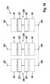
- FIG. 16 An example of the use of the electrically intrinsically safe battery modules 221 according to the invention presented here is that in FIG. 16 illustrated battery direct inverter 210.
- the in the FIG. 16 shown battery direct inverter 210 is a three-phase battery system with a step-adjustable output voltage.
- the battery direct inverter 210 comprises three battery strings 280, 290, 300, each of which has a series connection of a plurality of battery modules 221 according to the invention. These series connections of the battery strings 280, 290, 300 are connected to the positive battery branch poles 281, 291, 301 are each connected via a charging and disconnecting device 40 and with the negative battery bank poles 282, 292, 302 each via a separator 50.
- the battery cells or battery modules are controlled such that their operating parameters are within the respective limits which are necessary for safe operation.
- lithium ion battery cells are typically operated within a voltage range of Umin to Umax of 2.8V to 4.2V, or preferably 3.0V to 4.2V volts. This applies in particular to safety-relevant values Umin_safety or Umax_safety. However, these specifications apply to the voltages to be measured U battery cell at idle, that is, when no current flows through the battery cell. It is important to observe these limits, otherwise the electrodes may be damaged.
- the open circuit voltage of the battery cells depends essentially on their state of charge. In this case, typically a charge state SOC of 0%, at 3.5 V a charge state of 20%, and at 4.2 V a state of charge of 100% is assumed for a voltage U battery cell of 2.8 V, these values being in each case of type and Material of the cathode, the anode, and / or the electrolyte used.
- the battery cell voltages UBatteriezelle may differ from the above figures.
- the open circuit voltage is 3.5 V and the internal resistance of the battery cell at 25 ° C is 10 m ⁇ .
- the internal resistance of the battery cell can be as high as 50 m ⁇ , for example, at a temperature of 0 ° C
- the Umax value may be between 4.2V and 5.0V and the value of Umin is between 1.5V and 4.2V, preferably between 1.8V and 4.15V, but these values do not refer to the open circuit voltage.
- the allowable module open circuit voltage UBatteriemodul is between n x 2.8 V to n x 4.2 V, where n is the number of battery cells connected in series.
- Tmax-safety 46 ° C to 80 ° C, preferably 50 ° C to 60 ° C should not be exceeded.
- Tau B at which the battery cells are operated, should not exceed 40 ° C.
- the battery currents through the battery cells should not be outside a range of -1000 A to +1000 A, preferably -600 A to +600 A, more preferably -500 A to +500 A, even more preferably -450 A to +450 A, and more preferably -350 A to + 350 A, are.
- the internal pressure of a battery cell should not leave the pressure range of 2 bar to 8 bar, preferably 3 bar to 7 bar.
Landscapes
- Engineering & Computer Science (AREA)
- Power Engineering (AREA)
- Life Sciences & Earth Sciences (AREA)
- Sustainable Development (AREA)
- Sustainable Energy (AREA)
- Transportation (AREA)
- Mechanical Engineering (AREA)
- Secondary Cells (AREA)
- Charge And Discharge Circuits For Batteries Or The Like (AREA)
Abstract
Description
Die vorliegende Erfindung betrifft ein Batteriemodul mit einer Batteriezellschaltung mit mehreren Batteriezellen und mit einer Überwachungs- und Ansteuerungseinheit zur Überwachung des Funktionszustands des Batteriemoduls. Ferner betrifft die Erfindung ein Verfahren zum Überwachen eines Batteriemoduls mittels einer in dem Batteriemodul angeordneten Überwachungs- und Ansteuerungseinheit. Weiterhin betrifft die Erfindung ein Batteriesystem, das eine Batterie mit mindestens einem Batteriestrang, in dem mehrere Batteriemodule angeordnet sind, und ein Batteriemanagementsystem umfasst.The present invention relates to a battery module with a battery cell circuit having a plurality of battery cells and with a monitoring and control unit for monitoring the functional state of the battery module. Furthermore, the invention relates to a method for monitoring a battery module by means of a monitoring and control unit arranged in the battery module. Furthermore, the invention relates to a battery system comprising a battery having at least one battery string, in which a plurality of battery modules are arranged, and a battery management system.
Es ist üblich, Batterien für den Einsatz in Hybrid- und Elektrofahrzeugen als Traktionsbatterien zu bezeichnen, da diese Batterien für die Speisung elektrischer Antriebe eingesetzt werden. Um die bei Hybrid- und Elektrofahrzeugen geforderten Leistungs- und Energiedaten zu erzielen, werden einzelne Batteriezellen in Serie und teilweise zusätzlich parallel geschaltet. Bei Elektrofahrzeugen werden häufig 10 Zellen oder mehr in Serie verschaltet und die Batterien weisen Spannungen bis zu 450 V auf. Auch bei Hybridfahrzeugen wird üblicherweise die Spanungsgrenze von 60 V überschritten, welche bei Berührung durch Menschen als unkritisch eingestuft wird. In der
Die Batterie 20 ist aus zwei Batteriezellschaltungen 22, 23 ausgebildet, die jeweils mehrere in Reihe geschaltete Batteriezellen 21 umfassen. Diese Batteriezellenschaltungen 22, 23 beziehungsweise Zellmodule sind jeweils mit einem Batterieterminal 24, 25 und mit einem Anschluss eines Servicesteckers 30 verbunden.The
Das positive Batterieterminal 24 ist mit der Batterie 20 über eine Trenn- und Ladeeinrichtung 40 verbindbar, die einen Trennschalter 41 umfasst, der parallel zu einer Reihenschaltung aus einem Ladeschalter 42 und einem Ladewiderstand 43 geschaltet ist. Das negative Batterieterminal 25 ist mit der Batterie 20 über eine Trenneinrichtung 50 verbindbar, die einen weiteren Trennschalter 51 umfasst.The
Ferner zeigt
Ein thermisches Durchgehen 64 kann bei einem Überladen 70 einer Batteriezelle 21, als Folge einer Tiefentladung 80 einer Batteriezelle 21 während des anschließenden Ladevorganges oder bei Vorliegen von unzulässig hohen Lade- und Entladeströmen der Batteriezelle 21, die beispielsweise einem externen Kurzschlusses 90 entstehen können, auftreten. Ferner kann ein thermisches Durchgehen 64 auch bei Vorliegen eines batteriezellinternen Kurzschlusses 100 auftreten, der beispielsweise als Folge einer starken mechanischen Krafteinwirkung während eines Unfalls 101 oder als Folge der Bildung von batteriezellinternen Dendriten 102 entstehen kann, die beispielsweise bei Vorliegen von zu hohen Ladeströmen bei tiefen Temperaturen entstehen können. Weiterhin kann ein thermisches Durchgehen 64 auch als Folge von batteriezellinternen Kurzschlüssen auftreten, die durch bei der Fertigung entstehende Verunreinigungen der Batteriezellen 21, insbesondere durch in den Batteriezellen 21 vorhandenen metallischen Fremdpartikeln 103, verursacht werden können. Auch kann ein thermisches Durchgehen 64 bei Vorliegen einer unzulässigen Erwärmung der Batteriezellen 110, die beispielsweise als Folge eines Fahrzeugbrandes entstehen kann, oder bei Vorliegen einer Überlastung der Batteriezellen 120 auftreten.
In der
Die Elektronik des Batteriemanagementsystems, insbesondere die Überwachungselektronik der Batteriezellen 21, ist erforderlich, um die Batteriezellen 21 vor den kritischen, in
So wie bei dem in der
Ferner ist das zentrale Batteriesteuergerät 140 dazu ausgebildet, den Trennschalter (Relais) 41 und den Ladeschalter (Relais) 42 der Trenn- und Ladeeinrichtung 40 anzusteuern. Das Ansteuern des Trennschalters 41 und des Ladeschalters 42 mittels des Batteriesteuergeräts 140 wird in der Zeichnung mit dem Pfeil 142 symbolisiert. Auch ist das zentrale Batteriesteuergerät 140 dazu ausgebildet, den weiteren Trennschalter (Relais) 51 der Trenneinrichtung 50 anzusteuern. Das Ansteuern des Trennschalters 51 mittels des Batteriesteuergeräts 140 ist mit dem Pfeil 143 symbolisiert.Further, the central
Das zentrale Batteriesteuergerät 140 ist über eine Hochvoltleitung 144, 145 mit einem jeweils anderen Batterieterminal 24, 25 verbunden. Ferner umfasst das zentrale Batteriesteuergerät 140 Stromsensoren 150, 160, die dazu vorgesehen sind, einen durch die Traktionsbatterie 20 fließenden Strom zu messen. Das Batteriesteuergerät 140 kommuniziert auch mit einer Fahrzeugschnittstelle (vehicle interface) über einen CAN-Bus 146. Über den CAN-Bus können dem Batteriesteuergerät 140 Informationen über den Funktionszustand des Fahrzeuges bereitgestellt werden.The central
Bei der Verwendung eines aus dem Stand der Technik bekannten Batteriesystems wird somit angestrebt, die Sicherheit des Batteriesystems so zu erhöhen, dass keine unzumutbare Gefährdung auftritt. Dabei werden gemäß der ISO 26262 hohe Anforderungen an die funktionale Sicherheit des Batteriemanagementsystems gestellt, da eine Fehlfunktion der Elektronik, wie oben bereits erläutert, zu einer Gefährdung führen kann. Ferner sind für Lithiumlonen-Batteriezellen Sicherheitstests vorgeschrieben. Um die Batteriezellen transportieren zu dürfen, müssen beispielsweise UN Transport-Tests durchgeführt werden. Die Testergebnisse müssen gemäß den EUCAR Gefahrenstufen beziehungsweise Gefahrenlevels (EUCAR Hazard Levels) bewertet werden. Die Batteriezellen 21 müssen dabei vorgegebene Mindestsicherheitslevels einhalten. Um dies zu erreichen, werden in den Batteriezellen, die für den Einsatz in Traktionsbatterien vorgesehen sind, umfangreiche Zusatzmaßnahmen getroffen.When using a battery system known from the prior art, the aim is therefore to increase the safety of the battery system so that no unreasonable risk occurs. In accordance with the ISO 26262 high demands on the functional safety of the Battery management system provided as a malfunction of the electronics, as already explained above, can cause a hazard. Furthermore, safety tests are required for lithium ion battery cells. To be able to transport the battery cells, for example, UN transport tests have to be carried out. The test results must be assessed according to the EUCAR Hazard Levels (EUCAR Hazard Levels). The
Für Batteriemanagementsysteme für Batteriesysteme mit Traktionsbatterien 20 für Elektrofahrzeuge und Steckdosenhybride (Plug-in-Hybride) wird sich voraussichtlich eine Einstufung gemäß der Gefahrenstufe ASIL C etablieren, falls die Sicherheit der Batteriezellen 21 nicht signifikant erhöht werden kann. Solche Zusatzmaßnahmen werden dadurch getroffen, dass sogenannte Sicherheitsvorrichtungen (Safety Devices) in den Batteriezellen integriert werden. Dabei werden in den Batteriezellen typischerweise die im Folgenden angegebenen Sicherheitsvorrichtungen integriert.For battery management systems for battery systems with
In einer Batteriezelle wird eine Überladesicherheitsvorrichtung (Overcharge Safety Device) (OSD) integriert. Eine solche Überladesicherheitsvorrichtung bewirkt, dass die Batteriezelle bei einem Überladevorgang eine EUCAR Gefahrenstufe 4 nicht überschreitet. Der zulässige Bereich der Batteriezellspannung endet bei 4,2 V. Bei einem Überladevorgang baut die Batteriezelle ab einer Batteriezellspannung von etwa 5 V einen derart hohen Innendruck auf, das eine Membran der Überladesicherheitsvorrichtung nach außen gewölbt wird und die Batteriezelle elektrisch kurzgeschlossen wird. Als Folge davon wird die Batteriezelle solange entladen, bis eine batteriezellinterne Sicherung aktiviert wird. Der Kurzschluss der Batteriezelle zwischen den beiden Polen der Batteriezelle bleibt über die Überladesicherheitsvorrichtung erhalten.A battery cell incorporates an Overcharge Safety Device (OSD). Such a Überladesicherheitsvorrichtung causes the battery cell during an overcharge does not exceed an EUCAR security level 4. The permissible range of the battery cell voltage ends at 4.2 V. During an overcharging operation, the battery cell builds up such a high internal pressure from a battery cell voltage of about 5 V that a membrane of the overcharging safety device is arched outward and the battery cell is electrically short-circuited. As a result, the battery cell is discharged until a battery-internal fuse is activated. The short circuit of the battery cell between the two poles of the battery cell is maintained via the overcharging safety device.
Ferner wird eine Batteriezellsicherung (Cell Fuse) in die Batteriezelle integriert. Diese in der Batteriezelle integrierte Schmelzsicherung ist ein sehr wirksames Schutzinstrument auf Batteriezellebene, verursacht aber erhebliche Probleme beim Verbau der Batteriezellen in einer Serienschaltung eines Batteriemoduls beziehungsweise in einem Batteriesystem. Dort sind diese Maßnahmen eher kontraproduktiv.Furthermore, a battery cell fuse (Cell Fuse) is integrated into the battery cell. This fuse integrated in the battery cell is a very effective protection instrument at the battery cell level, but causes considerable problems when installing the battery cells in a series circuit of a battery module or in a battery system. There, these measures are rather counterproductive.
In einer Batteriezelle wird auch eine Nageleindringsicherheitsvorrichtung (Nail Penetration Safety Device (NDS)) integriert. Eine Nageleindringsicherheitsvorrichtung schützt die Batteriezelle, indem beim Eindringen eines Nagels oder eines spitzen Gegenstandes in die Batteriezelle ein derart definierter Kurzschlusspfad aufgebaut wird, der nicht zu einer so starken lokalen Erwärmung der Batteriezelle im Bereich des Nageleintrittes führt, welche zu einem lokalen Schmelzen des vorhandenen Separators führen könnte.A nail cell penetration safety device (Nail Penetration Safety Device (NDS)) is also integrated in a battery cell. A nail penetration safety device protects the battery cell by establishing such a defined short-circuit path upon penetration of a nail or a pointed object into the battery cell, which does not lead to such strong local heating of the battery cell in the area of nail entry, which leads to a local melting of the existing separator could.
In eine Batteriezelle wird auch eine Funktionssicherheitsschicht (Safety Function Layer (SFL)) integriert. Die Funktionssicherheitsschicht wird durch die keramische Beschichtung einer der beiden Elektroden der Batteriezelle, realisiert, vorzugsweise durch die keramische Beschichtung der Anode. Mittels der Funktionssicherheitsschicht kann bei einem Schmelzen des Separators ein flächiger Kurzschluss der Batteriezelle und damit eine extrem schnelle Umsetzung der elektrischen Energie der Batteriezelle in Verlustwärme verhindert werden.A functional safety layer (SFL) is also integrated into a battery cell. The functional safety layer is realized by the ceramic coating of one of the two electrodes of the battery cell, preferably by the ceramic coating of the anode. By means of the functional safety layer, a surface short circuit of the battery cell and thus an extremely rapid conversion of the electrical energy of the battery cell into heat loss can be prevented when the separator melts.
In eine Batteriezelle wird ferner auch eine Stoßsicherheitsvorrichtung (Crush Safety Device) integriert. Die Stoßsicherheitsvorrichtung weist eine ähnliche Funktionsweise wie die Nageleindringsicherheitsvorrichtung auf. Bei einer starken mechanischen Deformation des Batteriezellgehäuses wird ein definierter Kurzschlusspfad in der Batteriezelle bereitgestellt, der eine starke lokale Erwärmung der Batteriezelle verhindert und dadurch die Sicherheit der Batteriezelle erhöht.In a battery cell also a shock safety device (Crush Safety Device) is integrated. The shock safety device has a similar operation as the nail penetration safety device. With a strong mechanical deformation of the battery cell housing, a defined short-circuit path is provided in the battery cell, which prevents strong local heating of the battery cell and thereby increases the safety of the battery cell.
Bei den aktuell in Entwicklung befindlichen Batteriezellen sind insbesondere die Maßnahmen für die elektrische Sicherheit, die beispielsweise vor einem Überladen schützen oder einen Überstromschutz gewährleisten, mit erheblichem Aufwand verbunden. Diese Maßnahmen sind zudem nach dem Verbau einer Batteriezelle in ein Batteriemodul beziehungsweise in ein Batteriesystem tendenziell sogar eher kontraproduktiv anstatt sinnvoll. Beispielsweise kann bei einer Aktivierung der Schmelzsicherung einer Batteriezelle die Situation entstehen, dass die Elektronik des vorhandenen Batteriemanagementsystems (BMS) sehr hohen negativen Spannungen ausgesetzt wird. Dadurch entsteht auf Batteriesystemebene ein zusätzlicher Aufwand, da die Transportvorschriften auf Batteriezellenebene erfüllt werden müssen, ohne dass damit ein sonstiger Nutzen verbunden wäre.In the case of the battery cells currently being developed, the measures for electrical safety, which for example protect against overcharging or ensure overcurrent protection, are associated with considerable expense. Moreover, these measures tend to be rather counterproductive rather than meaningful after the installation of a battery cell in a battery module or in a battery system. For example, at activation of the fuse of a battery cell, the situation arises that the electronics of the existing battery management system (BMS) is exposed to very high negative voltages. This creates an additional expense on the battery system level, since the transport regulations must be met at the battery cell level, without any other benefit would be connected.
Erfindungsgemäß wird ein Batteriemodul mit einer Batteriezellschaltung mit mehreren Batteriezellen und mit einer Überwachungs- und Ansteuerungseinheit zur Überwachung des Funktionszustands des Batteriemoduls zur Verfügung gestellt. Dabei weist das Batteriemodul eine Koppeleinheit mit in Halbbrückenanordnung geschalteten Leistungshalbleitern zum Koppeln der Batteriezellschaltung mit Ausgangsterminals des Batteriemoduls auf. Ferner weist das Batteriemodul eine mit der Batteriezellschaltung gekoppelte Entladeschaltung zum schnellen Entladen des Batteriemoduls auf. Die Koppeleinheit und die Entladeschaltung sind durch die Überwachungs- und Ansteuerungseinheit ansteuerbar.According to the invention, a battery module with a battery cell circuit having a plurality of battery cells and with a monitoring and control unit for monitoring the functional state of the battery module is provided. In this case, the battery module has a coupling unit with power semiconductors connected in a half-bridge arrangement for coupling the battery cell circuit to output terminals of the battery module. Furthermore, the battery module has a discharge circuit coupled to the battery cell circuit for rapid discharging of the battery module. The coupling unit and the discharge circuit can be controlled by the monitoring and control unit.
Erfindungsgemäß wird auch ein Verfahren zum Überwachen eines Batteriemoduls mittels einer in dem Batteriemodul angeordneten Überwachungs- und Ansteuerungseinheit zur Verfügung gestellt. Das Batteriemodul wird mittels einer Koppeleinheit betrieben, die in Halbbrückenanordnung geschaltete Leistungshalbleiter zum Koppeln der Batteriezellschaltung des Batteriemodus an Ausgangsterminals des Batteriemoduls umfasst. Wenn beim Überwachen des Batteriemoduls durch die Überwachungs- und Ansteuerungseinheit eine Fehlersituation oder Gefahrsituation des Batteriemoduls feststellt wird, dann wird das Batteriemodul mittels der Koppeleinheit und/oder mittels einer mit der Batteriezellschaltung des Batteriemoduls gekoppelten und in dem Batteriemodul angeordneten Entladeschaltung, die zum schnellen Entladen des Batteriemodus vorgesehen ist, in einen sicheren Zustand versetzt.According to the invention, a method is also provided for monitoring a battery module by means of a monitoring and control unit arranged in the battery module. The battery module is operated by means of a coupling unit comprising half-bridge arrangement switched power semiconductors for coupling the battery cell circuit of the battery mode to the output terminal of the battery module. If, during monitoring of the battery module by the monitoring and control unit, an error situation or danger situation of the battery module is detected, then the battery module by means of the coupling unit and / or by means of a coupled to the battery cell circuit of the battery module and arranged in the battery module discharge circuit, for fast discharge of the Battery mode is provided, put in a safe state.
Ferner wird weiterhin ein Batteriesystem zur Verfügung gestellt, dass eine Batterie mit mindestens einem Batteriestrang aufweist, in dem mehrere der erfindungsgemäßen Batteriemodule angeordnet sind. Dabei umfasst das Batteriesystem ein Batteriemanagementsystem, das dazu ausgebildet ist, mit den Überwachungs- und Ansteuerungseinheiten der Batteriemodule zu kommunizieren.Furthermore, a battery system is provided that has a battery with at least one battery string, in which several of the Battery modules according to the invention are arranged. In this case, the battery system comprises a battery management system, which is designed to communicate with the monitoring and control units of the battery modules.
Die Unteransprüche zeigen bevorzugte Weiterbildungen der Erfindung.The dependent claims show preferred developments of the invention.
Ein Vorteil der Erfindung ist, dass ein eigensicheres Batteriemodul zur Verfügung steht, wobei das Batteriemodul aufgrund der ansteuerbaren Koppelschaltung nicht nur besonders schonend betrieben werden kann und bei der ein drohender Schaden von dem Batteriemodul durch entsprechende Steuerung der Koppelschaltung verhindert werden kann. Darüber hinaus wird eine zusätzliche Sicherheitsfunktion bereitgestellt, indem durch die integrierte Entladeschaltung zum schnellen Entladen des Batteriemoduls ein interner Mechanismus geschaffen wird, mit dem unabhängig von an äußeren Kontaktierungen wie beispielsweise an den Ausgangsterminals des Batteriemoduls aufgeprägten Entlade- oder Ladeströmen stattdessen intern ein schnelles oder ultraschnelles Entladen, insbesondere in Gefahr- oder Notfallsituationen, durchgeführt werden kann.An advantage of the invention is that an intrinsically safe battery module is available, wherein the battery module can not only be operated very gently due to the controllable coupling circuit and in which an imminent damage of the battery module can be prevented by appropriate control of the coupling circuit. In addition, an additional safety feature is provided by providing an internal mechanism through the integrated discharging circuit for quickly discharging the battery module, with which, independently of discharge or charging currents impressed on external contacts such as the output terminals of the battery module, internal fast or ultra-fast discharging , especially in dangerous or emergency situations, can be performed.
Gemäß einer besonderen Ausführungsform der Erfindung kann die Koppeleinheit zwei Halbbrücken aufweisen, die jeweils einen mit einem Pluspol des Batteriezellschaltung gekoppelten ersten Leistungshalbleiter, einen mit einem Minuspol der Batterieschaltung gekoppelten zweiten Leistungshalbleiter und einen Mittelanschluss umfassen und über den jeweiligen Mittelanschluss mit einem jeweils anderen Ausgangsterminal des Batteriemoduls verbunden sind.According to a particular embodiment of the invention, the coupling unit may comprise two half-bridges, each comprising a coupled to a positive pole of the battery cell circuit first power semiconductor, coupled to a negative pole of the battery circuit second power semiconductor and a center terminal and via the respective center terminal with a respective other output terminal of the battery module are connected.
Dabei ist das Batteriemodul bevorzugt dazu eingerichtet, in einem Normalbetrieb die Koppeleinheit mittels Ansteuerung durch die Überwachungs- und Ansteuerungseinheit derartig zu betreiben, dass wahlweise eine Batteriemodulspannung in positiver oder negativer Orientierung oder keine Batteriezellspannung an den Ausgangsterminals des Batteriemoduls anliegt.In this case, the battery module is preferably configured to operate in a normal operation, the coupling unit by means of control by the monitoring and control unit such that either a battery module voltage in positive or negative orientation or no battery cell voltage applied to the output terminals of the battery module.
Anschaulich gesagt kann das Batteriemodul somit mit umpolbarer Ausgangsspannung ausgeführt sein. Genauer, das Batteriemodul kann bezüglich einer an seinen Ausgangsterminals bereitgestellten Ausgangsspannung umgepolt werden, so dass das Batteriemodul die Batteriemodulspannung in positiver oder negativer Orientierung abgeben kann.To put it clearly, the battery module can thus be designed with a reversible output voltage. More specifically, the battery module may be modified be reversed polarity of an output voltage provided at its output terminals, so that the battery module can deliver the battery module voltage in a positive or negative orientation.
Aufgrund der Funktionalität des erfindungsgemäßen Batteriemoduls, die Batteriemodulspannung umzupolen, eignet sich die erfindungsgemäße Batteriemodul insbesondere für den Einsatz in dreiphasigen Batteriesystemen mit stufig einstellbaren Ausgangsspannungen, die als Batteriedirektinverter bezeichnet werden, beziehungsweise allgemein in mehrphasigen Batteriesystemen mit stufig einstellbaren Ausgangsspannungen.Due to the functionality of the battery module according to the invention umzupolen the battery module voltage, the battery module according to the invention is particularly suitable for use in three-phase battery systems with adjustable output voltages, which are referred to as battery direct inverter, or generally in multi-phase battery systems with adjustable output voltages.
Bei einer bevorzugten Ausführungsform der Erfindung ist die erfindungsgemäße Überwachungs- und Ansteuerungseinheit dazu ausgebildet, bei Vorliegen einer Batteriezellspannung und/oder Batteriemodulspannung, deren Betrag einen ersten Spannungsgrenzwert überschreitet, und/oder bei Vorliegen einer Batteriezellspannung und/oder Batteriemodulspannung, deren Betrag einen zweiten Spannungsgrenzwert unterschreitet, die Leistungshalbleiter der Koppeleinheit in einen Schaltzustand zu versetzen, bei dem durch das Batteriemodul kein Strom fließt.In a preferred embodiment of the invention, the monitoring and control unit according to the invention is designed, in the presence of a battery cell voltage and / or battery module voltage whose amount exceeds a first voltage limit, and / or in the presence of a battery cell voltage and / or battery module voltage, the amount of which falls below a second voltage limit to put the power semiconductors of the coupling unit in a switching state in which no current flows through the battery module.
Dies kann dadurch erfolgen, dass mit Hilfe der Halbbrücken das Batteriemodul in einen sicheren Zustand versetzt wird, indem ein erster Leistungshalbleiter der Halbbrücke eingeschaltet wird, so dass ein erstes Ausgangsterminal und ein zweites Ausgangsterminal des Batteriemoduls leitend verbunden werden, und ein zweiter Leistungshalbleiter derselben Halbbrücke ausgeschaltet wird. Ferner, bei Verwendung einer Koppeleinheit aus zwei, insbesondere eine Vollbrücke bildenden, Halbbrücken, können jeweils zwei mit dem ersten Ausgangsterminal verbundene Leistungshalbleiter oder zwei mit dem zweiten Ausgangsterminal verbundene Leistungshalbleiter eingeschaltet werden.This can be done by using the half bridges the battery module is set in a safe state by a first power semiconductor of the half-bridge is turned on, so that a first output terminal and a second output terminal of the battery module are conductively connected, and a second power semiconductor of the same half-bridge off becomes. Furthermore, when using a coupling unit of two, in particular a full bridge forming, half bridges, two power semiconductors connected to the first output terminal or two power semiconductors connected to the second output terminal can be switched on in each case.
Dies hat den Vorteil, dass die Überwachungs- und Ansteuerungseinheit eine drohende Überladung des im Normalbetrieb arbeitenden Batteriemoduls anhand einer Überschreitung eines ersten Grenzwertes der Batteriezellspannung oder Batteriemodulspannung erkennt, und das Batteriemodul dann günstigerweise nicht weiter aufgeladen und damit beispielsweise bei einer Fehlfunktion eines Batterieladegerätes sicher vor einer Überladung geschützt werden kann.This has the advantage that the monitoring and control unit detects impending overcharging of the battery module operating in normal operation based on an exceeding of a first limit value of the battery cell voltage or battery module voltage, and the battery module then expediently not charged further and thus, for example, in a malfunction of a battery charger can be safely protected from overcharging.
Ferner erkennt die Überwachungs- und Ansteuerungseinheit eine drohende Tiefentladung ausgehend von dem im Normalbetrieb arbeitenden Batteriemodul anhand einer Unterschreitung eines zweiten Grenzwertes einer Batteriezellspannung und/oder Batteriemodulspannung, woraufhin das Batteriemodul in einen sicheren Zustand überführt wird, bei dem kein Strom durch das Batteriemodul mehr fließt. Ein eventuell über ein gesamtes, das erfindungsgemäße Batteriemodul umfassendes Batteriesystems nach außen abgebbarer Strom fließt nur über die in dem Batteriemodul vorhandenen Leistungshalbleiter beziehungsweise Halbleiterschalter.Furthermore, the monitoring and control unit detects an impending deep discharge starting from the battery module operating in normal operation by falling below a second limit of a battery cell voltage and / or battery module voltage, after which the battery module is transferred to a safe state in which no current flows through the battery module. A possibly over an entire, the battery module according to the invention comprehensive battery system outward deliverable current flows only through the present in the battery module power semiconductor or semiconductor switch.
Bei einer weiteren bevorzugten Ausführungsform der Erfindung ist die erfindungsgemäße Überwachungs- und Ansteuerungseinheit auch dazu eingerichtet, bei Vorliegen eines Ladestroms, dessen Betrag einen vorgegebenen beziehungsweise geeignet gewählten Ladestromgrenzwert überschreitet und/oder bei Vorliegen eines (aufgeprägten äußeren) Entladestroms, dessen Betrag einen vorgegebenen beziehungsweise geeignet gewählten Ladestromgrenzwert überschreitet, die Leistungshalbleiter der Koppeleinheit in einen Schaltzustand zu versetzen, bei dem durch das Batteriemodul kein Strom fließt.In a further preferred embodiment of the invention, the monitoring and control unit according to the invention is also adapted, in the presence of a charging current whose amount exceeds a predetermined or suitably selected charging current limit and / or in the presence of a (impressed outer) discharge, the amount of a predetermined or suitable selected charging current limit, to put the power semiconductor of the coupling unit in a switching state in which no current flows through the battery module.
Somit erkennt die Überwachungs- und Ansteuerungseinheit ausgehend von dem im Normalbetrieb arbeitenden Batteriemodul eine drohende Überlastung durch zu hohe Entladeströme, die beispielsweise als Folge eines externen Kurzschlusses der Batterie durch einen Fehler im Inverter auftreten können. Dabei wird das Batteriemodul in einen sicheren Zustand überführt, in dem kein Strom durch das Batteriemodul fließt. Das Batteriemodul wird so vor einer Belastung mit unzulässig hohen Entladeströmen geschützt.Thus, the monitoring and control unit detects, starting from the battery module operating in normal operation, an imminent overload due to excessively high discharge currents which, for example, can occur as a result of an external short circuit of the battery due to an error in the inverter. In this case, the battery module is transferred to a safe state in which no current flows through the battery module. The battery module is protected against loading with impermissibly high discharge currents.
Ferner erkennt die Überwachungs- und Ansteuerungseinheit ausgehend von dem im Normalbetrieb arbeitenden Batteriemodul eine drohende Überlastung des Batteriemoduls durch zu hohe Ladeströme, wobei das Batteriemodul dann in den sicheren Zustand überführt wird, in dem kein Strom mehr durch das Batteriemodul fließt. Das Batteriemodul wird so vor einer Belastung mit unzulässig hohen Ladeströmen geschützt. Dies ist besonders vorteilhaft beispielsweise bei Vorliegen von sehr tiefen Temperaturen, bei denen die Batteriezellen der Batteriezellschaltung des Batteriemoduls besonders empfindlich hinsichtlich eines sich auf der Anode ausbildbareren Lithiumüberzugs (Lithium plating) sind.Furthermore, the monitoring and control unit recognizes, starting from the battery module operating in normal operation, an imminent overloading of the battery module due to excessive charging currents, the battery module then being transferred to the safe state, in which no more current flows through the battery module Battery module flows. The battery module is protected against loading with impermissibly high charging currents. This is particularly advantageous, for example, in the presence of very low temperatures at which the battery cells of the battery cell circuit of the battery module are particularly sensitive with respect to an educated on the anode lithium coating (lithium plating).
Mit anderen Worten, es kann in einem Fall, in dem der Elektronik der Überwachungs- und Ansteuerungseinheit des erfindungsgemäßen eigensicheren Batteriemoduls durch ein Batteriemanagementsystem beispielsweise eine entsprechende Information darüber mitgeteilt wird, das das Fahrzeug, in dem das erfindungsgemäße Batteriesystem eingebaut ist, einen Unfall hatte, das Batteriemodul über eine oder gegebenenfalls beiden Halbbrücken, das heißt parallel über zwei Halbbrücken, entladen werden. Während der Entladung des Batteriemoduls über eine der Halbbrücken gibt das Batteriemodul an seinen Ausgangsterminals keine Spannung ab und wird günstigerweise trotzdem langsam entladen. Ein insbesondere als steuerbarer Widerstand betriebener Leistungshalbleiter wird hierbei inklusive seiner thermischen Anbindung und Kühlung entsprechend den Anforderungen ausgelegt.In other words, in a case where the electronics of the monitoring and driving unit of the intrinsically safe battery module according to the present invention is notified by a battery management system, for example, corresponding information that the vehicle in which the battery system of the invention is installed has had an accident, the battery module via one or possibly two half-bridges, that is parallel over two half-bridges, to be discharged. During the discharge of the battery module via one of the half-bridges, the battery module does not release any voltage at its output terminals and, nevertheless, is nevertheless slowly discharged. A power semiconductor operated in particular as a controllable resistor is designed in this case including its thermal connection and cooling in accordance with the requirements.
Ferner ist gemäß einer weiteren, sehr vorteilhaften Ausführungsform der Erfindung die Überwachungs- und Ansteuerungseinheit ausgebildet, anhand einer Auswertung einer gemessenen Zelltemperatur und/oder Batteriemodultemperatur und/oder anhand einer Auswertung der Batteriezellspannungen beziehungsweise der Batteriemodulspannung das Vorliegen einer Gefahrsituation zu erkennen. Bei Auswertung der Zelltemperatur und/oder der Batteriemodulspannung kann eine Gefahrsituation insbesondere bei einer einen vorbestimmten Temperaturgrenzwert überschreitenden Zelltemperatur oder Batteriemodultemperatur und/oder einem Spannungseinbruch der Batteriemodulspannung erkannt werden. Die Gefahrsituation kann auch anhand insbesondere durch ein Batteriemanagementsystem kommunizierter Information erkannt werden.Furthermore, according to a further, very advantageous embodiment of the invention, the monitoring and control unit is designed to detect the presence of a dangerous situation based on an evaluation of a measured cell temperature and / or battery module temperature and / or based on an evaluation of the battery cell voltages or the battery module voltage. When evaluating the cell temperature and / or the battery module voltage, a danger situation can be detected, in particular, at a cell temperature or battery module temperature exceeding a predetermined temperature limit and / or a voltage dip of the battery module voltage. The danger situation can also be detected by information communicated in particular by a battery management system.
Gemäß einer vorteilhaften Weiterbildung der Erfindung kann die Überwachungs- und Ansteuerungseinheit ferner dazu vorgesehen sein, bei Vorliegen derAccording to an advantageous embodiment of the invention, the monitoring and control unit may also be provided, in the presence of the
Gefahrsituation zum Entladen des Batteriemoduls mittels mindestens einer der beiden Halbbrücken die Leistungshalbleiter der Koppeleinheit derartig anzusteuern, dass der erste oder der zweite Leistungshalbleiter einer Halbbrücke eingeschaltet ist und der zweite oder der erste Leistungshalbleiter derselben Halbbrücke im sogenannten aktiven Betrieb als steuerbarer Widerstand arbeitet, und bevorzugt der erste und der zweite Leistungshalbleiter der anderen Halbbrücke ausgeschaltet ist oder die ersten oder die zweiten Leistungshalbleiter der beiden Halbbrücken eingeschaltet sind und die zweiten oder die ersten Leistungshalbleiter der beiden Halbbrücken im aktiven Betrieb arbeiten.Danger situation for discharging the battery module by means of at least one of the two half-bridges to power the power semiconductor of the coupling unit such that the first or the second power semiconductor of a half-bridge is turned on and the second or the first power semiconductor of the same half-bridge operates in the so-called active operation as a controllable resistance, and preferably the the first and the second power semiconductor of the other half-bridge is turned off or the first or the second power semiconductors of the two half-bridges are turned on and the second or the first power semiconductors of the two half-bridges operate in active operation.
Nach einer bevorzugten Ausführungsform der Erfindung wird, wenn die Gefahrsituation erkannt wird, die Entladeschaltung zum schnellen Entladen des Batteriemoduls aktiviert. Somit kann, wenn der Elektronik der Überwachungs- und Ansteuerungseinheit des erfindungsgemäßen eigensicheren Batteriemoduls von einem Batteriemanagementsystem mitgeteilt wird, dass das Fahrzeug, das mit dem erfindungsgemäßen Batteriesystem ausgestattet ist, einen Unfall hatte, die Batteriezelle über die Entladeschaltung, die im Folgenden auch als ultraschnelle Entladeschaltung (Ultra Fast Discharge Device) (UFDD) bezeichnet wird, schnellstmöglich entladen werden. Dadurch sind die realisierbaren Entladeströme insbesondere nicht aufgrund thermischer Verlustleistung begrenzt, die sich beispielsweise bei einem als steuerbaren Widerstand betriebenen Leistungshalbleiter ergibt beziehungsweise den Leistungshalbleitern im Dauerbetrieb auferlegt werden kann. Jedoch kann, um die Entladeschaltung zu unterstützen, das Batteriemodul in einer Gefahrsituation gleichzeitig über die Koppeleinheit entladen werden, wobei in einer in der Halbbrücken ein Leistungshalbleiter eingeschaltet und der andere Leistungshalbleiter in einem aktiven Betrieb als steuerbarer Widerstand betrieben wird.According to a preferred embodiment of the invention, when the danger situation is detected, the discharge circuit is activated for fast discharging of the battery module. Thus, if the electronics of the monitoring and control unit of the intrinsically safe battery module according to the invention is informed by a battery management system that the vehicle equipped with the battery system according to the invention had an accident, the battery cell via the discharge circuit, hereinafter also referred to as ultrafast discharge circuit (Ultra Fast Discharge Device) (UFDD) will be discharged as soon as possible. As a result, the realizable discharge currents are in particular not limited due to thermal power loss, which results, for example, in a power semiconductor operated as a controllable resistor or can be imposed on the power semiconductors in continuous operation. However, in order to support the discharge circuit, the battery module can be discharged simultaneously in a dangerous situation via the coupling unit, wherein in one in the half bridges a power semiconductor turned on and the other power semiconductor is operated in an active operation as a controllable resistor.
Die Entladeschaltung kann eine Serienschaltung mit einem Widerstand und einem Leistungshalbleiter umfassen. Dabei kann die Entladeschaltung insbesondere einen Thyristor umfassen.The discharge circuit may comprise a series circuit with a resistor and a power semiconductor. In this case, the discharge circuit may in particular comprise a thyristor.
Ferner kann die Entladeschaltung eine Abtaktschaltung mit einem Abtaktschalter und einem Abtaktwiderstand umfasst.Furthermore, the discharge circuit may comprise a drop-down circuit having a drain switch and a drain resistor.
Gemäß nach einem Aspekt der Erfindung können aufgrund der erfindungsgemäßen Erkennung einer Gefahrsituation vorteilhaft insbesondere auch das Durchführen eines Testvorganges, während dessen das Batteriemodul getestet wird, oder andere, für das Batteriemodul vergleichbare Situationen, zuverlässig erkannt werden.According to one aspect of the invention, due to the detection of a dangerous situation according to the invention, it is particularly advantageous to reliably detect, in particular, the performance of a test procedure during which the battery module is tested or other situations comparable to the battery module.
Wird das erfindungsgemäße Batteriemodul beispielsweise im Rahmen eines UN Transport-Tests einem Nageleindringtest (Nail Penetration Test) oder einem Stoßtest (Crush Test) unterzogen, erkennt die Elektronik der erfindungsgemäßen Überwachungs- und Ansteuerungseinheit über die Auswertung einer Batteriezellspannung und/oder der Batteriemodulspannung, dass das Batteriemodul über Ströme entladen wird, ohne dass es betrieben wird. Die Erkennung dieses Vorganges kann beispielsweise über einen Spannungseinbruch des Batteriemoduls erfolgen. Als Folge davon wird sofort das Entladen des Batteriemoduls über die erfindungsgemäße Entladeschaltung ausgelöst, und das Batteriemodul wird dann im Wesentlichen über die Entladeschaltung entladen. Optional kann auch hier, wie bereits erläutert, eine Unterstützung der Entladung des Batteriemoduls über die beiden Halbbrücken erfolgen.If the battery module according to the invention is subjected to a nail penetration test or a crush test, for example, the electronics of the monitoring and control unit according to the invention recognizes via the evaluation of a battery cell voltage and / or the battery module voltage that the Battery module is discharged via currents, without it being operated. The detection of this process can be done for example via a voltage dip of the battery module. As a result, the discharge of the battery module is triggered immediately via the discharge circuit according to the invention, and the battery module is then discharged substantially via the discharge circuit. Optionally, as already explained, the discharge of the battery module can be assisted via the two half-bridges.
Wird das Batteriemodul einer starken Erwärmung ausgesetzt, so kann dies über die Elektronik der erfindungsgemäßen Überwachungs- und Ansteuerungseinheit erkannt werden. Als Folge davon wird sofort das Entladen des Batteriemoduls beispielsweise über die erfindungsgemäße Entladeschaltung ausgelöst und das Batteriemodul wird über die Entladeschaltung rechtzeitig entladen.If the battery module is exposed to strong heating, this can be detected by the electronics of the monitoring and control unit according to the invention. As a result, the discharge of the battery module is triggered immediately, for example via the discharge circuit according to the invention and the battery module is discharged in good time via the discharge circuit.
Das erfindungsgemäße elektrisch eigensichere Batteriemodul wird in Verbindung mit der in dem Batteriemodul angeordneten Koppeleinheit und der Überwachungs- und Ansteuerungseinheit so sicher ausgeführt, dass, im Vergleich zu einem herkömmlichen Batteriemanagementsystem, bei dem erfindungsgemäßen Batteriesystem nunmehr wesentlich geringere Anforderungen gestellt werden müssen. Darüber hinaus können zahlreiche bisher typischerweise durchgeführten, jedoch nicht zielführende Maßnahmen, wie beispielsweise das Ausstatten eines Batteriemoduls mit einer integriertenThe electrically intrinsically safe battery module according to the invention, in conjunction with the coupling unit arranged in the battery module and the monitoring and control unit, is designed so securely that, compared to a conventional battery management system, much less stringent requirements now need to be made in the battery system according to the invention. In addition, many previously typically performed, but not targeted measures, such as equipping a battery module with an integrated
Überladesicherheitsvorrichtung und/oder einer integrierten Batteriezellsicherung, entfallen.Overload safety device and / or an integrated battery cell backup eliminated.
Zusammenfassend kann das erfindungsgemäße elektrisch eigensichere Batteriemodul in Verbindung mit der Koppeleinheit, der Entladeschaltung (ultraschnelle Entladeschaltung), und Überwachungs- und Ansteuerungseinheit so sicher ausgeführt werden, dass, im Vergleich zum Stand der Technik, an ein Batteriemanagementsystem nunmehr wesentlich geringere Anforderungen gestellt werden können.In summary, the inventive electrically intrinsically safe battery module in conjunction with the coupling unit, the discharge circuit (ultrafast discharge circuit), and monitoring and control unit can be performed so sure that, compared to the prior art, now much lower requirements can be made to a battery management system.
Auch die in dem Batteriemodul durchgeführten Maßnahmen für die Erhöhung der Sicherheit bei Vorliegen von starken mechanischen Krafteinwirkungen, wie das Ausstatten eines Batteriemodus mit einer integrierten Nageleindringsicherheitsvorrichtung und/oder mit einer integrierten Stoßsicherheitsvorrichtung können entfallen beziehungsweise zumindest wesentlich einfacher realisiert werden, da die Anforderungen seitens des Batteriemoduls nunmehr wesentlich geringer sind. Es wird ermöglicht, dass auf das Batteriemodul und die darin angeordneten Batteriezellen der Batteriezellschaltung dabei starke mechanische Krafteinwirkungen, wie sie beispielsweise bei UN Transport-Tests simuliert werden, gefahrlos einwirken können. Dies betrifft insbesondere auch eine Penetration der Batteriezellen beziehungsweise des Batteriemoduls mit spitzen Gegenständen mittels eines Nageleindringtests und/oder eine starke Deformation einer Batteriezelle oder des Batteriemoduls mittels von Stößen hinsichtlich aller drei Raumachsen. Das Batteriemodul kann mittels der erfindungsgemäßen Überwachungs- und Ansteuerungseinheit sich selbst vor unzulässigen Betriebszuständen schützen, ohne dabei beispielsweise auf Sicherungsfunktionen der Elektronik eines Batteriemanagementsystems angewiesen zu sein.The measures implemented in the battery module for increasing the security in the presence of strong mechanical force effects, such as equipping a battery mode with an integrated Nageleindringsicherheitsvorrichtung and / or with an integrated shock safety device can be omitted or at least much easier to implement, since the requirements on the part of the battery module are now much lower. It is possible that on the battery module and the battery cells arranged therein the battery cell circuit while strong mechanical forces, such as those simulated in UN transport tests, can safely act. This also applies in particular to a penetration of the battery cells or the battery module with pointed objects by means of a nail penetration test and / or a strong deformation of a battery cell or of the battery module by means of impacts with respect to all three spatial axes. The battery module can protect itself against impermissible operating states by means of the monitoring and control unit according to the invention, without having to depend on, for example, fuse functions of the electronics of a battery management system.
Mit dem erfindungsgemäßen elektrisch eigensicheren Batteriemodul steht somit ein Grundbaustein zur Verfügung, aus dem sichere Batteriesysteme, insbesondere in Elektro- und Hybridfahrzeugen, aufgebaut werden können, dessen Sicherheit wesentlich höher als bei den aus dem Stand der Technik bekannten Batteriesystemen.Thus, with the electrically intrinsically safe battery module according to the invention, a basic module is available from which safe battery systems, in particular in electric and hybrid vehicles, can be constructed whose safety is significantly higher than in the battery systems known from the prior art.
Nachfolgend werden Ausführungsbeispiele der Erfindung unter Bezugnahme auf die begleitende Zeichnung im Detail beschrieben. In den Zeichnungen ist:
- Figur 1
- das Prinzipschaltbild eines aus dem Stand der Technik bekannten Batteriesystems mit einer Traktionsbatterie,
- Figur 2
- ein Diagramm, dass die Fehlermechanismen einer aus dem Stand der Technik bekannten Lithium-Ionen-Batterie darstellt, die zu einem thermischen Durchgehen dieser Lithium-lonen-Batterie führen können,
- Figur 3
- das Prinzipschaltbild eines aus dem Stand der Technik bekannten Batteriesystems mit einer aus mehreren Batteriezellen ausgebildeten Traktionsbatterie und einem Batteriemanagementsystem,
- Figur 4
- das Prinzipschaltbild eines Batteriemoduls nach einer ersten Ausführungsform der Erfindung,
- Figur 5
- das Prinzipschaltbild eines Batteriemoduls nach der ersten Ausführungsform der Erfindung, mit einer detaillierteren Ansicht der erfindungsgemäßen ultraschnellen Entladeschaltung,
- Figur 6
- eine beispielhafte alternative Ausführungsform der erfindungsgemäßen ultraschnellen Entladeschaltung
- Figur 7
- noch eine alternative Ausführungsform der erfindungsgemäßen ultraschnellen Entladeschaltung,
- Figur 8
- das Prinzipschaltbild eines Batteriemoduls nach einer zweiten Ausführungsform der Erfindung,
- Figur 9
- das Prinzipschaltbild eines Batteriemoduls nach einer dritten Ausführungsform der Erfindung, mit einer alternativen Topologie einer Zellüberwachungselektronik,
- Figur 10
- das Prinzipschaltbild eines Batteriemoduls gemäß einer weiteren Ausführungsform der Erfindung, mit einer anderen alternativen Topologie der Zellüberwachungselektronik,
- Figur 11
- das Prinzipschaltbild eines Batteriemoduls gemäß einer weiteren Ausführungsform der Erfindung, mit noch einer anderen alternativen Topologie einer der Zellüberwachungselektronik,
- Figur 12
- das Prinzipschaltbild eines Batteriemoduls gemäß einer weiteren Ausführungsform der Erfindung, mit noch einer anderen alternativen Topologie der Zellüberwachungselektronik,
- Figur 13
- das Prinzipschaltbild eines Batteriemoduls gemäß einer weiteren Ausführungsform der Erfindung, mit noch einer anderen alternativen Topologie einer der Zellüberwachungselektronik,
- Figur 14
- das Prinzipschaltbild eines Batteriemoduls gemäß einer weiteren Ausführungsform der Erfindung, mit noch einer anderen alternativen Topologie einer der Zellüberwachungselektronik,
- Figur 15
- ein Blockschaltbild, das die Struktur einer Batterie zeigt, deren Batteriezellen in Form der erfindungsgemäßen Batteriemodulen angeordnet sind, und
- Figur 16
- das Prinzipschaltbild eines Batteriedirektinverters mit drei Batteriesträngen, in denen jeweils mehrere der erfindungsgemäßen Batteriemodulen seriell geschaltet sind.
- FIG. 1
- the block diagram of a known from the prior art battery system with a traction battery,
- FIG. 2
- FIG. 2 is a diagram illustrating the failure mechanisms of a prior art lithium-ion battery that may cause thermal cycling of this lithium-ion battery. FIG.
- FIG. 3
- 3 is a block diagram of a battery system known from the prior art with a traction battery formed from a plurality of battery cells and a battery management system;
- FIG. 4
- the schematic diagram of a battery module according to a first embodiment of the invention,
- FIG. 5
- 3 is a schematic diagram of a battery module according to the first embodiment of the invention, with a more detailed view of the inventive ultrafast discharge circuit;
- FIG. 6
- an exemplary alternative embodiment of the inventive ultrafast discharge circuit
- FIG. 7
- an alternative embodiment of the ultrafast discharge circuit according to the invention,
- FIG. 8
- the block diagram of a battery module according to a second embodiment of the invention,
- FIG. 9
- 3 shows the block diagram of a battery module according to a third embodiment of the invention, with an alternative topology of cell monitoring electronics,
- FIG. 10
- 3 shows the block diagram of a battery module according to another embodiment of the invention, with another alternative topology of cell monitoring electronics,
- FIG. 11
- 3 shows the block diagram of a battery module according to a further embodiment of the invention, with yet another alternative topology of one of the cell monitoring electronics,
- FIG. 12
- 3 shows the block diagram of a battery module according to a further embodiment of the invention, with still another alternative topology of cell monitoring electronics,
- FIG. 13
- 3 shows the block diagram of a battery module according to a further embodiment of the invention, with yet another alternative topology of one of the cell monitoring electronics,
- FIG. 14
- 3 shows the block diagram of a battery module according to a further embodiment of the invention, with yet another alternative topology of one of the cell monitoring electronics,
- FIG. 15
- a block diagram showing the structure of a battery, the battery cells are arranged in the form of the battery modules according to the invention, and
- FIG. 16
- the block diagram of a battery direct inverter with three battery strings, in each of which a plurality of the battery modules according to the invention are connected in series.
In der nachfolgenden Ausführlichen Beschreibung werden gleiche Bezugszeichen für gleiche oder ähnliche Komponenten verwendet.In the following Detailed Description, like reference characters will be used for the same or similar components.
In der
Das Batteriemodul 221 weist ferner eine Koppeleinheit auf, die aus einer Halbbrücke 240 mit einem ersten und einem zweiten Leistungshalbleiter 241, 242 ausgebildet ist. Parallel zu den Leistungshalbleitern 241, 242 ist jeweils eine Diode 260 geschaltet, deren Durchlassrichtung entgegen der Durchlassrichtung des entsprechenden Leistungshalbleiters 241, 242 verläuft.The
Die Halbbrücke 240 ist an einem ersten, dem ersten Leistungshalbleiter (der erste Leistungshalbleiterschalter der Halbbrücke aus der
Das erfindungsgemäße Batteriemodul 221 umfasst ferner eine zu der Batteriezellschaltung 226 parallel geschaltete Überwachungs- und Ansteuerungseinheit 230 zum Überwachen des Funktionszustandes der Batteriezellen 21 beziehungsweise des Batteriemoduls 221. Die Überwachungs- und Ansteuerungseinheit 230 ist erfindungsgemäß mit einer integrierten Ansteuerung für die Leistungshalbleiter 241, 242 eingerichtet.The
In der
Ferner kommuniziert die Überwachungs- und Ansteuerungseinheit 230 mit der Zellüberwachungselektronik 228, die als eine zentrale Zellüberwachungselektronik 229 für sämtliche der Batteriezellen 228 ausgestaltet ist. Die Kommunikation 235 kann beispielsweise über einen Bus erfolgen, insbesondere über einen drahtgebundenen Bus, beispielsweise ein CAN-Bus oder über FlexRay. Jedoch ist die Erfindung nicht auf einen drahtgebundenen Bus beschränkt. Wenn daher im Folgenden von einem (drahtgebundenen) Bus die Rede ist, kann die Kommunikation in vielen Fällen stattdessen auch über drahtlose Verbindungen, wie beispielsweise Bluetooth, erfolgen. Somit werden der Überwachungs- und Ansteuerungselektronik 230 von der zentralen Zellüberwachungselektronik 229 insbesondere Spannungs- und/oder Strommesswerte übermittelt, die von der Überwachungs- und Ansteuerungseinheit 230 für eine Sicherheitsüberwachung weiterverarbeitet werden, wie im Folgenden dargestellt wird.Furthermore, the monitoring and
Erkennt die Überwachungs- und Ansteuerungseinheit 230 ausgehend vom Normalbetrieb des Batteriemoduls 221 eine drohende Überladung des Batteriemoduls 21 anhand einer Überschreitung eines ersten Grenzwertes einer Batteriezellspannung und/oder der Batteriemodulspannung, wird der erste Leistungshalbleiter 241 der Halbbrücke 240 ausgeschaltet und der zweite Leistungshalbleiter 242 wird eingeschaltet. Da die Batteriemodulspannung sich innerhalb des Bereichs Umin_modul und Umax_modul befindet, sperrt die Diode 260 des ersten Leistungshalbleiters 241 auch bei drohender Überladung, beispielsweise bei einer Fehlfunktion beim Laden der Batterie beziehungsweise des Batteriemoduls 221. Dadurch kann eine weitere Aufladung des Batteriemoduls 221 sicher verhindert werden.Detects the monitoring and
Erkennt die Überwachungs- und Ansteuerungseinheit 230 ausgehend vom Normalbetrieb des Batteriemoduls 221 eine drohende Tiefentladung des Batteriemoduls 221 anhand einer Unterschreitung eines zweiten Grenzwertes einer Batteriezellspannung und/oder der Batteriemodulspannung, wird der erste Leistungshalbleiter 241 der Halbbrücke 240 ausgeschaltet und der zweite Leistungshalbleiter 242 wird eingeschaltet. Es fließt dann kein Strom mehr durch das Batteriemodul 221. Ein eventuell über ein gesamtes Batteriesystem, in dem die erfindungsgemäße Batteriemodul 221 angeordnet ist, nach außen abgegebener Strom fließt in dem erfindungsgemäßen Batteriemodul 221 nur über den Leistungshalbleiter (Halbleiterschalter) 241 der Koppeleinheit des Batteriemoduls 221.Detects the monitoring and
Erkennt die Überwachungs- und Ansteuerungseinheit 230 ausgehend vom Normalbetrieb des Batteriemoduls 221 eine drohende Überlastung des Batteriemoduls 221 durch zu hohe Entladeströme, die beispielsweise als Folge eines externen Kurzschlusses der Batterie durch einen Fehler im Inverter auftreten können, wird der erste Leistungshalbleiter 241 der Halbbrücke 240 ausgeschaltet und der zweite Leistungshalbleiter 242 wird eingeschaltet. Es fließt dann kein Strom mehr durch das Batteriemodul 221. Das Batteriemodul 221 wird so vor einer Belastung mit unzulässig hohen Entladeströmen geschützt.Detects the monitoring and
Erkennt die Überwachungs- und Ansteuerungseinheit 230 ausgehend vom Normalbetrieb des Batteriemoduls 221 eine drohende Überlastung des Batteriemoduls 221 durch zu hohe Ladeströme beispielsweise bei sehr tiefen Temperaturen, bei denen die Batteriezellen 21 der Batteriezellschaltung 226 besonders empfindlich hinsichtlich einem sich insbesondere auf der Anode ausbildbareren Lithiumüberzugs ist, wird mittels der Überwachungs- und Ansteuerungseinheit 230 der erste Leistungshalbleiter 241 der Halbbrücke 240 ausgeschaltet und der zweite Leistungshalbleiter 242 wird eingeschaltet. Es fließt dann kein Strom mehr durch das Batteriemodul 221. Das Batteriemodul 221 wird so vor einer Belastung mit unzulässig hohen Ladeströmen geschützt.Recognizes the monitoring and
Wird der Überwachungs- und Ansteuerungseinheit 230 des erfindungsgemäßen eigensicheren Batteriemoduls 221 beispielsweise in einem Fahrzeug von einem Batteriemanagementsystem 211 mitgeteilt, dass das Fahrzeug einen Unfall hatte, kann das Batteriemodul 221 über die Halbbrücke 240 entladen werden. Dazu wird der zweite Leistungshalbleiter 242 eingeschaltet und der erste Leistungshalbleiter 241 im sogenannten aktiven Betrieb als steuerbarer Widerstand betrieben. Die Batteriemodul 221 gibt an seinen Ausgangsterminals 224, 225 dann keine Spannung ab und wird trotzdem langsam entladen. Die realisierbaren Entladeströme sind begrenzt durch die thermische Verlustleistung, die dem als steuerbarer Widerstand betriebenen Leistungshalbleiter 241 im Dauerbetrieb auferlegt werden kann. Ein insbesondere als steuerbarer Widerstand betriebener Leistungshalbleiter 241 inklusive seiner thermische Anbindung und Kühlung wird daher entsprechend den Anforderungen ausgelegt werden.If the monitoring and
Das Batteriemodul 221 nach der ersten Ausführungsform der Erfindung umfasst ferner noch eine Entladeschaltung 270 als eine ultraschnelle Entladeschaltung (Ultra Fast Discharge Device) (UFDD). Die Entladeschaltung 270 ist in dem Batteriemodul 221 zum Entladen der Batteriezellen 21 mittels eines durch die Entladeschaltung 270 fließenden Entladestromes vorgesehen. Wird der Überwachungs- und Ansteuerungseinheit 230 des erfindungsgemäßen eigensicheren Batteriemoduls 221 von einem Batteriemanagementsystem 211, das in einem Batteriesystem mit mehreren solchen Batteriemodulen 221 angeordnet ist, mitgeteilt, dass das Fahrzeug, in dem das erfindungsgemäße Batteriesystem angeordnet ist, einen Unfall hatte, wird das Batteriemodul 221 über die Entladeschaltung 270 schnell entladen. Um die Entladeschaltung 270 zu unterstützen, kann das Batteriemodul 221 gleichzeitig auch über die Halbbrücke 240 entladen werden. Um die Entladeschaltung 270 zu unterstützen, wird somit mittels der Überwachungs- und Ansteuerungseinheit 230 der zweite Leistungshalbleiter 242 der Halbbrücke 240 eingeschaltet. Das Batteriemodul 221 gibt dann an seinen Klemmen beziehungsweise Ausgangsterminals 224, 225 während der Entladung keine Spannung ab. Die Entladeschaltung 270 kann so ausgelegt sein, dass das Batteriemodul 221 mit sehr großen Entladeströmen nahe dem Kurzschluss entladen werden kann. Das Batteriemodul 221 wird damit sehr schnell in einen sicheren Zustand gebracht. Damit können auf Fahrzeugebene Situationen beherrscht werden, bei denen das Batteriemodul 221 mechanisch stark deformiert oder durch spitze Gegenstände penetriert wird. Dabei kann unterstützend mittels der Überwachungs- und Ansteuerungseinheit 230 auch der erste Leistungshalbleiter 241 im aktiven Betrieb als steuerbarer Widerstand betrieben werden.The
In der
Die Erfindung ist aber nicht auf eine bestimmte Ausführungsform der (ultraschnellen) Entladeschaltung 270 beschränkt. So werden in den
In der
Zusammenfassend kann somit die erfindungsgemäße ultraschnelle Entladeschaltung 270 für die Realisierung eines eigensicheren Batteriemoduls 221 eingesetzt werden. Außerdem kann, wie oben bereits erläutert, mittels der erfindungsgemäßen Halbbrückenschaltung 240 das Batteriemodul 221 gegen Überladung, Tiefentladung und Überlastung durch zu hohe Lade- und Entladeströme gesichert werden. Die Grenzwerte für die elektrische Sicherheit können dabei dynamisch, beispielsweise in Abhängigkeit von der Temperatur der Batteriezelle 21, angepasst werden. Das Batteriemodul 221 ist ferner auch bei starken mechanischen Krafteinwirkungen eigensicher, wie sie beispielsweise bei einem Unfall auftreten können. Hierzu wird das Batteriemodul 221 bei Erkennung eines kritischen Zustands über die Entladeschaltung 270 schnellstmöglich entladen. Das Batteriemodul 221 ist somit bei starker Erwärmung eigensicher. Hierzu wird das Batteriemodul 221 bei Erkennung eines kritischen Zustands über die Entladeschaltung 270 schnellstmöglich entladen. Die Auslegung der Entladeschaltung 270 kann so erfolgen, dass der Entladestrom einen für das Batteriemodul 221 maximal zulässigen, maximalen Kurzschlussstrom nicht übersteigt.In summary, the inventive
Bei den gemäß heutigem Stand der Technik eingesetzten, in Batteriemodulen integrierten Safety Devices, ist der sich einstellende Kurzschlussstrompfad von den spezifischen Verhältnissen abhängig. Daher kann das Verhalten eines Batteriemoduls nicht genau vorhergesagt werden und ist auch nicht reproduzierbar. Dieser Nachteil kann mit der hier vorgestellten Entladeschaltung vermieden werden. Dabei kann die Spannung des Batteriemoduls 221 über die Halbbrücke 240 genau vorgegeben werden. Wird bei Aktivierung der Entladeschaltung 270 automatisch auch der zweite Leistungshalbleiter 242 der Halbbrücke 240 eingeschaltet, weist das eigensichere Batteriemodul 221 an seinen Ausgangsterminals 224, 225 die Spannung 0V auf, während die Schnellentladung über die Entladeschaltung 270 erfolgt.In the safety devices used according to the current state of the art, integrated in battery modules, the resulting short-circuit current path depends on the specific conditions. Therefore, the behavior of a battery module can not be accurately predicted and is not reproducible. This disadvantage can be avoided with the discharge circuit presented here. In this case, the voltage of the
In der
Die erste Halbbrücke 240 ist an einem ersten, dem ersten Leistungshalbleiter (der erste Leistungshalbleiterschalter der rechten Halbbrücke aus der
Die zweite Halbbrücke 250 ist an einem ersten, dem ersten Leistungshalbleiter (der erste Leistungshalbleiterschalter der linken Halbbrücke aus der
Die Sicherheitsfunktionen der Vollbrücke nach
Ferner können die Leistungshalbleiter 241, 242, 251, 252 mittels der erfindungsgemäßen Überwachungs- und Ansteuerungseinheit 230 derartig angesteuert werden, dass wenn im Normalbetrieb das Batteriemodul 226 die Batteriemodulspannung an den Ausgangsterminals 224, 225 in negativer Orientierung (-UBatteriemodul) abgeben soll, der zweite Leistungshalbleiter 242 der ersten Halbbrücke 240 sowie der erste Leistungshalbleiter 251 der zweiten Halbbrücke 250 eingeschaltet und die anderen beiden Leistungshalbleiter 241, 252 ausgeschaltet sind.Furthermore, the
Die Leistungshalbleiter 241, 242, 251, 252 können mittels der erfindungsgemäßen Überwachungs- und Ansteuerungseinheit 230 ferner derartig angesteuert werden, dass im Normalbetrieb des Batteriemoduls 221 optional auch ein Funktionszustand des Batteriemoduls 221 einstellbar ist, in dem das Batteriemodul 221 keine Ausgangsspannung abgibt. In diesem Zustand sind entweder die ersten Leistungshalbleiter 241, 251 der beiden Halbbrücken 240, 250 eingeschaltet und die anderen beiden Leistungshalbleiter 242, 252 ausgeschaltet oder die zweiten Leistungshalbleiter 242, 252 der beiden Halbbrücken 240, 250 eingeschaltet und die anderen beiden Leistungshalbleiter 241, 251 ausgeschaltet.The
Erkennt die Überwachungs- und Ansteuerungseinheit 230 ausgehend vom Normalbetrieb des Batteriemoduls 221 eine drohende Überladung des Batteriemodus 221 anhand einer Überschreitung eines ersten Spannungsgrenzwertes oder eine Batteriezellenspannung und/oder Batteriemodulspannung, deren Betrag einen zweiten Spannungsgrenzwert unterschreitet, und/oder einen Ladestrom, dessen Betrag einen vorbestimmten Ladestromgrenzwert überschreitet, und/oder einen Entladestrom, dessen Betrag einen vorbestimmten Entladestromgrenzwert überschreitet, so werden die Leistungshalbleiter 241, 242, 251, 252 der Koppeleinheit in einen Schaltzustand versetzt, bei dem durch die Batteriezelle kein Strom fließt. Dies kann dadurch erreicht werden, indem entweder die ersten Leistungshalbleiter 241, 251 der beiden Halbbrücken 240, 250 eingeschaltet und die anderen beiden Leistungshalbleiter 242, 252 ausgeschaltet oder alternativ die zweiten Leistungshalbleiter 242, 252 der beiden Halbbrücken 240, 250 eingeschaltet und die anderen beiden Leistungshalbleiter 241, 242 ausgeschaltet werden.Detects the monitoring and
Analog kann bei der zweiten Ausführungsform der Erfindung, wenn der Überwachungs- und Ansteuerungseinheit 230 des erfindungsgemäßen eigensicheren Batteriemoduls 221 beispielsweise in einem Fahrzeug von einem Batteriemanagementsystem 211 mitgeteilt wird, dass das Fahrzeug einen Unfall hatte, das Batteriemodul 221 über eine der beiden Halbbrücken 240, 250 oder auch über beide Halbbrücken 240, 250 parallel entladen werden, wobei bevorzugt zum Laden jedoch die ultraschnelle Entladeschaltung 270 verwendet wird.Analogously, in the second embodiment of the invention, if the monitoring and
Wird das Batteriemodul 221 beispielsweise im Rahmen von UN Transport-Tests einem Nageleindringtest (Nail Penetration Test) oder einem Stoßtest (Crush Test) unterzogen oder befindet sich in vergleichbaren Situationen, dann erkennt die Überwachungs- und Ansteuerungseinheit 230 über die Auswertung einer Batteriezellspannung und/oder der Batteriemodulspannung, dass das Batteriemodul 221 durch Ströme entladen wird, ohne dass es betrieben wird. Dies kann beispielsweise durch Erkennung eines Spannungseinbruchs des Batteriemoduls 221 erfolgen. Die Überwachungs- und Ansteuerungseinheit 230 löst dann sofort das Entladen des Batteriemoduls 221 über die erfindungsgemäße Entladeschaltung 270 aus, und das Batteriemodul 221 wird dann im Wesentlichen über die Entladeschaltung 270 entladen.If the
Wird das Batteriemodul 221 einer starken Erwärmung ausgesetzt, so kann dies von der Überwachungs- und Ansteuerungseinheit 230 erkannt werden. Da die Zeitkonstanten für die Erwärmung des Batteriemoduls 221 beziehungswiese der Batteriezellen 21 im Allgemeinen sehr groß sind, kann über die erfindungsgemäße Entladeschaltung 270 rechtzeitig eine Entladung des Batteriemoduls 221 herbeigeführt werden, bevor eine Batteriezelltemperatur und/oder eine Batteriemodultemperatur kritische Werte übersteigt. Optional kann eine Entladung des Batteriemoduls 221 auch über die beiden Halbbrücken 240, 250 erfolgen. Um die Entladeschaltung 270 zu unterstützen, werden mittels der Überwachungs- und Ansteuerungseinheit 230 insbesondere die beiden zweiten Leistungshalbleiter 242, 252 der beiden Halbbrücken 240, 250 eingeschaltet. Dadurch wird das Batteriemodul 221 wesentlich sicherer als gegenüber dem Stand der Technik.If the
Bei den hier vorgestellten, erfindungsgemäßen Batteriemodulen 221 bleibt die an den Ausgangsterminals 224, 225 anliegende Batteriemodulspannung bei der Aktivierung der Sicherheitsmaßnahmen, die über die Veränderung der Schaltzustände in den Hallbrücken 240, 250 geschehen, oder bei der Aktivierung der ultraschnellen Entladeschaltung (UFDD) 270, dem Betrag nach immer kleiner als die maximal zulässige Batteriemodulspannung von beispielsweise 4,2 V x n (n=Anzahl der Batteriezellen 21 in der Batteriezellschaltung 226 des Batteriemoduls 221). Dies stellt ebenfalls eine gegenüber dem heutigen Stand der Technik erhebliche Verbesserung dar, da ansonsten beispielsweise bei der Aktivierung einer batteriezellinternen Schmelzsicherung sehr hohe negative Spannungen, die bei Elektrofahrzeugbatterien bis zu -400 V betragen können, auftreten können, die der Elektronik eines Batteriemanagementsystems große Probleme bereiten.In the case of the
In der
In der
Die
Ausführungsform eine Kommunikationsverbindung 235 zwischen einer Batteriezell-eigenen Zellüberwachungselektronik 231 und der zentralen Zellüberwachungselektronik 229 vorhanden ist, so dass die zentrale Zellüberwachungselektronik 229 lediglich mit einer einzigen der Zellüberwachungselektroniken 231 direkt kommuniziert. Die Batteriezell-eigenen Zellüberwachungselektroniken 231 kommunizierten untereinander beispielsweise über eine Daisy-Chain, so dass alle relevanten Batteriezell-Daten zunächst über die Daisy-Chain und dann über die Kommunikationsverbindung, die in den Figuren mit dem Bezugszeichen 235 bezeichnet ist, übertragen werden.Embodiment, a
Die Erfindung ist nicht auf solche Batteriezell-eigene Zellüberwachungselektroniken 231 beschränkt, die innerhalb einer jeweiligen Batteriezelle 21 angeordnet sind. Alternativ ist denkbar, dass für jede Batteriezelle 21 eine entsprechende separate Zellüberwachungselektronik 231 außerhalb der Batteriezelle 21 angeordnet und mit der Batteriezelle 21 verschaltet ist, wobei optional eine zentrale (Haupt-)Zellüberwachungselektronik 229 vorhanden sein kann.The invention is not limited to such battery cell own
Die
Die Kommunikation 235 zwischen der Überwachungs- und Ansteuerungseinheit 230 und den Zellüberwachungselektroniken231 erfolgt dabei ähnlich wie bei den Ausführungsformen, die weiter oben in Verbindung mit den
Wie der Fachmann erkennt, können unterschiedliche Kombinationen von einer zentralen Zellüberwachungselektronik 229 und Batteriezell-eigenen Zellüberwachungselektroniken 231 in einem Batteriemodul 221, das eine Überwachungs- und Ansteuerungseinheit 230 mit der erfindungsgemäßen Entladevorrichtung 270 aufweist, angeordnet werden. Beispiele dafür wurden insbesondere weiter oben in Zusammenhang mit den
Die hier vorgestellten erfindungsgemäßen Batteriemodule 221 sind nicht auf Lithium-lonen-Batteriezellen beschränkt. Sie können vielmehr auch andere Batteriezelltechnologien, wie beispielsweise für Nickel-Metallhybrid-Batteriezellen, umfassen.The
Bei den hier dargestellten erfindungsgemäßen eigensicheren Batteriemodulen 221 mit umpolbarer Ausgangsspannung können die bisher eingesetzten Überladesicherheitsvorrichtungen (Overcharge Safety Devices (OSDs) und die Batteriezellsicherung (Cell Fuses) entfallen. Die zur Erhöhung der Sicherheit bei mechanischer Deformierung oder Penetration eingesetzten Maßnahmen, wie beispielsweise das Einrichten eines Batteriemoduls mit einer integrierten Nadeleindringsicherheitsvorrichtung können entweder ebenfalls entfallen oder zumindest wesentlich einfacher ausgeführt werden. Mit den hier vorgestellten erfindungsgemäßen Batteriemodulen 221 können Batteriesysteme aufgebaut werden, an dessen Batteriemanagementsysteme 211 wesentlich geringere Anforderungen als an den aus dem Stand der Technik bekannten Batteriesysteme gestellt werden. Die Elektronik der Batteriemanagementsysteme 211 kann daher voraussichtlich lediglich mit den üblichen Qualitätssicherungsmaßnahmen (ASIL-Einstufung QM) entwickelt werden und muss nicht ASIL C erfüllen. Die Sicherheit der Batteriesysteme kann gegenüber dem heutigen Stand der Technik erheblich verbessert werden.In the case of the intrinsically
In der
Aufgrund der Funktionalität der hier vorgestellten erfindungsgemäßen Batteriemodule 221, die Batteriemodulspannung umzupolen, eignen sich die erfindungsgemäßen Batteriemodule 221 insbesondere für den Einsatz in Batteriedirektinvertern 210 mit stufig einstellbaren Ausgangsspannungen.Due to the functionality of the
Ein Beispiel für den Einsatz der hier vorgestellten erfindungsgemäßen elektrisch eigensicheren Batteriemodule 221 ist der in der
Erfindungsgemäß werden die Batteriezellen oder Batteriemodule dabei derart angesteuert, dass sich deren Betriebsparameter innerhalb der jeweiligen Grenzwerte befinden, die für einen sicheren Betrieb notwendig sind.According to the invention, the battery cells or battery modules are controlled such that their operating parameters are within the respective limits which are necessary for safe operation.
So werden Lithium-lonen-Batteriezellen typischerweise innerhalb eines Spannungsbereichs Umin bis Umax von 2,8 V bis 4,2 V, oder bevorzugt 3,0 V bis 4,2 V Volt betrieben. Dies gilt insbesondere für sicherheitsrelevante für Werte Umin_safety oder Umax_safety. Diese Angaben gelten jedoch für die zu messenden Spannungen U Batteriezelle im Leerlauf, das heißt, wenn kein Strom durch die Batteriezelle fließt. Dabei sind diese Grenzwerte unbedingt zu beachten, da ansonsten die Elektroden Beschädigungen erleiden können.Thus, lithium ion battery cells are typically operated within a voltage range of Umin to Umax of 2.8V to 4.2V, or preferably 3.0V to 4.2V volts. This applies in particular to safety-relevant values Umin_safety or Umax_safety. However, these specifications apply to the voltages to be measured U battery cell at idle, that is, when no current flows through the battery cell. It is important to observe these limits, otherwise the electrodes may be damaged.
Die Leerlaufspannung der Batteriezellen hängt im Wesentlichen von deren Ladezustand ab. Dabei wird typischerweise bei einer Spannung UBatteriezelle von 2,8 V ein Ladezustand SOC von 0%, bei 3,5 V ein Ladezustand von 20%, und bei 4,2 V ein Ladezustand von 100% angenommen, wobei diese Werte jeweils von Art und Material der Kathode, der Anode, und/oder des verwendeten Elektrolyts abhängen.The open circuit voltage of the battery cells depends essentially on their state of charge. In this case, typically a charge state SOC of 0%, at 3.5 V a charge state of 20%, and at 4.2 V a state of charge of 100% is assumed for a voltage U battery cell of 2.8 V, these values being in each case of type and Material of the cathode, the anode, and / or the electrolyte used.
Wenn ein Strom durch eine Batteriezelle fließt, können die Batteriezellspannungen UBatteriezelle von den obigen Zahlenangaben abweichen. Angenommen, die Leerlaufspannung betrage 3,5 V, und der Innenwiderstand der Batteriezelle bei 25 °C sei 10 mΩ. Bei einem Ladestrom von 100 A ergäbe das dann einen zu messenden Spannungswert UBatteriezelle von 3,5 V + 1,0 V = 4,5 V. Bei einer Temperatur von 0 °C beträgt der Innenwiderstand der Batteriezelle beispielhaft jedoch bis zu 50 mΩ, was bei einem beispielhaften Entladestrom von 50 A einen Spannungswert UBatteriezelle von 3,5 V minus 2,5 V = 1,0 V ergäbe. Aufgrund der angewandten Ansteuerung und der verwendeten Sensoren werden diese Spannungswerte bei Raumtemperatur beziehungsweise bei 0°C aber nicht erreicht. Allgemein können im Betrieb der Batteriezellen der Wert für Umax zwischen 4,2 V und 5,0 V liegen und der Wert für Umin zwischen 1,5 V und 4,2 V, vorzugsweise zwischen 1,8 V und 4,15 V, diese Werte beziehen sich jedoch nicht auf die Leerlaufspannung.When a current flows through a battery cell, the battery cell voltages UBatteriezelle may differ from the above figures. Suppose the open circuit voltage is 3.5 V and the internal resistance of the battery cell at 25 ° C is 10 mΩ. At a charging current of 100 A, this would then give a voltage value U battery cell of 3.5 V + 1.0 V = 4.5 V. The internal resistance of the battery cell can be as high as 50 mΩ, for example, at a temperature of 0 ° C For example, for an exemplary discharge current of 50A, a voltage would be U battery cell of 3.5V minus 2.5V = 1.0V. Due to the applied control and the sensors used, these voltage values are not reached at room temperature or at 0 ° C. Generally, during operation of the battery cells, the Umax value may be between 4.2V and 5.0V and the value of Umin is between 1.5V and 4.2V, preferably between 1.8V and 4.15V, but these values do not refer to the open circuit voltage.
Die obigen Spannungswerte gelten für eine einzelne Batteriezelle. Für ein Batteriemodul kommt es darauf an, wie viele Zellen in Reihe oder parallel geschaltet sind. So liegt die zulässige Modul-Leerlaufspannung UBatteriemodul zwischen n x 2,8 V bis n x 4,2 V, wobei n für die Anzahl der Batteriezellen steht, die miteinander in Reihe geschaltet sind.The above voltage values apply to a single battery cell. For a battery module, it depends on how many cells are connected in series or in parallel. Thus, the allowable module open circuit voltage UBatteriemodul is between n x 2.8 V to n x 4.2 V, where n is the number of battery cells connected in series.
Grenzwerte für Temperaturen bei Lithium-lonen-Batteriezellen liegen etwa bei Tmin = -40 °C und Tmax = 30°C bis 50 °C, bevorzugt 30°C bis 45 °C, am meisten bevorzugt 35°C bis 40°C. Aus Sicherheitsaspekten sollte eine maximale Temperatur Tmax-safety von 46°C bis 80°C, bevorzugt 50°C bis 60°C nicht überschritten werden. Ferner sollte die maximale Außentemperatur Taußen, bei der die Batteriezellen betrieben werden, 40 °C nicht übersteigen.Limits for temperatures in lithium-ion battery cells are approximately at Tmin = -40 ° C and Tmax = 30 ° C to 50 ° C, preferably 30 ° C to 45 ° C, most preferably 35 ° C to 40 ° C. For safety reasons, a maximum temperature Tmax-safety of 46 ° C to 80 ° C, preferably 50 ° C to 60 ° C should not be exceeded. Furthermore, the maximum outdoor temperature Taußen, at which the battery cells are operated, should not exceed 40 ° C.
Die Batterieströme durch die Batteriezellen sollten nicht außerhalb eines Bereichs von -1000 A bis +1000 A, bevorzugt -600 A bis +600 A, noch mehr bevorzugt -500 A bis +500 A, noch mehr bevorzugt -450 A bis +450 A, und noch mehr bevorzugt -350 A bis +350 A, liegen.The battery currents through the battery cells should not be outside a range of -1000 A to +1000 A, preferably -600 A to +600 A, more preferably -500 A to +500 A, even more preferably -450 A to +450 A, and more preferably -350 A to + 350 A, are.
Der Innendruck einer Batteriezelle sollte den Druckbereich von 2 bar bis 8 bar, bevorzugt 3 bar bis 7 bar, nicht verlassen.The internal pressure of a battery cell should not leave the pressure range of 2 bar to 8 bar, preferably 3 bar to 7 bar.
Die obige Diskussion wurde beispielhaft für Lithium-lonen-Batteriezellen beziehungsweise Lithium-Ionen-Batteriemodule geführt, wobei die angegebenen Werte insbesondere für Lithium-lonen-Batteriezellen mit Lithium-Mangan-KobaltOxid als Aktivmaterial für die Kathode gelten. Jedoch ist die Erfindung jedoch nicht auf solche Batteriezellen, insbesondere nicht auf Lithium-lonen-Batteriezellen beschränkt. In der Praxis hängen die Zahlenwerte der zu wählenden Betriebsparameter somit vom jeweiligen Batteriezelltyp ab.The above discussion was conducted by way of example for lithium-ion battery cells or lithium-ion battery modules, the values given in particular for lithium-ion battery cells with lithium manganese cobalt oxide being considered as the active material for the cathode. However, the invention is not limited to such battery cells, in particular not to lithium-ion battery cells. In practice, the numerical values of the operating parameters to be selected thus depend on the particular battery cell type.
Neben der voranstehenden schriftlichen Offenbarung wird hiermit zur weiteren Offenbarung der Erfindung ergänzend auf die Darstellung in den
Claims (10)
Applications Claiming Priority (1)
| Application Number | Priority Date | Filing Date | Title |
|---|---|---|---|
| DE102013204510.7A DE102013204510A1 (en) | 2013-03-15 | 2013-03-15 | Electrically intrinsically safe battery module with ultrafast discharge circuit and method for monitoring a battery module |
Publications (2)
| Publication Number | Publication Date |
|---|---|
| EP2777979A2 true EP2777979A2 (en) | 2014-09-17 |
| EP2777979A3 EP2777979A3 (en) | 2014-12-24 |
Family
ID=50070465
Family Applications (1)
| Application Number | Title | Priority Date | Filing Date |
|---|---|---|---|
| EP14154650.7A Withdrawn EP2777979A3 (en) | 2013-03-15 | 2014-02-11 | Electrical intrinsically safe battery module with ultra-fast discharge circuit and method for monitoring a battery module |
Country Status (3)
| Country | Link |
|---|---|
| EP (1) | EP2777979A3 (en) |
| CN (1) | CN104052102B (en) |
| DE (1) | DE102013204510A1 (en) |
Cited By (7)
| Publication number | Priority date | Publication date | Assignee | Title |
|---|---|---|---|---|
| CN106199457A (en) * | 2016-09-29 | 2016-12-07 | 福州福光电子有限公司 | The on-line quick detection apparatus and method of open-circuit cell in accumulator battery |
| EP3142165A1 (en) * | 2015-09-10 | 2017-03-15 | Lithium Energy and Power GmbH & Co. KG | Battery system with an overcharge and/or deep discharge protection |
| EP3358648A1 (en) | 2017-02-03 | 2018-08-08 | Lithium Energy and Power GmbH & Co. KG | Device for discharging a battery cell and battery cell |
| EP3376554A1 (en) | 2017-03-17 | 2018-09-19 | Lithium Energy and Power GmbH & Co. KG | Fast discharge and/or shut down unit, battery cell, cell module or battery, and apparatus |
| DE102017220364A1 (en) | 2017-11-15 | 2019-05-16 | Robert Bosch Gmbh | Electrical bridging element, electrical energy storage module, electrical energy storage and device |
| EP3772793A1 (en) * | 2019-08-07 | 2021-02-10 | Beijing Xiaomi Mobile Software Co., Ltd. | Battery module, charging method and apparatus, electronic device, and readable storage medium |
| EP3227133B1 (en) * | 2014-12-04 | 2021-07-07 | Rayner, Dignan Herbert | An apparatus and system for providing a secondary power source for an electric vehicle |
Families Citing this family (9)
| Publication number | Priority date | Publication date | Assignee | Title |
|---|---|---|---|---|
| WO2016082208A1 (en) * | 2014-11-28 | 2016-06-02 | Robert Bosch Gmbh | Wireless network based battery management system |
| EP3166172B1 (en) * | 2015-11-05 | 2019-01-09 | Lithium Energy and Power GmbH & Co. KG | Battery cell with a fast discharging unit and fast discharging method for such a battery cell |
| EP3336624B1 (en) * | 2016-12-19 | 2019-02-06 | Siemens Aktiengesellschaft | Arrangement with two redundant boards which monitor each other |
| DE102017211999A1 (en) | 2017-07-13 | 2019-01-17 | Robert Bosch Gmbh | Control arrangement, cell arrangement and working device |
| DE102017211989A1 (en) | 2017-07-13 | 2019-01-17 | Robert Bosch Gmbh | Control arrangement, cell arrangement and working device |
| DE102018200173A1 (en) * | 2018-01-08 | 2019-07-11 | Robert Bosch Gmbh | Battery system for an electric vehicle, method for operating a battery system and electric vehicle |
| DE102018201677A1 (en) * | 2018-02-05 | 2019-08-08 | Gs Yuasa International Ltd. | Battery system for an electric vehicle, method for operating a battery system and electric vehicle |
| DE102018201690A1 (en) * | 2018-02-05 | 2019-08-08 | Robert Bosch Gmbh | Battery system for an electric vehicle, method for operating a battery system and electric vehicle |
| DE102019214168A1 (en) * | 2019-09-18 | 2021-03-18 | Robert Bosch Gmbh | Method for operating a battery module and battery module |
Citations (2)
| Publication number | Priority date | Publication date | Assignee | Title |
|---|---|---|---|---|
| US20050077874A1 (en) * | 2001-12-06 | 2005-04-14 | Panasonic Ev Energy Co., Ltd. | Battery power source apparatus of electric car |
| DE102011006512A1 (en) * | 2011-03-31 | 2012-10-04 | Robert Bosch Gmbh | control unit |
Family Cites Families (9)
| Publication number | Priority date | Publication date | Assignee | Title |
|---|---|---|---|---|
| KR20070047384A (en) * | 2005-11-02 | 2007-05-07 | 현대자동차주식회사 | Electric power system for a hybrid vehicle and method for detecting a defect thereof |
| KR100906249B1 (en) * | 2006-09-11 | 2009-07-07 | 주식회사 엘지화학 | Control Method of Battery-System for Improving Safety |
| DE102009028974A1 (en) * | 2009-08-28 | 2011-03-03 | Robert Bosch Gmbh | Half-bridge converter for a battery system and battery system |
| EP2355229A1 (en) * | 2010-02-08 | 2011-08-10 | Fortu Intellectual Property AG | High voltage battery system and method for controlling same |
| DE102010027864A1 (en) * | 2010-04-16 | 2011-12-15 | Sb Limotive Company Ltd. | Battery with variable output voltage |
| DE102010027857A1 (en) * | 2010-04-16 | 2011-10-20 | Sb Limotive Company Ltd. | Coupling unit and battery module with integrated pulse inverter and increased reliability |
| DE102010041014A1 (en) * | 2010-09-20 | 2012-03-22 | Sb Limotive Company Ltd. | Battery system with variably adjustable intermediate circuit voltage |
| DE102010064325A1 (en) * | 2010-12-29 | 2012-07-05 | Robert Bosch Gmbh | System with an electric machine |
| DE102011079365A1 (en) * | 2011-07-19 | 2013-01-24 | Sb Limotive Company Ltd. | Method for charging a battery and battery for carrying out the method |
-
2013
- 2013-03-15 DE DE102013204510.7A patent/DE102013204510A1/en not_active Withdrawn
-
2014
- 2014-02-11 EP EP14154650.7A patent/EP2777979A3/en not_active Withdrawn
- 2014-03-14 CN CN201410096592.1A patent/CN104052102B/en not_active Expired - Fee Related
Patent Citations (3)
| Publication number | Priority date | Publication date | Assignee | Title |
|---|---|---|---|---|
| US20050077874A1 (en) * | 2001-12-06 | 2005-04-14 | Panasonic Ev Energy Co., Ltd. | Battery power source apparatus of electric car |
| DE102011006512A1 (en) * | 2011-03-31 | 2012-10-04 | Robert Bosch Gmbh | control unit |
| WO2012130498A2 (en) * | 2011-03-31 | 2012-10-04 | Robert Bosch Gmbh | Control unit |
Cited By (10)
| Publication number | Priority date | Publication date | Assignee | Title |
|---|---|---|---|---|
| EP3227133B1 (en) * | 2014-12-04 | 2021-07-07 | Rayner, Dignan Herbert | An apparatus and system for providing a secondary power source for an electric vehicle |
| EP3142165A1 (en) * | 2015-09-10 | 2017-03-15 | Lithium Energy and Power GmbH & Co. KG | Battery system with an overcharge and/or deep discharge protection |
| CN106199457A (en) * | 2016-09-29 | 2016-12-07 | 福州福光电子有限公司 | The on-line quick detection apparatus and method of open-circuit cell in accumulator battery |
| EP3358648A1 (en) | 2017-02-03 | 2018-08-08 | Lithium Energy and Power GmbH & Co. KG | Device for discharging a battery cell and battery cell |
| WO2018141444A1 (en) | 2017-02-03 | 2018-08-09 | Lithium Energy and Power GmbH & Co. KG | Device for discharging a battery cell and battery cell |
| EP3376554A1 (en) | 2017-03-17 | 2018-09-19 | Lithium Energy and Power GmbH & Co. KG | Fast discharge and/or shut down unit, battery cell, cell module or battery, and apparatus |
| WO2018166706A1 (en) | 2017-03-17 | 2018-09-20 | Lithium Energy and Power GmbH & Co. KG | Fast discharge and/or shut down unit, battery cell, cell module or battery, and apparatus |
| DE102017220364A1 (en) | 2017-11-15 | 2019-05-16 | Robert Bosch Gmbh | Electrical bridging element, electrical energy storage module, electrical energy storage and device |
| EP3772793A1 (en) * | 2019-08-07 | 2021-02-10 | Beijing Xiaomi Mobile Software Co., Ltd. | Battery module, charging method and apparatus, electronic device, and readable storage medium |
| US11398650B2 (en) | 2019-08-07 | 2022-07-26 | Beijing Xiaomi Mobile Software Co., Ltd. | Battery module, charging method and apparatus, electronic device, and readable storage medium |
Also Published As
| Publication number | Publication date |
|---|---|
| DE102013204510A1 (en) | 2014-09-18 |
| EP2777979A3 (en) | 2014-12-24 |
| CN104052102A (en) | 2014-09-17 |
| CN104052102B (en) | 2017-11-21 |
Similar Documents
| Publication | Publication Date | Title |
|---|---|---|
| EP2777979A2 (en) | Electrical intrinsically safe battery module with ultra-fast discharge circuit and method for monitoring a battery module | |
| DE102013204526A1 (en) | Battery cell unit with a battery cell and a monitoring and control unit for monitoring the battery cell and method for monitoring a battery cell | |
| DE102016107707B3 (en) | Protective device for a high-voltage power supply | |
| DE102013204541A1 (en) | Battery cell unit with battery cell and ultrafast discharge circuit and method for monitoring a battery cell | |
| DE102013218077A1 (en) | Battery cell device and method for determining a complex impedance of a battery cell arranged in a battery cell device | |
| DE102013204534A1 (en) | Battery cell device with short circuit safety function and method for monitoring a battery cell | |
| DE102013204532A1 (en) | Battery cell device with overheating safety function and method for monitoring a battery cell | |
| WO2019034474A1 (en) | Switch-off device for an electric supply network | |
| DE102013218081A1 (en) | Battery module device and method for determining a complex impedance of a battery module arranged in a battery module | |
| DE102021201468B3 (en) | Architecture and circuit topology to ensure switchable all-pole galvanic isolation in high-voltage battery systems | |
| DE102013204539A1 (en) | Battery cell device with fine-circuit safety function and method for monitoring a battery cell | |
| DE112019005683T5 (en) | Rapid battery disconnection system for high current circuits | |
| DE102017107889B4 (en) | Safety monitoring unit for a battery in an on-board network of a vehicle and a battery assembly for an on-board network of a vehicle with such a safety monitoring unit | |
| DE102019202164A1 (en) | Protection device, battery, motor vehicle and method for switching off a battery cell | |
| DE102013204527A1 (en) | Battery cell device with lithium deposit safety function and method for monitoring a battery cell | |
| DE102012213926A1 (en) | Battery module, battery management system, system for supplying a drive of a machine suitable for generating torque with electrical energy and motor vehicle | |
| WO2014191135A1 (en) | Module separation in battery systems in the event of accidents | |
| DE102012015523B4 (en) | High-voltage battery with discharge option after a crash | |
| EP2779354B1 (en) | Electrical intrinsically safe battery module with pole-reversible output voltage, and a method for monitoring a battery module | |
| DE102016107706A1 (en) | Control device for a pyrotechnic safety device | |
| DE102013204538A1 (en) | Battery cell module and method of operating a battery cell module | |
| WO2015173000A1 (en) | Method for operating an energy storage unit, battery management system for performing such a method and energy storage unit with such a battery management system | |
| DE102009058884A1 (en) | Switching device for protecting lithium-ion-battery in power supply device to supply power to on-board electronic system in e.g. fuel-cell vehicle, during short-circuit, has diode inhibiting charging of battery when switch is opened | |
| DE102013204524A1 (en) | Battery cell device with overcharge safety function and method for monitoring a battery cell | |
| DE102013204529A1 (en) | Battery cell device with overpressure safety function and method for monitoring a battery cell |
Legal Events
| Date | Code | Title | Description |
|---|---|---|---|
| PUAI | Public reference made under article 153(3) epc to a published international application that has entered the european phase |
Free format text: ORIGINAL CODE: 0009012 |
|
| 17P | Request for examination filed |
Effective date: 20140211 |
|
| AK | Designated contracting states |
Kind code of ref document: A2 Designated state(s): AL AT BE BG CH CY CZ DE DK EE ES FI FR GB GR HR HU IE IS IT LI LT LU LV MC MK MT NL NO PL PT RO RS SE SI SK SM TR |
|
| AX | Request for extension of the european patent |
Extension state: BA ME |
|
| PUAL | Search report despatched |
Free format text: ORIGINAL CODE: 0009013 |
|
| AK | Designated contracting states |
Kind code of ref document: A3 Designated state(s): AL AT BE BG CH CY CZ DE DK EE ES FI FR GB GR HR HU IE IS IT LI LT LU LV MC MK MT NL NO PL PT RO RS SE SI SK SM TR |
|
| AX | Request for extension of the european patent |
Extension state: BA ME |
|
| RIC1 | Information provided on ipc code assigned before grant |
Ipc: B60L 11/18 20060101AFI20141114BHEP Ipc: B60L 3/00 20060101ALI20141114BHEP |
|
| R17P | Request for examination filed (corrected) |
Effective date: 20150624 |
|
| RBV | Designated contracting states (corrected) |
Designated state(s): AL AT BE BG CH CY CZ DE DK EE ES FI FR GB GR HR HU IE IS IT LI LT LU LV MC MK MT NL NO PL PT RO RS SE SI SK SM TR |
|
| 17Q | First examination report despatched |
Effective date: 20160707 |
|
| STAA | Information on the status of an ep patent application or granted ep patent |
Free format text: STATUS: THE APPLICATION IS DEEMED TO BE WITHDRAWN |
|
| 18D | Application deemed to be withdrawn |
Effective date: 20170902 |