EP3336624B1 - Arrangement with two redundant boards which monitor each other - Google Patents
Arrangement with two redundant boards which monitor each other Download PDFInfo
- Publication number
- EP3336624B1 EP3336624B1 EP16205179.1A EP16205179A EP3336624B1 EP 3336624 B1 EP3336624 B1 EP 3336624B1 EP 16205179 A EP16205179 A EP 16205179A EP 3336624 B1 EP3336624 B1 EP 3336624B1
- Authority
- EP
- European Patent Office
- Prior art keywords
- module
- current
- modules
- line
- line terminal
- Prior art date
- Legal status (The legal status is an assumption and is not a legal conclusion. Google has not performed a legal analysis and makes no representation as to the accuracy of the status listed.)
- Active
Links
Images

Classifications
-
- G—PHYSICS
- G01—MEASURING; TESTING
- G01R—MEASURING ELECTRIC VARIABLES; MEASURING MAGNETIC VARIABLES
- G01R19/00—Arrangements for measuring currents or voltages or for indicating presence or sign thereof
- G01R19/0092—Measuring current only
-
- G—PHYSICS
- G05—CONTROLLING; REGULATING
- G05B—CONTROL OR REGULATING SYSTEMS IN GENERAL; FUNCTIONAL ELEMENTS OF SUCH SYSTEMS; MONITORING OR TESTING ARRANGEMENTS FOR SUCH SYSTEMS OR ELEMENTS
- G05B19/00—Program-control systems
- G05B19/02—Program-control systems electric
- G05B19/04—Program control other than numerical control, i.e. in sequence controllers or logic controllers
- G05B19/042—Program control other than numerical control, i.e. in sequence controllers or logic controllers using digital processors
- G05B19/0428—Safety, monitoring
-
- G—PHYSICS
- G01—MEASURING; TESTING
- G01R—MEASURING ELECTRIC VARIABLES; MEASURING MAGNETIC VARIABLES
- G01R15/00—Details of measuring arrangements of the types provided for in groups G01R17/00 - G01R29/00, G01R33/00 - G01R33/26 or G01R35/00
- G01R15/14—Adaptations providing voltage or current isolation, e.g. for high-voltage or high-current networks
- G01R15/22—Adaptations providing voltage or current isolation, e.g. for high-voltage or high-current networks using light-emitting devices, e.g. LED, optocouplers
-
- G—PHYSICS
- G05—CONTROLLING; REGULATING
- G05B—CONTROL OR REGULATING SYSTEMS IN GENERAL; FUNCTIONAL ELEMENTS OF SUCH SYSTEMS; MONITORING OR TESTING ARRANGEMENTS FOR SUCH SYSTEMS OR ELEMENTS
- G05B23/00—Testing or monitoring of control systems or parts thereof
- G05B23/02—Electric testing or monitoring
- G05B23/0205—Electric testing or monitoring by means of a monitoring system capable of detecting and responding to faults
- G05B23/0208—Electric testing or monitoring by means of a monitoring system capable of detecting and responding to faults characterized by the configuration of the monitoring system
-
- G—PHYSICS
- G05—CONTROLLING; REGULATING
- G05B—CONTROL OR REGULATING SYSTEMS IN GENERAL; FUNCTIONAL ELEMENTS OF SUCH SYSTEMS; MONITORING OR TESTING ARRANGEMENTS FOR SUCH SYSTEMS OR ELEMENTS
- G05B2219/00—Program-control systems
- G05B2219/20—Pc systems
- G05B2219/24—Pc safety
- G05B2219/24182—Redundancy
-
- G—PHYSICS
- G05—CONTROLLING; REGULATING
- G05B—CONTROL OR REGULATING SYSTEMS IN GENERAL; FUNCTIONAL ELEMENTS OF SUCH SYSTEMS; MONITORING OR TESTING ARRANGEMENTS FOR SUCH SYSTEMS OR ELEMENTS
- G05B9/00—Safety arrangements
- G05B9/02—Safety arrangements electric
- G05B9/03—Safety arrangements electric with multiple-channel loop, i.e. redundant control systems
Definitions
- SIMATIC PCS 7 from Siemens are used to automate processes in technical plants and are usually structured hierarchically through several levels.
- the states of the technical process (sensors) or the process are specifically influenced (actuators) by means of field devices.
- control computers programmable logic controllers with CPU units
- field-level control functions taking input values from the sensors, e.g. As a pressure transmitter, received and output values to the actuators, eg. B. a positioner for a control valve deliver.
- the master control and regulation of the process takes place in master computers.
- a peripheral station consists of an interface module (head module) for connection to the fieldbus and a number of I / O modules (digital and analog input and output modules) for connecting the field devices.
- the peripheral modules can have one or more channels, to each of which a field device can be connected.
- a control system with two redundant control computers, to each of which a peripheral module is connected. Either an actuator or a sensor is connected to the two I / O modules.
- the two control computers work in the undisturbed case at the same time the same control program, but only one of them is active in the sense that it controls the actuator with its output values or from the sensor received input values are processed so as to control a process. In case of error, the other, intact control computer takes over the control of the process.
- the I / O modules can either be operated as input or output modules by programming or parameterization, whereby they work redundantly.
- each of the two modules contains a current or voltage source which is connected via a series connection of a first controllable switch and a first current sensor to a first line connection of the respective module. Both modules furthermore each have a second line connection and a ground connection, between which a second current sensor is connected in series with a second controllable switch.
- the two modules are connected to each other at their first line terminals via a first line and at their second line terminals via a second line, wherein the two-wire transmitter is connected between the two lines.
- two redundant and two non-redundant operating modes are possible.
- the first switch in one of the two modules and the second switch in the other module is closed, wherein the measuring current of the transmitter by means of the first current sensor in one assembly and the second current sensor in the other assembly is detected redundantly.
- the first and second switches in only one of the two assemblies are closed, with the sense current detected by either the first or the second current sensor in the particular assembly.
- the invention is therefore based on the object to allow mutual monitoring of two redundant modules with low circuit complexity, the monitoring itself should also be done redundantly.
- the functional module can be active but also passive in the sense that it currently performs no module-specific functions, but can be activated to do so.
- the controllable switches are closed in a functional assembly and both current sensors are active in order to detect a current flow on each of the two lines.
- the other assembly is also in a functional state, its controllable switches are also closed, so that a current flows in both lines.
- Each of the two modules detects a current flow in both lines and thus the functionality of each other modules. If one of the two lines is interrupted, a current flow in the other line and thus the functionality of the other module is still detected by both modules. If, on the other hand, one of the two modules is inoperable, its controllable switches are opened, so that no current flows in either of the two lines, and thus the other module recognizes the inoperability of the one module.
- the current sensors can each as an optocoupler with a light emitter (eg LED) and light receiver (eg photodiode or phototransistor). This has in addition to a particularly low circuit complexity and the advantage that due to the galvanic isolation, the output signals of the current sensors are passed directly and potential-free to the monitoring device.
- a light emitter eg LED
- light receiver eg photodiode or phototransistor
- the current flow can be detected based on a voltage drop across a current sense resistor. If, in each of the two modules, such a current measuring resistor is connected with one of its terminals directly to the second line terminal of the relevant module and the line leading from there to the other module is intact, a voltage drop across this current measuring resistor can be detected simultaneously in both modules. In this case, the first current sensor in the one module and the second current sensor in the other module share a common current measuring resistor in the other module, which reduces the circuitry complexity for the detection of the current flow.
- the controllable switches may be semiconductor switches, such. B. transistor switch, or optocouplers act, and here the optocouplers have the advantage of a potential-free control; d. h., Although the first and second controllable switch of a module in different circuits, they can be controlled with one and the same control signal. If the current or voltage source in the respective module is switched on and off, for example in the case of a switchable constant current source, the first switch can be omitted in the relevant module.
- one or both lines can be used to exchange useful information for the redundant operation, including at least one of the two modules a transmitting device for connecting a, z. B. has mean value, information signal on at least one of the two lines and the other Assembly includes a receiving device for receiving the information signal.
- the information may, for example, be a valid control command for both modules, which the active module receives from the active control computer and forwards it to the inactive module.
- Substitute values are used instead of input or output values if they are not present, invalid, or unreliable.
- the substitute value can be, for example, the output value last received by the assembly, but also another parameterizable value that can be differentiated from the operational output values, in order, for. B: Report an error or control the actuator (eg a valve) to a safe position.
- the information transfer from one module to the other can be done, for example, by pulse modulation of the current on one of the lines, including used in the current path of the relevant line controllable switch in an assembly used by the transmitter and with a certain pulse-pause ratio in an advantageous manner or pulse width ratio can be switched on and off.
- the lying in the current path of the relevant line current sensor of the other module can be used as a functional part of the receiving device to detect the pulse-modulated current.
- optocouplers proves to be particularly advantageous because this allows a potential-free control of the controllable switch or a potential-free detection of the pulse-modulated current.
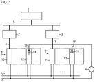
- Fig. 1 shows a section of a process control system with a guide 1 in a process control level, a first and second control computer 2, 3 in the form of programmable logic controllers in a control level and an actuator 4 at the field level.
- the field level contains further, not shown here field devices that detect the states of a technical process in the form of sensors and designed as actuators affect the process targeted.
- the guide device 1 and the control computers 2, 3 are connected to each other via a system bus 5 (eg, Ethernet).
- the two control computers 2, 3 operate one and the same control or user program in redundant operation, wherein they process input values of sensors obtained, inter alia, via separate digital field buses 6, 7 (eg PROFIBUS DP) ,
- the connection of the field devices to the field buses 6, 7 of the two control computers 2, 3 is carried out by a first and a second decentralized peripheral station 8, 9.
- Each of the two peripheral stations 8, 9 consists of an interface module (head assembly) 10, 11 for connection to the respective field bus 6, 7 and a number of single or multi-channel peripheral modules, of which only one output module 12, 13 is shown here.
- the Actuator 4 is connected via decoupling diodes 14, 15 to the signal outputs 16, 17 of the two output modules 12, 13.
- the interface modules 10, 11 transfer output values, which they receive from the respective control computer 2, 3 for the actuator 4, to the output modules 12, 13, wherein the diodes 14, 15 for the actuator 4 disjunctively (OR) link digital values and analog values Add (streams). Both output modules 12, 13 are active. You will both receive the same output values in error-free redundancy mode.
- the two control computers 2, 3 equalize themselves accordingly. Alternatively, only one of the two modules, for. B. 12, active and passes the output values received from the control computer 2 to the actuator. 4
- the interface modules 10, 11 each monitor the fieldbus 6, 7 to which they are connected, and in the event of a fault, for example in the event of a failure of the control computer (eg STOP, cable, etc.), output to all the output modules of the respective one Peripheral 8, 9 a command to output replacement values, for example in the form of the last received output values.
- the control computer eg STOP, cable, etc.
- Fig. 2 shows an example of the inventive arrangement with two redundant modules 21, 22, which are the two output modules 12, 13 from Fig. 1 or any other type of assembly.
- Both modules that is to say the first module 21 and the second module 22, have the same structure and each contain a functional unit 23, 24 for carrying out module-specific functions in the context of which input data 25 is received and output data 26 are generated.
- the first module 21 contains a current source 27 (or alternatively a voltage source), which is connected via a series connection of a first controllable switch 28 and a first current sensor 29 to a first line connection 30.
- the assembly 21 further includes a second current sensor 31 connected in series with a second controllable switch 32 between a second conduit port 33 and ground lies.
- the controllable switches 28, 32 and the current sensors 29, 31 each consist of an optocoupler with light emitting diode and phototransistor.
- the functional unit 23 In working order, d. H. when the assembly 21 is plugged in, powered on and has not shut itself off due to an error, the functional unit 23 generates a control signal 34, with which the controllable switches 28, 32 are closed. In the functional state, the module 21 can be active but also passive in the sense that it currently performs no module-specific functions, but can be activated to do so.
- the two current sensors 29, 31 are provided to detect a current flowing via the first or second line connection 30, 33 and report this to a monitoring device 35, which then generates a monitoring signal 36 for the functional unit 23, if at least one of the two current sensors 29, 31 detects a current flow.
- the redundant second assembly 22 also includes a first controllable switch 37 and a first current sensor 38 between a current source 39 (or voltage source) and a first lead terminal 40 and a second current sensor 41 in series with a second controllable switch 42 between a second lead terminal 43 and ground , Again, there are the controllable switches 37, 42 and the current sensors 38, 41 of optocouplers.
- the functional unit 24 In the functional state of the second module 22, the functional unit 24 generates a control signal 44 with which the controllable switches 37, 42 are closed.
- the two current sensors 38, 41 report a current flow occurring via the first or second line connection 40, 43 to a monitoring device 45 which then generates a monitoring signal 46 for the functional unit 24 if at least one of the two current sensors 38, 41 has such a current flow reports.
- the first line connection 30 of the first assembly 21 is connected via a first line 47 to the second line connection 43 of the second assembly 22.
- a second conduit 48 connects the first conduit port 40 of the second assembly 22 to the second conduit port 33 of the first assembly 21.
- the first current sensor 29 in the first assembly 21 and the second current sensor 41 in the second assembly 22 therefore detect a possible current flow on the first assembly Line 47, while first current sensor 38 in the second assembly 22 and the second current sensor 31 in the first assembly 21 detect a current flow on the second line 48.
- the controllable switches 28, 32 are closed and both current sensors 29, 31 are active in order to be able to detect a current flow on each of the two lines 47, 48.
- the other assembly 22 is also in a functional state, its controllable switches 37, 42 are also closed, so that a current flows in both lines 47, 48.
- the current sensors 29, 31 in the first module 21 and the current sensors 38, 41 in the second module 22 then detect a current flow on both lines 47, 48, so that the respective downstream monitoring devices 35 and 45, a respective other module 22 and Produce 21 as functional characterizing monitoring signal 36 and 46, respectively. Even if one of the two lines, z. B.
- the first module 21 includes a transmitting device 49 for connecting an information signal 50 generated by the functional unit 23 to the first line 47 and a receiving device 51 for receiving an information signal 52 received via the second line 48 from the second module 22.
- the transmitting device 49 and receiving devices 51 are controlled by the functional unit 23.
- a receiving device 53 receives the information signal 50 obtained via the first line 47 from the first subassembly 21 while a transmitting device 54 applies the information signal 52 to the second line 48.
- connection of the information signals 50, 52 takes place on the lines 47, 48 by pulse modulation of the current supplied by the respective current sources 27, 39, to which the controllable switches 28, 37 (or alternatively the switches 32, 42) are used, which are thus part of the respective transmitting device.
- the detection of the pulse modulation of the current and thus the reception of the information signals is carried out by the current sensors 31, 41, which are therefore part of the respective receiving device.
- optocoupler other components such. As electromechanical switches or semiconductor switches or current measuring resistors for the controllable switch and / or current sensors are used.
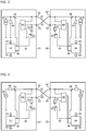
- Fig. 3 shows an alternative example of the inventive arrangement in which the first power source 27 in the first assembly 21 and the second power source 30 in the second assembly 22 are each connected to ground via a first and second flow divider.
- the first current divider has a first resistor 60 and a second resistor 61, wherein the first resistor 60 together with a first controllable switch 62 in the first assembly 21 and the second resistor 31 in series with a second controllable switch 63 in the second assembly 22nd is arranged.
- the in the different Assemblies 21, 22 arranged resistors 60, 61 of the first flow divider are connected to each other via the first line 47.
- the first controllable switch 62 is located between the first line 47 and the first current source 27 and the first resistor 60 parallel to it.
- the second current divider connected to the second current source 39 also has a first resistor 64 and a second resistor 65, wherein the first resistor 64, together with a first controllable switch 66 in the second assembly 22 and the second resistor 65 in series with a second controllable Switch 67 is disposed in the first assembly 21.
- the arranged in the different modules 21, 22 resistors 64, 65 of the second flow divider are connected to each other via the second line 48.
- the first controllable switch 66 is located between the second line 48 and the second current source 39 and the first resistor 64 parallel to it.
- the respective first resistor 60, 64 of the two current dividers carries the current of the current source 27 and 39, respectively, when the first switch 62 or 66 is open.
- the first resistor 60, 64 is dimensioned such that the voltage drop across it does not exceed a maximum value.
- the first resistor 60, 64 can be formed by the internal resistance of the relevant current source.
- the controllable switches 62, 63, 66, 67 are controlled by means of the control signals 34, 44 generated by the functional units 23, 24 in such a way that the switches 62 and 67 in the first module 21 are closed when this module 21 is functional, and the switches 66 and 63 in the second assembly 22 are closed when this assembly 22 is functional.
- the controllable switches 62, 63, 66, 67 it may be z.
- semiconductor switches such as transistors or MOSFETs, optocouplers or electromechanical switch (relay switch) act.
- a monitoring device 68 or 69 is connected to the two lines 47, 48, which detects the voltages between each of these lines 47, 48 and ground and the respective other module as a functionally identifying monitoring signal 36, 46th generated when at least one of the two detected voltages has a value which corresponds to the expected at closed switches 62, 63, 66, 67 at the second resistors 61, 65 voltage drop.
- information 50, 52 to be exchanged between the assemblies 21, 22 can be transmitted and received by pulse modulation of the currents flowing in the lines 47, 48.
- the mean value of the current on the lines 47, 48 can be used for the mutual monitoring of the assemblies 21, 22 and is not disturbed by the modulation component used for the information transmission.
- the information can be retrieved in different ways, e.g. B. inductively, be modulated onto the currents in the lines 47, 48 and received in the same way.
- Fig. 4 shows a further example of the two redundant modules 21, 22, which differs from the Fig. 3 differs in that instead of current sources, a first and second voltage source 70, 71 in the different modules 21, 22 is present.
- the resistors 60, 61 form a first voltage divider, via which the first voltage source 70 is connected to ground.
- the resistors 64, 65 form a second voltage divider, via which the second voltage source 71 is connected to ground.
- the voltage sources 70, 71 each supply a voltage U. If both assemblies 21, 22 are functional, all the switches 62, 63, 66, 67 are closed and both monitoring devices 68, 69 detect on the two lines 47, 48 each have a voltage U / 2. This indicates for each of the two monitoring devices 68, 69 that the respective other module is functional.
- the monitoring device 68 in the first module 21 measures the voltage U / 2 on the line 47 and the value zero on the line 48.
- the monitoring device 69 in the second module 21 measures at the Line 48, the voltage U and on the line 47, the voltage U / 2. Since at least one of the monitoring device 41 and at least one of the monitoring device 42 detected voltages is U / 2, both monitoring devices 68, 69 despite breakage of the line 48 determines the operability of the other opposing module.
- Fig. 5 finally shows an example of a configuration of the current source 27 or 39 as a switchable constant current source, so that the first switch 28, 37 (FIG. Fig. 2 ) or 62, 66 ( Fig. 3 ) can be omitted in the relevant assembly 21, 22.
Landscapes
- Physics & Mathematics (AREA)
- General Physics & Mathematics (AREA)
- Engineering & Computer Science (AREA)
- Automation & Control Theory (AREA)
- Safety Devices In Control Systems (AREA)
Description
Prozessleitsysteme wie z. B. SIMATIC PCS 7 von Siemens dienen zur Automatisierung von Prozessen in technischen Anlagen und sind üblicherweise hierarchisch durch mehrere Ebenen strukturiert. Auf der Feldebene werden mittels Feldgeräten die Zustände des technischen Prozesses erfasst (Sensoren) bzw. der Prozess gezielt beeinflusst (Aktoren). In der Steuerungsebene führen Steuerrechner (speicherprogrammierbare Steuerungen mit CPU-Einheiten) feldnahe Steuerungs- und Regelungsfunktionen aus, wobei sie Eingabewerte von den Sensoren, z. B. einem Druckmessumformer, empfangen und Ausgabewerte an die Aktoren, z. B. einen Stellungsregler für ein Regelventil, abgeben. Auf der Prozessführungsebene findet in Leitrechnern die übergeordnete Steuerung und Regelung des Prozesses statt.Process control systems such. For example, SIMATIC PCS 7 from Siemens are used to automate processes in technical plants and are usually structured hierarchically through several levels. At the field level, the states of the technical process (sensors) or the process are specifically influenced (actuators) by means of field devices. At the control level, control computers (programmable logic controllers with CPU units) perform field-level control functions, taking input values from the sensors, e.g. As a pressure transmitter, received and output values to the actuators, eg. B. a positioner for a control valve deliver. At the process control level, the master control and regulation of the process takes place in master computers.
Der Datenaustausch zwischen den Feldgeräten und den Steuerrechnern erfolgt üblicherweise über einen digitalen Feldbus, wie z. B. PROFIBUS DP oder PROFINET. Da die Feldgeräte normalerweise selbst keinen entsprechenden Feldbusanschluss aufweisen, werden sie über dezentrale Peripheriestationen an den Feldbus angebunden. Eine Peripheriestation besteht aus einem Interfacemodul (Kopfbaugruppe) zum Anschluss an den Feldbus und einer Anzahl von Peripheriebaugruppen (digitale und analoge Ein- und Ausgabebaugruppen) zum Anschluss der Feldgeräte. Die Peripheriebaugruppen können einen oder mehrere Kanäle aufweisen, an denen jeweils ein Feldgerät angeschlossen werden kann.The data exchange between the field devices and the control computers usually takes place via a digital field bus, such. PROFIBUS DP or PROFINET. Since the field devices do not normally have a corresponding fieldbus connection, they are connected to the fieldbus via decentralized peripheral stations. A peripheral station consists of an interface module (head module) for connection to the fieldbus and a number of I / O modules (digital and analog input and output modules) for connecting the field devices. The peripheral modules can have one or more channels, to each of which a field device can be connected.
So offenbart die
Zur wahlweise redundanten oder nichtredundanten Erfassung von Messwerten eines Zweileiter-Messumformers enthält jede der beiden Baugruppen eine Strom- oder Spannungsquelle, die über eine Reihenschaltung aus einem ersten steuerbaren Schalter und einem ersten Stromsensor mit einem ersten Leitungsanschluss der jeweiligen Baugruppe verbunden ist. Beide Baugruppen weisen ferner jeweils einen zweiten Leitungsanschluss und einen Masseanschluss auf, zwischen denen ein zweiter Stromsensor in Reihe mit einem zweiten steuerbaren Schalter liegt. Die beiden Baugruppen sind an ihren ersten Leitungsanschlüssen über eine erste Leitung und an ihren zweiten Leitungsanschlüssen über eine zweite Leitung miteinander verbunden, wobei der Zweileiter-Messumformer zwischen beide Leitungen geschaltet ist. Je nach Schaltstellung der steuerbaren Schalter sind zwei redundante und zwei nichtredundante Betriebsarten möglich. In den redundanten Betriebsarten ist der erste Schalter in einer der beiden Baugruppen und der zweite Schalter in der jeweils anderen Baugruppe geschlossen, wobei der Messstrom des Messumformers mittels des ersten Stromsensors in der einen Baugruppe und des zweiten Stromsensors in der anderen Baugruppe redundant erfasst wird. In den nichtredundanten Betriebsarten sind der erste und zweite Schalter in nur einer der beiden Baugruppen geschlossen, wobei der Messstrom entweder von dem ersten oder dem zweiten Stromsensor in der betreffenden Baugruppe erfasst wird.For selectively redundant or non-redundant detection of measured values of a two-wire transmitter, each of the two modules contains a current or voltage source which is connected via a series connection of a first controllable switch and a first current sensor to a first line connection of the respective module. Both modules furthermore each have a second line connection and a ground connection, between which a second current sensor is connected in series with a second controllable switch. The two modules are connected to each other at their first line terminals via a first line and at their second line terminals via a second line, wherein the two-wire transmitter is connected between the two lines. Depending on the switching position of the controllable switches, two redundant and two non-redundant operating modes are possible. In the redundant modes, the first switch in one of the two modules and the second switch in the other module is closed, wherein the measuring current of the transmitter by means of the first current sensor in one assembly and the second current sensor in the other assembly is detected redundantly. In the non-redundant modes, the first and second switches in only one of the two assemblies are closed, with the sense current detected by either the first or the second current sensor in the particular assembly.
Eine gegenseitige Überwachung beider Peripheriebaugruppen ist in der
Für einen ordnungsgemäßen und sicheren Redundanzbetrieb zweier Baugruppen, beispielsweise zweier Peripheriebaugruppen, ist es erforderlich, dass jede der Baugruppen über die Funktionsfähigkeit der anderen Baugruppe informiert ist, um beispielsweise ein Umschalten von einer aktiven Baugruppe auf eine nicht vorhandene oder nicht funktionsfähige Baugruppe zu verhindern.For a proper and safe redundancy operation of two modules, for example, two peripheral modules, it is necessary that each of the modules on the functionality the other module is informed, for example, to prevent switching from an active module to a non-existent or non-functional module.
Der Erfindung liegt daher die Aufgabe zugrunde eine gegenseitige Überwachung von zwei redundanten Baugruppen mit geringem schaltungstechnischem Aufwand zu ermöglichen, wobei die Überwachung selbst ebenfalls redundant erfolgen soll.The invention is therefore based on the object to allow mutual monitoring of two redundant modules with low circuit complexity, the monitoring itself should also be done redundantly.
Gemäß der Erfindung wird die Aufgabe gelöst durch eine Anordnung mit einer ersten Baugruppe und einer redundanten zweiten Baugruppe, die einander gegenseitig überwachen, wozu
- jede der beiden Baugruppen eine Strom- oder Spannungsquelle enthält, die entweder ein- und ausschaltbar ausgebildet und über einen ersten Stromsensor mit einem ersten Leitungsanschluss der jeweiligen Baugruppe verbunden ist oder über eine Reihenschaltung aus einem ersten steuerbaren Schalter und dem ersten Stromsensor mit dem ersten Leitungsanschluss verbunden ist,
- jede der beiden Baugruppen ferner jeweils über einen zweiten Leitungsanschluss und einen Masseanschluss verfügt, zwischen denen ein zweiter Stromsensor in Reihe mit einem zweiten steuerbaren Schalter liegt,
- der erste Leitungsanschluss der ersten Baugruppe über eine erste Leitung mit dem zweiten Leitungsanschluss der zweiten Baugruppe und der erste Leitungsanschluss der zweiten Baugruppe über eine zweite Leitung mit dem zweiten Leitungsanschluss der ersten Baugruppe verbunden ist,
- jede der beiden Baugruppen dazu ausgebildet ist, im funktionsfähigen Zustand ihre Strom- oder Spannungsquelle einzuschalten und den in ihr enthaltenen zweiten steuerbaren Schalter zu schließen oder beide der in ihr enthaltenen steuerbaren Schalter zu schließen, und
- jede der beiden Baugruppen eine an den beiden in ihr enthaltenen Stromsensoren und angeschlossene Überwachungseinrichtung enthält, die ein die jeweils andere Baugruppe als funktionsfähig identifizierendes Überwachungssignal erzeugt, wenn mindestens einer der beiden Stromsensoren einen Stromfluss detektiert.
- each of the two modules contains a current or voltage source which is either switched on and off and connected via a first current sensor to a first line terminal of the respective module or connected via a series circuit of a first controllable switch and the first current sensor to the first line terminal is
- each of the two assemblies further each having a second lead terminal and a ground terminal, between which a second current sensor is in series with a second controllable switch,
- the first line connection of the first module is connected to the second line connection of the second module via a first line and the first line connection of the second module is connected to the second line connection of the first module via a second line
- each of the two modules is adapted to turn on their power or voltage source in the functional state and to close the second controllable switch contained in it or to close both of the controllable switch contained in it, and
- each of the two assemblies includes one of the two current sensors contained therein and connected monitoring means which generates a monitoring signal identifying the respective other assembly as being operable, if at least one of the two current sensors detects a current flow.
Die Leitungsanschlüsse und Leitungen der vorstehend definierten Anordnung dienen nur zum Zwecke der gegenseitigen Überwachung beider Baugruppen und nicht zum Anschluss eines Aktors oder Messumformers. Wenn also an den beiden Baugruppen der erfindungsgemäßen Anordnung ein Aktor oder Messumformer, beispielsweise in der aus der
Eine Baugruppe ist in einem funktionsfähigen Zustand, wenn sie gesteckt ist, mit Strom versorgt wird und sich nicht aufgrund eines Fehlers selbst abgeschaltet hat. Die funktionsfähige Baugruppe kann aktiv aber auch in dem Sinne passiv sein, dass sie aktuell keine baugruppenspezifischen Funktionen ausführt, aber dazu aktiviert werden kann. In der erfindungsgemäßen Anordnung sind bei einer funktionsfähigen Baugruppe die steuerbaren Schalter geschlossen und beide Stromsensoren aktiv, um auf jeder der beiden Leitungen einen Stromfluss detektieren zu können. Wenn sich die andere Baugruppe ebenfalls in einem funktionsfähigen Zustand befindend, sind auch ihre steuerbaren Schalter geschlossen, so dass in beiden Leitungen ein Strom fließt. Jede der beiden Baugruppen detektiert dann einen Stromfluss in beiden Leitungen und so die Funktionsfähigkeit der jeweils anderen Baugruppen. Wenn eine der beiden Leitungen unterbrochen ist, wird von beiden Baugruppen immer noch ein Stromfluss in der anderen Leitung und so die Funktionsfähigkeit der jeweils anderen Baugruppe detektiert. Wenn dagegen eine der beiden Baugruppen funktionsunfähig ist, sind ihre steuerbaren Schalter geöffnet, so dass in keiner der beiden Leitungen ein Strom fließt und so die andere Baugruppe die Funktionsunfähigkeit der einen Baugruppe erkennt.An assembly is in a working condition when plugged in, powered on and not shut down due to an error. The functional module can be active but also passive in the sense that it currently performs no module-specific functions, but can be activated to do so. In the arrangement according to the invention, the controllable switches are closed in a functional assembly and both current sensors are active in order to detect a current flow on each of the two lines. When the other assembly is also in a functional state, its controllable switches are also closed, so that a current flows in both lines. Each of the two modules then detects a current flow in both lines and thus the functionality of each other modules. If one of the two lines is interrupted, a current flow in the other line and thus the functionality of the other module is still detected by both modules. If, on the other hand, one of the two modules is inoperable, its controllable switches are opened, so that no current flows in either of the two lines, and thus the other module recognizes the inoperability of the one module.
Da für die gegenseitige Überwachung beider Baugruppen nur detektiert werden muss, ob ein Strom fließt oder kein Strom fließt, können die Stromsensoren jeweils als Optokoppler mit einem Lichtsender (z. B. Leuchtdiode) und Lichtempfänger (z. B. Fotodiode oder Fototransistor) ausgebildet sein. Dies hat neben einem besonders geringen schaltungstechnischen Aufwand auch den Vorteil, dass aufgrund der galvanischen Trennung die Ausgangsignale der Stromsensoren unmittelbar und potentialfrei an die Überwachungseinrichtung übergeben werden.Since for the mutual monitoring of both modules only has to be detected, whether a current flows or no current flows, the current sensors can each as an optocoupler with a light emitter (eg LED) and light receiver (eg photodiode or phototransistor). This has in addition to a particularly low circuit complexity and the advantage that due to the galvanic isolation, the output signals of the current sensors are passed directly and potential-free to the monitoring device.
Alternativ kann der Stromfluss anhand eines Spannungsabfalls über einem Strommesswiderstand detektiert werden. Wenn in jeder der beiden Baugruppen ein solcher Strommesswiderstand mit einem seiner Anschlüsse unmittelbar mit dem zweiten Leitungsanschluss der betreffenden Baugruppe verbunden ist und die von dort zu der anderen Baugruppe führende Leitung intakt ist, kann ein Spannungsabfall über diesem Strommesswiderstand gleichzeitig in beiden Baugruppen detektiert werden. In diesem Fall teilen sich der erste Stromsensor in der einen Baugruppe und der zweite Stromsensor in der anderen Baugruppe einen gemeinsamen Strommesswiderstand in der anderen Baugruppe, was den schaltungstechnischen Aufwand für die Detektion des Stromflusses verringert.Alternatively, the current flow can be detected based on a voltage drop across a current sense resistor. If, in each of the two modules, such a current measuring resistor is connected with one of its terminals directly to the second line terminal of the relevant module and the line leading from there to the other module is intact, a voltage drop across this current measuring resistor can be detected simultaneously in both modules. In this case, the first current sensor in the one module and the second current sensor in the other module share a common current measuring resistor in the other module, which reduces the circuitry complexity for the detection of the current flow.
Bei den steuerbaren Schaltern kann es sich um Halbleiterschalter, wie z. B. Transistorschalter, oder Optokoppler handeln, wobei auch hier die Optokoppler den Vorteil einer potentialfreien Ansteuerung haben; d. h., obwohl der erste und zweite steuerbare Schalter einer Baugruppe in unterschiedlichen Stromkreisen liegen, können sie mit ein und demselben Steuersignal angesteuert werden. Wenn die Strom- oder Spannungsquelle in der jeweiligen Baugruppe ein- und ausschaltbar ist, beispielsweise im Falle einer schaltbaren Konstantstromquelle, kann der erste Schalter in der betreffenden Baugruppe entfallen.The controllable switches may be semiconductor switches, such. B. transistor switch, or optocouplers act, and here the optocouplers have the advantage of a potential-free control; d. h., Although the first and second controllable switch of a module in different circuits, they can be controlled with one and the same control signal. If the current or voltage source in the respective module is switched on and off, for example in the case of a switchable constant current source, the first switch can be omitted in the relevant module.
In einer Ausgestaltung der Erfindung kann eine oder können beide Leitungen dazu genutzt werden, um für den Redundanzbetrieb nützliche Informationen auszutauschen, wozu mindestens eine der beiden Baugruppen eine Sendeeinrichtung zum Aufschalten eines, z. B. mittelwertfreien, Informationssignals auf mindestens eine der beiden Leitungen aufweist und die andere Baugruppe eine Empfangseinrichtung zum Empfang des Informationssignals enthält. Bei den Informationen kann es sich beispielsweise um einen für beide Baugruppen gültigen Steuerbefehl handeln, den die aktive Baugruppe von dem aktiven Steuerrechner erhält und an die inaktive Baugruppe weitergibt. Ersatzwerte werden anstelle von Ein- oder Ausgabewerten verwendet, wenn diese nicht vorliegen, ungültig oder unzuverlässig sind. Bei dem Ersatzwert kann es sich zum Beispiel um den von der Baugruppe zuletzt erhaltenen Ausgabewert, aber auch um einen anderen, von den betriebsmäßigen Ausgabewerten unterscheidbaren parametrierbaren Wert handeln, um z. B: einen Fehler zu melden oder den Aktor (z. B. ein Ventil) in eine sichere Position zu steuern. Indem das aufgeschaltete InformationssignalIn one embodiment of the invention, one or both lines can be used to exchange useful information for the redundant operation, including at least one of the two modules a transmitting device for connecting a, z. B. has mean value, information signal on at least one of the two lines and the other Assembly includes a receiving device for receiving the information signal. The information may, for example, be a valid control command for both modules, which the active module receives from the active control computer and forwards it to the inactive module. Substitute values are used instead of input or output values if they are not present, invalid, or unreliable. The substitute value can be, for example, the output value last received by the assembly, but also another parameterizable value that can be differentiated from the operational output values, in order, for. B: Report an error or control the actuator (eg a valve) to a safe position. By the switched information signal
Die Informationsübertragung von der einen Baugruppe zur anderen kann beispielsweise durch Pulsmodulation des Stromes auf einer der Leitungen erfolgen, wozu in vorteilhafter Weise der im Stromweg der betreffenden Leitung liegende steuerbare Schalter in der einen Baugruppe verwendet und von der Sendeeinrichtung mit einem bestimmten Puls-Pausen-Verhältnis oder Pulsbreitenverhältnis ein- und ausgeschaltet werden kann. Der im Stromweg der betreffenden Leitung liegende Stromsensor der anderen Baugruppe kann als funktioneller Bestandteil der Empfangseinrichtung dazu genutzt werden, den pulsmodulierten Strom zu detektieren. Auch hier erweist sich die Verwendung von Optokopplern als besonders vorteilhaft, weil dies eine potentialfreie Ansteuerung des steuerbaren Schalters bzw. eine potentialfreie Detektion des pulsmodulierten Stromes ermöglicht.The information transfer from one module to the other can be done, for example, by pulse modulation of the current on one of the lines, including used in the current path of the relevant line controllable switch in an assembly used by the transmitter and with a certain pulse-pause ratio in an advantageous manner or pulse width ratio can be switched on and off. The lying in the current path of the relevant line current sensor of the other module can be used as a functional part of the receiving device to detect the pulse-modulated current. Again, the use of optocouplers proves to be particularly advantageous because this allows a potential-free control of the controllable switch or a potential-free detection of the pulse-modulated current.
Zur weiteren Erläuterung der Erfindung wird im Folgenden auf die Figuren der Zeichnung Bezug genommen; im Einzelnen zeigen:
- Fig. 1
- in schematischer Blockdarstellung ein redundantes Steuersystem mit zwei redundanten Baugruppen,
- Fig. 2
- ein erstes Ausführungsbeispiel der erfindungsgemäßen Anordnung mit zwei Baugruppen, in denen Optokoppler als Schalter und Stromsensoren dienen,
- Fig. 3
- ein zweites Ausführungsbeispiel der erfindungsgemäßen Anordnung mit Stromquellen und Strommesswiderständen in den Baugruppen,
- Fig. 4
- ein weiteres Ausführungsbeispiel der erfindungsgemäßen Anordnung mit Spannungsquellen und Strommesswiderständen in den Baugruppen und
- Fig. 5
- ein Beispiel für eine schaltbare Stromquelle.
- Fig. 1
- a schematic block diagram of a redundant control system with two redundant modules,
- Fig. 2
- A first embodiment of the arrangement according to the invention with two modules in which opto-couplers serve as switches and current sensors,
- Fig. 3
- A second embodiment of the arrangement according to the invention with current sources and current measuring resistors in the assemblies,
- Fig. 4
- a further embodiment of the inventive arrangement with voltage sources and current measuring resistors in the modules and
- Fig. 5
- an example of a switchable power source.
Gleiche und funktionsgleiche Elemente mit sind mit gleichen Bezugszeichen versehen.Same and functionally identical elements are provided with the same reference numerals.
Die Interfacemodule 10, 11 überwachen jeweils den Feldbus 6, 7, an den sie angeschlossen sind, und geben im Falle einer Störung, beispielsweise bei Ausfall des Steuerrechners (z. B. Betriebszustand STOPP, Kabel gezogen, usw.) an alle Ausgabebaugruppen der betreffenden Peripheriestation 8, 9 einen Befehl zur Ausgabe von Ersatzwerten, beispielsweise in Form der zuletzt erhaltenen Ausgabewerte.The
Die erste Baugruppe 21 enthält eine Stromquelle 27 (oder alternativ eine Spannungsquelle), die über eine Reihenschaltung aus einem ersten steuerbaren Schalter 28 und einem ersten Stromsensor 29 mit einem ersten Leitungsanschluss 30 verbunden ist. Die Baugruppe 21 enthält ferner einen zweiten Stromsensor 31, der in Reihe mit einem zweiten steuerbaren Schalter 32 zwischen einem zweiten Leitungsanschluss 33 und Masse liegt. Bei dem gezeigten Ausführungsbeispiel bestehen die steuerbaren Schalter 28, 32 und die Stromsensoren 29, 31 jeweils aus einem Optokoppler mit Leuchtdiode und Fototransistor.The
Im funktionsfähigen Zustand, d. h. wenn die Baugruppe 21 gesteckt ist, mit Strom versorgt wird und sich nicht aufgrund eines Fehlers selbst abgeschaltet hat, erzeugt die Funktionseinheit 23 ein Steuersignal 34, mit dem die steuerbaren Schalter 28, 32 geschlossen werden. Im funktionsfähigen Zustand kann die Baugruppe 21 aktiv aber auch in dem Sinne passiv sein, dass sie aktuell keine baugruppenspezifische Funktionen ausführt, aber dazu aktiviert werden kann.In working order, d. H. when the
Die beiden Stromsensoren 29, 31 sind dazu vorgesehen, einen über den ersten bzw. zweiten Leitungsanschluss 30, 33 fließenden Strom zu detektieren und dies einer Überwachungseinrichtung 35 zu melden, die dann ein Überwachungssignal 36 für die Funktionseinheit 23 erzeugt, wenn mindestens einer der beiden Stromsensoren 29, 31 einen Stromfluss detektiert.The two
Die redundante zweite Baugruppe 22 enthält ebenfalls einen ersten steuerbaren Schalter 37 und einen ersten Stromsensor 38 zwischen einer Stromquelle 39 (oder Spannungsquelle) und einem ersten Leitungsanschluss 40 sowie einen zweiten Stromsensor 41 in Reihe mit einem zweiten steuerbaren Schalter 42 zwischen einem zweiten Leitungsanschluss 43 und Masse. Auch hier bestehen die steuerbaren Schalter 37, 42 und die Stromsensoren 38, 41 aus Optokopplern.The redundant
Im funktionsfähigen Zustand der zweiten Baugruppe 22 erzeugt die Funktionseinheit 24 ein Steuersignal 44, mit dem die steuerbaren Schalter 37, 42 geschlossen werden. Die beiden Stromsensoren 38, 41 melden einen über den ersten bzw. zweiten Leitungsanschluss 40, 43 stattfindenden Stromfluss an eine Überwachungseinrichtung 45 zu melden, die dann ein Überwachungssignal 46 für die Funktionseinheit 24 erzeugt, wenn mindestens einer der beiden Stromsensoren 38, 41 einen solchen Stromfluss meldet.In the functional state of the
Der erste Leitungsanschluss 30 der ersten Baugruppe 21 ist über eine erste Leitung 47 mit dem zweiten Leitungsanschluss 43 der zweiten Baugruppe 22 verbunden. Eine zweite Leitung 48 verbindet den ersten Leitungsanschluss 40 der zweiten Baugruppe 22 mit dem zweiten Leitungsanschluss 33 der ersten Baugruppe 21. Der erste Stromsensor 29 in der ersten Baugruppe 21 und der zweite Stromsensor 41 in der zweiten Baugruppe 22 detektieren daher einen möglichen Stromfluss auf der ersten Leitung 47, während erste Stromsensor 38 in der zweiten Baugruppe 22 und der zweite Stromsensor 31 in der ersten Baugruppe 21 einen Stromfluss auf der zweiten Leitung 48 detektieren.The
Bei Funktionsfähigkeit der ersten Baugruppe 21 sind die steuerbaren Schalter 28, 32 geschlossen und beide Stromsensoren 29, 31 aktiv, um auf jeder der beiden Leitungen 47, 48 einen Stromfluss detektieren zu können. Wenn sich die andere Baugruppe 22 ebenfalls in einem funktionsfähigen Zustand befindend, sind auch ihre steuerbaren Schalter 37,42 geschlossen, so dass in beiden Leitungen 47, 48 ein Strom fließt. Die Stromsensoren 29, 31 in der ersten Baugruppe 21 und die Stromsensoren 38, 41 in der zweiten Baugruppen 22 detektieren dann auf beiden Leitungen 47, 48 einen Stromfluss, so dass die jeweils nachgeordneten Überwachungseinrichtungen 35 bzw. 45 ein die jeweils andere Baugruppe 22 bzw. 21 als funktionsfähig kennzeichnendes Überwachungssignal 36 bzw. 46 erzeugen. Selbst wenn eine der beiden Leitungen, z. B. 47, unterbrochen ist, wird von beiden Baugruppen 21, 22 immer noch ein Stromfluss in der anderen Leitung 48 und so die Funktionsfähigkeit der jeweils anderen Baugruppe detektiert. Wenn dagegen beispielsweise die Baugruppe 22 nicht gesteckt ist oder funktionsuntüchtig ist, sind ihre steuerbaren Schalter 37, 42 geöffnet, so dass in keiner der beiden Leitungen 47, 48 ein Strom fließt und die erste Baugruppe 21 die Funktionsunfähigkeit der zweiten Baugruppe 22 daran erkennt, dass keiner der Stromsensoren 29, 31 einen Stromfluss detektiert.When the
Um für den Redundanzbetrieb nützliche Informationen auszutauschen, enthält die erste Baugruppe 21 eine Sendeeinrichtung 49 zum Aufschalten eines von der Funktionseinheit 23 erzeugten Informationssignals 50 auf die erste Leitung 47 und eine Empfangseinrichtung 51 zum Empfang eines über die zweite Leitung 48 von der zweiten Baugruppe 22 erhaltenen Informationssignals 52. enthält. Die Sendeeinrichtung 49 und Empfangseinrichtungen 51 werden von der Funktionseinheit 23 gesteuert. In der baugleichen zweiten Baugruppe 22 empfängt eine Empfangseinrichtung 53 das über die erste Leitung 47 von der ersten Baugruppe 21 erhaltene Informationssignal 50 während eine Sendeeinrichtung 54 das Informationssignal 52 auf die zweite Leitung 48 aufschaltet.In order to exchange useful information for the redundant operation, the
Bei dem gezeigten Ausführungsbeispiel erfolgt die Aufschaltung der Informationssignale 50, 52 auf die Leitungen 47, 48 durch Pulsmodulation des von den jeweiligen Stromquellen 27, 39 gelieferten Stromes, wozu die steuerbaren Schalter 28, 37 (oder alternativ die Schalter 32, 42) genutzt werden, welche somit Bestandteil der jeweiligen Sendeeinrichtung sind. Die Detektion der Pulsmodulation des Stromes und somit der Empfang der Informationssignale erfolgt durch die Stromsensoren 31, 41, welche daher Bestandteil der jeweiligen Empfangseinrichtung sind.In the embodiment shown, the connection of the information signals 50, 52 takes place on the
Wie im Folgenden erläutert, können anstelle der in
Der mit der zweiten Stromquelle 39 verbundene zweite Stromteiler weist ebenfalls einen ersten Widerstand 64 und einen zweiten Widerstand 65 auf, wobei der erste Widerstand 64 zusammen mit einem ersten steuerbaren Schalter 66 in der zweiten Baugruppe 22 und der zweite Widerstand 65 in Reihe mit einen zweiten steuerbaren Schalter 67 in der ersten Baugruppe 21 angeordnet ist. Die in den unterschiedlichen Baugruppen 21, 22 angeordneten Widerstände 64, 65 des zweiten Stromteilers sind über die zweite Leitung 48 miteinander verbunden. Der erste steuerbare Schalter 66 liegt zwischen der zweiten Leitung 48 und der zweiten Stromquelle 39 bzw. dem zu ihr parallelen ersten Widerstand 64.The second current divider connected to the second
Der jeweils erste Widerstand 60, 64 der beiden Stromteiler führt den Strom der Stromquelle 27 bzw. 39, wenn der erste Schalter 62 bzw. 66 geöffnet ist. Dabei ist der erste Widerstand 60, 64 so bemessen, dass der Spannungsabfall an ihm einen Maximalwert nicht übersteigt. Bei realen Stromquellen 27, 39 mit Strombegrenzung kann der erste Widerstand 60, 64 von dem Innenwiderstand der betreffenden Stromquelle gebildet werden.The respective
Die steuerbaren Schalter 62, 63, 66, 67 werden mittels der von den Funktionseinheiten 23, 24 erzeugten Steuersignale 34, 44 in der Weise angesteuert, dass die Schalter 62 und 67 in der ersten Baugruppe 21 geschlossen werden, wenn diese Baugruppe 21 funktionsfähig ist, und die Schalter 66 und 63 in der zweiten Baugruppe 22 geschlossen werden, wenn diese Baugruppe 22 funktionsfähig ist. Bei den steuerbaren Schaltern 62, 63, 66, 67 kann es sich z. B. um Halbleiterschalter, wie Transistoren oder MOSFETs, Optokoppler oder elektromechanische Schalter (Relaisschalter) handeln.The controllable switches 62, 63, 66, 67 are controlled by means of the control signals 34, 44 generated by the
In jeder der beiden Baugruppen 21, 22 ist eine Überwachungseinrichtung 68 bzw. 69 an den beiden Leitungen 47, 48 angeschlossen, die die Spannungen zwischen jeder dieser Leitungen 47, 48 und Masse erfasst und ein die jeweils andere Baugruppe als funktionsfähig identifizierendes Überwachungssignal 36, 46 erzeugt, wenn mindestens eine der beiden erfassten Spannungen einen Wert aufweist, der dem bei geschlossenen Schaltern 62, 63, 66, 67 an den zweiten Widerständen 61, 65 zu erwartenden Spannungsabfall entspricht.In each of the two
Angenommen, alle Widerstände 60, 61, 64, 65 sind gleich groß und haben der Wert R. Die Stromquellen 27, 39 liefern jeweils einen Strom I. Wenn beide Baugruppen 21, 22 funktionsfähig sind, sind alle Schalter 62, 63, 66, 67 geschlossen und beide Überwachungseinrichtungen 68, 69 erfassen an der beiden Leitungen 47, 48 jeweils eine Spannung U = I/2·R. Dies zeigt für jede der beiden Überwachungseinrichtungen 68, 69 an, dass die andere Baugruppe funktionsfähig ist.Assuming that all the
Wenn jetzt z. B. die Leitung 48 bricht, findet kein Stromfluss durch den Widerstand 65 statt so dass der Strom I der Stromquelle 39 ausschließlich durch den Widerstand 64 fließt und einen Spannungsabfall U = I·R erzeugt. Die Überwachungseinrichtung 68 in der ersten Baugruppe 21 misst an der Leitung 47 die Spannung U = I/2·R und an der Leitung 48 den Wert Null. Die Überwachungseinrichtung 69 in der zweiten Baugruppe 22 misst an der Leitung 48 die Spannung U = I·R und an der Leitung 47 die Spannung U = I/2·R. Da mindestens eine der von der Überwachungseinrichtung 68 und mindestens eine der von der Überwachungseinrichtung 69 erfassten Spannungen U = I/2·R beträgt, stellen beide Überwachungseinrichtungen 68, 69 trotz Bruchs der Leitung 48 die Funktionsfähigkeit der anderen gegenüberliegenden Baugruppe fest.If now z. B. breaks the
Wenn bei intakten Leitungen 47, 48 die zweite Baugruppe 22 funktionsunfähig ist, sind deren Schalter 63, 66 geöffnet. Die Schalter 62, 67 der funktionierenden ersten Baugruppe 21 sind geschlossen. Die erste Überwachungseinrichtung 68 misst an der Leitung 47 die Spannung U = I·R und an der Leitung 48 den Wert Null. Da beide erfassten Spannungen von U = I/2·R verschieden sind, erkennt die Überwachungseinrichtung 68 so den Ausfall oder das Nichtvorhandensein der anderen gegenüberliegenden Baugruppe 22.If
Wie im Beispiel nach
Angenommen, alle Widerstände 60, 61, 64, 65 sind gleich groß und haben der Wert R. Die Spannungsquellen 70, 71 liefern jeweils eine Spannung U. Wenn beide Baugruppen 21, 22 funktionsfähig sind, sind alle Schalter 62, 63, 66, 67 geschlossen und beide Überwachungseinrichtungen 68, 69 erfassen an der beiden Leitungen 47, 48 jeweils eine Spannung U/2. Dies zeigt für jede der beiden Überwachungseinrichtungen 68, 69 an, dass die jeweils andere Baugruppe funktionsfähig ist. Im Falle einer Unterbrechung der Leitung 48 misst die Überwachungseinrichtung 68 in der ersten Baugruppe 21 an der Leitung 47 die Spannung U/2 und an der Leitung 48 den Wert Null. Die Überwachungseinrichtung 69 in der zweiten Baugruppe 21 misst an der Leitung 48 die Spannung U und an der Leitung 47 die Spannung U/2. Da mindestens eine der von der Überwachungseinrichtung 41 und mindestens eine der von der Überwachungseinrichtung 42 erfassten Spannungen U/2 beträgt, stellen beide Überwachungseinrichtungen 68, 69 trotz Bruchs der Leitung 48 die Funktionsfähigkeit der jeweils anderen gegenüberliegenden Baugruppe fest.Assuming that all the
Claims (8)
- Arrangement having a first module (21) and a redundant, second module (22), which monitor one another mutually, for which purpose:- each of the two modules (21, 22) contains a current source or voltage source (27, 39), which either is designed to be capable of being switched on and off and is connected via a first current sensor (29, 38) to a first line terminal (30, 40) of the module concerned, or is connected to the first line terminal (30, 40) via a series circuit composed of a first controllable switch (28, 37) and the first current sensor (29, 38);- each of the two modules (21, 22) also has a second line terminal (33, 43) and a ground terminal, between which lies a second current sensor (31, 41) in series with a second controllable switch (32, 42);- the first line terminal (30) of the first module (21) is connected via a first line (47) to the second line terminal (43) of the second module (22), and the first line terminal (40) of the second module (22) is connected via a second line (48) to the second line terminal (33) of the first module (21);- each of the two modules (21, 22) is designed, when in the functioning state, to switch on its current source or voltage source (27, 39) and to close the second controllable switch (32, 42) contained in said module or to close both of the controllable switches (28, 32, 37, 42) contained in said module; and- each of the two modules (21, 22) contains a monitoring device (35, 45) connected to the two current sensors contained (29, 31, 38, 41) in said module, which monitoring device generates a monitoring signal (36, 46) identifying the corresponding other module as functioning if at least one of the two current sensors (29, 31, 38, 41) detects a current flow.
- Arrangement according to claim 1, characterised in that the current sensors (29, 31, 38, 41) are each embodied as optocouplers.
- Arrangement according to claim 1, characterised in that the current sensors each comprise a current sensing resistor (61, 65), and the monitoring device (68, 69) is designed to detect a voltage drop across the current sensing resistor (61, 65).
- Arrangement according to claim 3, characterised in that the first current sensor in the one module (21) and the second current sensor in the corresponding other module (22) have a common current sensing resistor (61, 65) in the corresponding other module, which resistor is connected at one end to the second line terminal (43, 33) of the corresponding other module.
- Arrangement according to one of the preceding claims, characterised in that the controllable switches (28, 32, 37, 42) are each embodied as optocouplers.
- Arrangement according to one of the preceding claims, characterised in that at least one of the two modules (21, 22) comprises a transmitter (49, 54) for applying an information signal (50, 52) to at least one of the two lines (47, 48), and in that the corresponding other module contains a receiver (51, 53) for receiving the information signal (50, 52).
- Arrangement according to claim 6, characterised in that in the at least one of the two modules (21, 22), one of the controllable switches (28, 37) located there is part of the transmitter (49, 50), and in that the transmitter (49, 50) is designed for pulse modulation by the controllable switch (28, 37) of a current supplied by the current source or voltage source (27, 39).
- Arrangement according to claim 7, characterised in that in the corresponding other module, one of the current sensors (31, 41) located there is part of the receiver (51, 53) in order to receive the pulse-modulated current.
Priority Applications (3)
| Application Number | Priority Date | Filing Date | Title |
|---|---|---|---|
| EP16205179.1A EP3336624B1 (en) | 2016-12-19 | 2016-12-19 | Arrangement with two redundant boards which monitor each other |
| US15/845,921 US10379144B2 (en) | 2016-12-19 | 2017-12-18 | Arrangement having two redundant modules |
| CN201711370525.4A CN108205258B (en) | 2016-12-19 | 2017-12-18 | Device with two redundant components |
Applications Claiming Priority (1)
| Application Number | Priority Date | Filing Date | Title |
|---|---|---|---|
| EP16205179.1A EP3336624B1 (en) | 2016-12-19 | 2016-12-19 | Arrangement with two redundant boards which monitor each other |
Publications (2)
| Publication Number | Publication Date |
|---|---|
| EP3336624A1 EP3336624A1 (en) | 2018-06-20 |
| EP3336624B1 true EP3336624B1 (en) | 2019-02-06 |
Family
ID=57570741
Family Applications (1)
| Application Number | Title | Priority Date | Filing Date |
|---|---|---|---|
| EP16205179.1A Active EP3336624B1 (en) | 2016-12-19 | 2016-12-19 | Arrangement with two redundant boards which monitor each other |
Country Status (3)
| Country | Link |
|---|---|
| US (1) | US10379144B2 (en) |
| EP (1) | EP3336624B1 (en) |
| CN (1) | CN108205258B (en) |
Families Citing this family (4)
| Publication number | Priority date | Publication date | Assignee | Title |
|---|---|---|---|---|
| DE102018200120A1 (en) * | 2018-01-05 | 2019-07-11 | Kuka Deutschland Gmbh | Safety control with at least one semiconductor switching contact |
| US11169505B2 (en) | 2019-03-20 | 2021-11-09 | Rockwell Automation Technologies, Inc. | Constant input resistance for redundant input modules employed in high availability systems |
| US11848408B2 (en) * | 2019-12-02 | 2023-12-19 | Boe Technology Group Co., Ltd. | Drive circuit substrate, LED display panel and method of forming the same, and display device |
| WO2023058189A1 (en) * | 2021-10-07 | 2023-04-13 | 日立Astemo株式会社 | Communication semiconductor device |
Family Cites Families (30)
| Publication number | Priority date | Publication date | Assignee | Title |
|---|---|---|---|---|
| US3979720A (en) * | 1974-05-22 | 1976-09-07 | Siemens Aktiengesellschaft | Apparatus for monitoring a redundant multi-channel analog system |
| AU6894491A (en) * | 1989-11-27 | 1991-06-26 | Olin Corporation | Method and apparatus for providing backup process control |
| SE466172B (en) * | 1990-05-15 | 1992-01-07 | Asea Brown Boveri | DEVICE FOR THE PREPARATION OF A VARIOUS CURRENT RESPONSIBLE FOR A DEVICE APPLIED |
| US6161202A (en) * | 1997-02-18 | 2000-12-12 | Ee-Signals Gmbh & Co. Kg | Method for the monitoring of integrated circuits |
| DE10304968B4 (en) * | 2003-02-06 | 2005-02-17 | Endress + Hauser Gmbh + Co. Kg | Device for determining and / or monitoring a process variable of a medium |
| GB2404100A (en) * | 2003-07-17 | 2005-01-19 | Bombardier Transp | Model-based monitoring an operation of a converter |
| DE102004034451A1 (en) | 2004-07-16 | 2006-02-16 | Siemens Ag | Redundant control system for computer peripheral has actuator connected between pair of diodes connected to measuring circuits and pair of switches in parallel |
| DE102005036777B4 (en) * | 2005-08-02 | 2020-01-09 | Phoenix Contact Gmbh & Co. Kg | Three-phase power amplifier |
| JP5194808B2 (en) * | 2008-01-09 | 2013-05-08 | 日本電気株式会社 | Redundant power supply system, power supply control device, power supply control method, and program |
| JP4702403B2 (en) * | 2008-06-06 | 2011-06-15 | ミツミ電機株式会社 | Semiconductor integrated circuit for charge control |
| DE102008027113A1 (en) * | 2008-06-06 | 2009-12-10 | Siemens Aktiengesellschaft | Method and device for controlling a motor |
| EP2166365A1 (en) * | 2008-09-19 | 2010-03-24 | Bombardier Transportation GmbH | Distributed safety monitoring system provided with a safety loop and method of testing such a system |
| CN101814716A (en) * | 2010-03-31 | 2010-08-25 | 银川英奥特自控有限公司 | Current signal detecting switch and valve control and fault protection device |
| EP2378380B1 (en) * | 2010-04-16 | 2012-12-12 | Siemens Aktiengesellschaft | Connection device for field devices and method for operating same |
| CN102082463B (en) * | 2011-01-26 | 2012-11-28 | 江阴众和电力仪表有限公司 | Method for realizing redundancy of 4-20-mA current output in distributed control system (DCS) and circuit |
| JP5854188B2 (en) * | 2011-06-02 | 2016-02-09 | 横河電機株式会社 | I/O module and duplex system using same |
| DE102012101516A1 (en) * | 2012-02-24 | 2013-08-29 | Pilz Gmbh & Co. Kg | Safety switching device with power supply |
| CN104049572B (en) * | 2012-08-14 | 2019-04-23 | 费希尔控制国际公司 | Control signal protection equipment |
| DE102013100159A1 (en) * | 2012-11-28 | 2014-05-28 | Endress + Hauser Gmbh + Co. Kg | Field device for determining or monitoring a process variable in automation technology |
| DE102013204510A1 (en) * | 2013-03-15 | 2014-09-18 | Robert Bosch Gmbh | Electrically intrinsically safe battery module with ultrafast discharge circuit and method for monitoring a battery module |
| DE102013107904A1 (en) * | 2013-07-24 | 2015-01-29 | Endress + Hauser Flowtec Ag | Measuring device with switchable measuring and operating electronics for the transmission of a measuring signal |
| US20150045936A1 (en) * | 2013-08-08 | 2015-02-12 | General Electric Company | System and method for modular controller assembly supporting redundant configurations |
| CN104345201A (en) * | 2013-08-09 | 2015-02-11 | 华为技术有限公司 | Leakage current detection method and device |
| JP5719040B1 (en) * | 2013-08-20 | 2015-05-13 | 株式会社小松製作所 | Controller for construction machinery |
| JP5904189B2 (en) * | 2013-10-29 | 2016-04-13 | 横河電機株式会社 | Signal processing device |
| DE102013226763A1 (en) * | 2013-12-19 | 2015-06-25 | Bayerische Motoren Werke Aktiengesellschaft | Safety circuit arrangement for an electric drive unit |
| KR101769664B1 (en) * | 2015-03-10 | 2017-08-18 | 엘에스산전 주식회사 | Redundant controller of hvdc system |
| CN104767276B (en) * | 2015-04-18 | 2017-08-15 | 漳州科华技术有限责任公司 | A kind of redundancy accessory power supply control system and its control method |
| KR20160141573A (en) * | 2015-06-01 | 2016-12-09 | 엘에스산전 주식회사 | Realy failure dectection apparatus of redundancy system |
| CN105067864B (en) * | 2015-07-23 | 2018-03-30 | 北京天航华创科技股份有限公司 | A kind of double remaining energy handover management strategies of stratospheric airship |
-
2016
- 2016-12-19 EP EP16205179.1A patent/EP3336624B1/en active Active
-
2017
- 2017-12-18 CN CN201711370525.4A patent/CN108205258B/en active Active
- 2017-12-18 US US15/845,921 patent/US10379144B2/en active Active
Non-Patent Citations (1)
| Title |
|---|
| None * |
Also Published As
| Publication number | Publication date |
|---|---|
| EP3336624A1 (en) | 2018-06-20 |
| US10379144B2 (en) | 2019-08-13 |
| CN108205258B (en) | 2021-05-07 |
| CN108205258A (en) | 2018-06-26 |
| US20180172740A1 (en) | 2018-06-21 |
Similar Documents
| Publication | Publication Date | Title |
|---|---|---|
| DE102009042368B4 (en) | Control system for controlling safety-critical processes | |
| EP1860513B1 (en) | Connection for secure transmission of an analogue signal value | |
| EP1927914B1 (en) | Safety module and automation system | |
| EP2171549B1 (en) | Safety apparatus for the multichannel control of a safety device | |
| EP3336624B1 (en) | Arrangement with two redundant boards which monitor each other | |
| DE102008036967A1 (en) | Universal interface for a wireless adapter | |
| EP2586051A1 (en) | Safety circuit arrangement for the fail-safe connection or disconnection of a hazardous installation | |
| EP2649496A1 (en) | Safety switching device for the failsafe shutdown of an electrical consumer | |
| DE4416795A1 (en) | Redundant-configurable data transfer system for programmable controller in industrial process | |
| EP3214512A1 (en) | Redundant control system for an actuator and method for its redundant control | |
| EP4288842A1 (en) | Field device and functional unit for such a field device | |
| EP2926203B1 (en) | Field device for determining or monitoring a process variable in automation engineering | |
| WO2013110296A1 (en) | Device for the intrinsically safe supply, control and/or evaluation of field devices in the explosion-proof area | |
| EP3200033B1 (en) | Assembly comprising at least two peripheral units with a sensor | |
| EP1672446B1 (en) | Secure Input/Ouput assembly for a controller | |
| EP1695159B1 (en) | Redundant control system | |
| EP2767877B1 (en) | Control and data transmission system for transmission of safety-related data via a field bus | |
| EP3133447A1 (en) | Safety switch | |
| EP1619565B1 (en) | Method and apparatus for safe switching of a bus- based automation system | |
| DE102010038459A1 (en) | Safety system, has safety module comprising system interface for direct contacting and communication with group protection unit, and load branch comprising another system interface for direct communication with safety module | |
| EP3834388B1 (en) | Line driver device for data flow control | |
| DE102004034451A1 (en) | Redundant control system for computer peripheral has actuator connected between pair of diodes connected to measuring circuits and pair of switches in parallel | |
| DE102019003206B3 (en) | Safety order | |
| DE102019004530B4 (en) | Efficient line driver device for data flow control | |
| DE19754769A1 (en) | Secure multi-channel data communications field bus system for positioning element in factory or railway automation |
Legal Events
| Date | Code | Title | Description |
|---|---|---|---|
| PUAI | Public reference made under article 153(3) epc to a published international application that has entered the european phase |
Free format text: ORIGINAL CODE: 0009012 |
|
| STAA | Information on the status of an ep patent application or granted ep patent |
Free format text: STATUS: THE APPLICATION HAS BEEN PUBLISHED |
|
| STAA | Information on the status of an ep patent application or granted ep patent |
Free format text: STATUS: REQUEST FOR EXAMINATION WAS MADE |
|
| AK | Designated contracting states |
Kind code of ref document: A1 Designated state(s): AL AT BE BG CH CY CZ DE DK EE ES FI FR GB GR HR HU IE IS IT LI LT LU LV MC MK MT NL NO PL PT RO RS SE SI SK SM TR |
|
| AX | Request for extension of the european patent |
Extension state: BA ME |
|
| 17P | Request for examination filed |
Effective date: 20180605 |
|
| RBV | Designated contracting states (corrected) |
Designated state(s): AL AT BE BG CH CY CZ DE DK EE ES FI FR GB GR HR HU IE IS IT LI LT LU LV MC MK MT NL NO PL PT RO RS SE SI SK SM TR |
|
| GRAP | Despatch of communication of intention to grant a patent |
Free format text: ORIGINAL CODE: EPIDOSNIGR1 |
|
| STAA | Information on the status of an ep patent application or granted ep patent |
Free format text: STATUS: GRANT OF PATENT IS INTENDED |
|
| RIC1 | Information provided on ipc code assigned before grant |
Ipc: G05B 19/042 20060101AFI20180924BHEP Ipc: G05B 9/03 20060101ALI20180924BHEP |
|
| INTG | Intention to grant announced |
Effective date: 20181015 |
|
| GRAS | Grant fee paid |
Free format text: ORIGINAL CODE: EPIDOSNIGR3 |
|
| GRAA | (expected) grant |
Free format text: ORIGINAL CODE: 0009210 |
|
| STAA | Information on the status of an ep patent application or granted ep patent |
Free format text: STATUS: THE PATENT HAS BEEN GRANTED |
|
| AK | Designated contracting states |
Kind code of ref document: B1 Designated state(s): AL AT BE BG CH CY CZ DE DK EE ES FI FR GB GR HR HU IE IS IT LI LT LU LV MC MK MT NL NO PL PT RO RS SE SI SK SM TR |
|
| REG | Reference to a national code |
Ref country code: GB Ref legal event code: FG4D Free format text: NOT ENGLISH |
|
| REG | Reference to a national code |
Ref country code: CH Ref legal event code: EP Ref country code: AT Ref legal event code: REF Ref document number: 1095300 Country of ref document: AT Kind code of ref document: T Effective date: 20190215 |
|
| REG | Reference to a national code |
Ref country code: IE Ref legal event code: FG4D Free format text: LANGUAGE OF EP DOCUMENT: GERMAN |
|
| REG | Reference to a national code |
Ref country code: DE Ref legal event code: R096 Ref document number: 502016003353 Country of ref document: DE |
|
| REG | Reference to a national code |
Ref country code: NL Ref legal event code: MP Effective date: 20190206 |
|
| REG | Reference to a national code |
Ref country code: LT Ref legal event code: MG4D |
|
| PG25 | Lapsed in a contracting state [announced via postgrant information from national office to epo] |
Ref country code: PT Free format text: LAPSE BECAUSE OF FAILURE TO SUBMIT A TRANSLATION OF THE DESCRIPTION OR TO PAY THE FEE WITHIN THE PRESCRIBED TIME-LIMIT Effective date: 20190606 Ref country code: SE Free format text: LAPSE BECAUSE OF FAILURE TO SUBMIT A TRANSLATION OF THE DESCRIPTION OR TO PAY THE FEE WITHIN THE PRESCRIBED TIME-LIMIT Effective date: 20190206 Ref country code: NL Free format text: LAPSE BECAUSE OF FAILURE TO SUBMIT A TRANSLATION OF THE DESCRIPTION OR TO PAY THE FEE WITHIN THE PRESCRIBED TIME-LIMIT Effective date: 20190206 Ref country code: LT Free format text: LAPSE BECAUSE OF FAILURE TO SUBMIT A TRANSLATION OF THE DESCRIPTION OR TO PAY THE FEE WITHIN THE PRESCRIBED TIME-LIMIT Effective date: 20190206 Ref country code: NO Free format text: LAPSE BECAUSE OF FAILURE TO SUBMIT A TRANSLATION OF THE DESCRIPTION OR TO PAY THE FEE WITHIN THE PRESCRIBED TIME-LIMIT Effective date: 20190506 Ref country code: FI Free format text: LAPSE BECAUSE OF FAILURE TO SUBMIT A TRANSLATION OF THE DESCRIPTION OR TO PAY THE FEE WITHIN THE PRESCRIBED TIME-LIMIT Effective date: 20190206 |
|
| PG25 | Lapsed in a contracting state [announced via postgrant information from national office to epo] |
Ref country code: GR Free format text: LAPSE BECAUSE OF FAILURE TO SUBMIT A TRANSLATION OF THE DESCRIPTION OR TO PAY THE FEE WITHIN THE PRESCRIBED TIME-LIMIT Effective date: 20190507 Ref country code: IS Free format text: LAPSE BECAUSE OF FAILURE TO SUBMIT A TRANSLATION OF THE DESCRIPTION OR TO PAY THE FEE WITHIN THE PRESCRIBED TIME-LIMIT Effective date: 20190606 Ref country code: RS Free format text: LAPSE BECAUSE OF FAILURE TO SUBMIT A TRANSLATION OF THE DESCRIPTION OR TO PAY THE FEE WITHIN THE PRESCRIBED TIME-LIMIT Effective date: 20190206 Ref country code: BG Free format text: LAPSE BECAUSE OF FAILURE TO SUBMIT A TRANSLATION OF THE DESCRIPTION OR TO PAY THE FEE WITHIN THE PRESCRIBED TIME-LIMIT Effective date: 20190506 Ref country code: LV Free format text: LAPSE BECAUSE OF FAILURE TO SUBMIT A TRANSLATION OF THE DESCRIPTION OR TO PAY THE FEE WITHIN THE PRESCRIBED TIME-LIMIT Effective date: 20190206 Ref country code: HR Free format text: LAPSE BECAUSE OF FAILURE TO SUBMIT A TRANSLATION OF THE DESCRIPTION OR TO PAY THE FEE WITHIN THE PRESCRIBED TIME-LIMIT Effective date: 20190206 |
|
| PG25 | Lapsed in a contracting state [announced via postgrant information from national office to epo] |
Ref country code: RO Free format text: LAPSE BECAUSE OF FAILURE TO SUBMIT A TRANSLATION OF THE DESCRIPTION OR TO PAY THE FEE WITHIN THE PRESCRIBED TIME-LIMIT Effective date: 20190206 Ref country code: CZ Free format text: LAPSE BECAUSE OF FAILURE TO SUBMIT A TRANSLATION OF THE DESCRIPTION OR TO PAY THE FEE WITHIN THE PRESCRIBED TIME-LIMIT Effective date: 20190206 Ref country code: AL Free format text: LAPSE BECAUSE OF FAILURE TO SUBMIT A TRANSLATION OF THE DESCRIPTION OR TO PAY THE FEE WITHIN THE PRESCRIBED TIME-LIMIT Effective date: 20190206 Ref country code: SK Free format text: LAPSE BECAUSE OF FAILURE TO SUBMIT A TRANSLATION OF THE DESCRIPTION OR TO PAY THE FEE WITHIN THE PRESCRIBED TIME-LIMIT Effective date: 20190206 Ref country code: ES Free format text: LAPSE BECAUSE OF FAILURE TO SUBMIT A TRANSLATION OF THE DESCRIPTION OR TO PAY THE FEE WITHIN THE PRESCRIBED TIME-LIMIT Effective date: 20190206 Ref country code: DK Free format text: LAPSE BECAUSE OF FAILURE TO SUBMIT A TRANSLATION OF THE DESCRIPTION OR TO PAY THE FEE WITHIN THE PRESCRIBED TIME-LIMIT Effective date: 20190206 Ref country code: EE Free format text: LAPSE BECAUSE OF FAILURE TO SUBMIT A TRANSLATION OF THE DESCRIPTION OR TO PAY THE FEE WITHIN THE PRESCRIBED TIME-LIMIT Effective date: 20190206 |
|
| REG | Reference to a national code |
Ref country code: DE Ref legal event code: R097 Ref document number: 502016003353 Country of ref document: DE |
|
| PG25 | Lapsed in a contracting state [announced via postgrant information from national office to epo] |
Ref country code: SM Free format text: LAPSE BECAUSE OF FAILURE TO SUBMIT A TRANSLATION OF THE DESCRIPTION OR TO PAY THE FEE WITHIN THE PRESCRIBED TIME-LIMIT Effective date: 20190206 Ref country code: PL Free format text: LAPSE BECAUSE OF FAILURE TO SUBMIT A TRANSLATION OF THE DESCRIPTION OR TO PAY THE FEE WITHIN THE PRESCRIBED TIME-LIMIT Effective date: 20190206 |
|
| PLBE | No opposition filed within time limit |
Free format text: ORIGINAL CODE: 0009261 |
|
| STAA | Information on the status of an ep patent application or granted ep patent |
Free format text: STATUS: NO OPPOSITION FILED WITHIN TIME LIMIT |
|
| 26N | No opposition filed |
Effective date: 20191107 |
|
| PG25 | Lapsed in a contracting state [announced via postgrant information from national office to epo] |
Ref country code: TR Free format text: LAPSE BECAUSE OF FAILURE TO SUBMIT A TRANSLATION OF THE DESCRIPTION OR TO PAY THE FEE WITHIN THE PRESCRIBED TIME-LIMIT Effective date: 20190206 |
|
| REG | Reference to a national code |
Ref country code: CH Ref legal event code: PL |
|
| REG | Reference to a national code |
Ref country code: BE Ref legal event code: MM Effective date: 20191231 |
|
| PG25 | Lapsed in a contracting state [announced via postgrant information from national office to epo] |
Ref country code: MC Free format text: LAPSE BECAUSE OF FAILURE TO SUBMIT A TRANSLATION OF THE DESCRIPTION OR TO PAY THE FEE WITHIN THE PRESCRIBED TIME-LIMIT Effective date: 20190206 |
|
| PG25 | Lapsed in a contracting state [announced via postgrant information from national office to epo] |
Ref country code: LU Free format text: LAPSE BECAUSE OF NON-PAYMENT OF DUE FEES Effective date: 20191219 Ref country code: IE Free format text: LAPSE BECAUSE OF NON-PAYMENT OF DUE FEES Effective date: 20191219 |
|
| PG25 | Lapsed in a contracting state [announced via postgrant information from national office to epo] |
Ref country code: BE Free format text: LAPSE BECAUSE OF NON-PAYMENT OF DUE FEES Effective date: 20191231 Ref country code: CH Free format text: LAPSE BECAUSE OF NON-PAYMENT OF DUE FEES Effective date: 20191231 Ref country code: LI Free format text: LAPSE BECAUSE OF NON-PAYMENT OF DUE FEES Effective date: 20191231 |
|
| PG25 | Lapsed in a contracting state [announced via postgrant information from national office to epo] |
Ref country code: CY Free format text: LAPSE BECAUSE OF FAILURE TO SUBMIT A TRANSLATION OF THE DESCRIPTION OR TO PAY THE FEE WITHIN THE PRESCRIBED TIME-LIMIT Effective date: 20190206 |
|
| PG25 | Lapsed in a contracting state [announced via postgrant information from national office to epo] |
Ref country code: HU Free format text: LAPSE BECAUSE OF FAILURE TO SUBMIT A TRANSLATION OF THE DESCRIPTION OR TO PAY THE FEE WITHIN THE PRESCRIBED TIME-LIMIT; INVALID AB INITIO Effective date: 20161219 Ref country code: MT Free format text: LAPSE BECAUSE OF FAILURE TO SUBMIT A TRANSLATION OF THE DESCRIPTION OR TO PAY THE FEE WITHIN THE PRESCRIBED TIME-LIMIT Effective date: 20190206 |
|
| PG25 | Lapsed in a contracting state [announced via postgrant information from national office to epo] |
Ref country code: SI Free format text: LAPSE BECAUSE OF FAILURE TO SUBMIT A TRANSLATION OF THE DESCRIPTION OR TO PAY THE FEE WITHIN THE PRESCRIBED TIME-LIMIT Effective date: 20190206 |
|
| PG25 | Lapsed in a contracting state [announced via postgrant information from national office to epo] |
Ref country code: MK Free format text: LAPSE BECAUSE OF FAILURE TO SUBMIT A TRANSLATION OF THE DESCRIPTION OR TO PAY THE FEE WITHIN THE PRESCRIBED TIME-LIMIT Effective date: 20190206 |
|
| REG | Reference to a national code |
Ref country code: AT Ref legal event code: MM01 Ref document number: 1095300 Country of ref document: AT Kind code of ref document: T Effective date: 20211219 |
|
| PG25 | Lapsed in a contracting state [announced via postgrant information from national office to epo] |
Ref country code: AT Free format text: LAPSE BECAUSE OF NON-PAYMENT OF DUE FEES Effective date: 20211219 |
|
| PGFP | Annual fee paid to national office [announced via postgrant information from national office to epo] |
Ref country code: DE Payment date: 20250220 Year of fee payment: 9 |
|
| PGFP | Annual fee paid to national office [announced via postgrant information from national office to epo] |
Ref country code: GB Payment date: 20250115 Year of fee payment: 9 |
|
| PGFP | Annual fee paid to national office [announced via postgrant information from national office to epo] |
Ref country code: IT Payment date: 20251219 Year of fee payment: 10 |
|
| PGFP | Annual fee paid to national office [announced via postgrant information from national office to epo] |
Ref country code: FR Payment date: 20251215 Year of fee payment: 10 |