EP2926203B1 - Field device for determining or monitoring a process variable in automation engineering - Google Patents
Field device for determining or monitoring a process variable in automation engineering Download PDFInfo
- Publication number
- EP2926203B1 EP2926203B1 EP13783587.2A EP13783587A EP2926203B1 EP 2926203 B1 EP2926203 B1 EP 2926203B1 EP 13783587 A EP13783587 A EP 13783587A EP 2926203 B1 EP2926203 B1 EP 2926203B1
- Authority
- EP
- European Patent Office
- Prior art keywords
- channel
- current
- channels
- field device
- voter
- Prior art date
- Legal status (The legal status is an assumption and is not a legal conclusion. Google has not performed a legal analysis and makes no representation as to the accuracy of the status listed.)
- Active
Links
- 238000000034 method Methods 0.000 title claims description 18
- 238000012544 monitoring process Methods 0.000 title claims description 10
- 238000001514 detection method Methods 0.000 claims description 28
- 230000007257 malfunction Effects 0.000 claims description 27
- 238000011156 evaluation Methods 0.000 claims description 12
- 238000005516 engineering process Methods 0.000 claims description 10
- 238000013461 design Methods 0.000 claims description 3
- 230000000694 effects Effects 0.000 claims description 3
- 230000003068 static effect Effects 0.000 claims description 2
- 238000005259 measurement Methods 0.000 description 25
- 230000009977 dual effect Effects 0.000 description 5
- 238000004891 communication Methods 0.000 description 3
- 239000007788 liquid Substances 0.000 description 3
- 238000010586 diagram Methods 0.000 description 2
- 230000001960 triggered effect Effects 0.000 description 2
- 102100039435 C-X-C motif chemokine 17 Human genes 0.000 description 1
- 101000889048 Homo sapiens C-X-C motif chemokine 17 Proteins 0.000 description 1
- 238000004364 calculation method Methods 0.000 description 1
- 238000001311 chemical methods and process Methods 0.000 description 1
- 238000011161 development Methods 0.000 description 1
- 239000002360 explosive Substances 0.000 description 1
- 238000004801 process automation Methods 0.000 description 1
- 238000004886 process control Methods 0.000 description 1
- 239000000126 substance Substances 0.000 description 1
- 230000009897 systematic effect Effects 0.000 description 1
- 230000007704 transition Effects 0.000 description 1
- 238000011144 upstream manufacturing Methods 0.000 description 1
- 238000012800 visualization Methods 0.000 description 1
Images


Classifications
-
- G—PHYSICS
- G05—CONTROLLING; REGULATING
- G05B—CONTROL OR REGULATING SYSTEMS IN GENERAL; FUNCTIONAL ELEMENTS OF SUCH SYSTEMS; MONITORING OR TESTING ARRANGEMENTS FOR SUCH SYSTEMS OR ELEMENTS
- G05B9/00—Safety arrangements
- G05B9/02—Safety arrangements electric
- G05B9/03—Safety arrangements electric with multiple-channel loop, i.e. redundant control systems
-
- G—PHYSICS
- G05—CONTROLLING; REGULATING
- G05B—CONTROL OR REGULATING SYSTEMS IN GENERAL; FUNCTIONAL ELEMENTS OF SUCH SYSTEMS; MONITORING OR TESTING ARRANGEMENTS FOR SUCH SYSTEMS OR ELEMENTS
- G05B9/00—Safety arrangements
- G05B9/02—Safety arrangements electric
Definitions
- the invention relates to a field device for determining or monitoring a process variable in automation technology.
- the field device is designed so that it meets a safety standard that is required in a given safety-critical application.
- the field device comprises a sensor, which operates according to a defined measurement principle, and a control / evaluation unit, which processes and evaluates the measurement data supplied by the sensor along at least three redundant and / or diversely designed measurement channels.
- a suitable solution is from the WO 2004/013585 A1 known.
- field devices are used which are used to determine and monitor process variables.
- field devices are level gauges, flowmeters, analyzers, pressure and temperature measuring devices, humidity and conductivity meters, density and viscosity meters.
- the sensors of these field devices detect the corresponding process variables, e.g. level, flow, pH, substance concentration, pressure, temperature, humidity, conductivity, density or viscosity.
- field devices in modern automation systems are connected via communication networks, such as HART multidrop, point-to-point connection, Profibus, Foundation Fieldbus, to a superordinated unit, which is referred to as a control system or control room.
- This higher-level unit is used for process control, process visualization, process monitoring and commissioning and for operating the field devices.
- Additional components necessary for the operation of fieldbus systems which are directly connected to a fieldbus and which in particular serve for communication with the higher-level units, are also frequently referred to as field devices. These additional components are, for. For example, remote I / Os, gateways, linking devices, controllers or wireless adapters.
- the field devices must meet a wide variety of security requirements.
- the field devices In order to meet the respective security requirements, e.g. IEC61508 (SIL standard 'Safety Integrity Level'), the field devices must be redundant and / or diversified.
- Redundancy means increased safety through double or multiple design of all safety-related hardware and software components.
- Diversity means that the hardware components located in the different measurement channels, e.g. a microprocessor, from different manufacturers and / or that they are of different types.
- software components diversity requires that the software stored in the microprocessors come from different sources, ie from different manufacturers or programmers. All these measures are intended to ensure that a safety-critical failure of the field device as well as the occurrence of simultaneously occurring systematic errors in the provision of the measured value is excluded with a high degree of probability.
- An example of a safety-relevant application is the level monitoring in a tank in which a flammable or a non-flammable, but water-polluting liquid is stored.
- a flammable or a non-flammable, but water-polluting liquid is stored.
- it must be ensured that the supply of liquid to the tank is interrupted immediately as soon as a maximum permissible level is reached. This, in turn, requires that the meter reliably detects the level and operates without errors.
- the measuring channel is designed to be redundant and / or diverse, however, the voter, usually a microprocessor, represents the Achilles heel of a field device which should meet high and highest safety requirements.
- the microprocessor is designed monolithic. If a dangerous fault occurs (according to the nomenclature of the aforementioned standard), the field device fails. In order to meet the requirements of SIL 3, the proportion of dangerous faults to the number of all possible faults may not exceed one per cent. With a conventional microprocessor, this level of security can not be achieved.
- the publication DE102009026785 A1 relates to a field device for determining and / or monitoring a physical or chemical process variable, consisting of a sensor which operates in accordance with a predetermined measurement principle, and a control evaluation unit, the measured data / measured values supplied by the sensor depending on one in the respective safety critical Application requested safety standard along a predetermined number of redundant or diversified or redundant and diversified measuring paths processed and / or evaluated.
- the invention has for its object to provide a field device, which is characterized by increased functional safety.
- the object is achieved by a field device for determining or monitoring a process variable in automation technology according to claim 1.
- each Stromeinstellkanal a Stromeinstelliser and a current control wherein the Stromeinstelliser and the current control are connected in parallel.
- the voter consists of several components that are at least partially or completely designed twice redundant.
- the voter be a majority voter having a plurality of voter channels, wherein the following components are found in each voter channel: a comparator stage through which the output signals provided by the individual current setting channels are compared with each other, an error detection stage provided by appropriately linking the voters Output signals of the comparator stages associated with the voter channels detects a malfunction occurring in a measurement channel or in a current setting channel, and a turn-off stage which turns off the current setting channel in which the error detection stage detects a malfunction.
- each Voterkanal comprises part of the comparator stage, part of the error detection unit and part of the Ausschaltcut, and that each Voterkanal is designed as an integrated part of the associated measurement channel and the associated Stromeinstellkanals.
- the comparator stage for each Voterkanal comprises two comparator modules, which compares the output signals of the associated Stromeinstellkanals with the output signals of the remaining Stromeinstellkanäle.
- each of the error detection stages is a logic stage constructed of two NAND gates, the output signals of the comparators of a first Voter channel being associated with a selected measurement channel at the inputs of the first NAND gate, and at the second NAND Gate applied to the inputs of the first NAND gate redundant outputs of the comparators of the second Voterkanals and the third Voterkanals, and wherein the outputs of the first NAND gate and the second NAND gate constitute the control signals for the downstream Ausschaltcut.
- Each measuring channel or each current setting channel is preferably assigned its own power supply. This embodiment has the advantage that when one of the power supplies fails, no total failure of the field device occurs.
- an alarm current module which is designed such that it sets a fault current, eg of 22 mA, if a malfunction occurs simultaneously in at least two measurement channels or in two current adjustment channels. This prevents the current interface from becoming unstable.
- control / evaluation unit with measuring channels or current setting channels is at least partially designed as a reconfigurable logic module with a plurality of partially dynamically reconfigurable functional modules in the measuring channels or in the current setting channels.
- the reconfiguration controller is assigned at least one microprocessor which partially dynamically reconfigures the functional modules of a measurement channel or of a current adjustment channel in which an error is detected.
- At least one of the measurement channels and / or the current adjustment channels is configured analog-based in an FPAA.
- the individual measuring channels or Stromeinstellkanäle are spaced apart so that a temperature and / or a voltage change in a measuring channel or Stromeinstellkanal have / have no effect on an adjacent measuring channel or Stromeinstellkanal.
- the at least one microprocessor is permanently configured in a static region of the logic device.
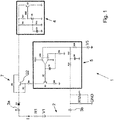
- Fig. 1 shows a block diagram of a well-known from the prior art analog current output module 1.
- the current output module 1 sets the current I on a current loop 2 and a two-wire line.
- the field device or here the meter consisting of sensor S and a control / evaluation unit 6, connected to a remote evaluation / output unit.
- Field devices or here measuring devices for determining or monitoring a process variable in automation technology capture the process variable and transmit the acquired measured values via the current loop 2 or a digital communication to a receiving unit, eg the evaluation / output unit mentioned above.
- the current I flowing through the current loop 2 is adjusted via a current controller 5 and a current setting unit 7 such that the set current I uniquely and with high accuracy represents the determined process or manipulated variable.
- the automation technology uses the 4-20mA standard.
- a current of 4 mA in the current loop represents e.g. the minimum value of the process variable and a current of 20 mA, e.g. the maximum value of the process variable.
- the 4-20mA technology is largely immune to interference, it is used in potentially explosive atmospheres and is often used in industrial applications.
- Automation technology has established the so-called two-wire technology, in which not only the measured or manipulated values are transmitted via the current loop 2, but also via which the sensor / actuator is also supplied with energy.
- only limited power is available to the field device for the measuring / setting task. This power depends on the supply voltage and the current representing the current measured value / setpoint.
- conventional field devices are dimensioned so that they get along with the minimum available power, ie they need for the measuring or Actuating only the power at minimum current and voltage. If more power is available, this additional power is usually converted into a power sink 4 in power loss.
- FIG. 1 shown current output module 1 is implemented for example in a 4-20mA transmitter, ie in the electronics part, a field device.
- the current output module 1 sets the current I, which flows through the current loop 2.
- the current I is represented by the voltage source V1 and the resistor R1 - to the left of the positive terminal 3a and the negative terminal 3b.
- the voltage source V5 represents the setpoint value of the current loop control 5.
- the transistor Q2 of the current setting unit 7 controls the current flowing from the positive terminal 3a to the current sink 4.
- the current sink 4 is at reference potential, preferably at ground GND.
- the current flows to the negative terminal 3b via the measuring resistor R12.
- a voltage between the negative terminal and ground GND is generated, which is proportional to the flowing current.
- This voltage is used as a reference voltage to control the transistor Q2 and thus to adjust the current in the current loop 2.
- the regulation of the set current takes place via the current loop control 5.
- the core of the current loop control 5 is the operational amplifier U2A.
- the operational amplifier U2A controls the transistor Q1 and also the transistor Q2 such that the sum of the voltages at the positive output of the operational amplifier U2A is equal to zero. If this condition is satisfied, the current I through the measuring resistor R12 and in the current loop 2 is proportional to the desired value, which is represented by the voltage V5.
- the current sink 4 serves to derive the power that is not required by the field device, to ground GND and thus in power loss convert. If the power supply of the field device via a separate power line, the current sink 4 can be omitted, or it can be replaced by a short circuit.
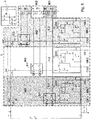
- Fig. 2 shows a schematic representation of the field device according to the invention with a sensor S, triple redundant measurement channels MK1, MK2, Mk3, triply redundant Stromeinstellkanälen IK1, IK2, IK3 and triple redundant Voterkanälen VK1, VK2, Vk3.
- the voter V comprises the Voterkanäle VK1, VK2, VK3, wherein the Voterkanälen VK1, VK2, VK3 at least parts of the comparator stages 11.1, 11.2, 11.3, the error detection stages 10.1, 10.2, 10.3 and the Ausschalttryn 9.1, 9.2, 9.3 assigned.
- the redundant analog current interface 8 includes the Stromeinstellkanäle IK1, IK2, IK3 and the Voterkanäle VK1, VK2, VK3.
- Fig. 3 shows a preferred embodiment of a deployable in the field device according to the invention redundant power interface 8 with safe redundant voter V.
- the field device according to the invention and in particular the analog current interface 8 are designed so that they meet the high security requirements in a desired safety-critical application, eg SIL 3.
- the voltage V1 and the resistor R1 represent the voltage supply, via which the 4-20mA current loop 2 is supplied with energy.
- the power supply is integrated into a remotely located output / evaluation unit, eg a PLC.
- the control / evaluation unit 6 the output signals supplied by the sensor S V5, V8, V4 - in the case of a sensor S represent the output signals V5, V8, V4 in particular measured values - along at least three redundant and / or diversely designed measuring channels MK1, MK2 , MK3 recycles and evaluates.
- the output signals supplied by the sensor S V5, V8, V4 - in the case of a sensor S represent the output signals V5, V8, V4 in particular measured values - along at least three redundant and / or diversely designed measuring channels MK1, MK2 , MK3 recycles and evaluates.
- FIG. 3 shown essential components of the current interface 8 according to the invention are shown in the following figures Fig. 4-7 shown and described in detail.
- the analog redundant power interface 8 is in Fig. 4 shown and described in detail in an enlarged view.
- the setpoints for the control of the transistors Q2, Q4, Q7 by the three parallel-connected current loop controls 5.1, 5.2, 5.3 correspond to the output signals V5, V8, V4 of the three not separately in Fig. 4 shown measuring channels MK1, MK2, MK3. Via the transistors Q2, Q4, Q7, the current is controlled, which is converted in the current sink 4 in power loss.
- the operational amplifiers U2A, U3A, U4A of the current loop controls 5.1, 5.2, 5.3 are each assigned their own power supply VCC1, VCC2, VCC3.
- This embodiment has the advantage that if one of the power supplies fails, no total failure of the field device occurs.
- the output current I flowing in the current loop 2 is automatically given via the current setting channel IK in which the largest current is set.
- the circuit is, so to speak, designed so that the Stromeinstellkanal IK wins with the largest set current.
- the field device according to the invention has the accuracy of the measuring channel MK, which processes and evaluates the measured values / setting values with the least accuracy.
- this measuring channel is the analogously designed measuring channel MK.
- each current setting channel IK1, IK2, IK3 or each current setting unit 7.1, 7.2, 7.3 is assigned an opening stage 9.1, 9.2, 9.3.
- the switch-off stages 9.1, 9.2, 9.3 are in Fig. 5 in addition to the current regulations 5.1, 5.2, 5.3 and the Stromeinstellein pulp 7.1, 7.2, 7.3 shown.
- the turn-off stages 9.1, 9.2, 9.3 are controlled by the voter V by the signals A, B, C, D, E, F.
- the turn-off stages 9.1, 9.2, 9.3 are configured twice in each of the measuring / Stromeinstellkanal MK, IK redundant, since the voter V is twice redundant in each of the measuring / Stromeinstellkanäle MK, IK is formed.
- Each switch-off stage 9.1, 9.2, 9.3 preferably consists of simple transistors Q9, Q10; Q12, Q13; Q14, Q15, which interrupt the control signal, and thus the base current of the current regulation transistors Q2, Q4, Q7. Once the base current is interrupted, transistor Q2, Q4, Q7 is open, and no current flows in current loop 2.
- the two remaining current adjustment channels IK in this case seamlessly take over the function of current adjustment on current loop 2; the adjustment of the current on the current loop 2 takes place automatically via one of the remaining current setting channels IK.
- the output signals of the operational amplifiers U2A, U3A, U4A are used.
- the corresponding output signals are in the figures Fig. 5 and Fig. 6 marked Ch1, Ch2, Ch3.
- each Stromeinstellkanal IK1, IK2, IK3 a Voterkanal VK1, VK2, VK3 assigned.
- Each Voterkanal VK1, VK2, VK3 is part of the dual redundant Voters V and consists of a comparator 11.1, 11.2, 11.3 and an error detection stage 10.1, 10.2, 10.3.
- Each comparator stage 11 has two comparator modules 12, which in turn have two comparators 18 and two voltage dividers 16. Since the signals supplied to the comparators 18 are analog signals, the comparators 18 must also be designed as analog components. This has the advantage that a malfunction Fch is detected immediately after its occurrence and switching over to one of the remaining current adjustment channels IK can likewise take place without a time delay. This ensures a seamless transition and thus a continuous operation of the field device.
- Each comparator module 12 consists, as already stated, of two analog comparators 18 and two voltage dividers 16.
- the tolerance given in a comparison of the accuracies of the channels essentially corresponds to the accuracy of the measuring channel MK with the lowest accuracy.
- the tolerance is preferably one percent of the current measured value.
- the measuring channel MK with the lowest accuracy is in principle the analog measuring channel MK.
- the output of a comparator stage 11 signals the difference between two signals which is greater than 1%.
- the comparator stages 11 are connected to the error detection stages 10, which detect in which of the measuring or Stromeinstellkanäle MK, IK a malfunction has occurred. For example, if (Ch1 ⁇ Ch2) ⁇ (Ch1 ⁇ Ch3), then the malfunction has occurred in channel IK1.
- the fault detection stage 10.1 controls the corresponding turn-off stage 9.1 such that the power control unit 7.1 of the channel IK1, in which the malfunction is present, is overridden.
- the voter V is designed twice redundant.
- the voter V allows the reliable detection of a malfunction Fch occurring in one of the current setting channels IK even in the case where the malfunction Fch occurs in a component of the voter V, that is, either in the comparator stage 11, the error detection stage 10, or in the turn-off stage 9 of each Stromeinstellkanals IK. If any component in one of the current adjustment channels IK fails, the adjustment function is taken over by one of the remaining current adjustment channels IK - the functionality of the field device is thus ensured even if a malfunction occurs in one of the current adjustment channels IK.
- the invention also detects errors that occur in the upstream measurement channels MK.
- the analogously configured dual-redundant voter V is designed such that it continues to operate in a channel IK even if the power supply fails. Thus, the field device remains operational. If a voltage supply fails, then current regulation 5 / current setting unit 7 of the affected channel IK fails. The function of the affected channel IK is taken over by one of the remaining channels IK. Since the error detection stage 10 of a channel IK receives information from the comparators 12 of the other channels IK, it is important that a channel IK does not affect the other channels IK when the voltage is lost. Therefore, the fault detection unit 10 is provided with pull-down resistors 13.
- Each pull-down resistor 13 is connected between a signal line and ground potential and causes the signal to be set at a defined level when a current setting channel IK is turned off and the control fails due to turning off a current setting channel IK. As long as the controller is working properly, the pull-down resistors 13 have no effect on the signal since they are relatively high-impedance. The pull-down resistors 13 ensure that a properly operating current adjustment channel IK is not turned off when the power supply in one of the other current adjustment channels IK fails.
- voltage monitoring elements are provided in each current adjustment channel IK, which detect over- or under-voltages. A voltage monitoring element can switch off the power supply of the affected Stromeinstellkanals IK in case of malfunction.
- Each Voterkanal VK comprises a part of the comparator stage 11, a part of the error detection stages 10 and a part of the Ausschaltcut 9.
- Each Voterkanal VK is designed as an integrated part of the associated measurement channel MK and the associated Stromeinstellkanals IK.
- the comparator stage 11.1 has two comparator modules 12 which compare the output signals Ch1 of the associated Stromeinstellkanals IK1 with the output signals Ch2, Ch3 of the remaining Stromeinstellkanäle IK2, IK3.
- the output signals of the two comparators 18 of each of the comparator modules 12 form the input signals for the downstream NAND gate 22.1 and the downstream NAND gate 22.2.
- the output signals F, E of the NAND gate 22.1 and the NAND gate 22.2 are fed to the error detection stage 10.1.
- the error detection stage 10.1 connected downstream of the comparator stage 11.1, it is determined in which of the measurement or current setting channels MK, IK a malfunction has occurred.
- the error detection stages 10.1, 10.2, 10.3 are in each case a logic stage which is composed of two NAND gates 15.1, 15.2. In the following, let's take a closer look at the first Voter channel VK1: At the inputs of the first NAND gate 15.2 are the output signals E, F of the comparator stage 11.1 of the first Voter channel VK1. The first Voterkanal VK1 is assigned to the first measuring channel MK1.
- the redundant output signals B, D of the comparator stages 11.2, 11.3 of the second VOTerkanals VK2 and the third Voterkanals VK3 are at the inputs of the second NAND gate 15.1.
- the output signals of the first NAND gate 15.2 and the second NAND gate 15.1 form the control signals for the downstream shutdown 9.1. As long as at least one input signal of the first NAND gate 15.2 and at least one input signal of the second NAND gate 15.1 are in the logic "0" state, this does not happen. As soon as both input signals of the first NAND gate 15.2 or both input signals of the second NAND gate 15.1 are in the logic "1" state, the corresponding current setting channel IK1 is switched off directly by the corresponding switch-off stage 9.1. The same applies to the two other Stromeinstellkanäle VK2, VK3.
- control / evaluation unit 6 is configured as dynamically reconfigurable or reconfigurable or simply as FPGA, and if two channels MK, IK are implemented in the FPGA, then two channels MK, IK are connected to one power supply. Therefore, the power supply from a single channel MK, IK can not be switched off.
- the alarm current module 14 is designed such that it can detect multiple malfunctions Fch in different measurement channels MK or current adjustment channels IK.
- the alarm current module 14 corresponds to a fourth current setting channel IK4, which can be triggered to set a fault current of ⁇ 22 mA, the so-called alarm current.
- the triggering is done by the controller 20 for the alarm current control 19. Since this alarm current in a 4-20mA current loop is greater than all other currents flowing in the analog current interface 8, it automatically takes over the control.
- the alarm power module 14 is preferably powered by its own power supply VCC4.
- the alarm power module 14 may also be triggered by other modules, such as by a voltage monitor or by reconfiguration controls. These embodiments are in Figure 7 not shown separately.
- the signals of the error detection stages 10 are preferably forwarded to the reconfiguration controller, which causes the reconfiguration of the faulty measurement channels MK. These are shown and described in the already mentioned above DE 10 2012 106 652.3 in the figures Fig. 1 . Fig. 2 and Fig. 3 , The essential differences with respect to the present invention are that the voter V in the present invention is implemented in the analog power interface 8 and that the power interface 8 is redundant.
Description
Die Erfindung betrifft ein Feldgerät zur Bestimmung oder Überwachung einer Prozessgröße in der Automatisierungstechnik. Das Feldgerät ist so ausgestaltet, dass es einem Sicherheitsstandard genügt, der in einer vorgegebenen sicherheitskritischen Anwendung gefordert ist. Weiterhin umfasst das Feldgerät einen Sensor, der nach einem definierten Messprinzip arbeitet, und eine Kontroll-/Auswerteeinheit, die die vom Sensor gelieferten Messdaten entlang von zumindest drei redundanten und/oder diversitär ausgelegten Messkanälen aufbereitet und auswertet. Eine entsprechende Lösung ist aus der
In der Automatisierungstechnik, insbesondere in der Prozessautomati-sierungstechnik, werden Feldgeräte eingesetzt, die zur Bestimmung und Überwachung von Prozessvariablen dienen. Beispiele für derartige Feldgeräte sind Füllstandsmessgeräte, Durchflussmessgeräte, Analysemessgeräte, Druck- und Temperaturmessgeräte, Feuchte- und Leitfähigkeitsmessgeräte, Dichte und Viskositätsmessgeräte. Die Sensoren dieser Feldgeräte erfassen die entsprechenden Prozessvariablen, z.B. den Füllstand, den Durchfluss, den pH-Wert, die Stoffkonzentration, den Druck, die Temperatur, die Feuchte, die Leitfähigkeit, die Dichte oder die Viskosität.In automation technology, in particular in process automation technology, field devices are used which are used to determine and monitor process variables. Examples of such field devices are level gauges, flowmeters, analyzers, pressure and temperature measuring devices, humidity and conductivity meters, density and viscosity meters. The sensors of these field devices detect the corresponding process variables, e.g. level, flow, pH, substance concentration, pressure, temperature, humidity, conductivity, density or viscosity.
Unter den Begriff 'Feldgeräte' werden in Verbindung mit der Erfindung aber auch Aktoren, z. B. Ventile oder Pumpen, subsumiert, über die beispielsweise der Durchfluss einer Flüssigkeit in einer Rohrleitung oder der Füllstand in einem Behälter veränderbar ist. Eine Vielzahl solcher Feldgeräte wird von der Firmengruppe Endress + Hauser angeboten und vertrieben.The term 'field devices' in connection with the invention but also actuators, z. As valves or pumps, subsumed, via which, for example, the flow of a liquid in a pipeline or the level in a container is variable. A large number of such field devices are offered and distributed by the Endress + Hauser Group.
In der Regel sind Feldgeräte in modernen automatisierungstechnischen Anlagen über Kommunikationsnetzwerke, wie HART- Multidrop, Punkt zu Punkt Verbindung, Profibus, Foundation Fieldbus, mit einer übergeordneten Einheit verbunden, die als Leitsysteme oder Leitwarte bezeichnet wird. Diese übergeordnete Einheit dient zur Prozesssteuerung, zur Prozessvisualisierung, zur Prozessüberwachung sowie zur Inbetriebnahme und zum Bedienen der Feldgeräte. Für den Betrieb von Feldbussystemen notwendige Zusatz-komponenten, die direkt an einen Feldbus angeschlossen sind und die insbesondere zur Kommunikation mit den übergeordneten Einheiten dienen, werden ebenfalls häufig als Feldgeräte bezeichnet. Bei diesen Zusatz-komponenten handelt es sich z. B. um Remote l/Os, Gateways, Linking Devices, Controller oder Wireless Adapter.As a rule, field devices in modern automation systems are connected via communication networks, such as HART multidrop, point-to-point connection, Profibus, Foundation Fieldbus, to a superordinated unit, which is referred to as a control system or control room. This higher-level unit is used for process control, process visualization, process monitoring and commissioning and for operating the field devices. Additional components necessary for the operation of fieldbus systems, which are directly connected to a fieldbus and which in particular serve for communication with the higher-level units, are also frequently referred to as field devices. These additional components are, for. For example, remote I / Os, gateways, linking devices, controllers or wireless adapters.
Je nach Anwendungsfall müssen die Feldgeräte unterschiedlichsten Sicherheitsanforderungen genügen. Um den jeweiligen Sicherheits-anforderungen, z.B. der IEC61508 (SIL-Standard 'Safety Integrity Level') zu genügen, müssen die Feldgeräte redundant und/oder diversitär ausgelegt sein.Depending on the application, the field devices must meet a wide variety of security requirements. In order to meet the respective security requirements, e.g. IEC61508 (SIL standard 'Safety Integrity Level'), the field devices must be redundant and / or diversified.
Redundanz bedeutet erhöhte Sicherheit durch doppelte oder mehrfache Auslegung aller sicherheitsrelevanter Hard- und Software-Komponenten. Diversität bedeutet, dass die in den unterschiedlichen Messkanälen befindlichen Hardware-Komponenten, wie z.B. ein Mikroprozessor, von unterschiedlichen Herstellern stammen und/oder dass sie von unterschiedlichem Typ sind. Im Falle von Software-Komponenten erfordert die Diversität, dass die in den Mikroprozessoren gespeicherte Software aus unterschiedlichen Quellen, sprich von unterschiedlichen Herstellern bzw. Programmierern stammt. Durch alle diese Maßnahmen soll sichergestellt werden, dass ein sicherheitskritischer Ausfall des Feldgeräts ebenso wie das Auftreten von gleichzeitig auftretenden systematischen Fehlern bei der Messwertbereitstellung mit hoher Wahrscheinlichkeit ausgeschlossen ist.Redundancy means increased safety through double or multiple design of all safety-related hardware and software components. Diversity means that the hardware components located in the different measurement channels, e.g. a microprocessor, from different manufacturers and / or that they are of different types. In the case of software components, diversity requires that the software stored in the microprocessors come from different sources, ie from different manufacturers or programmers. All these measures are intended to ensure that a safety-critical failure of the field device as well as the occurrence of simultaneously occurring systematic errors in the provision of the measured value is excluded with a high degree of probability.
Ein Beispiel für eine sicherheitsrelevante Applikation ist die Füllstands-überwachung in einem Tank, in dem eine brennbare oder auch eine nicht brennbare, dafür aber wassergefährdende Flüssigkeit gelagert ist. Hier muss sichergestellt sein, dass die Zufuhr von Flüssigkeit zu dem Tank sofort unterbrochen wird, sobald ein maximal zulässiger Füllstand erreicht ist. Dies wiederum setzt voraus, dass das Messgerät hoch zuverlässig den Füllstand detektiert und fehlerfrei arbeitet.An example of a safety-relevant application is the level monitoring in a tank in which a flammable or a non-flammable, but water-polluting liquid is stored. Here it must be ensured that the supply of liquid to the tank is interrupted immediately as soon as a maximum permissible level is reached. This, in turn, requires that the meter reliably detects the level and operates without errors.
Zwar ist bei den bekannten Lösungen der Messkanal redundant und/oder diversitär ausgelegt, jedoch stellt der Voter, üblicherweise ein Mikroprozessor, die Achillesferse eines Feldgeräts dar, das hohen und höchsten Sicherheitsanforderungen genügen soll. Der Mikroprozessor ist monolithisch ausgestaltet. Tritt hier ein gefahrbringender Fehler (entsprechend der Nomenklatur des zuvor genannten Standards) auf, so versagt das Feldgerät. Um die Anforderungen von SIL 3 zu erfüllen, darf der Anteil der gefahrbringenden Fehler zu der Anzahl aller möglichen Fehler bei maximal einem Prozent liegen. Mit einem herkömmlichen Mikroprozessor ist dieser Sicherheitslevel nicht zu erreichen.Although in the known solutions the measuring channel is designed to be redundant and / or diverse, however, the voter, usually a microprocessor, represents the Achilles heel of a field device which should meet high and highest safety requirements. The microprocessor is designed monolithic. If a dangerous fault occurs (according to the nomenclature of the aforementioned standard), the field device fails. In order to meet the requirements of
Um dieses Problem zu lösen, wird in der nicht vorveröffentlichten
- eine Komparatorstufe, die die von den einzelnen Messkanälen gelieferten Ausgangssignale miteinander vergleicht;
- eine Fehlererkennungsstufe, die durch geeignete Verknüpfung der Ausgangssignale der Komparatorstufe einen in einem Messkanal auftretenden Fehler erkennt, und
- eine Ausgangsauswahlstufe.
- a comparator stage that compares the output signals provided by the individual measurement channels with each other;
- an error detection stage which detects an error occurring in a measuring channel by appropriately linking the output signals of the comparator stage, and
- an output selection stage.
Die Druckschrift
Bislang ist kein Feldgerät bekannt, das die hohe Sicherheitsstufe auch im Bereich des Stromausgangsmoduls z.B. bei einem 4-20mA Zwei- oder Vier-Draht-Feldgerät erfüllt.So far, no field device is known, which has the high security level even in the area of the current output module, e.g. in a 4-20mA two- or four-wire field device.
Der Erfindung liegt die Aufgabe zugrunde, ein Feldgerät vorzuschlagen, das sich durch eine erhöhte funktionale Sicherheit auszeichnet.The invention has for its object to provide a field device, which is characterized by increased functional safety.
Die Aufgabe wird durch ein Feldgerät zur Bestimmung oder Überwachung einer Prozessgröße in der Automatisierungstechnik nach Anspruch 1 gelöst.The object is achieved by a field device for determining or monitoring a process variable in automation technology according to
Gemäß einer bevorzugten Ausgestaltung des erfindungsgemäßen Feldgeräts weist jeder Stromeinstellkanal eine Stromeinstelleinheit und eine Stromregelung auf, wobei die Stromeinstelleinheit und die Stromregelung parallel geschaltet sind.According to a preferred embodiment of the field device according to the invention, each Stromeinstellkanal a Stromeinstelleinheit and a current control, wherein the Stromeinstelleinheit and the current control are connected in parallel.
Weiterhin ist vorgesehen, dass der Voter aus mehreren Komponenten besteht, die zumindest teilweise oder in Gänze zweifach redundant ausgelegt sind.Furthermore, it is provided that the voter consists of several components that are at least partially or completely designed twice redundant.
Insbesondere wird vorgeschlagen, dass der Voter ein Mehrheitsvoter ist, der mehrere Voterkanäle aufweist, wobei in jedem Voterkanal folgende Komponenten zu finden sind: eine Komparatorstufe, über die die von den einzelnen Stromeinstellkanälen gelieferten Ausgangssignale miteinander verglichen werden, eine Fehlererkennungsstufe, die durch geeignete Verknüpfung der Ausgangssignale der den Voterkanälen zugeordneten Komparatorstufen eine in einem Messkanal oder in einem Stromeinstellkanal auftretende Fehlfunktion erkennt, und eine Ausschaltstufe, die den Stromeinstellkanal ausschaltet, in dem die Fehlererkennungsstufe eine Fehlfunktion detektiert.In particular, it is proposed that the voter be a majority voter having a plurality of voter channels, wherein the following components are found in each voter channel: a comparator stage through which the output signals provided by the individual current setting channels are compared with each other, an error detection stage provided by appropriately linking the voters Output signals of the comparator stages associated with the voter channels detects a malfunction occurring in a measurement channel or in a current setting channel, and a turn-off stage which turns off the current setting channel in which the error detection stage detects a malfunction.
Eine vorteilhafte Weiterbildung des erfindungsgemäßen Feldgeräts sieht vor, dass jeder Voterkanal einen Teil der Komparatorstufe, einen Teil der Fehlererkennungseinheit und einen Teil der Ausschaltstufe umfasst, und dass jeder Voterkanal als integrierter Bestandteil des zugehörigen Messkanals und des zugehörigen Stromeinstellkanals ausgestaltet ist.An advantageous development of the field device according to the invention provides that each Voterkanal comprises part of the comparator stage, part of the error detection unit and part of the Ausschaltstufe, and that each Voterkanal is designed as an integrated part of the associated measurement channel and the associated Stromeinstellkanals.
Darüber hinaus wird vorgeschlagen, dass die Komparatorstufe für jeden Voterkanal zwei Komparatormodule aufweist, die die Ausgangssignale des zugehörigen Stromeinstellkanals mit den Ausgangssignalen der verbleibenden Stromeinstellkanäle vergleicht.In addition, it is proposed that the comparator stage for each Voterkanal comprises two comparator modules, which compares the output signals of the associated Stromeinstellkanals with the output signals of the remaining Stromeinstellkanäle.
Bevorzugt handelt es sich bei den Fehlererkennungsstufen jeweils um eine Logikstufe, die aus zwei NAND Gattern aufgebaut ist, wobei an den Eingängen des ersten NAND Gatters die Ausgangssignale der Komparatoren eines ersten Voterkanals anliegen, der einem ausgewählten Messkanal zugeordnet ist, und wobei an dem zweiten NAND Gatter die zu den Eingängen des ersten NAND Gatters redundanten Ausgangssignale der Komparatoren des zweiten Voterkanals und des dritten Voterkanals anliegen, und wobei die Ausgangssignale des ersten NAND Gatters und des zweiten NAND Gatters die Steuersignale für die nachgeschaltete Ausschaltstufe bilden.Preferably, each of the error detection stages is a logic stage constructed of two NAND gates, the output signals of the comparators of a first Voter channel being associated with a selected measurement channel at the inputs of the first NAND gate, and at the second NAND Gate applied to the inputs of the first NAND gate redundant outputs of the comparators of the second Voterkanals and the third Voterkanals, and wherein the outputs of the first NAND gate and the second NAND gate constitute the control signals for the downstream Ausschaltstufe.
Bevorzugt ist jedem Messkanal bzw. jedem Stromeinstellkanal eine eigene Spannungsversorgung zugeordnet. Diese Ausgestaltung hat den Vorteil, dass es bei Wegfall einer der Spannungsversorgungen zu keinem Totalausfall des Feldgeräts kommt.Each measuring channel or each current setting channel is preferably assigned its own power supply. This embodiment has the advantage that when one of the power supplies fails, no total failure of the field device occurs.
Als besonders vorteilhaft wird es erachtet, wenn ein Alarmstrommodul vorgesehen ist, das so ausgestaltet ist, dass es einen Fehlerstrom, z.B. von 22mA, setzt, wenn in zumindest zwei Messkanälen bzw. in zwei Stromeinstellkanälen gleichzeitig eine Fehlfunktion auftritt. Hierdurch wird verhindert, dass die Stromschnittstelle instabil wird.It is considered particularly advantageous if an alarm current module is provided which is designed such that it sets a fault current, eg of 22 mA, if a malfunction occurs simultaneously in at least two measurement channels or in two current adjustment channels. This prevents the current interface from becoming unstable.
Weiterhin wird vorgeschlagen, dass die Kontroll-/Auswerteeinheit mit Messkanälen bzw. Stromeinstellkanälen die zugehörigen Komponenten des Voters bzw. der Voterkanäle zumindest teilweise als rekonfigurierbarer Logikbaustein mit mehreren partiell dynamisch rekonfigurierbaren Funktionsmodulen in den Messkanälen bzw. in den Stromeinstellkanälen ausgebildet ist.Furthermore, it is proposed that the control / evaluation unit with measuring channels or current setting channels is at least partially designed as a reconfigurable logic module with a plurality of partially dynamically reconfigurable functional modules in the measuring channels or in the current setting channels.
Darüber hinaus ist eine Rekonfigurationssteuerung vorgesehen, die Funktionsmodule in den Messkanälen oder den Stromeinstellkanälen in Abhängigkeit von der jeweils definierten sicherheitskritischen Anwendung so konfiguriert, dass das Feldgerät dem geforderten Sicherheitsstandard genügt.In addition, a reconfiguration control is provided, the functional modules in the measurement channels or the Stromeinstellkanälen depending on the particular safety-critical application configured so that the field device meets the required safety standard.
Insbesondere ist der Rekonfigurationssteuerung zumindest ein Mikroprozessor zugeordnet, der die Funktionsmodule eines Messkanals oder eines Stromeinstellkanals, in dem ein Fehler detektiert wird, partiell dynamisch rekonfiguriert.In particular, the reconfiguration controller is assigned at least one microprocessor which partially dynamically reconfigures the functional modules of a measurement channel or of a current adjustment channel in which an error is detected.
Im Zusammenhang mit der Erfindung wird weiterhin vorgeschlagen, dass zumindest einer der Messkanäle und/oder der Stromeinstellkanäle analogbasiert in einem FPAA konfiguriert ist.In connection with the invention it is further proposed that at least one of the measurement channels and / or the current adjustment channels is configured analog-based in an FPAA.
Es wird zusätzlich angeregt, dass die einzelnen Messkanäle oder Stromeinstellkanäle so voneinander beabstandet sind, dass eine Temperatur- und/oder eine Spannungsänderung in einem Messkanal oder Stromeinstellkanal keinen Einfluss auf einen benachbarten Messkanal oder Stromeinstellkanal haben/hat.It is additionally suggested that the individual measuring channels or Stromeinstellkanäle are spaced apart so that a temperature and / or a voltage change in a measuring channel or Stromeinstellkanal have / have no effect on an adjacent measuring channel or Stromeinstellkanal.
Bevorzugt ist der zumindest eine Mikroprozessor in einem statischen Bereich des Logikbausteins permanent konfiguriert.Preferably, the at least one microprocessor is permanently configured in a static region of the logic device.
Die Erfindung wird anhand der nachfolgenden Figuren näher erläutert. Es zeigt:
-
Fig. 1 : ein Blockschaltbild eines aus dem Stand der Technik bekannten Stromausgangsmoduls, -
Fig. 2 : eine schematische Darstellung einer Ausführungsform des erfindungsgemäßen Feldgeräts mit Sensor, dreifach redundanten Messkanälen, dreifach redundanten Stromeinstellkanälen, zweifach redundanten Voterkanälen und zweifach redundanten Ausschaltstufen, -
Fig. 3 : eine bevorzugte Ausgestaltung einer bei dem erfindungsgemäßen Feldgerät einsetzbaren redundanten Stromschnittstelle mit redundantem Voter, -
Fig. 4 : eine vergrößerte Darstellung der erfindungsgemäßen Stromschnittstelle ausFig. 3 , -
Fig. 5 : eine vergrößerte Darstellung der erfindungsgemäßen Stromschnittstelle mit den zugehörigen Ausschaltstufen für die Stromeinstellkanäle ausFig. 3 , -
Fig. 6 : eine vergrößerte Darstellung des zweifach redundanten, sicheren Voters mit Komparatorstufen, Fehlererkennungsstufen und Ausschaltstufen ausFig. 3 , und -
Fig. 7 : eine vergrößerte Darstellung des zweifach redundanten, sicheren Voters mit Fehlererkennungsstufen, Ausschaltstufen und einem Alarmstrommodul ausFig. 3 .
-
Fig. 1 FIG. 2 is a block diagram of a current output module known from the prior art. FIG. -
Fig. 2 : a schematic representation of an embodiment of the field device according to the invention with sensor, triple redundant measurement channels, triply redundant Stromeinstellkanälen, dual redundant Voterkanälen and dual redundant switch-off, -
Fig. 3 FIG. 2 shows a preferred embodiment of a redundant current interface with redundant voter that can be used in the field device according to the invention, FIG. -
Fig. 4 : An enlarged view of the current interface of the inventionFig. 3 . -
Fig. 5 : An enlarged view of the current interface according to the invention with the associated switch-off stages for StromeinstellkanäleFig. 3 . -
Fig. 6 : An enlarged view of the dual redundant, safe Voter with comparator stages, fault detection stages and off stagesFig. 3 , and -
Fig. 7 : An enlarged view of the dual redundant, safe Voter with fault detection stages, power off stages and an alarm power module offFig. 3 ,
Der über die Stromschleife 2 fließende Strom I wird über eine Stromregelung 5 und eine Stromeinstelleinheit 7 so eingestellt, dass der eingestellte Strom I die ermittelte Prozess- oder Stellgröße eindeutig und mit hoher Genauigkeit repräsentiert. Üblicherweise wird in der Automatisierungstechnik der 4-20mA Standard verwendet. Hierbei repräsentiert ein Strom von 4 mA in der Stromschleife z.B. den minimalen Wert der Prozessgröße und ein Strom von 20 mA z.B. den maximalen Wert der Prozessgröße. Die 4-20mA Technik ist weitgehend störunempfindlich, sie ist im explosionsgefährdeten Bereich einsetzbar und findet bei industriellen Anwendungen häufig Verwendung.The current I flowing through the
Etabliert hat sich in der Automatisierungstechnik die sog. Zweileitertechnik, bei der über die Stromschleife 2 nicht nur die Mess- oder Stellwerte übermittelt werden, sondern über die der Sensor/Aktor auch mit Energie versorgt wird. Für die Mess-/Stellaufgabe steht dem Feldgerät somit nur eine begrenzte Leistung zur Verfügung. Diese Leistung hängt von der Versorgungsspannung und dem den aktuellen Messwert/Stellwert repräsentierenden Strom ab. Um eine dauernde Verfügbarkeit des Feldgeräts zu gewährleisten, sind herkömmliche Feldgeräte so dimensioniert, dass sie mit der minimal zur Verfügung stehenden Leistung auskommen, d.h. sie benötigen für den Mess- oder Stellbetrieb nur die bei minimalem Strom und minimaler Spannung anstehende Leistung. Steht mehr Leistung zur Verfügung, wird diese zusätzliche Leistung üblicherweise in einer Stromsenke 4 in Verlustleistung umgesetzt.Automation technology has established the so-called two-wire technology, in which not only the measured or manipulated values are transmitted via the
Das in
Der Transistor Q2 der Stromeinstelleinheit 7 steuert den Strom, der von dem positiven Anschluss 3a zu der Stromsenke 4 fließt. Die Stromsenke 4 liegt auf Bezugspotential, vorzugsweise auf Masse GND. Der Strom fließt zum negativen Anschluss 3b über den Messwiderstand R12. Hierdurch wird eine Spannung zwischen dem negativen Anschluss und Masse GND erzeugt, die proportional zum fließenden Strom ist. Diese Spannung wird als Referenzspannung zur Steuerung des Transistors Q2 und somit zur Einstellung des Stroms in der Stromschleife 2 verwendet. Die Regelung des eingestellten Stroms erfolgt über die Stromschleifenregelung 5. Kernstück der Stromschleifenregelung 5 ist der Operationsverstärker U2A. Der Operationsverstärker U2A steuert den Transistor Q1 und auch den Transistor Q2 derart, dass am Plusausgang des Operationsverstärkers U2A die Summe der Spannungen gleich Null ist. Ist diese Bedingung erfüllt, so ist der Strom I durch den Messwiderstand R12 und in der Stromschleife 2 proportional zu dem Sollwert, der durch die Spannung V5 repräsentiert wird.The transistor Q2 of the
Erfolgt die Energieversorgung des Feldgeräts über dieselbe Stromschleife 2, die auch zur Übermittelung der Mess- oder Stellwerte des Feldgeräts verwendet wird, so dient die Stromsenke 4 dazu, den Strom, der von dem Feldgerät nicht benötigt wird, gegen Masse GND abzuleiten und somit in Verlustleistung umzuwandeln. Erfolgt die Energieversorgung des Feldgeräts über eine separate Stromleitung, so kann die Stromsenke 4 entfallen, bzw. sie kann durch eine Kurzschlussschaltung ersetzt werden.If the power supply of the field device via the same
Nicht konkret dargestellt ist in
Die in
- drei parallel geschaltete Stromeinstellkanäle IK1, IK2, IK3 (sh.
Fig. 4 ); - einen zweifach redundanten Voter V, der eine Fehlfunktion in einem der Messkanäle MK1, MK2, MK3 und/oder der Stromeinstellkanäle IK1, IK2, IK3 erkennt (sh.
Fig. 6 ); - eine dreifach redundante Ausschaltstufe 9.1, 9.2, 9.3, über die ein Stromeinstellkanal IK1, IK2, IK3 abgeschaltet wird, wenn der Voter V in dem Messkanal MK1, MK2, MK3 oder in dem zugehörigen Stromeinstellkanal IK1, IK2, IK3 eine Fehlfunktion Fch1, Fch2, Fch3 erkennt (sh.
Fig. 5 ); ein Alarmstrommodul 14, das einen Alarmstrom stellt, wenn in zumindest zwei Messkanälen MK1, MK2, MK3 und/oder Stromeinstellkanälen IK1, IK2, IK3 gleichzeitig eine Fehlfunktion Fch auftritt (sh.Fig. 7 ).
- three parallel Stromeinstellkanäle IK1, IK2, IK3 (sh.
Fig. 4 ); - a dual-redundant voter V, which detects a malfunction in one of the measurement channels MK1, MK2, MK3 and / or Stromeinstellkanäle IK1, IK2, IK3 (see.
Fig. 6 ); - a triple redundant switch-off 9.1, 9.2, 9.3, via which a Stromeinstellkanal IK1, IK2, IK3 is turned off when the voter V in the measuring channel MK1, MK2, MK3 or in the associated Stromeinstellkanal IK1, IK2, IK3 a malfunction Fch1, Fch2, Fch3 recognizes (sh.
Fig. 5 ); - an alarm
current module 14, which provides an alarm current if at least two measurement channels MK1, MK2, MK3 and / or Stromeinstellkanälen IK1, IK2, IK3 simultaneously a malfunction Fch occurs (see.Fig. 7 ).
Die analoge, redundant ausgelegte Stromschnittstelle 8 ist in
Im gezeigten Fall ist den Operationsverstärkern U2A, U3A, U4A der Stromschleifenregelungen 5.1, 5.2, 5.3 jeweils eine eigene Spannungsversorgung VCC1, VCC2, VCC3 zugeordnet. Diese Ausgestaltung hat den Vorteil, dass bei Wegfall einer der Spannungsversorgungen kein Totalausfall des Feldgeräts auftritt.In the case shown, the operational amplifiers U2A, U3A, U4A of the current loop controls 5.1, 5.2, 5.3 are each assigned their own power supply VCC1, VCC2, VCC3. This embodiment has the advantage that if one of the power supplies fails, no total failure of the field device occurs.
Über die Schattierungen in
Bei der in
Tritt in einem der Messkanäle MK oder in einem der Stromeinstellkanäle IK eine Fehlfunktion auf, so stellt der entsprechende Stromeinstellkanal IK einen falschen Strom ein. Ist dieser falsch eingestellte Strom höher als der Strom, der in den beiden korrekt eingestellten Stromeinstellkanälen IK eingestellt ist, dann wird in der Stromschleife 2 der falsche Strom eingestellt und das Feldgerät liefert einen falschen Messwert. Als Folge des falsch eingestellten Stromwertes wird auf der Stromschleife ein fehlerhafter Messwert/Stellwert übertragen. Um die angestrebte hohe Sicherheitsstufe auch noch im Falle des Auftretens einer Fehlfunktion Fch zu gewährleisten, ist jedem Stromeinstellkanal IK1, IK2, IK3 bzw. jeder Stromeinstelleinheit 7.1, 7.2, 7.3 eine Ausschaltstufe 9.1, 9.2, 9.3 zugeordnet.If a malfunction occurs in one of the measurement channels MK or in one of the current adjustment channels IK, then the corresponding current adjustment channel IK sets a false current. If this incorrectly set current is higher than the current set in the two correctly set current setting channels IK, then the wrong current is set in the
Die Ausschaltstufen 9.1, 9.2, 9.3 sind in
Bevorzugt besteht jede Ausschaltstufe 9.1, 9.2, 9.3 aus einfachen Transistoren Q9, Q10; Q12, Q13; Q14, Q15, die das Steuersignal, und somit den Basisstrom der für die Stromregelung verantwortlichen Transistoren Q2, Q4, Q7 unterbrechen. Sobald der Basisstrom unterbrochen ist, ist der Transistor Q2, Q4, Q7 offen, und es fließt kein Strom in der Stromschleife 2. Die beiden verbleibenden Stromeinstellkanäle IK übernehmen in diesem Fall nahtlos die Funktion der Stromeinstellung auf der Stromschleife 2; die Einstellung des Stroms auf der Stromschleife 2 erfolgt automatisch über einen der verbleibenden Stromeinstellkanäle IK.Each switch-off stage 9.1, 9.2, 9.3 preferably consists of simple transistors Q9, Q10; Q12, Q13; Q14, Q15, which interrupt the control signal, and thus the base current of the current regulation transistors Q2, Q4, Q7. Once the base current is interrupted, transistor Q2, Q4, Q7 is open, and no current flows in
Die Übernahme der Einstellfunktion durch einen der verbleibenden Stromeinstellkanäle IK kann folgendermaßen genutzt werden: Wie aus
Wie bereits zuvor erwähnt, ist es mit der erfindungsgemäßen Lösung möglich, den korrekten Betrieb des Feldgeräts auch dann noch zu gewährleisten, wenn ein Mess- oder Stromeinstellkanal MK, IK ausfällt. Sobald in einem der Mess- oder Stromeinstellkanäle MK, IK ein von dem Sollwert abweichender Stromwert ermittelt wird und somit eine Fehlfunktion Fch auftritt, wird der fehlerbehaftete Mess-oder Stromeinstellkanal MK, IK ausgeschaltet. Seine Funktion wird automatisch von einem der verbleibenden Mess- oder Stromeinstellkanäle MK, IK übernommen.As already mentioned above, it is possible with the solution according to the invention to guarantee the correct operation of the field device even if a measuring or current setting channel MK, IK fails. As soon as a current value deviating from the desired value is determined in one of the measuring or current setting channels MK, IK and thus a malfunction Fch occurs, the faulty measuring or current setting channel MK, IK is switched off. Its function is automatically taken over by one of the remaining measuring or Stromeinstellkanäle MK, IK.
Um die Fehlfunktion zu erkennen, ist jedem Stromeinstellkanal IK1, IK2, IK3 ein Voterkanal VK1, VK2, VK3 zugeordnet. Jeder Voterkanal VK1, VK2, VK3 ist Teil des zweifach redundanten Voters V und besteht aus einer Komparatorstufe 11.1, 11.2, 11.3 und einer Fehlererkennungsstufe 10.1, 10.2, 10.3. Jede Komparatorstufe 11 weist zwei Komparatormodule 12 auf, die wiederum zwei Komparatoren 18 und zwei Spannungsteiler 16 aufweisen. Da es sich bei den Signalen, die den Komparatoren 18 zugeführt werden, um analoge Signale handelt, müssen auch die Komparatoren 18 als analoge Komponenten ausgelegt sein. Dies hat den Vorteil, dass eine Fehlfunktion Fch unmittelbar nach ihrem Auftreten erkannt wird und das Umschalten auf einen der verbleibenden Stromeinstellkanäle IK gleichfalls ohne Zeitverzögerung erfolgen kann. Hierdurch werden ein nahtloser Übergang und damit ein kontinuierlicher Betrieb des Feldgeräts sichergestellt.To detect the malfunction, each Stromeinstellkanal IK1, IK2, IK3 a Voterkanal VK1, VK2, VK3 assigned. Each Voterkanal VK1, VK2, VK3 is part of the dual redundant Voters V and consists of a comparator 11.1, 11.2, 11.3 and an error detection stage 10.1, 10.2, 10.3. Each
Jedes Komparatormodul 12 besteht, wie bereits gesagt, aus zwei analogen Komparatoren 18 und zwei Spannungsteilern 16. Die Toleranz, die bei einem Vergleich der Genauigkeiten der Kanäle gegeben ist, entspricht im Wesentlichen der Genauigkeit des Messkanals MK mit der geringsten Genauigkeit. Bevorzugt liegt die Toleranz bei einem Prozent des aktuellen Messwertes. Der Messkanal MK mit der geringsten Genauigkeit ist prinzipiell der analoge Messkanal MK. Der Ausgang einer Komparatorstufe 11 signalisiert die Differenz zwischen zwei Signalen, die größer als 1% ist.Each
In einer Formel lässt sich dies wie folgt ausdrücken:
(CH3 ≠ CH1) ist gegeben, wenn (CH3 > Ch1x0.99)n(Ch1 > Ch3x0.99), wobei die Toleranz 1,01%/-1% beträgt.
Darüber hinaus müssen für die korrekte Berechnung auch die Toleranzen der Komparatoren 12 und der Widerstände der Spannungsteiler 16 berücksichtigt werden. Unter der Annahme, dass die Komponenten ein ideales Verhalten und somit keine Abweichungen aufweisen, wird der Faktor 0,99 über die Bemessung der Widerstände der Spannungsteiler 16 realisiert. Beispielsweise beträgt R40 470kΩ und R41 4,7kΩ.In a formula, this can be expressed as follows:
(CH3 ≠ CH1) is given when (CH3> Ch1x0.99) n (Ch1> Ch3x0.99), where the tolerance is 1.01% / - 1%.
In addition, the tolerances of the
Die Komparatorstufen 11 sind mit den Fehlererkennungsstufen 10 verbunden, die erkennen, in welchem der Mess- oder Stromeinstellkanäle MK, IK eine Fehlfunktion aufgetreten ist. Gilt beispielsweise (Ch1≠Ch2) ∧ (Ch1≠Ch3), dann ist die Fehlfunktion im Kanal IK1 aufgetreten. Die Fehlererkennungsstufe 10.1 steuert die entsprechende Ausschaltstufe 9.1 derart, dass die Stromstelleinheit 7.1 des Kanals IK1, in dem die Fehlfunktion vorliegt, außer Kraft gesetzt wird.The comparator stages 11 are connected to the error detection stages 10, which detect in which of the measuring or Stromeinstellkanäle MK, IK a malfunction has occurred. For example, if (Ch1 ≠ Ch2) ∧ (Ch1 ≠ Ch3), then the malfunction has occurred in channel IK1. The fault detection stage 10.1 controls the corresponding turn-off stage 9.1 such that the power control unit 7.1 of the channel IK1, in which the malfunction is present, is overridden.
Wie aus den Figuren
Der analog ausgestaltete zweifach redundante Voter V ist so ausgestaltet, dass er auch bei Ausfall der Spannungsversorgung in einem Kanal IK weiterarbeitet. Somit bleibt das Feldgerät betriebsbereit. Versagt eine Spannungsversorgung, so fällt Stromregelung 5/Stromeinstelleinheit 7 des betroffenen Kanals IK aus. Die Funktion des betroffenen Kanals IK wird von einem der verbleibenden Kanäle IK übernommen. Da die Fehlererkennungsstufe 10 eines Kanals IK Information von den Komparatoren 12 der anderen Kanäle IK erhält, ist es wichtig, dass ein Kanal IK bei Wegfall der Spannung die anderen Kanäle IK nicht beeinflusst. Daher ist die Fehlererkennungseinheit 10 mit Pull-Down Widerständen 13 versehen. Jeder Pull Down Widerstand 13 ist zwischen eine Signalleitung und Massepotential angeschlossen und sorgt dafür, dass das Signal auf einen definierten Pegel gesetzt wird, wenn ein Stromeinstellkanal IK ausgeschaltet wird und die Steuerung aufgrund des Ausschaltens eines Stromeinstellkanals IK ausfällt. Solange die Steuerung korrekt arbeitet, haben die Pull Down Widerstände 13 keinen Einfluss auf das Signal, da sie relativ hochohmig sind. Die Pull Down Widerstände 13 stellen sicher, dass ein korrekt arbeitender Stromeinstellkanal IK nicht ausgeschaltet wird, wenn die Spannungsversorgung in einem der anderen Stromeinstellkanäle IK ausfällt. Darüber hinaus sind in jedem Stromeinstellkanal IK Spannungsüberwachungselemente vorgesehen, die Über- oder Unterspannungen detektieren. Ein Spannungsüberwachungselement kann bei Auftreten einer Fehlfunktion die Energieversorgung des betroffenen Stromeinstellkanals IK abschalten.The analogously configured dual-redundant voter V is designed such that it continues to operate in a channel IK even if the power supply fails. Thus, the field device remains operational. If a voltage supply fails, then
Nachfolgend sind noch einige Detailinformationen zu
Bezogen auf den Voterkanal VK1, weist die Komparatorstufe 11.1 zwei Komparatormodule 12 auf, die die Ausgangssignale Ch1 des zugehörigen Stromeinstellkanals IK1 mit den Ausgangssignalen Ch2, Ch3 der verbleibenden Stromeinstellkanäle IK2, IK3 vergleichen. Die Ausgangssignale der beiden Komparatoren 18 von jedem der Komparatormodule 12 bilden die Eingangssignale für das nachgeschaltete NAND Gatter 22.1 und das nachgeschaltete NAND Gatter 22.2. Die Ausgangssignale F, E des NAND Gatters 22.1 und des NAND Gatters 22.2 werden der Fehlererkennungsstufe 10.1 zugeleitet.Relative to the VOTER channel VK1, the comparator stage 11.1 has two
In der der Komparatorstufe 11.1 nachgeschalteten Fehlererkennungsstufe 10.1 wird ermittelt, in welchem der Mess- oder Stromeinstellkanäle MK, IK eine Fehlfunktion aufgetreten ist. Bei den Fehlererkennungsstufen 10.1, 10.2, 10.3 handelt es sich jeweils um eine Logikstufe, die aus zwei NAND Gattern 15.1, 15.2 aufgebaut ist. Betrachten wir im Folgenden wieder den ersten Voterkanal VK1 etwas genauer: An den Eingängen des ersten NAND Gatters 15.2 liegen die Ausgangssignale E, F der Komparatorstufe 11.1 des ersten Voterkanals VK1 an. Der erste Voterkanal VK1 ist dem ersten Messkanal MK1 zugeordnet. An den Eingängen des zweiten NAND Gatters 15.1 liegen die redundanten Ausgangssignale B, D der Komparatorstufen 11.2, 11.3 des zweiten Voterkanals VK2 und des dritten Voterkanals VK3 an. Die Ausgangssignale des ersten NAND Gatters 15.2 und des zweiten NAND Gatters 15.1 bilden die Steuersignale für die nachgeschaltete Ausschaltstufe 9.1. Solange zumindest ein Eingangssignal des ersten NAND Gatters 15.2 und zumindest ein Eingangssignal des zweiten NAND Gatters 15.1 auf dem logisch "0" Zustand sind, passiert nicht. Sobald beide Eingangssignale des ersten NAND Gatters 15.2 oder beide Eingangssignale des zweiten NAND Gatters 15.1 auf dem logisch "1" Zustand sind, wird der entsprechende Stromeinstellkanal IK1 durch die entsprechende Ausschaltstufe 9.1 unmittelbar abgeschaltet. Analoges gilt für die beiden weiteren Stromeinstellkanäle VK2, VK3.In the error detection stage 10.1 connected downstream of the comparator stage 11.1, it is determined in which of the measurement or current setting channels MK, IK a malfunction has occurred. The error detection stages 10.1, 10.2, 10.3 are in each case a logic stage which is composed of two NAND gates 15.1, 15.2. In the following, let's take a closer look at the first Voter channel VK1: At the inputs of the first NAND gate 15.2 are the output signals E, F of the comparator stage 11.1 of the first Voter channel VK1. The first Voterkanal VK1 is assigned to the first measuring channel MK1. The redundant output signals B, D of the comparator stages 11.2, 11.3 of the second VOTerkanals VK2 and the third Voterkanals VK3 are at the inputs of the second NAND gate 15.1. The output signals of the first NAND gate 15.2 and the second NAND gate 15.1 form the control signals for the downstream shutdown 9.1. As long as at least one input signal of the first NAND gate 15.2 and at least one input signal of the second NAND gate 15.1 are in the logic "0" state, this does not happen. As soon as both input signals of the first NAND gate 15.2 or both input signals of the second NAND gate 15.1 are in the logic "1" state, the corresponding current setting channel IK1 is switched off directly by the corresponding switch-off stage 9.1. The same applies to the two other Stromeinstellkanäle VK2, VK3.
Ist die Kontroll-/Auswerteeinheit 6 als dynamisch rekonfigurierbarer oder als rekonfigurierbarer oder einfach nur als FPGA ausgeführt und sind zwei Kanäle MK, IK in dem FPGA implementiert, so sind an eine Spannungsversorgung jeweils zwei Kanäle MK, IK angeschlossen. Daher kann die Stromversorgung von einem einzelnen Kanal MK, IK nicht abgeschaltet werden.If the control /
Dargestellt ist das Alarmstrommodul 14 zusammen mit den Fehlererkennungsstufen 10.1, 10.2, 10.3 und den Ausschaltstufen 9.1, 9.2, 9.3 in
Das Alarmstrommodul 14 wird nach einem Algorithmus gesteuert, der in den folgenden Formeln zusammengefasst und in
- ((Fch1.1∨Fch1.2)∧((Fch2.1 vFch2.2))∨
- ((Feh1.1 ∨Fch1.2)∧((Fch3.1vFch3.2))∨
- ((Fch2.1∨Fch2.2)∧((Fch3.1∨Fch3.2))
- ((Fch1.1∨Fch1.2) ∧ ((Fch2.1 vFch2.2)) ∨
- ((Feh1.1 ∨Fch1.2) ∧ ((Fch3.1vFch3.2)) ∨
- ((Fch2.1∨Fch2.2) ∧ ((Fch3.1∨Fch3.2))
Über das Alarmstrommodul 14 werden somit zumindest zwei gleichzeitig auftretende Fehler erkannt, die in zwei verschiedenen Messkanälen MK und/oder Stromeinstellkanälen IK auftreten. Das Alarmstrommodul 14 kann auch durch andere Module getriggert werden, wie beispielsweise durch ein Spannungsüberwachungselement oder durch Rekonfigurationssteuerungen. Diese Ausgestaltungen sind in
Die wesentlichen Unterschiede sind mit Bezug auf die vorliegende Erfindung darin zu sehen, dass der Voter V bei der vorliegenden Erfindung in der analogen Stromschnittstelle 8 implementiert ist und dass die Stromschnittstelle 8 redundant ist.Thus, at least two simultaneously occurring faults which occur in two different measuring channels MK and / or current setting channels IK are detected via the alarm
The essential differences with respect to the present invention are that the voter V in the present invention is implemented in the
- 11
- analoges Stromausgangsmodulanalog current output module
- 22
- Stromschleifecurrent loop
- 33
- Anschlussconnection
- 44
- Stromsenkecurrent sink
- 55
- Stromregelungcurrent control
- 66
- Kontroll-/AuswerteeinheitControl / evaluation unit
- 77
- Stromeinstelleinheitcurrent setting
- 88th
- erfindungsgemäße analoge Stromschnittstelle bzw. erfindungsgemäßes analoges StromausgangsmodulAnalog current interface according to the invention or analog current output module according to the invention
- 99
- AusschaltstufeAusschaltstufe
- 1010
- FehlererkennungsstufeError detection level
- 1111
- Komparatorstufecomparator
- 1212
- Komparatormodulcomparator
- 1313
- Pull-Down WiderstandPull-down resistance
- 1414
- AlarmstrommodulAlarm power module
- 1515
- NAND GatterNAND gate
- 1616
- Spannungsteilervoltage divider
- 1717
- Mikroprozessormicroprocessor
- 1818
- Analog KomparatorAnalog comparator
- 1919
- AlarmstromregelungAlarm current regulation
- 2020
- Steuerung für die AlarmstromregelungControl for alarm current control
- 2222
- NAND GatterNAND gate
Claims (15)
- Field device for determining or monitoring a process variable in automation technology, wherein the field device meets a security standard which is required in a predefined security-critical application, said field device having a sensor that works according to a defined measuring principle, and a control/evaluation unit (6) which prepares and evaluates the measured data supplied by the sensor along at least three measuring channels (MK) with a redundant and/or dissimilar design, and wherein an analog current interface (8) is provided via which a current that represents the process variable can be adjusted via a two-wire line,
wherein the analog current interface (8) is designed with triple redundancy and wherein the following components are assigned to the analog current interface (8):- three current adjustment channels (IK) switched in parallel via which the current representing the process variable is adjusted on the two-wire line,- a voter (V) with double redundancy which detects a malfunction (Fch) in one of the measuring channels (MK) and/or one of the current adjustment channels (IK),- a switch-off stage (9) with double redundancy via which a measuring channel (MK) and/or a current adjustment channel (IK) is switched off if the voter (V) detects a malfunction in the measuring channel (MK) or in the current adjustment channel (IK). - Field device as claimed in Claim 1,
wherein each current adjustment channel (IK) has a current adjustment unit (7) and a current regulation (5) and
wherein the current adjustment unit (7) and the current regulation (5) are switched in parallel. - Field device as claimed in Claim 1,
wherein the voter (V) consists of multiple components that have a double redundant design at least partially or entirely. - Field device as claimed in one or more of the Claims 1 to 3,
wherein the voter (V) is a majority voter which has multiple voter channels (VK), wherein the following components can be found in each voter channel (VK):a comparator stage (11) via which the output signals (Ch1, Ch2, Ch3) provided by the individual current adjustment channels (IK) are compared with one another,an error detection stage (10) which detects a malfunction (Fch) occurring in a measuring channel (MK) or a current adjustment channel (IK) using an appropriate linking of the output signals (A, B, C, D, E, F) of the comparator stages (11) assigned to the voter channels (VK) anda switch-off stage (9) which switches off the current adjustment channel (IK) in which the error detection stage (10) detects a malfunction. - Field device as claimed in Claim 4,
wherein each voter channel (VK) comprises a part of the comparator stage (11), a part of the error detection stage (10) and a part of the switch-off stage (9), and wherein each voter channel (VK) is designed as an integrated part of the corresponding measuring channel (MK) and the corresponding current adjustment channel (IK). - Field device as claimed in one or more of the previous Claims 4 or 5,
wherein the comparator stage (11) has two comparator modules (12) for each voter channel (VK), wherein said comparator modules compare the output signals (Ch1, Ch2, Ch3) of the corresponding current adjustment channel (IK) with the output signals (Ch1, Ch2, Ch3) of the remaining current adjustment channels (IK). - Field device as claimed in Claim 5,
wherein in each case the error detection stages (10) constitute a logic stage which consists of two NAND gates (15), wherein the output signals of the comparators (12) of a first voter channel (VK1) are applied at the inputs of the first NAND gate (15.2), said first channel being assigned to a selected measuring channel (MK1),
and wherein the output signals of the comparators (12) of the second voter channel (VK2) and the third voter channel (VK3) are applied to the second NAND gate (15.1), said signals being redundant in relation to the inputs of the first NAND gate (15.2), and wherein the output signals of the first NAND gate (15.2) and the second NAND gate (15.1) form the control signals for the downstream switch-off stage (9). - Field device as claimed in one or more of the Claims 1 to 7,
wherein each measuring channel (MK) / current adjustment channel (IK) is assigned its own power supply (U). - Field device as claimed in one or more of the previous claims,
wherein an alarm current module (14) is provided which is designed in such a way that it sets an alarm current (22 mA) if a malfunction (Fch) occurs simultaneously in at least two measuring channels (MK) or in two current adjustment channels (IK). - Field device as claimed in one or more of the previous claims,
wherein the control/evaluation unit (6) is designed with measuring channels (MK) / current adjustment channels (IK), wherein the corresponding components of the voter (V) or voter channels (VK) are at least partially designed as a reconfigurable logic block with several function modules, which can partially be reconfigured in a dynamic manner, in the measuring channels (MK) / current adjustment channels (IK). - Field device as claimed in one or more of the previous claims,
wherein a reconfiguration controller configures the function modules in the measuring channels (MK) or the current adjustment channels (IK) depending on the defined security-critical application in such a way that the field device meets the required security standard. - Field device as claimed in one or more of the previous claims,
wherein the reconfiguration controller is assigned at least one microprocessor (17) which reconfigures, partially in a dynamic manner, the function modules of a measuring channel (MK) or of a current adjustment channel (IK) in which an error is detected. - Field device as claimed in one or more of the previous claims,
wherein at least one of the measuring channels (MK) or current adjustment channels (IK) is configured in an FPAA on an analog basis. - Field device as claimed in one or more of the previous claims,
wherein the individual measuring channels (MK) or current adjustment channels (IK) are spaced at a distance from one another in such a way that a change in the temperature and/or voltage in a measuring channel (MK) or a current adjustment channel (IK) do/does not have any effect on a neighboring measuring channel (MK) or current adjustment channel (IK). - Field device as claimed in one or more of the previous claims, particularly Claim 12,
wherein the at least one microprocessor (17) is permanently configured in a static area of the logic block (FPGA).
Applications Claiming Priority (3)
| Application Number | Priority Date | Filing Date | Title |
|---|---|---|---|
| DE102012111518 | 2012-11-28 | ||
| DE102013100159.9A DE102013100159A1 (en) | 2012-11-28 | 2013-01-09 | Field device for determining or monitoring a process variable in automation technology |
| PCT/EP2013/072566 WO2014082806A1 (en) | 2012-11-28 | 2013-10-29 | Field device for determining or monitoring a process variable in automation engineering |
Publications (2)
| Publication Number | Publication Date |
|---|---|
| EP2926203A1 EP2926203A1 (en) | 2015-10-07 |
| EP2926203B1 true EP2926203B1 (en) | 2019-08-21 |
Family
ID=50679124
Family Applications (1)
| Application Number | Title | Priority Date | Filing Date |
|---|---|---|---|
| EP13783587.2A Active EP2926203B1 (en) | 2012-11-28 | 2013-10-29 | Field device for determining or monitoring a process variable in automation engineering |
Country Status (4)
| Country | Link |
|---|---|
| US (1) | US10078313B2 (en) |
| EP (1) | EP2926203B1 (en) |
| DE (1) | DE102013100159A1 (en) |
| WO (1) | WO2014082806A1 (en) |
Families Citing this family (4)
| Publication number | Priority date | Publication date | Assignee | Title |
|---|---|---|---|---|
| DE102013101579A1 (en) | 2013-02-18 | 2014-08-21 | Endress + Hauser Gmbh + Co. Kg | Field device for determining or monitoring a process variable in automation technology |
| EP3336624B1 (en) * | 2016-12-19 | 2019-02-06 | Siemens Aktiengesellschaft | Arrangement with two redundant boards which monitor each other |
| CN106840715B (en) * | 2017-02-13 | 2019-11-29 | 中国铁道科学研究院 | Train bogie unstability detection sensor detection system and method |
| CN109358488A (en) * | 2018-09-04 | 2019-02-19 | 南宁学院 | A kind of sensor redundancy control system highly fault tolerant |
Family Cites Families (14)
| Publication number | Priority date | Publication date | Assignee | Title |
|---|---|---|---|---|
| US3725818A (en) * | 1971-09-15 | 1973-04-03 | Elliott Bros | Voter circuits for three-channel redundant systems |
| US4590579A (en) * | 1983-10-04 | 1986-05-20 | Ramsey Engineering Company | Apparatus and method for digital specific gravity measurement |
| US5252134A (en) * | 1991-05-31 | 1993-10-12 | Stauffer Craig M | Integrated delivery system for chemical vapor from non-gaseous sources for semiconductor processing |
| US5428769A (en) * | 1992-03-31 | 1995-06-27 | The Dow Chemical Company | Process control interface system having triply redundant remote field units |
| DE19517492B4 (en) * | 1995-05-12 | 2004-04-29 | Bosch Rexroth Ag | Analog current interface |
| DE10234303A1 (en) * | 2002-07-26 | 2004-02-19 | Endress + Hauser Gmbh + Co. Kg | Device for determining and / or monitoring a physical or chemical process variable |
| US7130703B2 (en) | 2003-04-08 | 2006-10-31 | Fisher-Rosemount Systems, Inc. | Voter logic block including operational and maintenance overrides in a process control system |
| DE102007054672A1 (en) * | 2007-11-14 | 2009-05-20 | Endress + Hauser Gmbh + Co. Kg | Field device for determining or monitoring a process variable in process automation |
| KR100980043B1 (en) * | 2008-10-22 | 2010-09-06 | 한국전력기술 주식회사 | System and method of protecting a power plant using FPGA |
| US8209591B2 (en) * | 2008-10-23 | 2012-06-26 | Intersil Americas Inc. | Voter tester for redundant systems |
| DE102009026785A1 (en) | 2009-01-30 | 2010-08-05 | Endress + Hauser Gmbh + Co. Kg | Field device for determining and / or monitoring a physical or chemical process variable |
| DE102009028938A1 (en) | 2009-08-27 | 2011-03-03 | Endress + Hauser Gmbh + Co. Kg | Field device for determining or monitoring a physical or chemical variable |
| CA2707373A1 (en) * | 2010-06-14 | 2011-12-14 | Ievgenii Bakhmach | Platform and method to implement safety critical instrumentation and control (i&c) functions |
| DE102012106652A1 (en) | 2012-07-23 | 2014-01-23 | Endress + Hauser Gmbh + Co. Kg | Field device for determining or monitoring a process variable in automation technology |
-
2013
- 2013-01-09 DE DE102013100159.9A patent/DE102013100159A1/en not_active Withdrawn
- 2013-10-29 US US14/647,506 patent/US10078313B2/en active Active
- 2013-10-29 EP EP13783587.2A patent/EP2926203B1/en active Active
- 2013-10-29 WO PCT/EP2013/072566 patent/WO2014082806A1/en active Application Filing
Non-Patent Citations (1)
| Title |
|---|
| None * |
Also Published As
| Publication number | Publication date |
|---|---|
| EP2926203A1 (en) | 2015-10-07 |
| WO2014082806A1 (en) | 2014-06-05 |
| DE102013100159A1 (en) | 2014-05-28 |
| US10078313B2 (en) | 2018-09-18 |
| US20150316899A1 (en) | 2015-11-05 |
Similar Documents
| Publication | Publication Date | Title |
|---|---|---|
| EP1860513B1 (en) | Connection for secure transmission of an analogue signal value | |
| EP2210151B1 (en) | Field device for determining or monitoring a process variable in process automation | |
| EP3069202B1 (en) | Safety control system having configurable inputs | |
| EP2981868B1 (en) | Control and data transmission system, process device and method for redundant process control with decentralized redundancy | |
| EP2926203B1 (en) | Field device for determining or monitoring a process variable in automation engineering | |
| DE102009028938A1 (en) | Field device for determining or monitoring a physical or chemical variable | |
| EP2875408B1 (en) | Field device for determining or monitoring a process variable in automation technology | |
| WO2018086812A1 (en) | Method for analysing malfunctions in a system of process automation | |
| DE102009026785A1 (en) | Field device for determining and / or monitoring a physical or chemical process variable | |
| EP2591402B1 (en) | Field device for determining or monitoring a physical or chemical process variable | |
| DE102008032823B4 (en) | Safe connection device | |
| EP2498270A1 (en) | Security relay and security-oriented communication system | |
| DE102010002346A1 (en) | Field device for determining or monitoring a physical or chemical process variable | |
| EP3336624B1 (en) | Arrangement with two redundant boards which monitor each other | |
| EP3470939B1 (en) | Method and system for monitoring the security integrity of a security function provided by a security system | |
| WO2008125526A1 (en) | Method for monitoring a process automation technology network | |
| WO2014124792A1 (en) | Field device for a safety-critical application, comprising redundant measurement channels in a fpga | |
| EP3200033B1 (en) | Assembly comprising at least two peripheral units with a sensor | |
| DE102009002734A1 (en) | Field device for determining or monitoring process variable in process automation, has sensor, which works according to defined measuring principle, and control or evaluation unit, which processes and evaluates measured data | |
| EP3692686A1 (en) | Method for operating an automation technology facility | |
| EP3557338B1 (en) | Method for programming a safety controller | |
| EP1119802A1 (en) | Device for controlling and/or monitoring external technical processes | |
| CH714542A1 (en) | Safety network and safety sensor. |
Legal Events
| Date | Code | Title | Description |
|---|---|---|---|
| PUAI | Public reference made under article 153(3) epc to a published international application that has entered the european phase |
Free format text: ORIGINAL CODE: 0009012 |
|
| 17P | Request for examination filed |
Effective date: 20150520 |
|
| AK | Designated contracting states |
Kind code of ref document: A1 Designated state(s): AL AT BE BG CH CY CZ DE DK EE ES FI FR GB GR HR HU IE IS IT LI LT LU LV MC MK MT NL NO PL PT RO RS SE SI SK SM TR |
|
| AX | Request for extension of the european patent |
Extension state: BA ME |
|
| RIN1 | Information on inventor provided before grant (corrected) |
Inventor name: GIRARDEY, ROMUALD |
|
| DAX | Request for extension of the european patent (deleted) | ||
| STAA | Information on the status of an ep patent application or granted ep patent |
Free format text: STATUS: EXAMINATION IS IN PROGRESS |
|
| 17Q | First examination report despatched |
Effective date: 20170929 |
|
| RAP1 | Party data changed (applicant data changed or rights of an application transferred) |
Owner name: ENDRESS+HAUSER SE+CO. KG |
|
| GRAP | Despatch of communication of intention to grant a patent |
Free format text: ORIGINAL CODE: EPIDOSNIGR1 |
|
| STAA | Information on the status of an ep patent application or granted ep patent |
Free format text: STATUS: GRANT OF PATENT IS INTENDED |
|
| INTG | Intention to grant announced |
Effective date: 20190418 |
|
| GRAS | Grant fee paid |
Free format text: ORIGINAL CODE: EPIDOSNIGR3 |
|
| GRAA | (expected) grant |
Free format text: ORIGINAL CODE: 0009210 |
|
| STAA | Information on the status of an ep patent application or granted ep patent |
Free format text: STATUS: THE PATENT HAS BEEN GRANTED |
|
| AK | Designated contracting states |
Kind code of ref document: B1 Designated state(s): AL AT BE BG CH CY CZ DE DK EE ES FI FR GB GR HR HU IE IS IT LI LT LU LV MC MK MT NL NO PL PT RO RS SE SI SK SM TR |
|
| REG | Reference to a national code |
Ref country code: GB Ref legal event code: FG4D Free format text: NOT ENGLISH |
|
| REG | Reference to a national code |
Ref country code: CH Ref legal event code: EP |
|
| REG | Reference to a national code |
Ref country code: DE Ref legal event code: R096 Ref document number: 502013013425 Country of ref document: DE |
|
| REG | Reference to a national code |
Ref country code: AT Ref legal event code: REF Ref document number: 1170450 Country of ref document: AT Kind code of ref document: T Effective date: 20190915 |
|
| REG | Reference to a national code |
Ref country code: IE Ref legal event code: FG4D Free format text: LANGUAGE OF EP DOCUMENT: GERMAN |
|
| REG | Reference to a national code |
Ref country code: LT Ref legal event code: MG4D |
|
| REG | Reference to a national code |
Ref country code: NL Ref legal event code: MP Effective date: 20190821 |
|
| PG25 | Lapsed in a contracting state [announced via postgrant information from national office to epo] |
Ref country code: HR Free format text: LAPSE BECAUSE OF FAILURE TO SUBMIT A TRANSLATION OF THE DESCRIPTION OR TO PAY THE FEE WITHIN THE PRESCRIBED TIME-LIMIT Effective date: 20190821 Ref country code: NL Free format text: LAPSE BECAUSE OF FAILURE TO SUBMIT A TRANSLATION OF THE DESCRIPTION OR TO PAY THE FEE WITHIN THE PRESCRIBED TIME-LIMIT Effective date: 20190821 Ref country code: BG Free format text: LAPSE BECAUSE OF FAILURE TO SUBMIT A TRANSLATION OF THE DESCRIPTION OR TO PAY THE FEE WITHIN THE PRESCRIBED TIME-LIMIT Effective date: 20191121 Ref country code: LT Free format text: LAPSE BECAUSE OF FAILURE TO SUBMIT A TRANSLATION OF THE DESCRIPTION OR TO PAY THE FEE WITHIN THE PRESCRIBED TIME-LIMIT Effective date: 20190821 Ref country code: PT Free format text: LAPSE BECAUSE OF FAILURE TO SUBMIT A TRANSLATION OF THE DESCRIPTION OR TO PAY THE FEE WITHIN THE PRESCRIBED TIME-LIMIT Effective date: 20191223 Ref country code: NO Free format text: LAPSE BECAUSE OF FAILURE TO SUBMIT A TRANSLATION OF THE DESCRIPTION OR TO PAY THE FEE WITHIN THE PRESCRIBED TIME-LIMIT Effective date: 20191121 Ref country code: SE Free format text: LAPSE BECAUSE OF FAILURE TO SUBMIT A TRANSLATION OF THE DESCRIPTION OR TO PAY THE FEE WITHIN THE PRESCRIBED TIME-LIMIT Effective date: 20190821 Ref country code: FI Free format text: LAPSE BECAUSE OF FAILURE TO SUBMIT A TRANSLATION OF THE DESCRIPTION OR TO PAY THE FEE WITHIN THE PRESCRIBED TIME-LIMIT Effective date: 20190821 |
|
| PG25 | Lapsed in a contracting state [announced via postgrant information from national office to epo] |
Ref country code: IS Free format text: LAPSE BECAUSE OF FAILURE TO SUBMIT A TRANSLATION OF THE DESCRIPTION OR TO PAY THE FEE WITHIN THE PRESCRIBED TIME-LIMIT Effective date: 20191221 Ref country code: RS Free format text: LAPSE BECAUSE OF FAILURE TO SUBMIT A TRANSLATION OF THE DESCRIPTION OR TO PAY THE FEE WITHIN THE PRESCRIBED TIME-LIMIT Effective date: 20190821 Ref country code: AL Free format text: LAPSE BECAUSE OF FAILURE TO SUBMIT A TRANSLATION OF THE DESCRIPTION OR TO PAY THE FEE WITHIN THE PRESCRIBED TIME-LIMIT Effective date: 20190821 Ref country code: ES Free format text: LAPSE BECAUSE OF FAILURE TO SUBMIT A TRANSLATION OF THE DESCRIPTION OR TO PAY THE FEE WITHIN THE PRESCRIBED TIME-LIMIT Effective date: 20190821 Ref country code: GR Free format text: LAPSE BECAUSE OF FAILURE TO SUBMIT A TRANSLATION OF THE DESCRIPTION OR TO PAY THE FEE WITHIN THE PRESCRIBED TIME-LIMIT Effective date: 20191122 Ref country code: LV Free format text: LAPSE BECAUSE OF FAILURE TO SUBMIT A TRANSLATION OF THE DESCRIPTION OR TO PAY THE FEE WITHIN THE PRESCRIBED TIME-LIMIT Effective date: 20190821 |
|
| PG25 | Lapsed in a contracting state [announced via postgrant information from national office to epo] |
Ref country code: TR Free format text: LAPSE BECAUSE OF FAILURE TO SUBMIT A TRANSLATION OF THE DESCRIPTION OR TO PAY THE FEE WITHIN THE PRESCRIBED TIME-LIMIT Effective date: 20190821 |
|
| PG25 | Lapsed in a contracting state [announced via postgrant information from national office to epo] |
Ref country code: DK Free format text: LAPSE BECAUSE OF FAILURE TO SUBMIT A TRANSLATION OF THE DESCRIPTION OR TO PAY THE FEE WITHIN THE PRESCRIBED TIME-LIMIT Effective date: 20190821 Ref country code: EE Free format text: LAPSE BECAUSE OF FAILURE TO SUBMIT A TRANSLATION OF THE DESCRIPTION OR TO PAY THE FEE WITHIN THE PRESCRIBED TIME-LIMIT Effective date: 20190821 Ref country code: RO Free format text: LAPSE BECAUSE OF FAILURE TO SUBMIT A TRANSLATION OF THE DESCRIPTION OR TO PAY THE FEE WITHIN THE PRESCRIBED TIME-LIMIT Effective date: 20190821 Ref country code: PL Free format text: LAPSE BECAUSE OF FAILURE TO SUBMIT A TRANSLATION OF THE DESCRIPTION OR TO PAY THE FEE WITHIN THE PRESCRIBED TIME-LIMIT Effective date: 20190821 |
|
| PG25 | Lapsed in a contracting state [announced via postgrant information from national office to epo] |
Ref country code: SM Free format text: LAPSE BECAUSE OF FAILURE TO SUBMIT A TRANSLATION OF THE DESCRIPTION OR TO PAY THE FEE WITHIN THE PRESCRIBED TIME-LIMIT Effective date: 20190821 Ref country code: SK Free format text: LAPSE BECAUSE OF FAILURE TO SUBMIT A TRANSLATION OF THE DESCRIPTION OR TO PAY THE FEE WITHIN THE PRESCRIBED TIME-LIMIT Effective date: 20190821 Ref country code: MC Free format text: LAPSE BECAUSE OF FAILURE TO SUBMIT A TRANSLATION OF THE DESCRIPTION OR TO PAY THE FEE WITHIN THE PRESCRIBED TIME-LIMIT Effective date: 20190821 Ref country code: IS Free format text: LAPSE BECAUSE OF FAILURE TO SUBMIT A TRANSLATION OF THE DESCRIPTION OR TO PAY THE FEE WITHIN THE PRESCRIBED TIME-LIMIT Effective date: 20200224 Ref country code: CZ Free format text: LAPSE BECAUSE OF FAILURE TO SUBMIT A TRANSLATION OF THE DESCRIPTION OR TO PAY THE FEE WITHIN THE PRESCRIBED TIME-LIMIT Effective date: 20190821 |
|
| REG | Reference to a national code |
Ref country code: CH Ref legal event code: PL |
|
| REG | Reference to a national code |
Ref country code: DE Ref legal event code: R097 Ref document number: 502013013425 Country of ref document: DE |
|
| PLBE | No opposition filed within time limit |
Free format text: ORIGINAL CODE: 0009261 |
|
| STAA | Information on the status of an ep patent application or granted ep patent |
Free format text: STATUS: NO OPPOSITION FILED WITHIN TIME LIMIT |
|
| PG2D | Information on lapse in contracting state deleted |
Ref country code: IS |
|
| PG25 | Lapsed in a contracting state [announced via postgrant information from national office to epo] |
Ref country code: LU Free format text: LAPSE BECAUSE OF NON-PAYMENT OF DUE FEES Effective date: 20191029 Ref country code: CH Free format text: LAPSE BECAUSE OF NON-PAYMENT OF DUE FEES Effective date: 20191031 Ref country code: LI Free format text: LAPSE BECAUSE OF NON-PAYMENT OF DUE FEES Effective date: 20191031 |
|
| 26N | No opposition filed |
Effective date: 20200603 |
|
| REG | Reference to a national code |
Ref country code: BE Ref legal event code: MM Effective date: 20191031 |
|
| PG25 | Lapsed in a contracting state [announced via postgrant information from national office to epo] |
Ref country code: SI Free format text: LAPSE BECAUSE OF FAILURE TO SUBMIT A TRANSLATION OF THE DESCRIPTION OR TO PAY THE FEE WITHIN THE PRESCRIBED TIME-LIMIT Effective date: 20190821 Ref country code: BE Free format text: LAPSE BECAUSE OF NON-PAYMENT OF DUE FEES Effective date: 20191031 |
|
| GBPC | Gb: european patent ceased through non-payment of renewal fee |
Effective date: 20191121 |
|
| PG25 | Lapsed in a contracting state [announced via postgrant information from national office to epo] |
Ref country code: IE Free format text: LAPSE BECAUSE OF NON-PAYMENT OF DUE FEES Effective date: 20191029 Ref country code: GB Free format text: LAPSE BECAUSE OF NON-PAYMENT OF DUE FEES Effective date: 20191121 |
|
| REG | Reference to a national code |
Ref country code: AT Ref legal event code: MM01 Ref document number: 1170450 Country of ref document: AT Kind code of ref document: T Effective date: 20191029 |
|
| PG25 | Lapsed in a contracting state [announced via postgrant information from national office to epo] |
Ref country code: AT Free format text: LAPSE BECAUSE OF NON-PAYMENT OF DUE FEES Effective date: 20191029 |
|
| PG25 | Lapsed in a contracting state [announced via postgrant information from national office to epo] |
Ref country code: CY Free format text: LAPSE BECAUSE OF FAILURE TO SUBMIT A TRANSLATION OF THE DESCRIPTION OR TO PAY THE FEE WITHIN THE PRESCRIBED TIME-LIMIT Effective date: 20190821 |
|
| PG25 | Lapsed in a contracting state [announced via postgrant information from national office to epo] |
Ref country code: HU Free format text: LAPSE BECAUSE OF FAILURE TO SUBMIT A TRANSLATION OF THE DESCRIPTION OR TO PAY THE FEE WITHIN THE PRESCRIBED TIME-LIMIT; INVALID AB INITIO Effective date: 20131029 Ref country code: MT Free format text: LAPSE BECAUSE OF FAILURE TO SUBMIT A TRANSLATION OF THE DESCRIPTION OR TO PAY THE FEE WITHIN THE PRESCRIBED TIME-LIMIT Effective date: 20190821 |
|
| PG25 | Lapsed in a contracting state [announced via postgrant information from national office to epo] |
Ref country code: MK Free format text: LAPSE BECAUSE OF FAILURE TO SUBMIT A TRANSLATION OF THE DESCRIPTION OR TO PAY THE FEE WITHIN THE PRESCRIBED TIME-LIMIT Effective date: 20190821 |
|
| P01 | Opt-out of the competence of the unified patent court (upc) registered |
Effective date: 20230601 |
|
| PGFP | Annual fee paid to national office [announced via postgrant information from national office to epo] |
Ref country code: IT Payment date: 20231026 Year of fee payment: 11 Ref country code: FR Payment date: 20231026 Year of fee payment: 11 Ref country code: DE Payment date: 20231020 Year of fee payment: 11 |