EP2777902A1 - Device and method for machining the edges of flat workpieces - Google Patents
Device and method for machining the edges of flat workpieces Download PDFInfo
- Publication number
- EP2777902A1 EP2777902A1 EP14000850.9A EP14000850A EP2777902A1 EP 2777902 A1 EP2777902 A1 EP 2777902A1 EP 14000850 A EP14000850 A EP 14000850A EP 2777902 A1 EP2777902 A1 EP 2777902A1
- Authority
- EP
- European Patent Office
- Prior art keywords
- workpieces
- processing
- workpiece
- edges
- circuit
- Prior art date
- Legal status (The legal status is an assumption and is not a legal conclusion. Google has not performed a legal analysis and makes no representation as to the accuracy of the status listed.)
- Granted
Links
- 238000000034 method Methods 0.000 title claims abstract description 15
- 238000003754 machining Methods 0.000 title description 2
- 239000000463 material Substances 0.000 description 2
- 238000000926 separation method Methods 0.000 description 2
- 239000002023 wood Substances 0.000 description 2
- 239000011093 chipboard Substances 0.000 description 1
- 238000000576 coating method Methods 0.000 description 1
- 239000000543 intermediate Substances 0.000 description 1
- 230000001737 promoting effect Effects 0.000 description 1
Images
Classifications
-
- B—PERFORMING OPERATIONS; TRANSPORTING
- B27—WORKING OR PRESERVING WOOD OR SIMILAR MATERIAL; NAILING OR STAPLING MACHINES IN GENERAL
- B27D—WORKING VENEER OR PLYWOOD
- B27D5/00—Other working of veneer or plywood specially adapted to veneer or plywood
- B27D5/006—Trimming, chamfering or bevelling edgings, e.g. lists
-
- B—PERFORMING OPERATIONS; TRANSPORTING
- B27—WORKING OR PRESERVING WOOD OR SIMILAR MATERIAL; NAILING OR STAPLING MACHINES IN GENERAL
- B27D—WORKING VENEER OR PLYWOOD
- B27D5/00—Other working of veneer or plywood specially adapted to veneer or plywood
- B27D5/003—Other working of veneer or plywood specially adapted to veneer or plywood securing a veneer strip to a panel edge
-
- B—PERFORMING OPERATIONS; TRANSPORTING
- B27—WORKING OR PRESERVING WOOD OR SIMILAR MATERIAL; NAILING OR STAPLING MACHINES IN GENERAL
- B27M—WORKING OF WOOD NOT PROVIDED FOR IN SUBCLASSES B27B - B27L; MANUFACTURE OF SPECIFIC WOODEN ARTICLES
- B27M1/00—Working of wood not provided for in subclasses B27B - B27L, e.g. by stretching
- B27M1/08—Working of wood not provided for in subclasses B27B - B27L, e.g. by stretching by multi-step processes
Definitions
- the invention relates to a device and a method for processing edges of plate-shaped workpieces.
- plate-shaped workpieces are used in particular in the furniture industry.
- wood-based materials but also wood-containing materials, such as chipboard processed, wherein plate-shaped intermediates, which are already finished coated on their sheet-like pages usually first cut to the desired format for further processing and then edited in the region of their narrow sides, including in particular, the provision of the narrow sides, referred to below as edges, with suitable coatings is to be understood.
- edge circles This processing of the edges of the cut to the desired format plate-shaped workpieces often takes place in so-called edge circles.
- This is to be understood as devices which comprise a conveyor cycle in which the workpieces can be conveyed multiple times for edge processing along a processing path.
- the workpieces are supplied individually to the delivery circuit, while being conveyed in the circulation until the processing of all edges of the respective workpiece to be processed has been completed and then discharged from the delivery cycle again.
- a disadvantage of known conveyor circuits is that the individual processing units for edge processing along the conveyor cycle and conveyors, which are part of the delivery cycle, can edit or promote plate-shaped workpieces with different dimensions at different speeds.
- the coordination of the individual components of such a device to an optimum throughput is only possible to a limited extent, since in such devices regularly plates of different dimensions are to be processed.
- the individual units are tuned to be able to process plates of a certain size so that the capacities are coordinated so that there is no bottleneck or congestion at any point in the delivery cycle, this vote is no longer true when workpieces to be processed with other dimensions, ie it comes then, for example, before a processing unit to a traffic jam, because this processing unit can no longer process the workpieces with the new dimensions in speed as the workpieces with the old dimensions, the other components of the delivery cycle however, continue to reach the old processing capacity.
- the invention is therefore an object of the invention to provide an apparatus and a method for processing edges of plate-shaped workpieces, which allows a uniform utilization of all the individual elements of the device and thus optimal utilization of the entire device.
- the method according to the invention provides for the dimensions of the workpieces before they are fed into the delivery circuit determine and determine the order in which the workpieces are fed to the conveyor cycle, depending on the detected dimensions of the workpieces.
- the device according to the invention has a charging device which is set up to determine the order in which the workpieces are fed to the delivery circuit as a function of the dimensions of the workpieces.
- one element of the conveyor cycle operates such that a certain number of pieces per unit of time can be processed and another element of the conveyor cycle can be processed such that a certain current length of edge per unit time
- the workpieces are assembled so that workpieces with short to be machined follow edges on workpieces with long edges to be machined and vice versa. In this way it is prevented that the device, which can handle a certain number of workpieces per unit time, is not utilized properly, because workpieces with long edges jam in front of the device, which can process a certain edge length per unit time.
- the conveyor circuit is designed such that in each case an edge of a workpiece is processed when this is along a processing line, ie a section of the conveyor cycle, in which a processing of the edge is carried out by a processing unit, promoted.
- a processing unit in order to enable the machining of all workpiece edges, but without requiring a number of processing sections corresponding to the number of edges of the workpiece, it makes sense to change the orientation of the workpiece relative to the processing path between two conveyances of the workpiece along this processing path. In this way, the processing units come at each conveyor passage at another edge of the workpiece for engagement.
- the group-wise feeding can take place, for example, by using a sorting station in which the workpieces are first grouped together in such a way that the dimensions relevant for the capacities in the conveying cycle are as constant as possible on average of the respective group, i. that the compilation takes place in such a way that a fluctuation in the dimensions of group means to group means is minimized, for example it is avoided to assemble a group only of very small workpieces, that is to say workpieces with a large ratio of piece number to edge length to be processed.
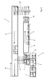
- FIG. 1 shows a schematic representation of an exemplary device according to the invention.
- the delivery circuit 1 is composed of two counter-rotating conveyors 8 and 9 and two translators 12 and 13, which can translate workpieces from one conveyor to another.
- the conveyor 8 runs along a processing machine, not shown, that is, a section of the conveyor 8 forms the processing section. 2
- the conveyor circuit also has means, which are not shown, for changing the orientation of the workpieces between their passes through the processing line 2, it is possible to design the processing line 2 so that only one edge 4 of the workpiece is processed by the processing line for conveying a workpiece , Thereupon, the workpiece passes through the translator 12, the second conveyor 9 and the translator 13, whereupon it again reaches the conveyor 8 and is conveyed once more through the processing section. If the orientation of the workpiece between the conveyances along the processing path 2 is changed, the processing of another edge 4 of the respective workpiece 3 takes place.
- the means for changing the orientation of the workpieces 3 can basically be located at each position of the delivery cycle.
- a removal station not shown, may be provided, which may in principle be located at any point of the delivery circuit 1.
- the conveyor 9 is designed so that it can further promote the workpieces 3 beyond the transfer point with the translator 13, so that a portion of the conveyor 9 no longer belongs to the conveyor circuit 1, but a removal section 14, from which the workpieces can be removed.
- the feeder has a loading station 6 and a sorting station 7.
- the workpieces are grouped according to their dimensions, in the example shown are groups of four workpieces, which are collected in a rectangular grid to so-called images supplied by the feeding station 6 in groups the conveying circuit 1.
- the separation station 11 which singulates the workpieces 3 fed in groups, before they are conveyed and processed individually by the conveyor 8 along the conveying path 2.
- the conveyor 8 is followed by a collecting station 10, in which the separated workpieces 3 are again grouped into groups. These groups are then transferred to the translator 12, conveyed back by the conveyor 9 and fed back to the separation station 11 by the translator 13.
Landscapes
- Life Sciences & Earth Sciences (AREA)
- Engineering & Computer Science (AREA)
- Mechanical Engineering (AREA)
- Wood Science & Technology (AREA)
- Forests & Forestry (AREA)
- Attitude Control For Articles On Conveyors (AREA)
- Feeding Of Workpieces (AREA)
Abstract
Description
Die Erfindung betrifft eine Vorrichtung und ein Verfahren zur Bearbeitung von Kanten plattenförmiger Werkstücke.The invention relates to a device and a method for processing edges of plate-shaped workpieces.
Derartige plattenförmige Werkstücke kommen insbesondere in der Möbelindustrie zum Einsatz. Dort werden insbesondere Holzwerkstoffe aber auch holzhaltige Werkstoffe, wie beispielsweise Spanplatten verarbeitet, wobei plattenförmige Zwischenprodukte, welche an ihren flächigen Seiten in der Regel bereits fertig beschichtet sind, zunächst auf das für die Weiterverarbeitung gewünschte Format geschnitten und dann im Bereich ihrer Schmalseiten bearbeitet werden, worunter insbesondere das Versehen der im Folgenden als Kanten bezeichneten Schmalseiten mit geeigneten Beschichtungen zu verstehen ist.Such plate-shaped workpieces are used in particular in the furniture industry. There, in particular wood-based materials but also wood-containing materials, such as chipboard processed, wherein plate-shaped intermediates, which are already finished coated on their sheet-like pages usually first cut to the desired format for further processing and then edited in the region of their narrow sides, including in particular, the provision of the narrow sides, referred to below as edges, with suitable coatings is to be understood.
Diese Bearbeitung der Kanten der auf das gewünschte Format zurechtgeschnittenen plattenförmigen Werkstücke findet dabei häufig in sogenannten Kantenkreisen statt. Hierunter sind Vorrichtungen zu verstehen, welche einen Förderkreislauf umfassen, in welchem die Werkstücke mehrfach zur Kantenbearbeitung entlang einer Bearbeitungsstrecke förderbar sind. Gemäß dem Stand der Technik werden die Werkstücke einzeln dem Förderkreislauf zugeführt, in diesem solange im Kreislauf gefördert, bis die Bearbeitung sämtlicher zu bearbeitender Kanten des jeweiligen Werkstücks abgeschlossen ist und dann aus dem Förderkreislauf wieder ausgeschleust.This processing of the edges of the cut to the desired format plate-shaped workpieces often takes place in so-called edge circles. This is to be understood as devices which comprise a conveyor cycle in which the workpieces can be conveyed multiple times for edge processing along a processing path. According to the state of the art, the workpieces are supplied individually to the delivery circuit, while being conveyed in the circulation until the processing of all edges of the respective workpiece to be processed has been completed and then discharged from the delivery cycle again.
Nachteilig an bekannten Förderkreisläufen ist jedoch, dass die einzelnen Bearbeitungsaggregate zur Kantenbearbeitung entlang des Förderkreislaufs sowie Fördereinrichtungen, die Bestandteil des Förderkreislaufs sind, plattenförmige Werkstücke mit unterschiedlichen Abmessungen in unterschiedlicher Geschwindigkeit bearbeiten bzw. fördern können. Dabei ist die Abstimmung der einzelnen Komponenten einer derartigen Vorrichtung auf einen optimalen Durchsatz nur eingeschränkt möglich, da in derartigen Vorrichtungen regelmäßig Platten verschiedener Abmessungen bearbeitet werden sollen. D.h. werden die einzelnen Aggregate darauf abgestimmt, Platten einer bestimmten Abmessung derart verarbeiten zu können, dass die Kapazitäten derart aufeinander abgestimmt sind, dass es im Förderkreislauf an keiner Stelle zu einem Engpass bzw. Stau kommt, so trifft diese Abstimmung nicht mehr zu, wenn Werkstücke mit anderen Maßen verarbeitet werden sollen, d.h. es kommt dann, beispielsweise vor einem Bearbeitungsaggregat, zu einem Stau, weil dieses Bearbeitungsaggregat die Werkstücke mit den neuen Abmessungen nicht mehr in der Geschwindigkeit verarbeiten kann wie die Werkstücke mit den alten Abmessungen, die weiteren Bestandteile des Förderkreislaufs jedoch weiterhin die alte Bearbeitungskapazität erreichen.A disadvantage of known conveyor circuits, however, is that the individual processing units for edge processing along the conveyor cycle and conveyors, which are part of the delivery cycle, can edit or promote plate-shaped workpieces with different dimensions at different speeds. In this case, the coordination of the individual components of such a device to an optimum throughput is only possible to a limited extent, since in such devices regularly plates of different dimensions are to be processed. That is, the individual units are tuned to be able to process plates of a certain size so that the capacities are coordinated so that there is no bottleneck or congestion at any point in the delivery cycle, this vote is no longer true when workpieces to be processed with other dimensions, ie it comes then, for example, before a processing unit to a traffic jam, because this processing unit can no longer process the workpieces with the new dimensions in speed as the workpieces with the old dimensions, the other components of the delivery cycle however, continue to reach the old processing capacity.
Der Erfindung liegt daher die Aufgabe zugrunde, eine Vorrichtung und ein Verfahren zur Bearbeitung von Kanten plattenförmiger Werkstücke aufzuzeigen, welches eine gleichmäßige Auslastung aller einzelnen Elementen der Vorrichtung und damit eine optimale Auslastung der gesamten Vorrichtung ermöglicht.The invention is therefore an object of the invention to provide an apparatus and a method for processing edges of plate-shaped workpieces, which allows a uniform utilization of all the individual elements of the device and thus optimal utilization of the entire device.
Die Aufgabe wird gelöst durch eine Vorrichtung und ein Verfahren gemäß den unabhängigen Ansprüchen.The object is achieved by an apparatus and a method according to the independent claims.
Das erfindungsgemäße Verfahren sieht vor, die Maße der Werkstücke vor deren Zuführung in den Förderkreislauf zu erfassen und die Reihenfolge, in der die Werkstücke dem Förderkreislauf zugeführt werden, in Abhängigkeit von den erfassten Maßen der Werkstücke festzulegen. Die erfindungsgemäße Vorrichtung weist hierfür eine Beschickungsvorrichtung auf, die dazu eingerichtet ist, die Reihenfolge, mit der die Werkstücke dem Förderkreislauf zugeführt werden, in Abhängigkeit von den Maßen der Werkstücke festzulegen.The method according to the invention provides for the dimensions of the workpieces before they are fed into the delivery circuit determine and determine the order in which the workpieces are fed to the conveyor cycle, depending on the detected dimensions of the workpieces. For this purpose, the device according to the invention has a charging device which is set up to determine the order in which the workpieces are fed to the delivery circuit as a function of the dimensions of the workpieces.
Durch die Festlegung der Zuführreihenfolge in Abhängigkeit der Maße der Werkstücke ist es möglich, die Beschickungsreihenfolge des Förderkreislaufs so zu wählen, dass eine gleichmäßige Auslastung aller Elemente des Förderkreislaufs und aller an diesem Förderkreislauf vorgesehenen Bearbeitungsvorrichtungen erfolgt.By defining the supply order depending on the dimensions of the workpieces, it is possible to select the feed order of the delivery cycle so that a uniform utilization of all elements of the delivery cycle and all provided on this funding cycle processing devices takes place.
Arbeitet beispielsweise ein Element des Förderkreislaufs derart, dass eine bestimmte Stückzahl pro Zeiteinheit bearbeitet werden kann und ein anderes Element des Förderkreislaufs so, dass eine bestimmte laufende Strecke Kantenlänge pro Zeiteinheit bearbeitet werden kann, so werden die Werkstücke derart zusammengestellt, dass Werkstücke mit kurzen zu bearbeitenden Kanten auf Werkstücke mit langen zu bearbeitenden Kanten folgen und umgekehrt. Auf diese Weise wird verhindert, dass jene Einrichtung, die eine bestimmte Anzahl Werkstücke pro Zeiteinheit bewältigen kann, nicht richtig ausgelastet wird, weil sich Werkstücke mit langen Kanten vor der Einrichtung, welche eine bestimmte Kantenlänge pro Zeiteinheit bearbeiten kann, stauen. Umgekehrt wird verhindert, dass, wenn Werkstücke mit kurzen Kanten in großer Anzahl direkt aufeinanderfolgen, eine mangelnde Auslastung der Einrichtung erfolgt, welche eine bestimmte Kantenlänge pro Zeiteinheit bearbeiten kann, während sich Werkstücke vor einer Einrichtung, welche eine gewisse Stückzahl Werkstücke pro Zeiteinheit bewältigen kann, stauen.If, for example, one element of the conveyor cycle operates such that a certain number of pieces per unit of time can be processed and another element of the conveyor cycle can be processed such that a certain current length of edge per unit time, the workpieces are assembled so that workpieces with short to be machined Follow edges on workpieces with long edges to be machined and vice versa. In this way it is prevented that the device, which can handle a certain number of workpieces per unit time, is not utilized properly, because workpieces with long edges jam in front of the device, which can process a certain edge length per unit time. Conversely, if workpieces with short edges in large numbers directly follow one another, it is prevented that the device is under-utilized, which can process a certain edge length per unit of time, while workpieces are arranged in front of a device, which can handle a certain number of workpieces per unit time, jam.
Neben den Längen der Kanten können auch weitere Maße, so beispielsweise die Dicken der Werkstücke oder deren Fläche berücksichtigt werden.In addition to the lengths of the edges and other dimensions, such as the thickness of the workpieces or their area can be considered.
Vorteilhafterweise ist der Förderkreislauf derart ausgebildet, dass jeweils eine Kante eines Werkstücks bearbeitet wird, wenn dieses entlang einer Bearbeitungsstrecke, also einem Streckenabschnitt des Förderkreislaufs, in dem eine Bearbeitung der Kante durch ein Bearbeitungsaggregat erfolgt, gefördert wird. Um die Bearbeitung aller Werkstückkanten zu ermöglichen, ohne jedoch einer der Zahl der Kanten des Werkstückes entsprechenden Anzahl Bearbeitungsstrecken in einem Förderkreislauf zu bedürfen, ist es sinnvoll, die Orientierung des Werkstücks relativ zur Bearbeitungsstrecke zwischen zwei Förderungen des Werkstücks entlang dieser Bearbeitungsstrecke zu ändern. Auf diese Weise kommen die Bearbeitungsaggregate bei jedem Förderdurchgang an einer anderen Kante des Werkstücks zum Eingriff.Advantageously, the conveyor circuit is designed such that in each case an edge of a workpiece is processed when this is along a processing line, ie a section of the conveyor cycle, in which a processing of the edge is carried out by a processing unit, promoted. In order to enable the machining of all workpiece edges, but without requiring a number of processing sections corresponding to the number of edges of the workpiece, it makes sense to change the orientation of the workpiece relative to the processing path between two conveyances of the workpiece along this processing path. In this way, the processing units come at each conveyor passage at another edge of the workpiece for engagement.
Dabei ist es möglich, auch die Orientierung der Werkstücke während der Beschickung zu berücksichtigen, d.h. die Werkstücke bereits in einer Orientierung dem Förderkreislauf zuzuführen, welche die unterschiedlichen Bearbeitungskapazitäten berücksichtigt. Dies ist z.B. dann sinnvoll, wenn langgestreckte Werkstücke mit jeweils einem Paar langer und einem Paar kurzer Kanten bearbeitet werden sollen. Werden diese dem Förderkreislauf so zugeführt, dass sich jeweils eine der längeren Kanten eines Werkstücks mit einer der kürzeren Kanten des folgenden Werkstücks und umgekehrt abwechselt, so wird bei jeder Förderung einer gewissen Anzahl Werkstücke entlang der Bearbeitungsstrecke ein im Mittel gleichmäßiges Verhältnis zwischen zu bearbeitender Kantenlänge und Stückzahl erreicht, was nicht der Fall wäre, würden zunächst die langen Kanten sämtlicher Werkstücke und dann in einem weiteren Durchlauf des Förderkreislaufs die jeweils kurzen Kanten der einzelnen Werkstücke bearbeitet. Dies hätte zur Folge, dass sich zwischen den beiden Durchläufen des Förderkreislaufs das Verhältnis der zu bearbeitenden Kantenlänge zur Stückzahl der Werkstücke deutlich ändern würde, wodurch es wiederum zur Überlastung der Kapazitäten einzelner Aggregate bei gleichzeitiger Minderauslastung anderer Aggregate kommen würde.It is also possible to take into account the orientation of the workpieces during the loading, ie to feed the workpieces already in an orientation to the conveyor cycle, which takes into account the different processing capacities. This is useful, for example, when elongate workpieces are to be processed, each with a pair of long edges and a pair of short edges. If these are fed to the conveyor circuit such that one of the longer edges of a workpiece alternates with one of the shorter edges of the following workpiece and vice versa, then at each Promoting a certain number of workpieces along the processing line achieved a mean uniform ratio between edge length to be processed and number of pieces, which would not be the case, first the long edges of all workpieces and then processed in a further pass of the conveyor cycle, the respective short edges of the individual workpieces , This would mean that the ratio of the edge length to be machined to the number of workpieces would change significantly between the two passes of the delivery cycle, which in turn would lead to overloading of the capacities of individual units with simultaneous underutilization of other units.
Alternativ zur Zuführung einzelner Werkstücke in den Förderkreislauf durch die Beschickungsvorrichtung ist auch eine gruppenweise Zuführung möglich. Die gruppenweise Zuführung kann beispielsweise unter der Verwendung einer Sortierstation erfolgen, in der die Werkstücke zunächst gruppenweise so zusammengestellt werden, dass die für die Kapazitäten im Förderkreislauf relevanten Maße im Mittel der jeweiligen Gruppe nach Möglichkeit konstant sind, d.h. dass die Zusammenstellung derart erfolgt, dass eine Schwankung der Maße von Gruppenmittel zu Gruppenmittel minimiert wird, also beispielsweise vermieden wird, eine Gruppe nur aus sehr kleinen Werkstücken, also Werkstücken mit einem großen Verhältnis von Stückzahl zu zu bearbeitender Kantenlänge zusammenzustellen.As an alternative to the supply of individual workpieces in the delivery cycle through the feeder, a group-wise supply is possible. The group-wise feeding can take place, for example, by using a sorting station in which the workpieces are first grouped together in such a way that the dimensions relevant for the capacities in the conveying cycle are as constant as possible on average of the respective group, i. that the compilation takes place in such a way that a fluctuation in the dimensions of group means to group means is minimized, for example it is avoided to assemble a group only of very small workpieces, that is to say workpieces with a large ratio of piece number to edge length to be processed.
Die
Der Förderkreislauf 1 setzt sich zusammen aus zwei gegenläufig arbeitenden Förderern 8 und 9 sowie zwei Übersetzern 12 und 13, welche Werkstücke von einem auf den anderen Förderer übersetzen können. Der Förderer 8 läuft dabei entlang einer nicht dargestellten Bearbeitungsmaschine, d.h. ein Teilabschnitt des Förderers 8 bildet die Bearbeitungsstrecke 2.The delivery circuit 1 is composed of two counter-rotating conveyors 8 and 9 and two
Weist der Förderkreislauf weiterhin nicht dargestellte Mittel zur Veränderung der Orientierung der Werkstücke zwischen deren Durchläufen durch die Bearbeitungsstrecke 2 auf, so ist es möglich, die Bearbeitungsstrecke 2 so zu gestalten, dass pro Förderung eines Werkstücks durch die Bearbeitungsstrecke nur eine Kante 4 des Werkstücks bearbeitet wird. Daraufhin durchläuft das Werkstück den Übersetzer 12, den zweiten Förderer 9 und den Übersetzer 13, woraufhin es wieder auf den Förderer 8 gelangt und ein weiteres Mal durch die Bearbeitungsstrecke gefördert wird. Wird dabei die Orientierung des Werkstücks zwischen den Förderungen entlang der Bearbeitungsstrecke 2 geändert, so erfolgt die Bearbeitung einer anderen Kante 4 des jeweiligen Werkstücks 3. Dabei können sich die Mittel zur Änderung der Orientierung der Werkstücke 3 grundsätzlich an jeder Position des Förderkreislaufs befinden.If the conveyor circuit also has means, which are not shown, for changing the orientation of the workpieces between their passes through the processing line 2, it is possible to design the processing line 2 so that only one edge 4 of the workpiece is processed by the processing line for conveying a workpiece , Thereupon, the workpiece passes through the
Sind alle zu bearbeitenden Kanten 4 des jeweiligen Werkstücks 3 nach einer entsprechenden Anzahl Durchläufen durch den Förderkreislauf 1 bearbeitet, so werden die Werkstücke 3 dem Förderkreislauf 1 entnommen. Hierzu kann eine nicht dargestellte Entnahmestation vorgesehen sein, die sich grundsätzlich an jeder Stelle des Förderkreislaufs 1 befinden kann. Im gezeigten Beispiel ist der Förderer 9 so gestaltet, dass er die Werkstücke 3 über den Übergabepunkt mit dem Übersetzer 13 hinaus weiter fördern kann, so dass ein Abschnitt des Förderers 9 nicht mehr zum Förderkreislauf 1 gehört, sondern einen Entnahmeabschnitt 14 darstellt, von dem die Werkstücke entnommen werden können.If all the edges 4 to be machined of the
Die Beschickungsvorrichtung weist eine Beschickungsstation 6 und eine Sortierstation 7 auf. In der Sortierstation werden die Werkstücke entsprechend ihrer Maße gruppenweise zusammengestellt, im gezeigten Beispiel handelt es sich um Gruppen von jeweils vier Werkstücken, die in einem rechteckigen Raster zu sogenannten Bildern zusammengestellt durch die Beschickungsstation 6 gruppenweise dem Förderkreislauf 1 zugeführt werden.The feeder has a loading station 6 and a sorting station 7. In the sorting station, the workpieces are grouped according to their dimensions, in the example shown are groups of four workpieces, which are collected in a rectangular grid to so-called images supplied by the feeding station 6 in groups the conveying circuit 1.
Im Förderkreislauf gelangen sie zunächst in die Vereinzelungsstation 11, welche die in Gruppen zugeführten Werkstücke 3 vereinzelt, bevor diese einzeln durch den Förderer 8 entlang der Förderstrecke 2 gefördert und bearbeitet werden. An den Förderer 8 schließt sich eine Sammelstation 10 an, in welcher die vereinzelten Werkstücke 3 wieder zu Gruppen gruppiert werden. Diese Gruppen werden dann an den Übersetzer 12 übergeben, durch den Förderer 9 zurück gefördert und durch den Übersetzer 13 wieder der Vereinzelungsstation 11 zugeführt.In the delivery cycle, they first pass into the
Claims (10)
dass die Beschickungsvorrichtung (5) dazu eingerichtet ist, die Reihenfolge, mit der die Werkstücke (3) dem Förderkreislauf (1) zugeführt werden, in Abhängigkeit von den Maßen der Werkstücke (3) festzulegen.Device for processing edges (4) of plate-shaped workpieces (3), a conveyor circuit (1), comprising a processing section (2) for processing the edges (4), which is designed such that the workpieces (3) are multiply processed for processing the edges (4) along the processing line (2) are conveyed, and a loading device (5) for supplying the workpieces (3) in the delivery circuit (1), comprising, characterized
in that the loading device (5) is set up to determine the order in which the workpieces (3) are fed to the conveying circuit (1) as a function of the dimensions of the workpieces (3).
dadurch gekennzeichnet,
dass die Beschickungsvorrichtung (5) Mittel zur Erfassung der Maße der Werkstücke (3), insbesondere der Länge der Kanten (4) und/oder der Dicke der Werkstücke (3) umfasst.Device according to claim 1,
characterized,
in that the loading device (5) comprises means for detecting the dimensions of the workpieces (3), in particular the length of the edges (4) and / or the thickness of the workpieces (3).
dadurch gekennzeichnet,
dass der Förderkreislauf (1) derart ausgebildet ist, dass jeweils eine Kante (4) eines jeweiligen Werkstücks (3) während einer Förderung des Werkstücks (3) entlang der Bearbeitungsstrecke (2) bearbeitbar ist.Apparatus according to claim 1 or 2,
characterized,
in that the conveying circuit (1) is designed in such a way that in each case one edge (4) of a respective workpiece (3) can be machined along the processing path (2) during conveying of the workpiece (3).
dadurch gekennzeichnet,
dass der Förderkreislauf (1) eine Einrichtung zur Veränderung der Orientierung eines Werkstücks (3) relativ zur Bearbeitungsstrecke (2) zwischen einer ersten und einer zweiten Förderung des Werkstücks (3) entlang der Bearbeitungsstrecke (2) aufweist.Device according to one of the preceding claims,
characterized,
in that the conveyor circuit (1) has a device for changing the orientation of a workpiece (3) relative to the processing section (2) between a first and a second promotion of the workpiece (3) along the processing path (2).
dadurch gekennzeichnet,
dass die Beschickungsvorrichtung (5) dazu eingerichtet ist, die Werkstücke (3) in Gruppen zusammenzustellen, die dem Förderkreislauf (1) zugeführt werden.Device according to one of the preceding claims,
characterized,
in that the loading device (5) is set up to assemble the workpieces (3) into groups which are fed to the delivery circuit (1).
dass die Maße der Werkstücke (3) vor deren Zuführung in den Förderkreislauf (1) erfasst und die Reihenfolge, in der die Werkstücke (3) dem Förderkreislauf (1) zugeführt werden, in Abhängigkeit von den erfassten Maßen der Werkstücke (3), festgelegt wird.Method for processing edges (4) of plate-shaped workpieces (3), wherein the workpieces (3) are conveyed in a conveyor circuit (1), for processing the edges (4) of the workpieces (3) repeatedly along a processing section (2) and conveyed Delivery cycle (1) are removed after processing, characterized
in that the dimensions of the workpieces (3) are detected before they are fed into the conveyor circuit (1) and the order in which the workpieces (3) are fed to the conveyor circuit (1) is determined as a function of the detected dimensions of the workpieces (3) becomes.
dadurch gekennzeichnet,
dass die Maße die Kantenlängen und/oder Dicken der Werkstücke (3) umfassen.Method according to claim 6,
characterized,
that the dimensions of the edge lengths and / or thicknesses include the workpieces (3).
dadurch gekennzeichnet,
dass bei jeder Förderung eines Werkstücks (3) entlang der Bearbeitungsstrecke (2) jeweils eine Kante (4) des jeweiligen Werkstücks (3) bearbeitet wird.Method according to claim 6 or 7,
characterized,
in that each time a workpiece (3) is conveyed along the processing path (2), one edge (4) of the respective workpiece (3) is processed.
dadurch gekennzeichnet,
dass zwischen zwei Förderungen eines Werkstücks (3) entlang der Bearbeitungsstrecke (2) die Orientierung des Werkstücks (3) derart geändert wird, dass während der beiden Förderungen jeweils unterschiedliche Kanten (4) des Werkstücks (3) bearbeitet werden können.Method according to one of claims 6 to 8,
characterized,
that the orientation of the workpiece (3) is changed in such a manner between two promotions of a workpiece (3) along the processing path (2), that during the two promotions respectively different edges (4) of the workpiece (3) can be edited.
dadurch gekennzeichnet,
dass die Werkstücke (3) entsprechend der festgelegten Reihenfolge in Gruppen zusammengestellt und dem Förderkreislauf (1) Gruppenweise zugeführt werden.Method according to one of claims 6 to 9,
characterized,
in that the workpieces (3) are assembled in groups according to the specified order and supplied to the delivery circuit (1) in groups.
Priority Applications (2)
| Application Number | Priority Date | Filing Date | Title |
|---|---|---|---|
| EP20157283.1A EP3677396A1 (en) | 2013-03-16 | 2014-03-11 | Device and method for machining the edges of flat plate-shaped workpieces |
| PL14000850T PL2777902T3 (en) | 2013-03-16 | 2014-03-11 | Method for machining the edges of flat workpieces |
Applications Claiming Priority (1)
| Application Number | Priority Date | Filing Date | Title |
|---|---|---|---|
| DE102013004648.3A DE102013004648A1 (en) | 2013-03-16 | 2013-03-16 | Apparatus and method for processing edges of plate-shaped workpieces |
Related Child Applications (1)
| Application Number | Title | Priority Date | Filing Date |
|---|---|---|---|
| EP20157283.1A Division EP3677396A1 (en) | 2013-03-16 | 2014-03-11 | Device and method for machining the edges of flat plate-shaped workpieces |
Publications (2)
| Publication Number | Publication Date |
|---|---|
| EP2777902A1 true EP2777902A1 (en) | 2014-09-17 |
| EP2777902B1 EP2777902B1 (en) | 2020-02-19 |
Family
ID=50280106
Family Applications (2)
| Application Number | Title | Priority Date | Filing Date |
|---|---|---|---|
| EP14000850.9A Active EP2777902B1 (en) | 2013-03-16 | 2014-03-11 | Method for machining the edges of flat workpieces |
| EP20157283.1A Pending EP3677396A1 (en) | 2013-03-16 | 2014-03-11 | Device and method for machining the edges of flat plate-shaped workpieces |
Family Applications After (1)
| Application Number | Title | Priority Date | Filing Date |
|---|---|---|---|
| EP20157283.1A Pending EP3677396A1 (en) | 2013-03-16 | 2014-03-11 | Device and method for machining the edges of flat plate-shaped workpieces |
Country Status (4)
| Country | Link |
|---|---|
| EP (2) | EP2777902B1 (en) |
| DE (1) | DE102013004648A1 (en) |
| ES (1) | ES2785314T3 (en) |
| PL (1) | PL2777902T3 (en) |
Cited By (4)
| Publication number | Priority date | Publication date | Assignee | Title |
|---|---|---|---|---|
| EP3037228A1 (en) * | 2014-12-24 | 2016-06-29 | IMA Klessmann GmbH | Device and method for machining plate-shaped workpieces |
| DE102017114203A1 (en) | 2017-03-23 | 2018-09-27 | Foshan Beite Office System Equipment Co., Ltd | Binding method of the bander with an operation of four L-shaped connected machines |
| EP4194166A1 (en) * | 2021-12-02 | 2023-06-14 | HOMAG GmbH | Method for machining continuously moving workpieces |
| EP4205899A1 (en) * | 2022-01-03 | 2023-07-05 | IMA Schelling Deutschland GmbH | Device for machining, in particular panel-shaped, workpieces made of wood or wood substitutes and method for operating such a device |
Citations (1)
| Publication number | Priority date | Publication date | Assignee | Title |
|---|---|---|---|---|
| EP0724939A1 (en) * | 1995-02-04 | 1996-08-07 | Hans Hundegger | Trimming-machine for working workpieces, in particular boards, squared timber and the like |
Family Cites Families (6)
| Publication number | Priority date | Publication date | Assignee | Title |
|---|---|---|---|---|
| FR2689807A1 (en) * | 1992-04-08 | 1993-10-15 | Lyon Flex Ets Marcel Prost Dam | Production line for wooden work pieces such as beams - uses clawed trolley to measure work piece and convey it to various work stations followed by second trolley to complete mfg. process |
| DE9307220U1 (en) * | 1993-05-12 | 1993-09-02 | Ligmatech Maschinenbau GmbH, 09638 Lichtenberg | Device for returning workpieces machined in a machining arrangement from the output side of the machining arrangement to its loading side |
| US7073422B2 (en) * | 2002-08-20 | 2006-07-11 | Precision Automation, Inc. | Linkage device for linear positioning apparatus |
| DE102007035743B4 (en) * | 2007-07-31 | 2009-06-18 | Priess, Horstmann & Co. Maschinenbau Gmbh & Co. Kg | Processing station for processing plate-shaped workpieces |
| DE102008061766B4 (en) * | 2008-12-14 | 2018-12-06 | Grecon Dimter Holzoptimierung Nord Gmbh & Co. Kg | Method for the production of components made by finger jointing and apparatus for carrying out this method |
| DE202009006536U1 (en) * | 2009-05-05 | 2010-09-23 | Bargstedt Handlingsysteme Gmbh | processing plant |
-
2013
- 2013-03-16 DE DE102013004648.3A patent/DE102013004648A1/en not_active Withdrawn
-
2014
- 2014-03-11 ES ES14000850T patent/ES2785314T3/en active Active
- 2014-03-11 EP EP14000850.9A patent/EP2777902B1/en active Active
- 2014-03-11 PL PL14000850T patent/PL2777902T3/en unknown
- 2014-03-11 EP EP20157283.1A patent/EP3677396A1/en active Pending
Patent Citations (1)
| Publication number | Priority date | Publication date | Assignee | Title |
|---|---|---|---|---|
| EP0724939A1 (en) * | 1995-02-04 | 1996-08-07 | Hans Hundegger | Trimming-machine for working workpieces, in particular boards, squared timber and the like |
Cited By (5)
| Publication number | Priority date | Publication date | Assignee | Title |
|---|---|---|---|---|
| EP3037228A1 (en) * | 2014-12-24 | 2016-06-29 | IMA Klessmann GmbH | Device and method for machining plate-shaped workpieces |
| DE102017114203A1 (en) | 2017-03-23 | 2018-09-27 | Foshan Beite Office System Equipment Co., Ltd | Binding method of the bander with an operation of four L-shaped connected machines |
| DE102017114203B4 (en) * | 2017-03-23 | 2019-01-17 | Foshan Beite Office System Equipment Co., Ltd | Binding method of the bander with an operation of four L-shaped connected machines |
| EP4194166A1 (en) * | 2021-12-02 | 2023-06-14 | HOMAG GmbH | Method for machining continuously moving workpieces |
| EP4205899A1 (en) * | 2022-01-03 | 2023-07-05 | IMA Schelling Deutschland GmbH | Device for machining, in particular panel-shaped, workpieces made of wood or wood substitutes and method for operating such a device |
Also Published As
| Publication number | Publication date |
|---|---|
| PL2777902T3 (en) | 2020-07-27 |
| EP2777902B1 (en) | 2020-02-19 |
| EP3677396A1 (en) | 2020-07-08 |
| DE102013004648A1 (en) | 2014-09-18 |
| ES2785314T3 (en) | 2020-10-06 |
Similar Documents
| Publication | Publication Date | Title |
|---|---|---|
| EP2777902B1 (en) | Method for machining the edges of flat workpieces | |
| DE102013206138A1 (en) | Apparatus for completing a format set of products | |
| AT510304A1 (en) | METHOD OF CUTTING AT LEAST ONE PLATE | |
| DE102007059303A1 (en) | Processing plant for linking processing station at e.g. hand work place, has separation devices i.e. slider, transporting carriers from outer to inner belt and/or from inner to outer belt, and provided before stations in conveying direction | |
| EP1302418A1 (en) | Apparatus and method for feeding sequentially objects during their processing | |
| DE202009006536U1 (en) | processing plant | |
| EP3090848B1 (en) | Method for machining flat workpieces | |
| DE102016014682A1 (en) | Method and device for dividing plate-shaped workpieces | |
| EP1954615B1 (en) | Method of, and apparatus for, optionally processing printed products | |
| EP2527112B1 (en) | Processing device | |
| DE3300351C2 (en) | Device for dividing panels, in particular chipboard | |
| AT516092A1 (en) | Apparatus and method for transporting tubular bag bodies | |
| WO2018065227A1 (en) | Facility for sorting piece goods with dosing device | |
| EP1948541B1 (en) | Continuous conveying apparatus and method of continuously conveying plate-like workpieces | |
| EP2982622B1 (en) | Device for distributing a stream of products | |
| EP2949439B1 (en) | Processing device and processing method | |
| EP2631204B1 (en) | Supply apparatus for conveying products | |
| EP3415463B1 (en) | Arrangement of sections of a string of springs for the manufacture of a spring core | |
| EP2570042B1 (en) | Composite filter production module | |
| EP2452904B1 (en) | Device for transporting stacks of documents, in particular for security-relevant documents, to packaging stations | |
| EP3150344B1 (en) | Alignment device for aligning workpieces and processing machine | |
| DE60011830T2 (en) | Conveying device for forming and conveying groups of objects | |
| EP1076021B1 (en) | Method and device for combining streams of articles | |
| EP1516546B1 (en) | Apparatus and method for transferring rod-like articles | |
| DE102007041167A1 (en) | Device for turning products |
Legal Events
| Date | Code | Title | Description |
|---|---|---|---|
| PUAI | Public reference made under article 153(3) epc to a published international application that has entered the european phase |
Free format text: ORIGINAL CODE: 0009012 |
|
| 17P | Request for examination filed |
Effective date: 20140311 |
|
| AK | Designated contracting states |
Kind code of ref document: A1 Designated state(s): AL AT BE BG CH CY CZ DE DK EE ES FI FR GB GR HR HU IE IS IT LI LT LU LV MC MK MT NL NO PL PT RO RS SE SI SK SM TR |
|
| AX | Request for extension of the european patent |
Extension state: BA ME |
|
| R17P | Request for examination filed (corrected) |
Effective date: 20150304 |
|
| RBV | Designated contracting states (corrected) |
Designated state(s): AL AT BE BG CH CY CZ DE DK EE ES FI FR GB GR HR HU IE IS IT LI LT LU LV MC MK MT NL NO PL PT RO RS SE SI SK SM TR |
|
| 17Q | First examination report despatched |
Effective date: 20151216 |
|
| STAA | Information on the status of an ep patent application or granted ep patent |
Free format text: STATUS: EXAMINATION IS IN PROGRESS |
|
| GRAP | Despatch of communication of intention to grant a patent |
Free format text: ORIGINAL CODE: EPIDOSNIGR1 |
|
| STAA | Information on the status of an ep patent application or granted ep patent |
Free format text: STATUS: GRANT OF PATENT IS INTENDED |
|
| INTG | Intention to grant announced |
Effective date: 20190816 |
|
| GRAS | Grant fee paid |
Free format text: ORIGINAL CODE: EPIDOSNIGR3 |
|
| GRAJ | Information related to disapproval of communication of intention to grant by the applicant or resumption of examination proceedings by the epo deleted |
Free format text: ORIGINAL CODE: EPIDOSDIGR1 |
|
| GRAL | Information related to payment of fee for publishing/printing deleted |
Free format text: ORIGINAL CODE: EPIDOSDIGR3 |
|
| STAA | Information on the status of an ep patent application or granted ep patent |
Free format text: STATUS: EXAMINATION IS IN PROGRESS |
|
| RAP1 | Party data changed (applicant data changed or rights of an application transferred) |
Owner name: IMA SCHELLING DEUTSCHLAND GMBH |
|
| INTC | Intention to grant announced (deleted) | ||
| GRAP | Despatch of communication of intention to grant a patent |
Free format text: ORIGINAL CODE: EPIDOSNIGR1 |
|
| STAA | Information on the status of an ep patent application or granted ep patent |
Free format text: STATUS: GRANT OF PATENT IS INTENDED |
|
| GRAA | (expected) grant |
Free format text: ORIGINAL CODE: 0009210 |
|
| STAA | Information on the status of an ep patent application or granted ep patent |
Free format text: STATUS: THE PATENT HAS BEEN GRANTED |
|
| INTG | Intention to grant announced |
Effective date: 20200107 |
|
| AK | Designated contracting states |
Kind code of ref document: B1 Designated state(s): AL AT BE BG CH CY CZ DE DK EE ES FI FR GB GR HR HU IE IS IT LI LT LU LV MC MK MT NL NO PL PT RO RS SE SI SK SM TR |
|
| REG | Reference to a national code |
Ref country code: CH Ref legal event code: EP |
|
| REG | Reference to a national code |
Ref country code: DE Ref legal event code: R096 Ref document number: 502014013622 Country of ref document: DE |
|
| REG | Reference to a national code |
Ref country code: AT Ref legal event code: REF Ref document number: 1234416 Country of ref document: AT Kind code of ref document: T Effective date: 20200315 |
|
| REG | Reference to a national code |
Ref country code: IE Ref legal event code: FG4D Free format text: LANGUAGE OF EP DOCUMENT: GERMAN |
|
| REG | Reference to a national code |
Ref country code: NL Ref legal event code: FP |
|
| PG25 | Lapsed in a contracting state [announced via postgrant information from national office to epo] |
Ref country code: NO Free format text: LAPSE BECAUSE OF FAILURE TO SUBMIT A TRANSLATION OF THE DESCRIPTION OR TO PAY THE FEE WITHIN THE PRESCRIBED TIME-LIMIT Effective date: 20200519 Ref country code: RS Free format text: LAPSE BECAUSE OF FAILURE TO SUBMIT A TRANSLATION OF THE DESCRIPTION OR TO PAY THE FEE WITHIN THE PRESCRIBED TIME-LIMIT Effective date: 20200219 Ref country code: FI Free format text: LAPSE BECAUSE OF FAILURE TO SUBMIT A TRANSLATION OF THE DESCRIPTION OR TO PAY THE FEE WITHIN THE PRESCRIBED TIME-LIMIT Effective date: 20200219 |
|
| REG | Reference to a national code |
Ref country code: LT Ref legal event code: MG4D |
|
| PG25 | Lapsed in a contracting state [announced via postgrant information from national office to epo] |
Ref country code: LV Free format text: LAPSE BECAUSE OF FAILURE TO SUBMIT A TRANSLATION OF THE DESCRIPTION OR TO PAY THE FEE WITHIN THE PRESCRIBED TIME-LIMIT Effective date: 20200219 Ref country code: SE Free format text: LAPSE BECAUSE OF FAILURE TO SUBMIT A TRANSLATION OF THE DESCRIPTION OR TO PAY THE FEE WITHIN THE PRESCRIBED TIME-LIMIT Effective date: 20200219 Ref country code: IS Free format text: LAPSE BECAUSE OF FAILURE TO SUBMIT A TRANSLATION OF THE DESCRIPTION OR TO PAY THE FEE WITHIN THE PRESCRIBED TIME-LIMIT Effective date: 20200619 Ref country code: BG Free format text: LAPSE BECAUSE OF FAILURE TO SUBMIT A TRANSLATION OF THE DESCRIPTION OR TO PAY THE FEE WITHIN THE PRESCRIBED TIME-LIMIT Effective date: 20200519 Ref country code: HR Free format text: LAPSE BECAUSE OF FAILURE TO SUBMIT A TRANSLATION OF THE DESCRIPTION OR TO PAY THE FEE WITHIN THE PRESCRIBED TIME-LIMIT Effective date: 20200219 Ref country code: GR Free format text: LAPSE BECAUSE OF FAILURE TO SUBMIT A TRANSLATION OF THE DESCRIPTION OR TO PAY THE FEE WITHIN THE PRESCRIBED TIME-LIMIT Effective date: 20200520 |
|
| REG | Reference to a national code |
Ref country code: ES Ref legal event code: FG2A Ref document number: 2785314 Country of ref document: ES Kind code of ref document: T3 Effective date: 20201006 |
|
| PG25 | Lapsed in a contracting state [announced via postgrant information from national office to epo] |
Ref country code: SK Free format text: LAPSE BECAUSE OF FAILURE TO SUBMIT A TRANSLATION OF THE DESCRIPTION OR TO PAY THE FEE WITHIN THE PRESCRIBED TIME-LIMIT Effective date: 20200219 Ref country code: RO Free format text: LAPSE BECAUSE OF FAILURE TO SUBMIT A TRANSLATION OF THE DESCRIPTION OR TO PAY THE FEE WITHIN THE PRESCRIBED TIME-LIMIT Effective date: 20200219 Ref country code: CZ Free format text: LAPSE BECAUSE OF FAILURE TO SUBMIT A TRANSLATION OF THE DESCRIPTION OR TO PAY THE FEE WITHIN THE PRESCRIBED TIME-LIMIT Effective date: 20200219 Ref country code: DK Free format text: LAPSE BECAUSE OF FAILURE TO SUBMIT A TRANSLATION OF THE DESCRIPTION OR TO PAY THE FEE WITHIN THE PRESCRIBED TIME-LIMIT Effective date: 20200219 Ref country code: SM Free format text: LAPSE BECAUSE OF FAILURE TO SUBMIT A TRANSLATION OF THE DESCRIPTION OR TO PAY THE FEE WITHIN THE PRESCRIBED TIME-LIMIT Effective date: 20200219 Ref country code: PT Free format text: LAPSE BECAUSE OF FAILURE TO SUBMIT A TRANSLATION OF THE DESCRIPTION OR TO PAY THE FEE WITHIN THE PRESCRIBED TIME-LIMIT Effective date: 20200712 Ref country code: LT Free format text: LAPSE BECAUSE OF FAILURE TO SUBMIT A TRANSLATION OF THE DESCRIPTION OR TO PAY THE FEE WITHIN THE PRESCRIBED TIME-LIMIT Effective date: 20200219 Ref country code: EE Free format text: LAPSE BECAUSE OF FAILURE TO SUBMIT A TRANSLATION OF THE DESCRIPTION OR TO PAY THE FEE WITHIN THE PRESCRIBED TIME-LIMIT Effective date: 20200219 |
|
| REG | Reference to a national code |
Ref country code: CH Ref legal event code: PL |
|
| REG | Reference to a national code |
Ref country code: DE Ref legal event code: R097 Ref document number: 502014013622 Country of ref document: DE |
|
| PG25 | Lapsed in a contracting state [announced via postgrant information from national office to epo] |
Ref country code: MC Free format text: LAPSE BECAUSE OF FAILURE TO SUBMIT A TRANSLATION OF THE DESCRIPTION OR TO PAY THE FEE WITHIN THE PRESCRIBED TIME-LIMIT Effective date: 20200219 |
|
| PLBE | No opposition filed within time limit |
Free format text: ORIGINAL CODE: 0009261 |
|
| STAA | Information on the status of an ep patent application or granted ep patent |
Free format text: STATUS: NO OPPOSITION FILED WITHIN TIME LIMIT |
|
| PG25 | Lapsed in a contracting state [announced via postgrant information from national office to epo] |
Ref country code: LU Free format text: LAPSE BECAUSE OF NON-PAYMENT OF DUE FEES Effective date: 20200311 |
|
| 26N | No opposition filed |
Effective date: 20201120 |
|
| PG25 | Lapsed in a contracting state [announced via postgrant information from national office to epo] |
Ref country code: CH Free format text: LAPSE BECAUSE OF NON-PAYMENT OF DUE FEES Effective date: 20200331 Ref country code: IE Free format text: LAPSE BECAUSE OF NON-PAYMENT OF DUE FEES Effective date: 20200311 Ref country code: LI Free format text: LAPSE BECAUSE OF NON-PAYMENT OF DUE FEES Effective date: 20200331 |
|
| PG25 | Lapsed in a contracting state [announced via postgrant information from national office to epo] |
Ref country code: SI Free format text: LAPSE BECAUSE OF FAILURE TO SUBMIT A TRANSLATION OF THE DESCRIPTION OR TO PAY THE FEE WITHIN THE PRESCRIBED TIME-LIMIT Effective date: 20200219 |
|
| REG | Reference to a national code |
Ref country code: AT Ref legal event code: MM01 Ref document number: 1234416 Country of ref document: AT Kind code of ref document: T Effective date: 20200311 |
|
| PG25 | Lapsed in a contracting state [announced via postgrant information from national office to epo] |
Ref country code: AT Free format text: LAPSE BECAUSE OF NON-PAYMENT OF DUE FEES Effective date: 20200311 |
|
| PG25 | Lapsed in a contracting state [announced via postgrant information from national office to epo] |
Ref country code: TR Free format text: LAPSE BECAUSE OF FAILURE TO SUBMIT A TRANSLATION OF THE DESCRIPTION OR TO PAY THE FEE WITHIN THE PRESCRIBED TIME-LIMIT Effective date: 20200219 Ref country code: MT Free format text: LAPSE BECAUSE OF FAILURE TO SUBMIT A TRANSLATION OF THE DESCRIPTION OR TO PAY THE FEE WITHIN THE PRESCRIBED TIME-LIMIT Effective date: 20200219 Ref country code: CY Free format text: LAPSE BECAUSE OF FAILURE TO SUBMIT A TRANSLATION OF THE DESCRIPTION OR TO PAY THE FEE WITHIN THE PRESCRIBED TIME-LIMIT Effective date: 20200219 |
|
| PG25 | Lapsed in a contracting state [announced via postgrant information from national office to epo] |
Ref country code: MK Free format text: LAPSE BECAUSE OF FAILURE TO SUBMIT A TRANSLATION OF THE DESCRIPTION OR TO PAY THE FEE WITHIN THE PRESCRIBED TIME-LIMIT Effective date: 20200219 Ref country code: AL Free format text: LAPSE BECAUSE OF FAILURE TO SUBMIT A TRANSLATION OF THE DESCRIPTION OR TO PAY THE FEE WITHIN THE PRESCRIBED TIME-LIMIT Effective date: 20200219 |
|
| P01 | Opt-out of the competence of the unified patent court (upc) registered |
Effective date: 20230517 |
|
| PGFP | Annual fee paid to national office [announced via postgrant information from national office to epo] |
Ref country code: NL Payment date: 20240319 Year of fee payment: 11 |
|
| PGFP | Annual fee paid to national office [announced via postgrant information from national office to epo] |
Ref country code: GB Payment date: 20240322 Year of fee payment: 11 |
|
| PGFP | Annual fee paid to national office [announced via postgrant information from national office to epo] |
Ref country code: PL Payment date: 20240229 Year of fee payment: 11 Ref country code: IT Payment date: 20240322 Year of fee payment: 11 Ref country code: FR Payment date: 20240320 Year of fee payment: 11 Ref country code: BE Payment date: 20240319 Year of fee payment: 11 |
|
| PGFP | Annual fee paid to national office [announced via postgrant information from national office to epo] |
Ref country code: DE Payment date: 20240408 Year of fee payment: 11 |
|
| PGFP | Annual fee paid to national office [announced via postgrant information from national office to epo] |
Ref country code: ES Payment date: 20240417 Year of fee payment: 11 |