EP2777813A2 - Pulverizer monitoring - Google Patents
Pulverizer monitoring Download PDFInfo
- Publication number
- EP2777813A2 EP2777813A2 EP14159360.8A EP14159360A EP2777813A2 EP 2777813 A2 EP2777813 A2 EP 2777813A2 EP 14159360 A EP14159360 A EP 14159360A EP 2777813 A2 EP2777813 A2 EP 2777813A2
- Authority
- EP
- European Patent Office
- Prior art keywords
- pulverizer
- heat
- air
- combustion
- coal
- Prior art date
- Legal status (The legal status is an assumption and is not a legal conclusion. Google has not performed a legal analysis and makes no representation as to the accuracy of the status listed.)
- Granted
Links
Images


Classifications
-
- B—PERFORMING OPERATIONS; TRANSPORTING
- B02—CRUSHING, PULVERISING, OR DISINTEGRATING; PREPARATORY TREATMENT OF GRAIN FOR MILLING
- B02C—CRUSHING, PULVERISING, OR DISINTEGRATING IN GENERAL; MILLING GRAIN
- B02C23/00—Auxiliary methods or auxiliary devices or accessories specially adapted for crushing or disintegrating not provided for in preceding groups or not specially adapted to apparatus covered by a single preceding group
- B02C23/04—Safety devices
-
- B—PERFORMING OPERATIONS; TRANSPORTING
- B02—CRUSHING, PULVERISING, OR DISINTEGRATING; PREPARATORY TREATMENT OF GRAIN FOR MILLING
- B02C—CRUSHING, PULVERISING, OR DISINTEGRATING IN GENERAL; MILLING GRAIN
- B02C15/00—Disintegrating by milling members in the form of rollers or balls co-operating with rings or discs
-
- B—PERFORMING OPERATIONS; TRANSPORTING
- B02—CRUSHING, PULVERISING, OR DISINTEGRATING; PREPARATORY TREATMENT OF GRAIN FOR MILLING
- B02C—CRUSHING, PULVERISING, OR DISINTEGRATING IN GENERAL; MILLING GRAIN
- B02C15/00—Disintegrating by milling members in the form of rollers or balls co-operating with rings or discs
- B02C15/04—Mills with pressed pendularly-mounted rollers, e.g. spring pressed
-
- B—PERFORMING OPERATIONS; TRANSPORTING
- B02—CRUSHING, PULVERISING, OR DISINTEGRATING; PREPARATORY TREATMENT OF GRAIN FOR MILLING
- B02C—CRUSHING, PULVERISING, OR DISINTEGRATING IN GENERAL; MILLING GRAIN
- B02C25/00—Control arrangements specially adapted for crushing or disintegrating
-
- F—MECHANICAL ENGINEERING; LIGHTING; HEATING; WEAPONS; BLASTING
- F23—COMBUSTION APPARATUS; COMBUSTION PROCESSES
- F23K—FEEDING FUEL TO COMBUSTION APPARATUS
- F23K1/00—Preparation of lump or pulverulent fuel in readiness for delivery to combustion apparatus
-
- F—MECHANICAL ENGINEERING; LIGHTING; HEATING; WEAPONS; BLASTING
- F23—COMBUSTION APPARATUS; COMBUSTION PROCESSES
- F23K—FEEDING FUEL TO COMBUSTION APPARATUS
- F23K2201/00—Pretreatment of solid fuel
- F23K2201/10—Pulverizing
-
- F—MECHANICAL ENGINEERING; LIGHTING; HEATING; WEAPONS; BLASTING
- F23—COMBUSTION APPARATUS; COMBUSTION PROCESSES
- F23K—FEEDING FUEL TO COMBUSTION APPARATUS
- F23K2201/00—Pretreatment of solid fuel
- F23K2201/20—Drying
Definitions
- Embodiments of the invention are directed to monitoring pulverizers and in particular to detecting a combustion-related condition in a pulverizer based on calculating a heat balance of the pulverizer.
- Coal is used as a fuel in many power plants. Before the coal is introduced into the power plant it typically undergoes a pulverization process to reduce the size of the coal from relatively coarse chunks to a fine powder. This is done to increase the reactivity of the coal by increasing the effective surface area, to reduce surface moisture on the coal, and to make transportation of the coal into the furnace forming part of the power plant easier.
- a system for detecting a combustion-related condition in a pulverizer includes a pulverizer configured to receive coal chunks via an inlet, to grind the coal chunks into coal powder and to output the coal powder via an outlet.
- the system includes sensors configured to detect heat input characteristics supplied to the pulverizer and heat output characteristics emitted from the pulverizer.
- the system also includes a controller configured to determine, based on signals from the sensors, whether a combustion-related condition exists in the pulverizer based on a heat balance function including the heat input characteristics and the heat output characteristics.
- a method for detecting a combustion-related condition in a pulverizer includes measuring, with sensors, input heat characteristics of a pulverizer and output heat characteristics of the pulverizer. The method also includes detecting a combustion-related condition in the pulverizer by performing a heat balance operation including the input heat characteristics and the output heat characteristics.
- a pulverizer control system comprised a processor configured to receive as inputs sensor signals corresponding to input heat characteristics of a pulverizer and output heat characteristics of the pulverizer, to determine whether a combustion-related condition exists in the pulverizer based on a heat balance equation including the input heat characteristics and the output heat characteristics, and to perform at least one of generating a signal indicating that a combustion-related condition exists in the pulverizer or controlling the pulverizer to take corrective action based on determining that the combustion-related condition exists in the pulverizer.
- FIG. 1 illustrates a pulverizer system 100 according to an embodiment of the invention.
- the system 100 includes a pulverizer 110 and pulverizer control system 130.
- the pulverizer 110 includes a housing 111.
- a drive assembly 117 is positioned in the housing 111.
- the drive assembly 117 includes one or more of a motor, gear box or gear system, or any other drive members.
- the drive assembly 117 rotates a pedestal 116 on which a coal grinding bowl 115 is mounted.
- One or more roll assemblies 119 are positioned in close proximity to the rotating coal grinding bowl 115. For example, in one embodiment there are three roll assemblies 119 positioned equidistantly approximately one hundred twenty degrees apart.
- Each of the roll assemblies is supported by a support assembly 120, which includes, for example, a support arm 121 and spring assembly 122.
- a support assembly 120 which includes, for example, a support arm 121 and spring assembly 122.
- the roll assembly 119 rotates together with the rotation of the coal grinding bowl 115 and the spring 122 provides biasing force of the roll assembly 119 towards the coal grinding bowl 115.
- a coal feed inlet 114 also referred to as a coal chunk inlet, coal inlet or inlet 114, extends into the housing 111 to allow coal chunks 141 to be inserted into the coal grinding bowl 115 in the housing 111. Drying and transport air is provided from an air duct 118 into the housing 111 which prevents ground coal powder 142 from falling down below the bowl and to direct the ground coal powder 142 up and away from the coal grinding bowl 115 towards a collection chute 112 and out a coal powder outlet 113.
- one or more additional air inlets may be provided to direct seal air flows into the housing 111, which keep the coal 141 and 142 from entering components such as bearings, gears and other moveable components under the bowl 115. From the coal powder outlet 113 the coal powder may be provided to a power generation system to burn the coal powder to generate electrical power, heat or any other type of power.
- sensors 123a to 123f are positioned at multiple locations around the pulverizer 110 to detect characteristics of the pulverizer 110.
- the sensors 123a to 123f are configured to detect characteristics of the pulverizer 110 related to a heat balance algorithm or equation that represents heat sources supplied to the pulverizer 110 and heat emitted by the pulverizer 110.
- a sensor 123a is illustrated as being located near the air duct 118, also referred to as a drying and transport air inlet 118.
- the sensor 123a may detect the temperature of the drying and transport air or the humidity of the drying and transport air, for example.
- the sensor 123b is illustrated as being next to the housing 111.
- the sensor 123b may detect the temperature of the housing 111 to determine a convection heat of the housing 111.
- the sensor 123c is illustrated as being farther from the housing 111 than the sensor 123b.
- the sensor 123c may detect a temperature of air farther from the housing 111 to detect heat radiation of the pulverizer 110.
- Sensor 123d is illustrated as being near a coal powder outlet 113 of the pulverizer 110.
- the sensor 123d may detect the temperature of the air and coal powder emitted from the outlet 113 or a humidity of the air or coal powder emitted from the outlet 113.
- the sensor 123e is illustrated as being located near the coal chunk inlet 114 of the pulverizer 110.
- the sensor 123e may detect a temperature of air provided into the inlet 114.
- the sensor 123f may detect a temperature of heat generated by the grinding of coal in the coal grinding bowl 115.
- embodiments of the invention encompass any configuration of sensors to determine a heat balance equation or algorithm of the pulverizer 110.
- the sensors 123a, 123d and 123e may measure a flow of air or solids.
- Embodiments of the invention also encompass pulverizers having additional sensors including vibration sensors, load sensors or any other sensors.
- the sensors 123a to 123f detect heat characteristics, humidity characteristics and mass characteristics of air and coal into and out from the pulverizer 110, as well as inside the pulverizer 110.
- measured characteristics include a primary air temperature of air input via the coal chunk inlet 114, an air/fuel ratio of air and coal chunks 141 input via the coal chunk inlet 114, a fuel burn rate of coal powder 142 in a combustion system downstream from the coal powder outlet 113, coal inlet 114 temperature and moisture of air entering the inlet 114 or the outlet 113.
- Other examples of measured characteristics include the moisture of coal chunks 141 entering the pulverizer 110, moisture of coal powder 142 exiting the pulverizer 110, and a temperature at the coal powder outlet 113.
- Other examples of measured characteristics include a drying and transport air source temperature at the inlet 118, a drying and transport air flow, a seal air flow temperature and a seal air flow.
- the pulverizer control system 130 monitors and controls operation of the pulverizer 110.
- the monitoring system 131 may include processing circuitry that receives data from the sensors 123a to 123e and controls the drive assembly 117 via the motor control system 133 according to the sensor data as well as user inputs or control data from systems external to the pulverizer control system 130.
- a combustion detection system 132 receives as inputs the sensor data corresponding to heat, humidity and flow data, for example, and generates a heat balance algorithm based on the received sensor data, or feeds the received sensor data into a predetermined heat balance algorithm. If a predetermined imbalance or characteristic is detected in the heat balance algorithm, the combustion detection system 132 determines that there is a combustion-related condition in the housing 111.
- the combustion detection system 132 may generate a warning or notice to a user that there is a combustion-related condition, or the combustion detection system 132 may send control signals to the motor control system 133 and the intake/output control system 134 to automatically control the rotation of the drive assembly 117, to halt air inflow via the air inlet 118, to halt coal chunk 141 input via the coal chunk inlet 114 and to halt coal powder output from the coal powder outlet 113.
- combustion-related condition refers to combustion, such as smoldering or flame and to conditions identified as leading to combustion and being precursors of combustion in a pulverizer 110.
- the combustion detection system 132 detects conditions corresponding to an existing flame, such as an imbalance in a heat balance equation above a threshold corresponding to a flame, and the combustion detection system 132 detects combustion-related conditions that lead to flames in the pulverizer 110, such as high humidity levels at the outlets 113 of the pulverizer 110, the pulverizer 110 operating at a threshold coal-flow level that may lead to overflow of coal into the drive assembly 117 or any other combustion-related condition.
- m mass flow of one or more of air, water vapor and coal
- h enthalpy of the air, water vapor, and/or coal
- Q energy flux, or change in energy.
- to calculate the heat balance the following are measured: dry air entering the pulverizer 110 via the inlet 114; water vapor in the air stream of the inlet 114, dry air of the drying and transport air stream at the inlet 118 and thermal energy contributed to the pulverizer 110 as a function of the grinding process.
- ambient air from the coal chunk inlet 114 may infiltrate the drive assembly 117 components to replace seal air.
- the inlet air provided via the mill inlet duct 114, or coal chunk inlet 114 is drawn into the mill inlet duct from external sources. At least a portion of the air may be passed through a heat exchanger to raise its energy level of the air.
- the remainder of the mill inlet air is bypassed around the air heater and reintroduced as tempering air upstream of the mill inlet duct 114.
- Dampers on both a hot air stream and a tempering air stream control the total quantity of air to the mill while the relative quantities contributed by each is controlled based on the temperature measured at the mill outlet. The quantity and temperature of the air reaching the mill inlet duct 114 are measured so that their respective values are known.
- the humidity ratio of air entering the inlet 114 and exiting the outlet 113 is measured, and the mass flow of water in the incoming air stream to the inlet 114 is determined as well as the mass flow of dry air in the incoming air stream to the inlet 114.
- the humidity of air entering the inlet 118 may also be added to the air entering the inlet 114 in the humidity ratio.
- moisture evaporated from the surface of the coal may be measured by measuring outlet humidity (and based on the humidity ratio), the coal passing through the pulverizer 110 may be measured, such as by measuring the flow of coal chunks 141 into the pulverizer 110, and losses through the housing 111 may be measured, such as by temperature sensors 123b and 123c.
- the pulverizer control system 130 may include any one computer or multiple computers interconnected via a network to monitor and control the pulverizer 110.
- the pulverizer control system 130 may include one or more processors and supporting logic and other circuitry, as well as memory and other computer-readable media that store computer programs to control operation of the pulverizer 110, to receive and analyze sensor signals and to detect fires in the pulverizer 110.
- Components of the pulverizer control system 130 may be connected to each other and to the pulverizer 110 via wires or wirelessly.
- the pulverizer control system 130 and the combustion detection system 132 may detect conditions that may lead to fires prior to the fire being detected in the pulverizer 110.
- the monitoring system 131 may detect a high humidity level at the outlet 113.
- the high humidity levels may lead to clumping of coal particles, which may lead to clogging of the outlet 113 or junctions and pathways downstream of the outlet 113, which may lead to fires.
- the pulverizer control system 130 may then generate a signal or message to warn of the humidity levels or potential fire, or may control the pulverizer 110 or external air supply systems to address the problem.
- the pulverizer control system 130 may detect a flow of coal chunks 141 that is at a predetermined threshold corresponding to coal chunks 141 potentially falling out of the bowl 115 and into the drive system 117, which may in turn lead to fires.
- the pulverizer control system 130 may generate a warning or control the pulverizer 110 or external coal supply systems to address the fire to reduce the flow of coal into the pulverizer 110. While examples of preemptive fire-condition detection have been provided, embodiments of the invention encompass using sensors to detect any condition indicating a potential for fires and combustion in the pulverizer 110.
- FIG. 2 is a block diagram illustrating a heat balance calculation according to an embodiment of the invention.
- the heat balance calculation of a pulverizer 200 is calculated by measuring heat, humidity, mass and flow characteristics of air and coal entering and leaving the pulverizer 200, as well as heat generated by a grinding process in the pulverizer 200.
- the heat balance calculation also includes measuring convection and radiation of the pulverizer 200.
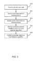
- FIG. 3 illustrates a flowchart of a method according to an embodiment of the invention.
- air and raw coal, or coal chunks are provided to a pulverizer.
- the air is provided via an inlet that receives the coal chunks and supplies the coal chunks to a grinding bowl to be ground into coal powder.
- Air may also be provided from an inlet below the grinding bowl. This air, called drying and transport air, may be heated air that flows upward around the grinding bowl and lifts the coal powder towards an outlet while drying the coal.
- the coal powder may then be used in any process, such as a combustion process to generate heat or power.
- Input heat balance characteristics of the pulverizer are detected. Input heat balance characteristics include the temperature, humidity and flow rate of air entering the pulverizer with coal chunks and the temperature, humidity and flow rate of air entering the pulverizer from below the grinding bowl. Another input heat balance characteristic is the thermal energy contributed to the pulverizer as a function of the grinding process.
- Output heat balance characteristics are sensed.
- Output heat balance characteristics include the temperature, humidity and flow rate of air leaving the pulverizer via an outlet, such as the outlet from which coal powder leaves the pulverizer.
- Other output heat balance characteristics include convection and radiation energy of the pulverizer.
- a combustion-related condition is detected based on applying the input heat balance characteristics and output heat balance characteristics in a heat balance algorithm.
- the input and output heat balance characteristics are compared with each other, and a difference is compared to a threshold value.
- the threshold value may be selected to correspond to a value at which a fire is likely in the pulverizer.
- the threshold value corresponds to a difference, such as five percent, between the heat input characteristics and heat output characteristics. In such an embodiment, if a difference of five percent or greater is detected, then it may be determined that there is a fire in the pulverizer. In one embodiment, a difference greater than zero but less than five percent may be considered a combustion-related condition that should be monitered or addressed to prevent the occurance of a fire.
- the pulverizer is controlled based on the heat balance algorithm. For example, if it is determined that there is a fire or combustion-related condition in the pulverizer, inputs of air or coal may be halted, or outputs of air or coal may be halted.
- Embodiments of the invention are directed to systems and apparatuses for detecting a combustion-related condition in a pulverizer and methods for detecting a combustion-related condition in a pulverizer. Embodiments are also directed to controllers, processors and other circuitry that detect combustion-related conditions in a pulverizer as well as computer-readable media that control a processor to detect a combustion-related condition in a pulverizer.
- a system for detecting a combustion-related condition in a pulverizer includes a pulverizer configured to receive coal chunks via an inlet, to grind the coal chunks into coal powder and to output the coal powder via an outlet.
- the system may include sensors configured to detect heat input characteristics supplied to the pulverizer and heat output characteristics emitted from the pulverizer.
- the system may also include a controller configured to determine, based on signals from the sensors, whether a combustion-related condition exists in the pulverizer based on a heat balance function including the heat input characteristics and the heat output characteristics.
- the system includes a grinding bowl in which the coal chunks are ground into the coal powder and a drying and transport air inlet located beneath the grinding bowl and configured to supply drying and transport air around the edges of the grinding bowl.
- the heat input characteristics measured by the sensors may include a temperature and a humidity level of the drying and transport air at the drying and transport air inlet.
- heat input characteristics include a temperature and humidity of air input to the inlet and heat generated by grinding the coal chunks into coal powder
- the output heat characteristics include a temperature and humidity of air at the outlet, a heat radiation of the pulverizer and a heat convection of the pulverizer.
- the controller is further configured to control operation of the pulverizer based on detecting that a combustion-related condition exists in the pulverizer.
- one of the sensors is a humidity sensor at the outlet
- the controller is further configured to monitor the humidity of air at the outlet to determine whether a precursor condition to a flame in the pulverizer exists based on a humidity level below a predetermined threshold.
- the controller is configured to determine whether the combustion-related condition exists in the pulverizer by calculating a difference between a sum of the heat input characteristics and a sum of the heat output characteristics, and by comparing the difference to a predetermined threshold that corresponds to a combustion-related condition.
- the controller may be configured to detect the combustion-related condition by determining that Q is greater than a predetermined threshold.
- the combustion-related condition is a flame and the predetermined threshold is +/-.05.
- a method for detecting a combustion-related condition in a pulverizer includes measuring, with sensors, input heat characteristics of a pulverizer and output heat characteristics of the pulverizer. The method includes detecting a combustion-related condition in the pulverizer by performing a heat balance operation including the input heat characteristics and the output heat characteristics.
- detecting the combustion-related condition in the pulverizer includes calculating a difference between a combination of the input heat characteristics and a combination of the output heat characteristics and determining that the difference is greater than a predetermined threshold. In one embodiment, the method includes controlling the pulverizer to reduce a magnitude of the combustion-related condition based on detecting the combustion-related condition in the pulverizer.
- the heat input characteristics include a temperature and a humidity level of drying and transport air at a drying and transport air inlet, pulverizer configured to flow the drying and transport air upward from beneath a coal grinding bowl.
- the heat input characteristics include a temperature and humidity of air input to a coal chunk inlet and heat generated by grinding the coal chunks into coal powder
- the output heat characteristics include a temperature and humidity of air at an outlet of the coal powder, a heat radiation of the pulverizer and a heat convection of the pulverizer.
- the method includes monitoring a humidity of air at a coal powder outlet of the pulverizer to determine whether a precursor condition to a flame in the pulverizer exists based on a humidity level below a predetermined threshold.
- pulverizer control system including a processor.
- the processor may be configured to receive as inputs sensor signals corresponding to input heat characteristics of a pulverizer and output heat characteristics of the pulverizer, to determine whether a combustion-related condition exists in the pulverizer based on a heat balance equation including the input heat characteristics and the output heat characteristics, and to perform at least one of generating a signal indicating that a combustion-related condition exists in the pulverizer or controlling the pulverizer to take corrective action based on determining that the combustion-related condition exists in the pulverizer.
- the processor is configured to calculate a difference between a combination of the input heat characteristics and a combination of the output heat characteristics and to determine that a combustion-related condition exists when the difference is greater than a predetermined threshold.
- Embodiments of the invention relate to conducting an accurate energy balance analysis with a pulverizer as the control volume. If the heat energy leaving the pulverizer does not equal the heat energy entering the Pulverizer there must be an additional heat source which then indicates a fire.
- Some technical advantages of embodiments of the invention include the capability to detect a fire at a heat level equal to 5% of heat input regardless of the a fire's location.
- Embodiments of the invention also reduce the probability of a fire occurding by identifying important precursors. These precursors include high humidity in the outlet pipe which increases the probability of a blocked coal line, which in turn, leads to elevated risk of a fire, and operation of the pulverizer in a regime exceeding its drying capability.
Landscapes
- Engineering & Computer Science (AREA)
- Food Science & Technology (AREA)
- Chemical & Material Sciences (AREA)
- Combustion & Propulsion (AREA)
- Mechanical Engineering (AREA)
- General Engineering & Computer Science (AREA)
- Disintegrating Or Milling (AREA)
- Crushing And Grinding (AREA)
- Investigating Or Analyzing Materials Using Thermal Means (AREA)
- Regulation And Control Of Combustion (AREA)
Abstract
Description
- Embodiments of the invention are directed to monitoring pulverizers and in particular to detecting a combustion-related condition in a pulverizer based on calculating a heat balance of the pulverizer.
- Coal is used as a fuel in many power plants. Before the coal is introduced into the power plant it typically undergoes a pulverization process to reduce the size of the coal from relatively coarse chunks to a fine powder. This is done to increase the reactivity of the coal by increasing the effective surface area, to reduce surface moisture on the coal, and to make transportation of the coal into the furnace forming part of the power plant easier.
- There are times during a pulverization process that the coal may ignite resulting in a fire inside a pulverizer. Fires can damage the pulverizer and cause safety risks to personnel, as well as causing delays in a power-providing system relying on the fine coal powder.
- According to the aspects illustrated herein, there is provided a system for detecting a combustion-related condition in a pulverizer includes a pulverizer configured to receive coal chunks via an inlet, to grind the coal chunks into coal powder and to output the coal powder via an outlet. The system includes sensors configured to detect heat input characteristics supplied to the pulverizer and heat output characteristics emitted from the pulverizer. The system also includes a controller configured to determine, based on signals from the sensors, whether a combustion-related condition exists in the pulverizer based on a heat balance function including the heat input characteristics and the heat output characteristics.
- According to the other aspects illustrated herein, a method for detecting a combustion-related condition in a pulverizer includes measuring, with sensors, input heat characteristics of a pulverizer and output heat characteristics of the pulverizer. The method also includes detecting a combustion-related condition in the pulverizer by performing a heat balance operation including the input heat characteristics and the output heat characteristics.
- According to other aspects illustrated herein, a pulverizer control system inclused a processor configured to receive as inputs sensor signals corresponding to input heat characteristics of a pulverizer and output heat characteristics of the pulverizer, to determine whether a combustion-related condition exists in the pulverizer based on a heat balance equation including the input heat characteristics and the output heat characteristics, and to perform at least one of generating a signal indicating that a combustion-related condition exists in the pulverizer or controlling the pulverizer to take corrective action based on determining that the combustion-related condition exists in the pulverizer.
- The above described and other features are exemplified by the following figures and detailed description.
- Referring now to the figures, which are exemplary embodiments, and wherein the like elements are numbered alike:
-
FIG. 1 is a diagram of a pulverizer system according to one embodiment; -
FIG. 2 is a function diagram of a heat balance algorithm of a pulverizer according to an embodiment of the invention; and -
FIG. 3 is a flowchart illustrating a method according to one embodiment of the invention. -
FIG. 1 illustrates apulverizer system 100 according to an embodiment of the invention. Thesystem 100 includes apulverizer 110 andpulverizer control system 130. Thepulverizer 110 includes ahousing 111. Adrive assembly 117 is positioned in thehousing 111. Thedrive assembly 117 includes one or more of a motor, gear box or gear system, or any other drive members. Thedrive assembly 117 rotates apedestal 116 on which acoal grinding bowl 115 is mounted. One ormore roll assemblies 119 are positioned in close proximity to the rotatingcoal grinding bowl 115. For example, in one embodiment there are threeroll assemblies 119 positioned equidistantly approximately one hundred twenty degrees apart. Each of the roll assemblies is supported by asupport assembly 120, which includes, for example, asupport arm 121 andspring assembly 122. During operation, theroll assembly 119 rotates together with the rotation of thecoal grinding bowl 115 and thespring 122 provides biasing force of theroll assembly 119 towards thecoal grinding bowl 115. - A
coal feed inlet 114, also referred to as a coal chunk inlet, coal inlet orinlet 114, extends into thehousing 111 to allowcoal chunks 141 to be inserted into thecoal grinding bowl 115 in thehousing 111. Drying and transport air is provided from anair duct 118 into thehousing 111 which preventsground coal powder 142 from falling down below the bowl and to direct theground coal powder 142 up and away from thecoal grinding bowl 115 towards acollection chute 112 and out acoal powder outlet 113. In addition, one or more additional air inlets may be provided to direct seal air flows into thehousing 111, which keep thecoal bowl 115. From thecoal powder outlet 113 the coal powder may be provided to a power generation system to burn the coal powder to generate electrical power, heat or any other type of power. - In embodiments of the invention,
sensors 123a to 123f are positioned at multiple locations around thepulverizer 110 to detect characteristics of thepulverizer 110. In particular, thesensors 123a to 123f are configured to detect characteristics of thepulverizer 110 related to a heat balance algorithm or equation that represents heat sources supplied to thepulverizer 110 and heat emitted by thepulverizer 110. InFIG. 1 , asensor 123a is illustrated as being located near theair duct 118, also referred to as a drying andtransport air inlet 118. Thesensor 123a may detect the temperature of the drying and transport air or the humidity of the drying and transport air, for example. Thesensor 123b is illustrated as being next to thehousing 111. Thesensor 123b may detect the temperature of thehousing 111 to determine a convection heat of thehousing 111. Thesensor 123c is illustrated as being farther from thehousing 111 than thesensor 123b. Thesensor 123c may detect a temperature of air farther from thehousing 111 to detect heat radiation of thepulverizer 110.Sensor 123d is illustrated as being near acoal powder outlet 113 of thepulverizer 110. Thesensor 123d may detect the temperature of the air and coal powder emitted from theoutlet 113 or a humidity of the air or coal powder emitted from theoutlet 113. Thesensor 123e is illustrated as being located near thecoal chunk inlet 114 of thepulverizer 110. Thesensor 123e may detect a temperature of air provided into theinlet 114. Thesensor 123f may detect a temperature of heat generated by the grinding of coal in thecoal grinding bowl 115. - While some examples of sensors and sensor location have been provided in
FIG. 1 , embodiments of the invention encompass any configuration of sensors to determine a heat balance equation or algorithm of thepulverizer 110. For example, one or more of thesensors sensors 123a to 123f detect heat characteristics, humidity characteristics and mass characteristics of air and coal into and out from thepulverizer 110, as well as inside thepulverizer 110. Examples of measured characteristics include a primary air temperature of air input via thecoal chunk inlet 114, an air/fuel ratio of air andcoal chunks 141 input via thecoal chunk inlet 114, a fuel burn rate ofcoal powder 142 in a combustion system downstream from thecoal powder outlet 113,coal inlet 114 temperature and moisture of air entering theinlet 114 or theoutlet 113. Other examples of measured characteristics include the moisture ofcoal chunks 141 entering thepulverizer 110, moisture ofcoal powder 142 exiting thepulverizer 110, and a temperature at thecoal powder outlet 113. Other examples of measured characteristics include a drying and transport air source temperature at theinlet 118, a drying and transport air flow, a seal air flow temperature and a seal air flow. - The
pulverizer control system 130 monitors and controls operation of thepulverizer 110. Themonitoring system 131 may include processing circuitry that receives data from thesensors 123a to 123e and controls thedrive assembly 117 via themotor control system 133 according to the sensor data as well as user inputs or control data from systems external to thepulverizer control system 130. Acombustion detection system 132 receives as inputs the sensor data corresponding to heat, humidity and flow data, for example, and generates a heat balance algorithm based on the received sensor data, or feeds the received sensor data into a predetermined heat balance algorithm. If a predetermined imbalance or characteristic is detected in the heat balance algorithm, thecombustion detection system 132 determines that there is a combustion-related condition in thehousing 111. Thecombustion detection system 132 may generate a warning or notice to a user that there is a combustion-related condition, or thecombustion detection system 132 may send control signals to themotor control system 133 and the intake/output control system 134 to automatically control the rotation of thedrive assembly 117, to halt air inflow via theair inlet 118, to haltcoal chunk 141 input via thecoal chunk inlet 114 and to halt coal powder output from thecoal powder outlet 113. - In the present specification and claims, the term "combustion-related condition" refers to combustion, such as smoldering or flame and to conditions identified as leading to combustion and being precursors of combustion in a
pulverizer 110. Accordingly, thecombustion detection system 132 detects conditions corresponding to an existing flame, such as an imbalance in a heat balance equation above a threshold corresponding to a flame, and thecombustion detection system 132 detects combustion-related conditions that lead to flames in thepulverizer 110, such as high humidity levels at theoutlets 113 of thepulverizer 110, thepulverizer 110 operating at a threshold coal-flow level that may lead to overflow of coal into thedrive assembly 117 or any other combustion-related condition. - In one embodiment of the invention, the algorithm used to compute a heat balance or energy balance in the
pulverizer 110 is as follows:
- In this embodiment, m = mass flow of one or more of air, water vapor and coal, h = enthalpy of the air, water vapor, and/or coal and Q = energy flux, or change in energy. When there is no fire in the
pulverizer 110, the net energy flux Q is zero. In one embodiment, the fire detection system determines that there is a flame in thepulverizer 110 when Q = +/-.05. In one embodiment, to calculate the heat balance, the following are measured: dry air entering thepulverizer 110 via theinlet 114; water vapor in the air stream of theinlet 114, dry air of the drying and transport air stream at theinlet 118 and thermal energy contributed to the pulverizer 110 as a function of the grinding process. - Air enters the pulverizer 110 through several sources. These include hot air supplied via the
mill inlet duct 114, orcoal chunk inlet 114, and the drying and transport air introduced via theair inlet 118 to prevent infiltration of coal into thedrive assembly 117. In an embodiment in which thepulverizer 110 operates under suction, ambient air from thecoal chunk inlet 114 may infiltrate thedrive assembly 117 components to replace seal air. The inlet air provided via themill inlet duct 114, orcoal chunk inlet 114, is drawn into the mill inlet duct from external sources. At least a portion of the air may be passed through a heat exchanger to raise its energy level of the air. The remainder of the mill inlet air is bypassed around the air heater and reintroduced as tempering air upstream of themill inlet duct 114. Dampers on both a hot air stream and a tempering air stream control the total quantity of air to the mill while the relative quantities contributed by each is controlled based on the temperature measured at the mill outlet. The quantity and temperature of the air reaching themill inlet duct 114 are measured so that their respective values are known. - The humidity ratio of air entering the
inlet 114 and exiting theoutlet 113 is measured, and the mass flow of water in the incoming air stream to theinlet 114 is determined as well as the mass flow of dry air in the incoming air stream to theinlet 114. In addition, the humidity of air entering theinlet 118 may also be added to the air entering theinlet 114 in the humidity ratio. Once this is known, the change in enthalpy of water vapor and dry air from the pulverizer inlet to pulverizer outlet temperatures can be determined. The sources of thermal energy into thepulverizer 110 have been identified and their respective contributions defined. The total energy into thepulverizer 110 is simply expressed as: Qin = ΔHa + Qgrind. This equation is the enthalpy of the total moist air stream entering the pulverizer 110 plus energy from the grinding. - Then, moisture evaporated from the surface of the coal may be measured by measuring outlet humidity (and based on the humidity ratio), the coal passing through the
pulverizer 110 may be measured, such as by measuring the flow ofcoal chunks 141 into thepulverizer 110, and losses through thehousing 111 may be measured, such as bytemperature sensors - In embodiments of the invention, the
pulverizer control system 130 may include any one computer or multiple computers interconnected via a network to monitor and control thepulverizer 110. Thepulverizer control system 130 may include one or more processors and supporting logic and other circuitry, as well as memory and other computer-readable media that store computer programs to control operation of thepulverizer 110, to receive and analyze sensor signals and to detect fires in thepulverizer 110. Components of thepulverizer control system 130 may be connected to each other and to thepulverizer 110 via wires or wirelessly. - As discussed above, the
pulverizer control system 130 and thecombustion detection system 132 may detect conditions that may lead to fires prior to the fire being detected in thepulverizer 110. For example, themonitoring system 131 may detect a high humidity level at theoutlet 113. The high humidity levels may lead to clumping of coal particles, which may lead to clogging of theoutlet 113 or junctions and pathways downstream of theoutlet 113, which may lead to fires. Thepulverizer control system 130 may then generate a signal or message to warn of the humidity levels or potential fire, or may control the pulverizer 110 or external air supply systems to address the problem. - In another example, the
pulverizer control system 130 may detect a flow ofcoal chunks 141 that is at a predetermined threshold corresponding tocoal chunks 141 potentially falling out of thebowl 115 and into thedrive system 117, which may in turn lead to fires. In particular, when thepulverizer 110 is operating at its drying capacity, high inlet temperatures and spillage may precede a fire. In such an embodiment, thepulverizer control system 130 may generate a warning or control the pulverizer 110 or external coal supply systems to address the fire to reduce the flow of coal into thepulverizer 110. While examples of preemptive fire-condition detection have been provided, embodiments of the invention encompass using sensors to detect any condition indicating a potential for fires and combustion in thepulverizer 110. -
FIG. 2 is a block diagram illustrating a heat balance calculation according to an embodiment of the invention. As discussed above, the heat balance calculation of apulverizer 200 is calculated by measuring heat, humidity, mass and flow characteristics of air and coal entering and leaving thepulverizer 200, as well as heat generated by a grinding process in thepulverizer 200. The heat balance calculation also includes measuring convection and radiation of thepulverizer 200. -
FIG. 3 illustrates a flowchart of a method according to an embodiment of the invention. Inblock 301, air and raw coal, or coal chunks, are provided to a pulverizer. The air is provided via an inlet that receives the coal chunks and supplies the coal chunks to a grinding bowl to be ground into coal powder. Air may also be provided from an inlet below the grinding bowl. This air, called drying and transport air, may be heated air that flows upward around the grinding bowl and lifts the coal powder towards an outlet while drying the coal. The coal powder may then be used in any process, such as a combustion process to generate heat or power. - In
block 302, input heat balance characteristics of the pulverizer are detected. Input heat balance characteristics include the temperature, humidity and flow rate of air entering the pulverizer with coal chunks and the temperature, humidity and flow rate of air entering the pulverizer from below the grinding bowl. Another input heat balance characteristic is the thermal energy contributed to the pulverizer as a function of the grinding process. - In
block 303, output heat balance characteristics are sensed. Output heat balance characteristics include the temperature, humidity and flow rate of air leaving the pulverizer via an outlet, such as the outlet from which coal powder leaves the pulverizer. Other output heat balance characteristics include convection and radiation energy of the pulverizer. - In
block 304, a combustion-related condition is detected based on applying the input heat balance characteristics and output heat balance characteristics in a heat balance algorithm. In one embodiment, the input and output heat balance characteristics are compared with each other, and a difference is compared to a threshold value. The threshold value may be selected to correspond to a value at which a fire is likely in the pulverizer. For example, in one embodiment, the threshold value corresponds to a difference, such as five percent, between the heat input characteristics and heat output characteristics. In such an embodiment, if a difference of five percent or greater is detected, then it may be determined that there is a fire in the pulverizer. In one embodiment, a difference greater than zero but less than five percent may be considered a combustion-related condition that should be monitered or addressed to prevent the occurance of a fire. - In
block 305, the pulverizer is controlled based on the heat balance algorithm. For example, if it is determined that there is a fire or combustion-related condition in the pulverizer, inputs of air or coal may be halted, or outputs of air or coal may be halted. - Embodiments of the invention are directed to systems and apparatuses for detecting a combustion-related condition in a pulverizer and methods for detecting a combustion-related condition in a pulverizer. Embodiments are also directed to controllers, processors and other circuitry that detect combustion-related conditions in a pulverizer as well as computer-readable media that control a processor to detect a combustion-related condition in a pulverizer.
- In one embodiment, a system for detecting a combustion-related condition in a pulverizer includes a pulverizer configured to receive coal chunks via an inlet, to grind the coal chunks into coal powder and to output the coal powder via an outlet. The system may include sensors configured to detect heat input characteristics supplied to the pulverizer and heat output characteristics emitted from the pulverizer. The system may also include a controller configured to determine, based on signals from the sensors, whether a combustion-related condition exists in the pulverizer based on a heat balance function including the heat input characteristics and the heat output characteristics.
- In one embodiment, the system includes a grinding bowl in which the coal chunks are ground into the coal powder and a drying and transport air inlet located beneath the grinding bowl and configured to supply drying and transport air around the edges of the grinding bowl. In such an embodiment, the heat input characteristics measured by the sensors may include a temperature and a humidity level of the drying and transport air at the drying and transport air inlet.
- In one embodiment, heat input characteristics include a temperature and humidity of air input to the inlet and heat generated by grinding the coal chunks into coal powder, and the output heat characteristics include a temperature and humidity of air at the outlet, a heat radiation of the pulverizer and a heat convection of the pulverizer.
- In one embodiment of the system, the controller is further configured to control operation of the pulverizer based on detecting that a combustion-related condition exists in the pulverizer.
- In one embodiment, one of the sensors is a humidity sensor at the outlet, and the controller is further configured to monitor the humidity of air at the outlet to determine whether a precursor condition to a flame in the pulverizer exists based on a humidity level below a predetermined threshold. In one embodiment, the controller is configured to determine whether the combustion-related condition exists in the pulverizer by calculating a difference between a sum of the heat input characteristics and a sum of the heat output characteristics, and by comparing the difference to a predetermined threshold that corresponds to a combustion-related condition.
- In one embodiment, the heat balance function is:

- , wherein mi is mass flow of air into the pulverizer, mj is mass flow of air out from the pulverizer, hi is enthalpy input to the pulverizer, hj is enthalpy output from the pulverizer and Q is a change in energy. In such an embodiment, the controller may be configured to detect the combustion-related condition by determining that Q is greater than a predetermined threshold. In one embodiment, the combustion-related condition is a flame and the predetermined threshold is +/-.05.
- In one embodiment, a method for detecting a combustion-related condition in a pulverizer includes measuring, with sensors, input heat characteristics of a pulverizer and output heat characteristics of the pulverizer. The method includes detecting a combustion-related condition in the pulverizer by performing a heat balance operation including the input heat characteristics and the output heat characteristics.
- In one embodiment, detecting the combustion-related condition in the pulverizer includes calculating a difference between a combination of the input heat characteristics and a combination of the output heat characteristics and determining that the difference is greater than a predetermined threshold. In one embodiment, the method includes controlling the pulverizer to reduce a magnitude of the combustion-related condition based on detecting the combustion-related condition in the pulverizer.
- In one embodiment, the heat input characteristics include a temperature and a humidity level of drying and transport air at a drying and transport air inlet, pulverizer configured to flow the drying and transport air upward from beneath a coal grinding bowl. In one embodiment, the heat input characteristics include a temperature and humidity of air input to a coal chunk inlet and heat generated by grinding the coal chunks into coal powder, and the output heat characteristics include a temperature and humidity of air at an outlet of the coal powder, a heat radiation of the pulverizer and a heat convection of the pulverizer.
- In one embodiment, the method includes monitoring a humidity of air at a coal powder outlet of the pulverizer to determine whether a precursor condition to a flame in the pulverizer exists based on a humidity level below a predetermined threshold.
- Yet another embodiment of the invention includes pulverizer control system including a processor. The processor may be configured to receive as inputs sensor signals corresponding to input heat characteristics of a pulverizer and output heat characteristics of the pulverizer, to determine whether a combustion-related condition exists in the pulverizer based on a heat balance equation including the input heat characteristics and the output heat characteristics, and to perform at least one of generating a signal indicating that a combustion-related condition exists in the pulverizer or controlling the pulverizer to take corrective action based on determining that the combustion-related condition exists in the pulverizer.
- In one embodiment, the processor is configured to calculate a difference between a combination of the input heat characteristics and a combination of the output heat characteristics and to determine that a combustion-related condition exists when the difference is greater than a predetermined threshold.
- Embodiments of the invention relate to conducting an accurate energy balance analysis with a pulverizer as the control volume. If the heat energy leaving the pulverizer does not equal the heat energy entering the Pulverizer there must be an additional heat source which then indicates a fire. Some technical advantages of embodiments of the invention include the capability to detect a fire at a heat level equal to 5% of heat input regardless of the a fire's location. Embodiments of the invention also reduce the probability of a fire occurding by identifying important precursors. These precursors include high humidity in the outlet pipe which increases the probability of a blocked coal line, which in turn, leads to elevated risk of a fire, and operation of the pulverizer in a regime exceeding its drying capability.
- While the invention has been described with reference to various exemplary embodiments, it will be understood by those skilled in the art that various changes may be made and equivalents may be substituted for elements thereof without departing from the scope of the invention. In addition, many modifications may be made to adapt a particular situation or material to the teachings of the invention without departing from the essential scope thereof. Therefore, it is intended that the invention not be limited to the particular embodiment disclosed as the best mode contemplated for carrying out this invention, but that the invention will include all embodiments falling within the scope of the appended claims.
Claims (15)
- A system 100 for detecting a combustion-related condition in a pulverizer 110, 200, the system 100 characterized by
a pulverizer 110, 200, configured to receive coal chunks 141 via an inlet 114, to grind the coal chunks 141 into coal powder 142 and to output the coal powder 142 via an outlet 113;
sensors 123a-123f configured to detect heat input characteristics supplied to the pulverizer 110, 200, and heat output characteristics emitted from the pulverizer 110, 200; and
a controller 130 configured to determine, based on signals from the sensors 123a-123f, whether a combustion-related condition exists in the pulverizer 110, 200, based on a heat balance function including the heat input characteristics and the heat output characteristics. - The system 100 of claim 1, further characterized by
a grinding bowl 115 in which the coal chunks 141 are ground into the coal powder 142; and
a drying and transport air inlet 118 located beneath the grinding bowl 115 and configured to supply drying and transport air around the edges of the grinding bowl 115,
wherein the heat input characteristics measured by the sensors 123a-123f include a temperature and a humidity level of the drying and transport air at the drying and transport air inlet 118. - The system 100 of claim 1, wherein the heat input characteristics include a temperature and humidity of air input to the inlet 114 and heat generated by grinding the coal chunks 141 into coal powder 142, and
the output heat characteristics include a temperature and humidity of air at the outlet 113, a heat radiation of the pulverizer 110, 200, and a heat convection of the pulverizer 110, 200. - The system 100 of claim 1, wherein the controller 130 is further configured to control operation of the pulverizer 110, 200, based on detecting that the combustion-related condition exists in the pulverizer 110, 200.
- The system 100 of claim 1, wherein one of the sensors 123a-123f is a humidity sensor at the outlet 113, and the controller 130 is further configured to monitor the humidity of air at the outlet 113 to determine whether a precursor condition to a flame in the pulverizer 110, 200, exists based on a humidity level above a predetermined threshold.
- The system 100 of claim 1, wherein the controller 130 is configured to determine whether the combustion-related condition exists in the pulverizer 110, 200, by calculating a difference between a sum of the heat input characteristics and a sum of the heat output characteristics, and by comparing the difference to a predetermined threshold that corresponds to the combustion-related condition.
- The system 100 of claim 1, wherein the heat balance function is:

wherein mi is mass flow of air into the pulverizer 110, 200, mj is mass flow of air out from the pulverizer 110, 200, hi is enthalpy input to the pulverizer 110, 200, hj is enthalpy output from the pulverizer 110, 200, and Q is a change in energy, and
the controller 130 is configured to detect the combustion-related condition by determining that Q is greater than a predetermined threshold. - The system 100 of claim 7, wherein the combustion-related condition is a flame and the predetermined threshold is +/-.05.
- A method for detecting a combustion-related condition in a pulverizer 110, 200, characterized by
measuring, with sensors 123a-123f, input heat characteristics of a pulverizer 110, 200, and output heat characteristics of the pulverizer 110, 200; and
detecting a combustion-related condition in the pulverizer 110, 200, by performing a heat balance operation including the input heat characteristics and the output heat characteristics. - The method of claim 9, wherein detecting the combustion-related condition in the pulverizer 110, 200, includes calculating a difference between a combination of the input heat characteristics and a combination of the output heat characteristics and determining that the difference is greater than a predetermined threshold.
- The method of claim 9, further characterized by
controlling the pulverizer 110, 200, to reduce a magnitude of the combustion-related condition based on detecting the combustion-related condition in the pulverizer 110, 200. - The method of claim 9, wherein the heat input characteristics include a temperature and a humidity level of drying and transport air at a drying and transport air inlet 118, with pulverizer 110, 200, configured to flow the drying and transport air upward from beneath a coal grinding bowl 115, or the heat input characteristics include a temperature and humidity of air input to a coal chunk inlet 114 and heat generated by grinding the coal chunks 141 into coal powder 142, and
the output heat characteristics include a temperature and humidity of air at an outlet of the coal powder 113, a heat radiation of the pulverizer 110, 200, and a heat convection of the pulverizer 110, 200. - The method of claim 9, further characterized by
monitoring a humidity of air at a coal powder outlet 113 of the pulverizer 110, 200, to determine whether a precursor condition to a flame in the pulverizer 110, 200, exists based on a humidity level above a predetermined threshold. - The method of claim 9, wherein the heat balance function is:

wherein mi is mass flow of air into the pulverizer 110, 200, mj is mass flow of air out from the pulverizer 110, 200, hi is enthalpy input to the pulverizer 110, 200, hj is enthalpy output from the pulverizer 110, 200, and Q is a change in energy, and
detecting the flame includes determining that Q is greater than a predetermined threshold. - A pulverizer 110, 200, control system 130, characterized by
a processor configured to receive as inputs sensor signals corresponding to input heat characteristics of a pulverizer 110, 200, and output heat characteristics of the pulverizer 110, 200, to determine whether a flame exists in the pulverizer 110, 200, based on a heat balance equation including the input heat characteristics and the output heat characteristics, and to perform at least one of generating a signal indicating that a combustion-related condition exists in the pulverizer 110, 200, or controlling the pulverizer 110, 200, to take corrective action based on determining that the combustion-related condition exists in the pulverizer 110, 200;
wherein the processor is configured to calculate a difference between a combination of the input heat characteristics and a combination of the output heat characteristics and to determine that a flame exists when the difference is greater than a predetermined threshold; and wherein the heat balance equation is:
wherein mi is mass flow of air into the pulverizer 110, 200, mj is mass flow of air out from the pulverizer 110, 200, hi is enthalpy input to the pulverizer 110, 200, hj is enthalpy output from the pulverizer 110, 200, and Q is a change in energy, and
detecting the combustion-related condition includes determining that Q is greater than a predetermined threshold.
Priority Applications (1)
| Application Number | Priority Date | Filing Date | Title |
|---|---|---|---|
| PL14159360T PL2777813T3 (en) | 2013-03-15 | 2014-03-13 | Pulverizer monitoring |
Applications Claiming Priority (1)
| Application Number | Priority Date | Filing Date | Title |
|---|---|---|---|
| US13/834,780 US9494319B2 (en) | 2013-03-15 | 2013-03-15 | Pulverizer monitoring |
Publications (3)
| Publication Number | Publication Date |
|---|---|
| EP2777813A2 true EP2777813A2 (en) | 2014-09-17 |
| EP2777813A3 EP2777813A3 (en) | 2015-05-06 |
| EP2777813B1 EP2777813B1 (en) | 2019-06-05 |
Family
ID=50289410
Family Applications (1)
| Application Number | Title | Priority Date | Filing Date |
|---|---|---|---|
| EP14159360.8A Active EP2777813B1 (en) | 2013-03-15 | 2014-03-13 | Pulverizer monitoring |
Country Status (4)
| Country | Link |
|---|---|
| US (2) | US9494319B2 (en) |
| EP (1) | EP2777813B1 (en) |
| CN (1) | CN104049563B (en) |
| PL (1) | PL2777813T3 (en) |
Cited By (2)
| Publication number | Priority date | Publication date | Assignee | Title |
|---|---|---|---|---|
| JP2016059866A (en) * | 2014-09-17 | 2016-04-25 | 新日鐵住金株式会社 | Calculation method, apparatus, and program for raw material supply amount in grinding plant |
| CN106000547A (en) * | 2016-07-01 | 2016-10-12 | 江苏中能电力设备有限公司 | Dynamic-static blade combined type separator of medium-speed coal mill |
Families Citing this family (14)
| Publication number | Priority date | Publication date | Assignee | Title |
|---|---|---|---|---|
| JP6317643B2 (en) * | 2014-07-31 | 2018-04-25 | 日本特殊陶業株式会社 | Gas detector |
| US20170225172A1 (en) * | 2014-08-07 | 2017-08-10 | Emerson Electric (Us) Holding Corporation (Chile) Limitada | Monitor and Control of Tumbling Mill Using Measurements of Vibration, Electrical Power Input and Mechanical Power |
| CN104570796A (en) * | 2014-11-21 | 2015-04-29 | 揭阳市义发实业有限公司 | Shredmaster control system and method |
| CN104932361A (en) * | 2015-06-01 | 2015-09-23 | 遵义市立新机械有限责任公司 | Automatic control system for crusher |
| US10082443B2 (en) | 2016-02-26 | 2018-09-25 | General Electric Technology Gmbh | System and method for monitoring bearing health in a journal assembly |
| EP3917897A4 (en) * | 2019-02-01 | 2022-09-14 | GCP Applied Technologies Inc. | Moisture management in vertical roller mills |
| CN109590074A (en) * | 2019-02-18 | 2019-04-09 | 江苏新业重工股份有限公司 | A kind of vertical mill raw material stoving system |
| CN111318361B (en) * | 2020-04-07 | 2024-10-15 | 华电莱州发电有限公司 | Online monitoring and sealing wind adjusting system and method for powder leakage of coal mill |
| CN113177346B (en) * | 2020-11-17 | 2022-06-10 | 西北工业大学 | Method and system for judging safety of boiler pulverized coal transportation |
| CN113441268B (en) * | 2021-06-04 | 2022-11-01 | 华能(浙江)能源开发有限公司玉环分公司 | Explosion-proof method for grinding high-volatile coal by coal mill |
| WO2023034172A1 (en) * | 2021-09-01 | 2023-03-09 | Mill Industries, LLC | Organic matter processing apparatus for promoting net reduction of methane and other greenhouse gas emissions |
| CN115138468B (en) * | 2022-07-06 | 2024-06-25 | 西安热工研究院有限公司 | Coal mill coal pulverized pipeline blockage early warning method, device and electronic equipment |
| CN116899725A (en) * | 2023-07-17 | 2023-10-20 | 华能国际电力股份有限公司大连电厂 | A pulverized coal shut-off door structure and power plant pulverizing system |
| US12571666B2 (en) | 2023-11-28 | 2026-03-10 | Ge Infrastructure Technology Llc | System and method for early warning of solids pluggage in gas-solid multi-phase flow through transport pipe |
Family Cites Families (27)
| Publication number | Priority date | Publication date | Assignee | Title |
|---|---|---|---|---|
| US3909954A (en) * | 1974-04-03 | 1975-10-07 | Marc K Zoukourian | Device for prevention and protection against fire and explosion in the lines of the treatment of inflammable comminuted products |
| US3912015A (en) * | 1974-06-17 | 1975-10-14 | Armco Steel Corp | System for the safe handling of pulverized coal |
| US4226371A (en) * | 1979-04-06 | 1980-10-07 | Willams Robert M | Inert grinding and direct firing in coal burning systems |
| US4244529A (en) | 1979-05-07 | 1981-01-13 | The Cleveland Cliffs Iron Company | Inerting of pulverizing mills for combustible materials |
| AU555392B2 (en) | 1983-02-02 | 1986-09-25 | Kobe Seiko Sho K.K. | Pulverizing and drying flammable material |
| US4653698A (en) | 1983-08-01 | 1987-03-31 | The Babcock & Wilcox Company | Safety system for coal pulverizers |
| US4778113A (en) | 1986-04-29 | 1988-10-18 | The Babcock & Wilcox Company | Apparatus for monitoring low level combustibles |
| IN166429B (en) | 1986-04-29 | 1990-05-05 | Babcock & Wilcox Co | |
| US4754932A (en) | 1987-03-18 | 1988-07-05 | Combustion Engineering, Inc. | Coal pulverizer inerting and fire extinguishing system |
| US4817441A (en) * | 1988-05-02 | 1989-04-04 | O'donnell & Associates, Inc. | Process and apparatus for obtaining a gas sample |
| US4972998A (en) * | 1989-07-24 | 1990-11-27 | Smith & Mahoney, P.C. | Method and system for preventing explosions within a solid waste disposal facility |
| US5230474A (en) | 1990-05-25 | 1993-07-27 | Mitsubishi Jukogyo Kabushiki Kaisha | Mill inert apparatus for coal pulverizer and method for prevention of explosion |
| US5137218A (en) | 1991-08-26 | 1992-08-11 | Western Farmers Electric Cooperative | Pulverizer for reducing the possibility of explosions |
| US5839673A (en) * | 1996-09-10 | 1998-11-24 | Williams; Robert M. | Apparatus for grinding material |
| US8578628B2 (en) * | 2000-08-29 | 2013-11-12 | Rich Technology Solutions Limited | Milling and drying apparatus incorporating a cyclone |
| US7261046B1 (en) | 2003-06-10 | 2007-08-28 | Aptech Engineering Services, Inc. | System and method of reducing pulverizer flammability hazard and boiler nitrous oxide output |
| US7226010B2 (en) * | 2004-02-27 | 2007-06-05 | Abb Inc. | Method and apparatus for solid fuel pulverizing operation and maintenance optimization |
| US7182283B1 (en) * | 2004-12-17 | 2007-02-27 | Engineering Consultants Group, Inc. | Pulverizer real-time monitoring system |
| JP2008145007A (en) * | 2006-12-07 | 2008-06-26 | Ihi Corp | Coal burning boiler |
| US7926751B2 (en) * | 2007-10-08 | 2011-04-19 | Ameren Corporation | Systems and methods for grinding coal with secondary air bias and bowl pressure control loops and perforation plates |
| US7845587B2 (en) * | 2008-03-28 | 2010-12-07 | Alstom Technology Ltd | Pulverizer upper gearbox bearing assembly |
| LU91451B1 (en) * | 2008-06-02 | 2009-12-03 | Wurth Paul Sa | Method for producing pulverized coal |
| LU91450B1 (en) | 2008-06-02 | 2009-12-03 | Wurth Paul Sa | Method for producing pulverized coal |
| JP5385849B2 (en) | 2010-05-14 | 2014-01-08 | 株式会社神戸製鋼所 | Crusher ignition prevention method and ignition prevention device |
| US8608097B2 (en) * | 2010-11-08 | 2013-12-17 | Alstom Technology Ltd | System and method for monitoring operational characteristics of pulverizers |
| WO2013166179A1 (en) * | 2012-05-01 | 2013-11-07 | Innovative Combustion Technologies, Inc. | Pulverizer mill protection system |
| CN206236254U (en) * | 2016-10-31 | 2017-06-09 | 哈尔滨朋来科技开发有限公司 | A kind of Intelligent household gas monitoring processing system |
-
2013
- 2013-03-15 US US13/834,780 patent/US9494319B2/en active Active
-
2014
- 2014-03-13 PL PL14159360T patent/PL2777813T3/en unknown
- 2014-03-13 EP EP14159360.8A patent/EP2777813B1/en active Active
- 2014-03-17 CN CN201410096839.XA patent/CN104049563B/en not_active Expired - Fee Related
-
2016
- 2016-10-07 US US15/288,097 patent/US10350607B2/en active Active
Non-Patent Citations (1)
| Title |
|---|
| None |
Cited By (2)
| Publication number | Priority date | Publication date | Assignee | Title |
|---|---|---|---|---|
| JP2016059866A (en) * | 2014-09-17 | 2016-04-25 | 新日鐵住金株式会社 | Calculation method, apparatus, and program for raw material supply amount in grinding plant |
| CN106000547A (en) * | 2016-07-01 | 2016-10-12 | 江苏中能电力设备有限公司 | Dynamic-static blade combined type separator of medium-speed coal mill |
Also Published As
| Publication number | Publication date |
|---|---|
| CN104049563A (en) | 2014-09-17 |
| US9494319B2 (en) | 2016-11-15 |
| CN104049563B (en) | 2017-04-12 |
| US20170021361A1 (en) | 2017-01-26 |
| EP2777813B1 (en) | 2019-06-05 |
| PL2777813T3 (en) | 2020-03-31 |
| US20140263772A1 (en) | 2014-09-18 |
| US10350607B2 (en) | 2019-07-16 |
| EP2777813A3 (en) | 2015-05-06 |
Similar Documents
| Publication | Publication Date | Title |
|---|---|---|
| US10350607B2 (en) | Pulverizer monitoring | |
| US9731298B2 (en) | Control device of coal pulverizer | |
| JP5092822B2 (en) | Wood chip supply processing method and supply processing apparatus | |
| CN109153021B (en) | Coal pulverizing device, control device and control method thereof, and complete set of coal-fired thermal power generation equipment | |
| JP2019066121A (en) | Solid fuel pulverization device and control method of solid fuel pulverization device | |
| US20200271312A1 (en) | Boiler combustor side blockage detection system and method | |
| JP6599259B2 (en) | Solid fuel pulverizer and control method thereof | |
| JP2015001347A (en) | Vertical grinding classifier | |
| JP2020116536A (en) | Solid fuel crushing device and electric power generating plant comprising the same as well as control method for solid fuel crushing device | |
| KR20200121315A (en) | Systems and methods for operating combustion chambers | |
| Odgaard et al. | Observer-based fault detection and moisture estimating in coal mills | |
| CN104482981B (en) | Double-inlet double-outlet steel ball coal mill straight blowing type milling system enters stove Coal-fired capacity computational methods | |
| JP6492478B2 (en) | Calculation method, apparatus and program for amount of coal supply in grinding plant | |
| CN117795216A (en) | Abnormality detection system, solid fuel pulverizing device and abnormality detection method | |
| CN202692123U (en) | Flame detecting system of thermal power plant | |
| JP7749382B2 (en) | Apparatus, power plant, apparatus control method, program, power plant system, and power plant system control method | |
| JP2022041973A5 (en) | ||
| JP2002143714A (en) | Monitoring device for operating state of pulverizer | |
| CN115265821A (en) | Pulverized coal pipeline blockage detection method and device, storage medium and electronic equipment | |
| JP6702109B2 (en) | Process control method in grinding plant, process control device in grinding plant, and program | |
| JP5188151B2 (en) | How to stop mill purge | |
| WO2022045345A1 (en) | Device, power generation plant, method for controlling device, program, power generation plant system, and method for controlling power generation plant system | |
| JP6104791B2 (en) | Solid fuel pulverizer and control method of solid fuel pulverizer | |
| WO2024176506A1 (en) | Abnormality determination device | |
| KR20110055906A (en) | Feeders for detecting blockages and clogging detection methods |
Legal Events
| Date | Code | Title | Description |
|---|---|---|---|
| 17P | Request for examination filed |
Effective date: 20140313 |
|
| AK | Designated contracting states |
Kind code of ref document: A2 Designated state(s): AL AT BE BG CH CY CZ DE DK EE ES FI FR GB GR HR HU IE IS IT LI LT LU LV MC MK MT NL NO PL PT RO RS SE SI SK SM TR |
|
| AX | Request for extension of the european patent |
Extension state: BA ME |
|
| PUAI | Public reference made under article 153(3) epc to a published international application that has entered the european phase |
Free format text: ORIGINAL CODE: 0009012 |
|
| PUAL | Search report despatched |
Free format text: ORIGINAL CODE: 0009013 |
|
| AK | Designated contracting states |
Kind code of ref document: A3 Designated state(s): AL AT BE BG CH CY CZ DE DK EE ES FI FR GB GR HR HU IE IS IT LI LT LU LV MC MK MT NL NO PL PT RO RS SE SI SK SM TR |
|
| AX | Request for extension of the european patent |
Extension state: BA ME |
|
| RIC1 | Information provided on ipc code assigned before grant |
Ipc: B02C 25/00 20060101ALI20150331BHEP Ipc: B02C 23/04 20060101ALI20150331BHEP Ipc: B02C 15/00 20060101AFI20150331BHEP |
|
| RAP1 | Party data changed (applicant data changed or rights of an application transferred) |
Owner name: GENERAL ELECTRIC TECHNOLOGY GMBH |
|
| STAA | Information on the status of an ep patent application or granted ep patent |
Free format text: STATUS: EXAMINATION IS IN PROGRESS |
|
| 17Q | First examination report despatched |
Effective date: 20170817 |
|
| GRAP | Despatch of communication of intention to grant a patent |
Free format text: ORIGINAL CODE: EPIDOSNIGR1 |
|
| STAA | Information on the status of an ep patent application or granted ep patent |
Free format text: STATUS: GRANT OF PATENT IS INTENDED |
|
| RIC1 | Information provided on ipc code assigned before grant |
Ipc: B02C 23/04 20060101ALI20181130BHEP Ipc: B02C 25/00 20060101ALI20181130BHEP Ipc: B02C 15/00 20060101AFI20181130BHEP Ipc: F23K 1/00 20060101ALI20181130BHEP Ipc: B02C 15/04 20060101ALI20181130BHEP |
|
| INTG | Intention to grant announced |
Effective date: 20181221 |
|
| GRAS | Grant fee paid |
Free format text: ORIGINAL CODE: EPIDOSNIGR3 |
|
| GRAA | (expected) grant |
Free format text: ORIGINAL CODE: 0009210 |
|
| STAA | Information on the status of an ep patent application or granted ep patent |
Free format text: STATUS: THE PATENT HAS BEEN GRANTED |
|
| AK | Designated contracting states |
Kind code of ref document: B1 Designated state(s): AL AT BE BG CH CY CZ DE DK EE ES FI FR GB GR HR HU IE IS IT LI LT LU LV MC MK MT NL NO PL PT RO RS SE SI SK SM TR |
|
| REG | Reference to a national code |
Ref country code: GB Ref legal event code: FG4D |
|
| REG | Reference to a national code |
Ref country code: CH Ref legal event code: EP |
|
| REG | Reference to a national code |
Ref country code: AT Ref legal event code: REF Ref document number: 1139461 Country of ref document: AT Kind code of ref document: T Effective date: 20190615 |
|
| REG | Reference to a national code |
Ref country code: DE Ref legal event code: R096 Ref document number: 602014047729 Country of ref document: DE |
|
| REG | Reference to a national code |
Ref country code: IE Ref legal event code: FG4D |
|
| REG | Reference to a national code |
Ref country code: NL Ref legal event code: MP Effective date: 20190605 |
|
| REG | Reference to a national code |
Ref country code: LT Ref legal event code: MG4D |
|
| PG25 | Lapsed in a contracting state [announced via postgrant information from national office to epo] |
Ref country code: FI Free format text: LAPSE BECAUSE OF FAILURE TO SUBMIT A TRANSLATION OF THE DESCRIPTION OR TO PAY THE FEE WITHIN THE PRESCRIBED TIME-LIMIT Effective date: 20190605 Ref country code: LT Free format text: LAPSE BECAUSE OF FAILURE TO SUBMIT A TRANSLATION OF THE DESCRIPTION OR TO PAY THE FEE WITHIN THE PRESCRIBED TIME-LIMIT Effective date: 20190605 Ref country code: ES Free format text: LAPSE BECAUSE OF FAILURE TO SUBMIT A TRANSLATION OF THE DESCRIPTION OR TO PAY THE FEE WITHIN THE PRESCRIBED TIME-LIMIT Effective date: 20190605 Ref country code: HR Free format text: LAPSE BECAUSE OF FAILURE TO SUBMIT A TRANSLATION OF THE DESCRIPTION OR TO PAY THE FEE WITHIN THE PRESCRIBED TIME-LIMIT Effective date: 20190605 Ref country code: SE Free format text: LAPSE BECAUSE OF FAILURE TO SUBMIT A TRANSLATION OF THE DESCRIPTION OR TO PAY THE FEE WITHIN THE PRESCRIBED TIME-LIMIT Effective date: 20190605 Ref country code: AL Free format text: LAPSE BECAUSE OF FAILURE TO SUBMIT A TRANSLATION OF THE DESCRIPTION OR TO PAY THE FEE WITHIN THE PRESCRIBED TIME-LIMIT Effective date: 20190605 Ref country code: NO Free format text: LAPSE BECAUSE OF FAILURE TO SUBMIT A TRANSLATION OF THE DESCRIPTION OR TO PAY THE FEE WITHIN THE PRESCRIBED TIME-LIMIT Effective date: 20190905 |
|
| PG25 | Lapsed in a contracting state [announced via postgrant information from national office to epo] |
Ref country code: GR Free format text: LAPSE BECAUSE OF FAILURE TO SUBMIT A TRANSLATION OF THE DESCRIPTION OR TO PAY THE FEE WITHIN THE PRESCRIBED TIME-LIMIT Effective date: 20190906 Ref country code: LV Free format text: LAPSE BECAUSE OF FAILURE TO SUBMIT A TRANSLATION OF THE DESCRIPTION OR TO PAY THE FEE WITHIN THE PRESCRIBED TIME-LIMIT Effective date: 20190605 Ref country code: RS Free format text: LAPSE BECAUSE OF FAILURE TO SUBMIT A TRANSLATION OF THE DESCRIPTION OR TO PAY THE FEE WITHIN THE PRESCRIBED TIME-LIMIT Effective date: 20190605 Ref country code: BG Free format text: LAPSE BECAUSE OF FAILURE TO SUBMIT A TRANSLATION OF THE DESCRIPTION OR TO PAY THE FEE WITHIN THE PRESCRIBED TIME-LIMIT Effective date: 20190905 |
|
| REG | Reference to a national code |
Ref country code: AT Ref legal event code: MK05 Ref document number: 1139461 Country of ref document: AT Kind code of ref document: T Effective date: 20190605 |
|
| PG25 | Lapsed in a contracting state [announced via postgrant information from national office to epo] |
Ref country code: SK Free format text: LAPSE BECAUSE OF FAILURE TO SUBMIT A TRANSLATION OF THE DESCRIPTION OR TO PAY THE FEE WITHIN THE PRESCRIBED TIME-LIMIT Effective date: 20190605 Ref country code: RO Free format text: LAPSE BECAUSE OF FAILURE TO SUBMIT A TRANSLATION OF THE DESCRIPTION OR TO PAY THE FEE WITHIN THE PRESCRIBED TIME-LIMIT Effective date: 20190605 Ref country code: NL Free format text: LAPSE BECAUSE OF FAILURE TO SUBMIT A TRANSLATION OF THE DESCRIPTION OR TO PAY THE FEE WITHIN THE PRESCRIBED TIME-LIMIT Effective date: 20190605 Ref country code: CZ Free format text: LAPSE BECAUSE OF FAILURE TO SUBMIT A TRANSLATION OF THE DESCRIPTION OR TO PAY THE FEE WITHIN THE PRESCRIBED TIME-LIMIT Effective date: 20190605 Ref country code: PT Free format text: LAPSE BECAUSE OF FAILURE TO SUBMIT A TRANSLATION OF THE DESCRIPTION OR TO PAY THE FEE WITHIN THE PRESCRIBED TIME-LIMIT Effective date: 20191007 Ref country code: AT Free format text: LAPSE BECAUSE OF FAILURE TO SUBMIT A TRANSLATION OF THE DESCRIPTION OR TO PAY THE FEE WITHIN THE PRESCRIBED TIME-LIMIT Effective date: 20190605 Ref country code: EE Free format text: LAPSE BECAUSE OF FAILURE TO SUBMIT A TRANSLATION OF THE DESCRIPTION OR TO PAY THE FEE WITHIN THE PRESCRIBED TIME-LIMIT Effective date: 20190605 |
|
| PG25 | Lapsed in a contracting state [announced via postgrant information from national office to epo] |
Ref country code: IT Free format text: LAPSE BECAUSE OF FAILURE TO SUBMIT A TRANSLATION OF THE DESCRIPTION OR TO PAY THE FEE WITHIN THE PRESCRIBED TIME-LIMIT Effective date: 20190605 Ref country code: SM Free format text: LAPSE BECAUSE OF FAILURE TO SUBMIT A TRANSLATION OF THE DESCRIPTION OR TO PAY THE FEE WITHIN THE PRESCRIBED TIME-LIMIT Effective date: 20190605 Ref country code: IS Free format text: LAPSE BECAUSE OF FAILURE TO SUBMIT A TRANSLATION OF THE DESCRIPTION OR TO PAY THE FEE WITHIN THE PRESCRIBED TIME-LIMIT Effective date: 20191005 |
|
| REG | Reference to a national code |
Ref country code: DE Ref legal event code: R097 Ref document number: 602014047729 Country of ref document: DE |
|
| PG25 | Lapsed in a contracting state [announced via postgrant information from national office to epo] |
Ref country code: TR Free format text: LAPSE BECAUSE OF FAILURE TO SUBMIT A TRANSLATION OF THE DESCRIPTION OR TO PAY THE FEE WITHIN THE PRESCRIBED TIME-LIMIT Effective date: 20190605 |
|
| PLBE | No opposition filed within time limit |
Free format text: ORIGINAL CODE: 0009261 |
|
| STAA | Information on the status of an ep patent application or granted ep patent |
Free format text: STATUS: NO OPPOSITION FILED WITHIN TIME LIMIT |
|
| PG25 | Lapsed in a contracting state [announced via postgrant information from national office to epo] |
Ref country code: DK Free format text: LAPSE BECAUSE OF FAILURE TO SUBMIT A TRANSLATION OF THE DESCRIPTION OR TO PAY THE FEE WITHIN THE PRESCRIBED TIME-LIMIT Effective date: 20190605 |
|
| 26N | No opposition filed |
Effective date: 20200306 |
|
| PG25 | Lapsed in a contracting state [announced via postgrant information from national office to epo] |
Ref country code: SI Free format text: LAPSE BECAUSE OF FAILURE TO SUBMIT A TRANSLATION OF THE DESCRIPTION OR TO PAY THE FEE WITHIN THE PRESCRIBED TIME-LIMIT Effective date: 20190605 |
|
| PG25 | Lapsed in a contracting state [announced via postgrant information from national office to epo] |
Ref country code: MC Free format text: LAPSE BECAUSE OF FAILURE TO SUBMIT A TRANSLATION OF THE DESCRIPTION OR TO PAY THE FEE WITHIN THE PRESCRIBED TIME-LIMIT Effective date: 20190605 |
|
| REG | Reference to a national code |
Ref country code: CH Ref legal event code: PL |
|
| REG | Reference to a national code |
Ref country code: BE Ref legal event code: MM Effective date: 20200331 |
|
| PG25 | Lapsed in a contracting state [announced via postgrant information from national office to epo] |
Ref country code: LU Free format text: LAPSE BECAUSE OF NON-PAYMENT OF DUE FEES Effective date: 20200313 |
|
| PG25 | Lapsed in a contracting state [announced via postgrant information from national office to epo] |
Ref country code: CH Free format text: LAPSE BECAUSE OF NON-PAYMENT OF DUE FEES Effective date: 20200331 Ref country code: IE Free format text: LAPSE BECAUSE OF NON-PAYMENT OF DUE FEES Effective date: 20200313 Ref country code: LI Free format text: LAPSE BECAUSE OF NON-PAYMENT OF DUE FEES Effective date: 20200331 |
|
| PG25 | Lapsed in a contracting state [announced via postgrant information from national office to epo] |
Ref country code: BE Free format text: LAPSE BECAUSE OF NON-PAYMENT OF DUE FEES Effective date: 20200331 |
|
| GBPC | Gb: european patent ceased through non-payment of renewal fee |
Effective date: 20200313 |
|
| PG25 | Lapsed in a contracting state [announced via postgrant information from national office to epo] |
Ref country code: GB Free format text: LAPSE BECAUSE OF NON-PAYMENT OF DUE FEES Effective date: 20200313 |
|
| PG25 | Lapsed in a contracting state [announced via postgrant information from national office to epo] |
Ref country code: MT Free format text: LAPSE BECAUSE OF FAILURE TO SUBMIT A TRANSLATION OF THE DESCRIPTION OR TO PAY THE FEE WITHIN THE PRESCRIBED TIME-LIMIT Effective date: 20190605 Ref country code: CY Free format text: LAPSE BECAUSE OF FAILURE TO SUBMIT A TRANSLATION OF THE DESCRIPTION OR TO PAY THE FEE WITHIN THE PRESCRIBED TIME-LIMIT Effective date: 20190605 |
|
| PG25 | Lapsed in a contracting state [announced via postgrant information from national office to epo] |
Ref country code: MK Free format text: LAPSE BECAUSE OF FAILURE TO SUBMIT A TRANSLATION OF THE DESCRIPTION OR TO PAY THE FEE WITHIN THE PRESCRIBED TIME-LIMIT Effective date: 20190605 |
|
| PG25 | Lapsed in a contracting state [announced via postgrant information from national office to epo] |
Ref country code: FR Free format text: LAPSE BECAUSE OF NON-PAYMENT OF DUE FEES Effective date: 20200331 |
|
| PGFP | Annual fee paid to national office [announced via postgrant information from national office to epo] |
Ref country code: PL Payment date: 20230223 Year of fee payment: 10 Ref country code: DE Payment date: 20230221 Year of fee payment: 10 |
|
| P01 | Opt-out of the competence of the unified patent court (upc) registered |
Effective date: 20230523 |
|
| REG | Reference to a national code |
Ref country code: DE Ref legal event code: R119 Ref document number: 602014047729 Country of ref document: DE |
|
| PG25 | Lapsed in a contracting state [announced via postgrant information from national office to epo] |
Ref country code: DE Free format text: LAPSE BECAUSE OF NON-PAYMENT OF DUE FEES Effective date: 20241001 |
|
| PG25 | Lapsed in a contracting state [announced via postgrant information from national office to epo] |
Ref country code: DE Free format text: LAPSE BECAUSE OF NON-PAYMENT OF DUE FEES Effective date: 20241001 |
|
| PG25 | Lapsed in a contracting state [announced via postgrant information from national office to epo] |
Ref country code: PL Free format text: LAPSE BECAUSE OF NON-PAYMENT OF DUE FEES Effective date: 20240313 |