EP2776233B1 - Procédé et appareil de fabrication 3d - Google Patents
Procédé et appareil de fabrication 3d Download PDFInfo
- Publication number
- EP2776233B1 EP2776233B1 EP12828967.5A EP12828967A EP2776233B1 EP 2776233 B1 EP2776233 B1 EP 2776233B1 EP 12828967 A EP12828967 A EP 12828967A EP 2776233 B1 EP2776233 B1 EP 2776233B1
- Authority
- EP
- European Patent Office
- Prior art keywords
- powder
- substrate
- layers
- layer
- selectively
- Prior art date
- Legal status (The legal status is an assumption and is not a legal conclusion. Google has not performed a legal analysis and makes no representation as to the accuracy of the status listed.)
- Active
Links
- 238000000034 method Methods 0.000 title claims description 38
- 238000004519 manufacturing process Methods 0.000 title claims description 23
- 239000000758 substrate Substances 0.000 claims description 345
- 239000000843 powder Substances 0.000 claims description 210
- 239000000463 material Substances 0.000 claims description 99
- 229920001169 thermoplastic Polymers 0.000 claims description 52
- 239000004416 thermosoftening plastic Substances 0.000 claims description 52
- 239000000126 substance Substances 0.000 claims description 32
- 238000010438 heat treatment Methods 0.000 claims description 26
- 238000000151 deposition Methods 0.000 claims description 23
- 238000002844 melting Methods 0.000 claims description 15
- 230000008018 melting Effects 0.000 claims description 15
- 230000001131 transforming effect Effects 0.000 claims description 12
- 229920003023 plastic Polymers 0.000 claims description 8
- 239000004033 plastic Substances 0.000 claims description 8
- 238000003825 pressing Methods 0.000 claims description 7
- 239000007788 liquid Substances 0.000 description 78
- XLYOFNOQVPJJNP-UHFFFAOYSA-N water Substances O XLYOFNOQVPJJNP-UHFFFAOYSA-N 0.000 description 36
- OKKJLVBELUTLKV-UHFFFAOYSA-N Methanol Chemical compound OC OKKJLVBELUTLKV-UHFFFAOYSA-N 0.000 description 24
- 230000008569 process Effects 0.000 description 23
- LFQSCWFLJHTTHZ-UHFFFAOYSA-N Ethanol Chemical compound CCO LFQSCWFLJHTTHZ-UHFFFAOYSA-N 0.000 description 16
- KWYUFKZDYYNOTN-UHFFFAOYSA-M Potassium hydroxide Chemical compound [OH-].[K+] KWYUFKZDYYNOTN-UHFFFAOYSA-M 0.000 description 15
- 239000000835 fiber Substances 0.000 description 13
- 239000002904 solvent Substances 0.000 description 13
- VEXZGXHMUGYJMC-UHFFFAOYSA-N Hydrochloric acid Chemical compound Cl VEXZGXHMUGYJMC-UHFFFAOYSA-N 0.000 description 12
- 235000019441 ethanol Nutrition 0.000 description 12
- 239000000976 ink Substances 0.000 description 11
- 239000007787 solid Substances 0.000 description 11
- XEEYBQQBJWHFJM-UHFFFAOYSA-N Iron Chemical compound [Fe] XEEYBQQBJWHFJM-UHFFFAOYSA-N 0.000 description 10
- 239000004372 Polyvinyl alcohol Substances 0.000 description 10
- 238000004090 dissolution Methods 0.000 description 10
- 239000012768 molten material Substances 0.000 description 10
- 229920002451 polyvinyl alcohol Polymers 0.000 description 10
- HEMHJVSKTPXQMS-UHFFFAOYSA-M Sodium hydroxide Chemical compound [OH-].[Na+] HEMHJVSKTPXQMS-UHFFFAOYSA-M 0.000 description 9
- 239000000155 melt Substances 0.000 description 9
- -1 polyethylene Polymers 0.000 description 9
- 238000013459 approach Methods 0.000 description 8
- 239000003795 chemical substances by application Substances 0.000 description 8
- 230000000593 degrading effect Effects 0.000 description 8
- 239000002245 particle Substances 0.000 description 8
- 230000015556 catabolic process Effects 0.000 description 7
- 238000006731 degradation reaction Methods 0.000 description 7
- 230000008021 deposition Effects 0.000 description 7
- 239000002131 composite material Substances 0.000 description 6
- 239000004744 fabric Substances 0.000 description 6
- 230000005855 radiation Effects 0.000 description 6
- 238000010521 absorption reaction Methods 0.000 description 5
- 239000007864 aqueous solution Substances 0.000 description 5
- 229960004756 ethanol Drugs 0.000 description 5
- 229910052742 iron Inorganic materials 0.000 description 5
- 239000011159 matrix material Substances 0.000 description 5
- 239000004626 polylactic acid Substances 0.000 description 5
- 229920001187 thermosetting polymer Polymers 0.000 description 5
- 238000005299 abrasion Methods 0.000 description 4
- 239000003513 alkali Substances 0.000 description 4
- 238000010586 diagram Methods 0.000 description 4
- 230000005670 electromagnetic radiation Effects 0.000 description 4
- 239000000203 mixture Substances 0.000 description 4
- 239000011347 resin Substances 0.000 description 4
- 229920005989 resin Polymers 0.000 description 4
- CSCPPACGZOOCGX-UHFFFAOYSA-N Acetone Chemical compound CC(C)=O CSCPPACGZOOCGX-UHFFFAOYSA-N 0.000 description 3
- YMWUJEATGCHHMB-UHFFFAOYSA-N Dichloromethane Chemical compound ClCCl YMWUJEATGCHHMB-UHFFFAOYSA-N 0.000 description 3
- 102000004190 Enzymes Human genes 0.000 description 3
- 108090000790 Enzymes Proteins 0.000 description 3
- 239000004677 Nylon Substances 0.000 description 3
- 239000004952 Polyamide Substances 0.000 description 3
- 239000004698 Polyethylene Substances 0.000 description 3
- YXFVVABEGXRONW-UHFFFAOYSA-N Toluene Chemical compound CC1=CC=CC=C1 YXFVVABEGXRONW-UHFFFAOYSA-N 0.000 description 3
- 230000008901 benefit Effects 0.000 description 3
- 239000003054 catalyst Substances 0.000 description 3
- 238000006243 chemical reaction Methods 0.000 description 3
- 239000003153 chemical reaction reagent Substances 0.000 description 3
- 238000005538 encapsulation Methods 0.000 description 3
- SZVJSHCCFOBDDC-UHFFFAOYSA-N iron(II,III) oxide Inorganic materials O=[Fe]O[Fe]O[Fe]=O SZVJSHCCFOBDDC-UHFFFAOYSA-N 0.000 description 3
- 229920001778 nylon Polymers 0.000 description 3
- 229920000747 poly(lactic acid) Polymers 0.000 description 3
- 229920002647 polyamide Polymers 0.000 description 3
- 229920000573 polyethylene Polymers 0.000 description 3
- 229920000139 polyethylene terephthalate Polymers 0.000 description 3
- 239000005020 polyethylene terephthalate Substances 0.000 description 3
- 229920000642 polymer Polymers 0.000 description 3
- 238000007639 printing Methods 0.000 description 3
- 230000001012 protector Effects 0.000 description 3
- 239000000376 reactant Substances 0.000 description 3
- 239000000243 solution Substances 0.000 description 3
- 239000012798 spherical particle Substances 0.000 description 3
- 230000007704 transition Effects 0.000 description 3
- 238000010146 3D printing Methods 0.000 description 2
- 239000004593 Epoxy Substances 0.000 description 2
- KRHYYFGTRYWZRS-UHFFFAOYSA-N Fluorane Chemical compound F KRHYYFGTRYWZRS-UHFFFAOYSA-N 0.000 description 2
- 238000005352 clarification Methods 0.000 description 2
- 239000011248 coating agent Substances 0.000 description 2
- 238000000576 coating method Methods 0.000 description 2
- 150000001875 compounds Chemical class 0.000 description 2
- 230000021615 conjugation Effects 0.000 description 2
- 238000001816 cooling Methods 0.000 description 2
- 230000005611 electricity Effects 0.000 description 2
- 238000005516 engineering process Methods 0.000 description 2
- 238000001704 evaporation Methods 0.000 description 2
- 230000008020 evaporation Effects 0.000 description 2
- 230000009477 glass transition Effects 0.000 description 2
- 239000003292 glue Substances 0.000 description 2
- 239000003607 modifier Substances 0.000 description 2
- DNIAPMSPPWPWGF-UHFFFAOYSA-N monopropylene glycol Natural products CC(O)CO DNIAPMSPPWPWGF-UHFFFAOYSA-N 0.000 description 2
- 229920000728 polyester Polymers 0.000 description 2
- 239000004848 polyfunctional curative Substances 0.000 description 2
- 238000012667 polymer degradation Methods 0.000 description 2
- HNJBEVLQSNELDL-UHFFFAOYSA-N pyrrolidin-2-one Chemical compound O=C1CCCN1 HNJBEVLQSNELDL-UHFFFAOYSA-N 0.000 description 2
- 239000005871 repellent Substances 0.000 description 2
- 230000002940 repellent Effects 0.000 description 2
- 238000004513 sizing Methods 0.000 description 2
- 230000007480 spreading Effects 0.000 description 2
- 238000003892 spreading Methods 0.000 description 2
- 230000008961 swelling Effects 0.000 description 2
- CTQNGGLPUBDAKN-UHFFFAOYSA-N O-Xylene Chemical compound CC1=CC=CC=C1C CTQNGGLPUBDAKN-UHFFFAOYSA-N 0.000 description 1
- 208000034530 PLAA-associated neurodevelopmental disease Diseases 0.000 description 1
- 241000282806 Rhinoceros Species 0.000 description 1
- 239000002253 acid Substances 0.000 description 1
- 150000007513 acids Chemical class 0.000 description 1
- 238000013019 agitation Methods 0.000 description 1
- 238000000149 argon plasma sintering Methods 0.000 description 1
- 238000007664 blowing Methods 0.000 description 1
- 230000009172 bursting Effects 0.000 description 1
- 239000001913 cellulose Substances 0.000 description 1
- 229920002678 cellulose Polymers 0.000 description 1
- 239000003086 colorant Substances 0.000 description 1
- 230000006835 compression Effects 0.000 description 1
- 238000007906 compression Methods 0.000 description 1
- 230000007423 decrease Effects 0.000 description 1
- 238000006073 displacement reaction Methods 0.000 description 1
- 230000009977 dual effect Effects 0.000 description 1
- 239000000975 dye Substances 0.000 description 1
- 230000000694 effects Effects 0.000 description 1
- 239000003822 epoxy resin Substances 0.000 description 1
- 239000011554 ferrofluid Substances 0.000 description 1
- 239000011152 fibreglass Substances 0.000 description 1
- 239000012530 fluid Substances 0.000 description 1
- 239000008187 granular material Substances 0.000 description 1
- DKAGJZJALZXOOV-UHFFFAOYSA-N hydrate;hydrochloride Chemical compound O.Cl DKAGJZJALZXOOV-UHFFFAOYSA-N 0.000 description 1
- 230000006698 induction Effects 0.000 description 1
- 230000001939 inductive effect Effects 0.000 description 1
- 238000001764 infiltration Methods 0.000 description 1
- 230000008595 infiltration Effects 0.000 description 1
- 238000007641 inkjet printing Methods 0.000 description 1
- 230000003993 interaction Effects 0.000 description 1
- UQSXHKLRYXJYBZ-UHFFFAOYSA-N iron oxide Inorganic materials [Fe]=O UQSXHKLRYXJYBZ-UHFFFAOYSA-N 0.000 description 1
- JEIPFZHSYJVQDO-UHFFFAOYSA-N iron(III) oxide Inorganic materials O=[Fe]O[Fe]=O JEIPFZHSYJVQDO-UHFFFAOYSA-N 0.000 description 1
- 239000004850 liquid epoxy resins (LERs) Substances 0.000 description 1
- 230000007246 mechanism Effects 0.000 description 1
- 238000012986 modification Methods 0.000 description 1
- 230000004048 modification Effects 0.000 description 1
- NDLPOXTZKUMGOV-UHFFFAOYSA-N oxo(oxoferriooxy)iron hydrate Chemical compound O.O=[Fe]O[Fe]=O NDLPOXTZKUMGOV-UHFFFAOYSA-N 0.000 description 1
- 239000000049 pigment Substances 0.000 description 1
- 239000001042 pigment based ink Substances 0.000 description 1
- 229920000647 polyepoxide Polymers 0.000 description 1
- 229920000098 polyolefin Polymers 0.000 description 1
- 238000012545 processing Methods 0.000 description 1
- 230000000717 retained effect Effects 0.000 description 1
- 239000005060 rubber Substances 0.000 description 1
- 238000010079 rubber tapping Methods 0.000 description 1
- 238000003756 stirring Methods 0.000 description 1
- 239000000725 suspension Substances 0.000 description 1
- 239000004753 textile Substances 0.000 description 1
- 238000013519 translation Methods 0.000 description 1
- XREXPQGDOPQPAH-QKUPJAQQSA-K trisodium;[(z)-18-[1,3-bis[[(z)-12-sulfonatooxyoctadec-9-enoyl]oxy]propan-2-yloxy]-18-oxooctadec-9-en-7-yl] sulfate Chemical compound [Na+].[Na+].[Na+].CCCCCCC(OS([O-])(=O)=O)C\C=C/CCCCCCCC(=O)OCC(OC(=O)CCCCCCC\C=C/CC(CCCCCC)OS([O-])(=O)=O)COC(=O)CCCCCCC\C=C/CC(CCCCCC)OS([O-])(=O)=O XREXPQGDOPQPAH-QKUPJAQQSA-K 0.000 description 1
- 238000002604 ultrasonography Methods 0.000 description 1
- 238000009736 wetting Methods 0.000 description 1
- 239000008096 xylene Substances 0.000 description 1
Images


Classifications
-
- B—PERFORMING OPERATIONS; TRANSPORTING
- B29—WORKING OF PLASTICS; WORKING OF SUBSTANCES IN A PLASTIC STATE IN GENERAL
- B29C—SHAPING OR JOINING OF PLASTICS; SHAPING OF MATERIAL IN A PLASTIC STATE, NOT OTHERWISE PROVIDED FOR; AFTER-TREATMENT OF THE SHAPED PRODUCTS, e.g. REPAIRING
- B29C64/00—Additive manufacturing, i.e. manufacturing of three-dimensional [3D] objects by additive deposition, additive agglomeration or additive layering, e.g. by 3D printing, stereolithography or selective laser sintering
- B29C64/10—Processes of additive manufacturing
- B29C64/141—Processes of additive manufacturing using only solid materials
- B29C64/147—Processes of additive manufacturing using only solid materials using sheet material, e.g. laminated object manufacturing [LOM] or laminating sheet material precut to local cross sections of the 3D object
-
- B—PERFORMING OPERATIONS; TRANSPORTING
- B29—WORKING OF PLASTICS; WORKING OF SUBSTANCES IN A PLASTIC STATE IN GENERAL
- B29C—SHAPING OR JOINING OF PLASTICS; SHAPING OF MATERIAL IN A PLASTIC STATE, NOT OTHERWISE PROVIDED FOR; AFTER-TREATMENT OF THE SHAPED PRODUCTS, e.g. REPAIRING
- B29C64/00—Additive manufacturing, i.e. manufacturing of three-dimensional [3D] objects by additive deposition, additive agglomeration or additive layering, e.g. by 3D printing, stereolithography or selective laser sintering
- B29C64/10—Processes of additive manufacturing
- B29C64/141—Processes of additive manufacturing using only solid materials
- B29C64/153—Processes of additive manufacturing using only solid materials using layers of powder being selectively joined, e.g. by selective laser sintering or melting
-
- B—PERFORMING OPERATIONS; TRANSPORTING
- B29—WORKING OF PLASTICS; WORKING OF SUBSTANCES IN A PLASTIC STATE IN GENERAL
- B29C—SHAPING OR JOINING OF PLASTICS; SHAPING OF MATERIAL IN A PLASTIC STATE, NOT OTHERWISE PROVIDED FOR; AFTER-TREATMENT OF THE SHAPED PRODUCTS, e.g. REPAIRING
- B29C64/00—Additive manufacturing, i.e. manufacturing of three-dimensional [3D] objects by additive deposition, additive agglomeration or additive layering, e.g. by 3D printing, stereolithography or selective laser sintering
- B29C64/10—Processes of additive manufacturing
- B29C64/165—Processes of additive manufacturing using a combination of solid and fluid materials, e.g. a powder selectively bound by a liquid binder, catalyst, inhibitor or energy absorber
-
- B—PERFORMING OPERATIONS; TRANSPORTING
- B32—LAYERED PRODUCTS
- B32B—LAYERED PRODUCTS, i.e. PRODUCTS BUILT-UP OF STRATA OF FLAT OR NON-FLAT, e.g. CELLULAR OR HONEYCOMB, FORM
- B32B1/00—Layered products having a general shape other than plane
-
- B—PERFORMING OPERATIONS; TRANSPORTING
- B32—LAYERED PRODUCTS
- B32B—LAYERED PRODUCTS, i.e. PRODUCTS BUILT-UP OF STRATA OF FLAT OR NON-FLAT, e.g. CELLULAR OR HONEYCOMB, FORM
- B32B37/00—Methods or apparatus for laminating, e.g. by curing or by ultrasonic bonding
- B32B37/12—Methods or apparatus for laminating, e.g. by curing or by ultrasonic bonding characterised by using adhesives
- B32B37/1284—Application of adhesive
-
- B—PERFORMING OPERATIONS; TRANSPORTING
- B32—LAYERED PRODUCTS
- B32B—LAYERED PRODUCTS, i.e. PRODUCTS BUILT-UP OF STRATA OF FLAT OR NON-FLAT, e.g. CELLULAR OR HONEYCOMB, FORM
- B32B5/00—Layered products characterised by the non- homogeneity or physical structure, i.e. comprising a fibrous, filamentary, particulate or foam layer; Layered products characterised by having a layer differing constitutionally or physically in different parts
- B32B5/02—Layered products characterised by the non- homogeneity or physical structure, i.e. comprising a fibrous, filamentary, particulate or foam layer; Layered products characterised by having a layer differing constitutionally or physically in different parts characterised by structural features of a fibrous or filamentary layer
- B32B5/022—Non-woven fabric
-
- B—PERFORMING OPERATIONS; TRANSPORTING
- B32—LAYERED PRODUCTS
- B32B—LAYERED PRODUCTS, i.e. PRODUCTS BUILT-UP OF STRATA OF FLAT OR NON-FLAT, e.g. CELLULAR OR HONEYCOMB, FORM
- B32B5/00—Layered products characterised by the non- homogeneity or physical structure, i.e. comprising a fibrous, filamentary, particulate or foam layer; Layered products characterised by having a layer differing constitutionally or physically in different parts
- B32B5/02—Layered products characterised by the non- homogeneity or physical structure, i.e. comprising a fibrous, filamentary, particulate or foam layer; Layered products characterised by having a layer differing constitutionally or physically in different parts characterised by structural features of a fibrous or filamentary layer
- B32B5/024—Woven fabric
-
- B—PERFORMING OPERATIONS; TRANSPORTING
- B32—LAYERED PRODUCTS
- B32B—LAYERED PRODUCTS, i.e. PRODUCTS BUILT-UP OF STRATA OF FLAT OR NON-FLAT, e.g. CELLULAR OR HONEYCOMB, FORM
- B32B5/00—Layered products characterised by the non- homogeneity or physical structure, i.e. comprising a fibrous, filamentary, particulate or foam layer; Layered products characterised by having a layer differing constitutionally or physically in different parts
- B32B5/22—Layered products characterised by the non- homogeneity or physical structure, i.e. comprising a fibrous, filamentary, particulate or foam layer; Layered products characterised by having a layer differing constitutionally or physically in different parts characterised by the presence of two or more layers which are next to each other and are fibrous, filamentary, formed of particles or foamed
- B32B5/24—Layered products characterised by the non- homogeneity or physical structure, i.e. comprising a fibrous, filamentary, particulate or foam layer; Layered products characterised by having a layer differing constitutionally or physically in different parts characterised by the presence of two or more layers which are next to each other and are fibrous, filamentary, formed of particles or foamed one layer being a fibrous or filamentary layer
- B32B5/26—Layered products characterised by the non- homogeneity or physical structure, i.e. comprising a fibrous, filamentary, particulate or foam layer; Layered products characterised by having a layer differing constitutionally or physically in different parts characterised by the presence of two or more layers which are next to each other and are fibrous, filamentary, formed of particles or foamed one layer being a fibrous or filamentary layer another layer next to it also being fibrous or filamentary
-
- B—PERFORMING OPERATIONS; TRANSPORTING
- B32—LAYERED PRODUCTS
- B32B—LAYERED PRODUCTS, i.e. PRODUCTS BUILT-UP OF STRATA OF FLAT OR NON-FLAT, e.g. CELLULAR OR HONEYCOMB, FORM
- B32B7/00—Layered products characterised by the relation between layers; Layered products characterised by the relative orientation of features between layers, or by the relative values of a measurable parameter between layers, i.e. products comprising layers having different physical, chemical or physicochemical properties; Layered products characterised by the interconnection of layers
- B32B7/04—Interconnection of layers
- B32B7/12—Interconnection of layers using interposed adhesives or interposed materials with bonding properties
- B32B7/14—Interconnection of layers using interposed adhesives or interposed materials with bonding properties applied in spaced arrangements, e.g. in stripes
-
- G—PHYSICS
- G03—PHOTOGRAPHY; CINEMATOGRAPHY; ANALOGOUS TECHNIQUES USING WAVES OTHER THAN OPTICAL WAVES; ELECTROGRAPHY; HOLOGRAPHY
- G03G—ELECTROGRAPHY; ELECTROPHOTOGRAPHY; MAGNETOGRAPHY
- G03G15/00—Apparatus for electrographic processes using a charge pattern
- G03G15/22—Apparatus for electrographic processes using a charge pattern involving the combination of more than one step according to groups G03G13/02 - G03G13/20
- G03G15/221—Machines other than electrographic copiers, e.g. electrophotographic cameras, electrostatic typewriters
- G03G15/224—Machines for forming tactile or three dimensional images by electrographic means, e.g. braille, 3d printing
-
- B—PERFORMING OPERATIONS; TRANSPORTING
- B29—WORKING OF PLASTICS; WORKING OF SUBSTANCES IN A PLASTIC STATE IN GENERAL
- B29K—INDEXING SCHEME ASSOCIATED WITH SUBCLASSES B29B, B29C OR B29D, RELATING TO MOULDING MATERIALS OR TO MATERIALS FOR MOULDS, REINFORCEMENTS, FILLERS OR PREFORMED PARTS, e.g. INSERTS
- B29K2995/00—Properties of moulding materials, reinforcements, fillers, preformed parts or moulds
- B29K2995/0018—Properties of moulding materials, reinforcements, fillers, preformed parts or moulds having particular optical properties, e.g. fluorescent or phosphorescent
- B29K2995/002—Coloured
- B29K2995/0021—Multi-coloured
-
- B—PERFORMING OPERATIONS; TRANSPORTING
- B32—LAYERED PRODUCTS
- B32B—LAYERED PRODUCTS, i.e. PRODUCTS BUILT-UP OF STRATA OF FLAT OR NON-FLAT, e.g. CELLULAR OR HONEYCOMB, FORM
- B32B2250/00—Layers arrangement
- B32B2250/20—All layers being fibrous or filamentary
-
- B—PERFORMING OPERATIONS; TRANSPORTING
- B32—LAYERED PRODUCTS
- B32B—LAYERED PRODUCTS, i.e. PRODUCTS BUILT-UP OF STRATA OF FLAT OR NON-FLAT, e.g. CELLULAR OR HONEYCOMB, FORM
- B32B2260/00—Layered product comprising an impregnated, embedded, or bonded layer wherein the layer comprises an impregnation, embedding, or binder material
- B32B2260/02—Composition of the impregnated, bonded or embedded layer
- B32B2260/021—Fibrous or filamentary layer
-
- B—PERFORMING OPERATIONS; TRANSPORTING
- B32—LAYERED PRODUCTS
- B32B—LAYERED PRODUCTS, i.e. PRODUCTS BUILT-UP OF STRATA OF FLAT OR NON-FLAT, e.g. CELLULAR OR HONEYCOMB, FORM
- B32B2260/00—Layered product comprising an impregnated, embedded, or bonded layer wherein the layer comprises an impregnation, embedding, or binder material
- B32B2260/04—Impregnation, embedding, or binder material
- B32B2260/046—Synthetic resin
-
- B—PERFORMING OPERATIONS; TRANSPORTING
- B32—LAYERED PRODUCTS
- B32B—LAYERED PRODUCTS, i.e. PRODUCTS BUILT-UP OF STRATA OF FLAT OR NON-FLAT, e.g. CELLULAR OR HONEYCOMB, FORM
- B32B2262/00—Composition or structural features of fibres which form a fibrous or filamentary layer or are present as additives
- B32B2262/02—Synthetic macromolecular fibres
- B32B2262/0276—Polyester fibres
-
- B—PERFORMING OPERATIONS; TRANSPORTING
- B32—LAYERED PRODUCTS
- B32B—LAYERED PRODUCTS, i.e. PRODUCTS BUILT-UP OF STRATA OF FLAT OR NON-FLAT, e.g. CELLULAR OR HONEYCOMB, FORM
- B32B2262/00—Composition or structural features of fibres which form a fibrous or filamentary layer or are present as additives
- B32B2262/10—Inorganic fibres
- B32B2262/101—Glass fibres
-
- B—PERFORMING OPERATIONS; TRANSPORTING
- B32—LAYERED PRODUCTS
- B32B—LAYERED PRODUCTS, i.e. PRODUCTS BUILT-UP OF STRATA OF FLAT OR NON-FLAT, e.g. CELLULAR OR HONEYCOMB, FORM
- B32B2262/00—Composition or structural features of fibres which form a fibrous or filamentary layer or are present as additives
- B32B2262/10—Inorganic fibres
- B32B2262/103—Metal fibres
-
- B—PERFORMING OPERATIONS; TRANSPORTING
- B32—LAYERED PRODUCTS
- B32B—LAYERED PRODUCTS, i.e. PRODUCTS BUILT-UP OF STRATA OF FLAT OR NON-FLAT, e.g. CELLULAR OR HONEYCOMB, FORM
- B32B2262/00—Composition or structural features of fibres which form a fibrous or filamentary layer or are present as additives
- B32B2262/10—Inorganic fibres
- B32B2262/106—Carbon fibres, e.g. graphite fibres
-
- B—PERFORMING OPERATIONS; TRANSPORTING
- B32—LAYERED PRODUCTS
- B32B—LAYERED PRODUCTS, i.e. PRODUCTS BUILT-UP OF STRATA OF FLAT OR NON-FLAT, e.g. CELLULAR OR HONEYCOMB, FORM
- B32B2307/00—Properties of the layers or laminate
- B32B2307/50—Properties of the layers or laminate having particular mechanical properties
-
- B—PERFORMING OPERATIONS; TRANSPORTING
- B32—LAYERED PRODUCTS
- B32B—LAYERED PRODUCTS, i.e. PRODUCTS BUILT-UP OF STRATA OF FLAT OR NON-FLAT, e.g. CELLULAR OR HONEYCOMB, FORM
- B32B2307/00—Properties of the layers or laminate
- B32B2307/70—Other properties
- B32B2307/718—Weight, e.g. weight per square meter
-
- B—PERFORMING OPERATIONS; TRANSPORTING
- B33—ADDITIVE MANUFACTURING TECHNOLOGY
- B33Y—ADDITIVE MANUFACTURING, i.e. MANUFACTURING OF THREE-DIMENSIONAL [3-D] OBJECTS BY ADDITIVE DEPOSITION, ADDITIVE AGGLOMERATION OR ADDITIVE LAYERING, e.g. BY 3-D PRINTING, STEREOLITHOGRAPHY OR SELECTIVE LASER SINTERING
- B33Y10/00—Processes of additive manufacturing
-
- B—PERFORMING OPERATIONS; TRANSPORTING
- B33—ADDITIVE MANUFACTURING TECHNOLOGY
- B33Y—ADDITIVE MANUFACTURING, i.e. MANUFACTURING OF THREE-DIMENSIONAL [3-D] OBJECTS BY ADDITIVE DEPOSITION, ADDITIVE AGGLOMERATION OR ADDITIVE LAYERING, e.g. BY 3-D PRINTING, STEREOLITHOGRAPHY OR SELECTIVE LASER SINTERING
- B33Y30/00—Apparatus for additive manufacturing; Details thereof or accessories therefor
-
- Y—GENERAL TAGGING OF NEW TECHNOLOGICAL DEVELOPMENTS; GENERAL TAGGING OF CROSS-SECTIONAL TECHNOLOGIES SPANNING OVER SEVERAL SECTIONS OF THE IPC; TECHNICAL SUBJECTS COVERED BY FORMER USPC CROSS-REFERENCE ART COLLECTIONS [XRACs] AND DIGESTS
- Y10—TECHNICAL SUBJECTS COVERED BY FORMER USPC
- Y10T—TECHNICAL SUBJECTS COVERED BY FORMER US CLASSIFICATION
- Y10T428/00—Stock material or miscellaneous articles
- Y10T428/24—Structurally defined web or sheet [e.g., overall dimension, etc.]
- Y10T428/24802—Discontinuous or differential coating, impregnation or bond [e.g., artwork, printing, retouched photograph, etc.]
- Y10T428/2481—Discontinuous or differential coating, impregnation or bond [e.g., artwork, printing, retouched photograph, etc.] including layer of mechanically interengaged strands, strand-portions or strand-like strips
-
- Y—GENERAL TAGGING OF NEW TECHNOLOGICAL DEVELOPMENTS; GENERAL TAGGING OF CROSS-SECTIONAL TECHNOLOGIES SPANNING OVER SEVERAL SECTIONS OF THE IPC; TECHNICAL SUBJECTS COVERED BY FORMER USPC CROSS-REFERENCE ART COLLECTIONS [XRACs] AND DIGESTS
- Y10—TECHNICAL SUBJECTS COVERED BY FORMER USPC
- Y10T—TECHNICAL SUBJECTS COVERED BY FORMER US CLASSIFICATION
- Y10T428/00—Stock material or miscellaneous articles
- Y10T428/24—Structurally defined web or sheet [e.g., overall dimension, etc.]
- Y10T428/24802—Discontinuous or differential coating, impregnation or bond [e.g., artwork, printing, retouched photograph, etc.]
- Y10T428/24826—Spot bonds connect components
-
- Y—GENERAL TAGGING OF NEW TECHNOLOGICAL DEVELOPMENTS; GENERAL TAGGING OF CROSS-SECTIONAL TECHNOLOGIES SPANNING OVER SEVERAL SECTIONS OF THE IPC; TECHNICAL SUBJECTS COVERED BY FORMER USPC CROSS-REFERENCE ART COLLECTIONS [XRACs] AND DIGESTS
- Y10—TECHNICAL SUBJECTS COVERED BY FORMER USPC
- Y10T—TECHNICAL SUBJECTS COVERED BY FORMER US CLASSIFICATION
- Y10T428/00—Stock material or miscellaneous articles
- Y10T428/24—Structurally defined web or sheet [e.g., overall dimension, etc.]
- Y10T428/24802—Discontinuous or differential coating, impregnation or bond [e.g., artwork, printing, retouched photograph, etc.]
- Y10T428/24843—Discontinuous or differential coating, impregnation or bond [e.g., artwork, printing, retouched photograph, etc.] with heat sealable or heat releasable adhesive layer
Definitions
- This invention relates generally to the field of 3D fabrication.
- a 3D object is formed layer by layer, as follows: Thermoplastic powder (or thermosettable plastic powder) is selectively deposited on one layer of substrate, then on a second layer of substrate, then on a third, and so on.
- the powder may comprise polyethylene and the substrate layers may comprise woven or nonwoven sheets of polylactic acid (PLA).
- PLA polylactic acid
- a variety of materials may be used for the powder and substrate, respectively, and the substrate need not be either woven or fibrous.
- a computer processor controls the selective deposition of the powder, based on a CAD model of the 3D object.
- the CAD model is divided into thin sections or "slices".
- the powder is deposited only in some areas, and not in others.
- the pattern in which the powder is selectively deposited on each substrate layer, respectively, corresponds to a positive image of one of the slices. That is, for each slice of the 3D object: (a) powder is deposited in positions that correspond to positions in the slice where the 3D object exists, and (b) powder is not deposited in positions that correspond to positions in the slice where the 3D object does not exist.
- the substrate layers are aligned with each other and placed one on top of one another.
- Heat is applied (or heat and pressure are applied) to the powder and substrate, causing the powder, not the substrate, to melt.
- the resulting molten material coats the substrate.
- the molten material then cools and solidifies.
- the solidified material holds adjacent layers of substrate together. For example, the solidified material may bridge between different layers of the substrate. In this manner, a part of each layer of substrate is coated by this solidified material.
- heat and pressure are applied once per layer. In other implementations, they are applied less frequently (e.g., once every two layers, or less frequently),
- excess substrate is removed.
- the excess substrate is that portion of each substrate layer that is not coated by the solidified material. Removal of the excess substrate may be accomplished, for example, by dissolution or polymer degradation. In those cases, the solvent or degrading agent employed depends on the substrate material that is employed. For example, if the substrate comprises PLA fabric, then potassium hydroxide in methanol may be used to dissolve the excess (uncoated) portion of each substrate layer. Or, for example, if the substrate comprises polyvinyl alcohol (PVOH) fabric, then water may be used to dissolve the excess substrate.
- PVOH polyvinyl alcohol
- the desired 3D object is defined by that portion of layers where the powder has been selectively deposited and melted (i.e., that portion which is coated by the solidified material once the melted powder cools and solidifies).
- the entire process may be automated and computer controlled.
- one or more of the following may be automated and computer controlled: the selective deposition of powder, removal of excess powder, feeding of substrate sheets, heating and pressing, and removal of excess substrate.
- the 3D object that is printed comprises a composite material (the solidified plastic and the substrate that it coats).
- This invention has numerous advantages over existing technology. Among other things, in exemplary embodiments: First, it can be used with a wide variety of materials for the powder, substrate and solvent or degrading agent. Second, it produces composite materials, and thus can print 3D objects with highly desirable material properties, such as high strength and low weight. Third, it can fabricate objects at a very rapid pace, in some implementations. Fourth, it can also produce much larger objects than present technology and the parts can be colored or decorated.
- a 3D object is formed, layer by layer. Powder is selectively deposited on each layer. The powder is melted, so that it coats a portion of the substrate layer. The melted powder then solidifies, bonding layers of substrate together. The excess substrate (which is not coated by the solidified material) is subsequently removed.
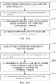
- Figures 1A and 1B are each flow charts of steps used to manufacture a 3D object, in two illustrative embodiments of this invention, respectively.
- the 3D object is printed in accordance with a computer 3D model of the object, created by a CAD program.
- the CAD program may be a free-form NURBS (non-uniform rational basis spline) program, such as Rhinoceros® (available from McNeel North America, Seattle, WA).
- the CAD program may be SolidWorks® (available from Dassault Systèmes SolidWorks Corp., Concord, MA).
- powder is selectively deposited in a physical pattern that corresponds to a "positive image" of a thin slice or section of the 3D object. That is, for each slice of the 3D object: (a) powder is deposited in positions that correspond to positions in the slice where the 3D object exists, and (b) powder is not deposited in positions that correspond to positions in the slice where the 3D object does not exist.
- Thin slices of the 3D CAD model may be created, for example, by starting with a 3D model in STL file format and using the Slice Commander feature of netfabb® Studio software (available from netfabb GmbH, Parsberg, Germany) to create the thin slices.
- the powder may be selectively deposited on substrate layers in many different ways.
- Example 1 (of selective deposit of powder):
- powder may be selectively deposited on a substrate layer by making the powder adhere to a liquid, as follows: A liquid is selectively deposited on a substrate layer, so that some parts of the substrate layer are covered with liquid, and some are not. Then the side of the substrate layer on which the fluid was deposited is flooded with powder (e.g., the powder is poured on this side of the substrate layer). The powder adheres to the liquid. The excess powder (i.e., the powder that is not adhering to the liquid) is removed. For example, this excess powder may be removed by vacuuming. Or, for example, the substrate may simply be flipped over, so that the excess powder falls off. Or the substrate may be turned upside down and flicked with a finger.
- the substrate may be vibrated while the excess powder is removed, in order to facilitate the removal.
- the liquid that is selectively deposited is water (or an aqueous solution that includes a material that slows the evaporation of water).
- the material may be 2-pyrrolidinone.
- it is a different liquid, such as an alcohol.
- the substrate is water sensitive (e.g. if the substrate is polyvinyl alcohol, PVOH), then water may distort or dissolve the substrate. In that case, an alcohol may be used as the liquid that is selectively deposited.
- a surface energy modifier to the substrate, before selectively depositing the liquid.
- Scotchguard® Fabric & Upholstery Protector available from 3M, St. Paul, MN
- other repellents or surface energy modifiers can be used.
- a variety of methods may be used to dispense the liquid.
- a thermal inkjet head or a piezoelectric inkjet head may be used to dispense the liquid.
- the inkjet head may comprise a HP45 cartridge, HP C 6602A cartridge, or HP51604A cartridge (available from Hewlett Packard Corp.) or a Lexmark® 50 cartridge or Lexmark 60 cartridge.
- air pressure may be used to dispense the liquid (e.g., through a 0.005 inch nozzle obtained from the Lee Company, Essex, CT, part INZA650935K). If air pressure is used, the release of air or dispensing of liquid may be controlled by a solenoid valve
- Example 2 (of selective deposit of powder):
- the powder may be selectively deposited by flooding one side of a layer of substrate with powder, then selectively heating the opposite side of the substrate with an appropriate device such as a thermal print head.
- a thermal print head from Mitani Micronics Co., Ltd., Tokyo, Japan may be used.
- the thermal print head includes a high-resolution array of heating elements, which may be selectively turned on or off. In the areas that are heated, the powder melts and adheres to the substrate. The excess powder that has not adhered is removed. Again, this may be done by vacuuming the excess powder, or by simply flipping the substrate layer over. Again, vibration may be used to facilitate the removal of the powder.
- the thickness of the deposited powder can be controlled in this example by doctoring a precise thickness of powder on the substrate.
- Example 3 (of selective deposit of powder):
- powder may be deposited using a selective deposition technique similar to that employed in xerographic printing.
- an electrical charge is imparted to powder particles, which are directed toward the substrate layer, and then selectively adhere to some portions of the substrate but not others, due to electrostatic attraction or repulsion.
- the powder particles adhere to portions of the substrate that have an opposite electrical charge (or that are adjacent to a surface that has such a charge), and are repelled from portions of the substrate that have the same electrical charge (or that are adjacent to a surface that has such a charge).
- Example 4 (of selective deposit of powder):
- the powder may be deposited using a selective deposition technique similar to that employed in magnetographic printing.
- powder selectively adheres to some portions of the substrate layer, but not others, due to magnetostatic interactions between the powder and the substrate layer (or a surface adjacent to the substrate layer).
- the powder may be a single component magnetic toner, or may comprise a colloidal suspension (e.g., a ferrofluid) or may be a dual component toner.
- the step of selectively depositing powder may include a substep of directing solid powder toward the substrate layer in a non-selective manner.
- this substep may comprise flooding the entire layer of substrate with powder.
- this substep may comprise sending electrically charged or magnetized powder toward the entire substrate layer.
- This invention is not limited to the four examples of selective deposition described above, but may be implemented using any technique to selectively deposit the powder.
- liquid is selectively dispensed in a 2D pattern that corresponds to the slice that it is being printed for the particular substrate layer.
- the top of the substrate layer is then flooded with thermoplastic powder.
- the powder adheres to the liquid, but does not adhere to the portions of the substrate layer that are not covered with the liquid.
- the excess powder is then removed. This may be done, for example, by vacuuming the excess powder off, or by the simple expedient of flipping the substrate layer over.
- pressure and heat are applied to the layers of substrate being fused, to melt the powder and to press the layers together.
- the pressure may additionally tend to force the melted thermoplastic to coat the substrate.
- a hot stamp press may be used to apply heat and pressure.
- the substrate may be placed in a heated oven, while pressure is applied with a clamp or other compressive device.
- the pressure may tend to force the molten material to coat the substrate layers.
- a tacking iron may be used to tack the substrate layers together, before inserting them into the oven.
- the powder is caused to melt after it has been selectively deposited: i.e., the melting occurs after the excess powder has been removed.
- the melting is part of the process of selective deposition.
- the print head selectively heats portions of a substrate layer that has been flooded (on the side of the substrate layer opposite from the print head) with powder, so that, in the heated areas, the powder melts and adheres to the substrate. Excess powder is removed. Heat and pressure are then applied, causing the adhered material to melt (or to remain molten) and to coat part of the substrate.
- the molten material then cools and solidifies into a solid that coats a portion of the substrate layer. It also holds multiple substrate layers together.
- the molten material may coat these fibers. When the material solidifies, it continues to coat these fibers.
- How frequently the powder is melted and the pressure is applied may vary. In some implementations, these steps occur once for each layer. In other implementations, at least some of these steps occur less frequently. For example, heat and pressure may be applied only once for every two layers of substrate, or once for every five layers of substrate, etc.
- a portion of the substrate is not coated, because the powder was not present and melted in that area. That excess substrate is removed.
- excess substrate is removed by one or more of: dissolution, polymer degradation, mechanical abrasion, or melting. If dissolution or degradation is employed to remove excess substrate, the dissolution or degradation may be accelerated by agitating and/or heating the agent used for dissolution and/or degradation. For example, any of the following may be agitated or heated to speed the dissolution or degradation: (a) sodium hydroxide or other alkali in aqueous solution or in an alcohol (e.g., ethanol or methanol), (b) potassium hydroxide in an alcohol (e.g., methanol or in ethanol), (c) water, and (d) hydrochloric acid in aqueous solution.
- dissolution or degradation may be accelerated by agitating and/or heating the agent used for dissolution and/or degradation. For example, any of the following may be agitated or heated to speed the dissolution or degradation: (a) sodium hydroxide or other alkali in aqueous solution or in an alcohol (e.g., ethanol or methanol),
- Agitation may be achieved, for example, by ultrasound, a magnetic or paddle stirrer, shaking, or jets of liquid. If mechanical abrasion is used, then it is advantageous to use a substrate material that can be easily removed by abrasion when not coated. The object may be placed in a mechanical tumbler to facilitate abrasion. This invention is not limited, however to the methods of removing excess substrate listed above. Other removal approaches may be employed which rely on a difference in material properties of the substrate and the solidified thermoplastic that causes the former to be more susceptible than the latter to the removal agent.
- the removal of the excess substrate occurs just once, at the end of the process. Alternately, the removal of the excess substrate may occur more than once during the process.
- thermoplastic powder is used.
- the powder may be Shaetti® SF 400 or Shaetti® Fix 1820 thermoplastic powder (available from Shaetti America, Inc., Mooresville, NC) or another powder that melts, flows, and bonds under heat.
- the thermoplastic powder may comprise a polyethylene or other polyolefin.
- polyethylene may have a lower melting point than the substrate, and may be impervious to many solvents, acids and other chemicals that degrade plastics (and thus would not be affected if such chemicals were used to remove excess substrate).
- thermosettable powder that melts and flows sufficiently to coat the substrate may be used.
- Substrates and Removal Agents Substrate Material used for removal of excess substrate (e.g., by dissolution or degradation)
- PET Polyethylene terephthalate
- Alkali e.g., Everclear® grain alcohol and sodium hydroxide
- the alcohol may comprise ethanol or methanol
- potassium hydroxide e.g., sodium bicarbonate
- PVA polylactic acid
- PVA sodium hydroxide
- methanol in aqueous solution
- PVOH polyvinyl alcohol
- Nylon polyamide
- silk hydrochloric acid fiberglass hydrofluoric acid acetone, methanol, methylene chloride, toluene, and xylene.
- PLA available from Ahlstrom Chirnsdale Ltd., Chirnsdale, Scotland, U.K., and from C.L. Enterprises, Wenzhou, China
- PLA available from Ahlstrom Chirnsdale Ltd., Chirnsdale, Scotland, U.K., and from C.L. Enterprises, Wenzhou, China
- the substrate comprises a woven material.
- the substrate may comprise a non-woven textile.
- non-woven PVOH available from Freudenberg USA
- the non-woven substrate may comprise HV 7841, HV 7801 or HV CTR2863A polyester, each available from Hollingsworth and Vose (East Walpole, MA), or may comprise A0514WHT polyester, available from Freundenberg.
- the substrate may comprise paper or another cellulose-based or plant fiber-based material.
- water-soluble paper may be used for the substrate.
- the water soluble paper may be of the type described in US patent 3,431,166 (in which paper is reacted with alkali during manufacture).
- the paper may employ polyvinyl alcohol (PVOH) which is used to bind paper fibers together.
- PVOH polyvinyl alcohol
- the former type of water soluble paper may be obtained from Aquasol Corporation (North Tonawanda, NY); and the latter type may be obtained from Hollingsworth and Vose Company (East Walpole, MA).
- a problem with water-soluble paper is that it tends to swell when exposed to water. This swelling may be reduced by using a high pressure water jet, which tends to rapidly remove the paper that has been exposed to water, before the water can migrate into paper that has been partially coated with melted powder.
- This invention is not limited to the substrate materials and solvents or degrading agents listed in the table above, but may also be implemented with other substrate materials, and solvents and degrading agents.
- different substances may be applied to or incorporated in the substrate layers to modify the absorption characteristics or surface energy of the substrate.
- the substrate's absorption characteristics may be modified in this way with respect to a variety of liquids, such as melted powder, or liquid solvent or degrading agent, or a liquid that is dispensed for the powder to adhere to.
- a sizing material that acts as a filter or a glaze may be used for this purpose.
- Scotchguard® Fabric & Upholstery Protector available from 3M, St. Paul, MN
- repellents mentioned above, is an example of applying a substance that changes the absorption characteristics and surface energy of the substrate layer.
- a registration mechanism is employed to cause the layers of substrate to be aligned during the 3D printing process.
- guide posts in a registration form may be inserted into guide holes in the substrate layers.
- a corner of each substrate layer may be pushed into a guide corner, to align the layer with other layers.
- a light sensor or camera may be employed to determine whether substrate layers are aligned.
- This invention is not limited to the registration techniques described above, but may employ any type of registration to align the substrate layers.
- Figure 2A shows a substrate layer 201, in an illustrative implementation of this invention.
- Figure 2B is a magnified view of part of the same substrate layer 201, showing woven threads (e.g., thread 203) in the substrate layer.
- Figure 2C is a magnified view of part of thread 203, showing fibers (e.g., 205) in thread 203.
- the substrate is woven and fibrous.
- non-woven, fibrous substrates may be used instead.
- the substrate may comprise a composite, nonwoven material that includes threads, short fibers, long fibers, or whiskers.
- the substrate may comprise spherical particles, ellipsoidal particles, flakes, small platelets or small ribbons (or particulates of any other shape) which are joined together by a glue or other binding material.
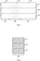
- Figure 3 is a cross-sectional view of three substrate layers 301, 302, 303, after thermoplastic powder has melted, coated a portion of the substrate layers, cooled and solidified, in an illustrative embodiment of this invention.
- a portion 305 of these substrate layers is coated by the solidified thermoplastic.
- Another portion 307 of these substrate layers is not coated by the solidified thermoplastic. The details of the coating may vary, depending on the implementation.
- the solidified thermoplastic may coat, infiltrate, penetrate or encapsulate a portion of the substrate layer, or substructures in a portion of the substrate layer (such as threads, short fibers, long fibers, whiskers, spherical particles, ellipsoidal particles, flakes, small platelets, small ribbons, particulates of any other shape).
- the thickness of the coating may vary, depending on the implementation.
- the way in which the solidified thermoplastic connects or bridges between substrate layers may vary, depending on the implementation.
- Figure 4 is a cross-sectional view of the same three substrate layers, after excess substrate (307 in Figure 3 ) has been removed. That is, it shows these three substrate layers, after removal of the portion of the substrate that is not coated by the solidified thermoplastic.
- Figure 5 shows apparatus used to selectively deposit liquid (to which powder adheres), in an illustrative implementation of this invention.
- Registration guide posts 501 are inserted through a substrate layer 503 in order to properly align the substrate layer 503.
- a solenoid valve 505 is used to selectively dispense liquid from a liquid reservoir 507 though a nozzle 509 unto the substrate layer 503.
- the nozzle 509 is rastered in a 2D plane 510 that is parallel to, and above, the substrate layer 503, so that the liquid is selectively deposited at desired x, y coordinates of the substrate layer 503, and not deposited in other areas of the substrate layer 503.
- a stepper motor 511 actuates two belts (not shown) that causes a support member (not shown) to move along two rails (not shown) in a direction parallel to the x axis.
- a second stepper motor (not shown) and third belt (not shown) are mounted on the support member, and are used to move a nozzle support (not shown) in a direction parallel to the y axis.
- the nozzle 509 is attached to the nozzle support. Together, the two stepper motors can move the nozzle 509 to any desired x, y coordinate above the substrate layer.
- a microprocessor 513 controls the stepper motors and the solenoid valve, thereby controlling when and where liquid is dispensed on the substrate layer 503.
- the stepper motors may cause the nozzle 205 to move in other 2D patterns in the 2D plane to cause the liquid to be deposited at certain x, y coordinates.
- Figure 5 does not show apparatus for heating and pressing multiple layers of substrate, or for removing excess substrate.
- the substrate layer is moved to a different position before those steps occur.
- computer processors are used to control the 3D printing process.
- FIG. 6 is a block diagram that shows a plurality of processors, in an illustrative implementation of this invention.
- a CAD model of a desired 3D object in STL file format is created using a remote processor 601.
- This processor 601 employs software (such as netfabb® Studio software) to create a machine-specific build file.
- the machine-specific build file is exported to a second processor 603.
- this second processor controls the operation, including movements, of: (1) an inkjet head or other device that selectively deposits liquid, (2) actuators that spread out the powder on the substrate and then remove the excess powder, (3) a thermal print head, (4) a hot stamp press, or (5) actuators that feed or flip over substrate layers.
- this invention may be implemented with other arrangements of processors.
- more than one remote processor and more than one onboard processor may be employed, and any of the above tasks may be handled by one or more of these different processors.
- an ink jet printer is used to selectively deposit liquid on a substrate layer.
- the liquid is conventional ink used for an inkjet printer. Alternately, water or another wetting liquid may be used as the liquid.
- the ink jet head is rastered (or otherwise moved in a 2D pattern) across the substrate layer, using x and y stepper motors. As inkjet printer head is rastered, it can print multiple lines of ink with each pass.
- the layer is flooded with powder (e.g., thermoplastic powder). The powder adheres where the liquid is present. Then excess powder (that does not adhere to the liquid) is removed.
- a heated press is used to melt the powder and to press layers of substrate together. All of these steps - inkjet printing, application of powder and removal of excess powder, and the heated press or iron - may be automated, to improve the precision and speed of steps in the process.
- This approach (with an ink jet printer and heated press) has a number of advantages. First, it may be implemented using simple, low-cost apparatus. Second, it is fast: for example, ink jet printers can achieve rates of 30 sheets per minute. Third, objects can be printed in color and decorated. For example, in a prototype of this invention, dyes or pigment-based inks can be used, allowing fully decorated parts to be made.
- the ink jet heads can be inexpensive. For example, disposable, inexpensive thermal inkjet heads (such as HP45 available from Hewlett Packard Company) can be used.
- thermoplastic may be selectively applied to large (long) sheets of substrate.
- thermoplastic may be selectively applied to large (long) sheets of substrate.
- the surface tension and evaporation of the liquid can be modified by using a liquid other than water, or by adding other compounds (such as ethylene, propylene glycol or 2-pyrrolidinone) to the water.
- the substrate is comprised of polyamide (nylon) fabric.
- a first layer of substrate is placed on a hot stamp press.
- a second layer of substrate is placed on another surface (not on the hot stamp press). Water is then selectively applied to that second substrate layer.
- the second layer is then flooded with Shaetti® SF 400 thermoplastic powder. The powder adheres to the water that was applied to the second layer.
- the second layer is turned upside down, which causes the excess powder (which is not adhering to the water) to fall off.
- the second layer of substrate is then placed in the hot stamp press, while still upside down, with the powder adhering to the bottom of the second layer. When it is so positioned, the second layer is on top of the first layer.
- the hot stamp press then heats and presses the two layers together.
- the process is repeated by adding a third layer of substrate, fourth layer and so on, each in the same manner as the second layer.
- the hot stamp press does a "stamp" it melts the powder beneath the top substrate layer.
- the resulting molten material coats a portion of the substrate layers, then cools and solidifies, causing the then current top and second-to-top layers of substrate to adhere to each other.
- the portion of the substrate to which the powder adhered is coated in a solidified plastic material.
- the resulting object is taken off the hot stamp press. It is then placed in an aqueous solution of hydrochloric acid.
- the hydrochloric acid causes the excess substrate (which is not coated by the solidified material) to dissolve.
- the solution is heated and stirred by, for example, a magnetic stirrer.
- This 3D object comprises solidified plastic (that resulted when the thermoplastic powder cooled) and the portion of the nylon substrate that it coats.
- each layer of substrate has guide holes in it.
- Registration guides that are, for example, posts attached to the hot stamp press.
- Scotchguard® Fabric & Upholstery Protector (available from 3M, St. Paul, MN) may be sprayed onto each substrate layer before liquid is selectively deposited on the layer. This reduces the amount of liquid that is absorbed by the substrate and the distance the liquid spreads in the substrate. Alternately, or in addition, each substrate layer may be suspended over a frame, so that the center portion of the layer is not touching any solid surface. This, too, tends to reduce the absorption of liquid by the substrate, and the spreading of the liquid.
- an alcohol instead of water may be selectively applied to the substrate layers.
- the substrate layers may be aligned and placed, one on top of another, in a compressive device that is tightened to apply pressure to compress the substrate layers together.
- This device once tightened, may be placed in an oven (e.g., a conventional toaster oven).
- the excess substrate (comprised of polyamide) is removed with hydrochloric acid.
- water soluble paper is selectively printed with water using a 0.005 inch minstac nozzle obtained from the Lee Company, Essex, CT (part INZA650935K).
- the nozzle is rastered in a line-by-line pattern (or otherwise moved in a 2D pattern) above the substrate layer using two stepper motors that move in x and y directions.
- a microcontroller controls the stepper motors. It also controls the opening and closing of the valve in the nozzle. When the valve is open, water under pressure is deposited on the substrate layer.
- the paper that is used has been cut on a laser cutter, with two registration holes in the top of the paper.
- Paper is inserted into a machine where it is aligned on a registration form, and a "slice" of the object is printed with water on the paper.
- the water is selectively printed in a pattern that corresponds to the particular slice.
- the paper is then flooded with Shaetti® SF 400 thermoplastic powder which adheres only where the water has been deposited.
- the paper is then turned upside down and the excess powder falls off from the areas where no water has been deposited.
- the piece of paper for the first layer is then set on a registration form with two registration rods, on top of a bottom sheet of paper that was previously placed in the registration form.
- the paper with the powder attached is placed powder side down.
- This paper is then tacked to the bottom sheet using a tacking iron. This process is repeated multiple times until each layer of the object has been printed.
- the tacking iron is used to insure that powder remains attached to the paper after the
- the sandwich of paper is clamped with a C-clamp using a rubber stopper between the C-clamp and the paper sandwich so that the force is retained as the paper sandwich is compressed when it is heated.
- This assembly is then put in an oven above the melting temperature of the thermoplastic powder and for a period of time which is longer as the part becomes larger. This causes the thermoplastic powder to penetrate the paper and glue the sheets of paper together.
- the paper stack is then removed from the oven and allowed to cool for about half an hour, allowing the thermoplastic to cool and solidify. Then the stack of paper is placed in a stream of water from a faucet. The water may be hot, since elevated temperature helps in dissolution.
- a jet of water may also be used to accelerate the removal of the excess paper (i.e., the paper that is not coated with plastic).
- the excess paper is removed, resulting in a 3D object.
- Objects that are produced using this prototype are stiff and have good mechanical integrity. Before the excess substrate is removed, it acts as support for the 3D object being produced, allowing for a wide range of geometries to be constructed.
- a heated press such as a hot stamping press
- a heated press it can be easy to control the temperature, pressure and duration of each heat/pressure step.
- the paper layers may be aligned and placed, one on top of another, in a compressive device that is tightened to apply pressure to compress the substrate layers together.
- the compressive device once tightened, may be placed in an oven (e.g., a conventional toaster oven).
- the compressive device may include springs or other elastic components that continue to apply pressure even if the thickness of the paper layers decreases (e.g., due to compression).
- an inkjet printer is used.
- the inkjet printer selectively deposits liquid on a substrate layer (so that the liquid is on some parts of the substrate layer and not on other parts of the substrate layer).
- the inkjet printer prints a pattern of liquid on the substrate layer.
- the substrate layer is then flooded with thermoplastic powder.
- the powder adheres to the substrate in accordance with the printed pattern (i.e., the powder adheres to the portion of the substrate layer where the liquid has been deposited, but does not adhere to the rest of the substrate layer).
- thermoplastic powder is selectively deposited on the substrate layer in a pattern, where the pattern corresponds to the pattern of liquid printed by an inkjet printer.
- a rectangular layer of substrate is taped to an 8.5 inch by 11 inch sheet of conventional paper. When doing so, the outer edges of the substrate layer are aligned with a rectangle printed on the sheet of paper
- an HP 820CSE inkjet printer (manufactured by Hewlett Packard Company, Palo Alto, CA) prints a pattern of ink on the substrate layer. Conventional ink for that printer is used.
- the printed pattern comprises a grid that defines a matrix of tiles. In this printed pattern, a different cross-sectional "slice" of a three-dimensional object is printed in each of the tiles, respectively.
- the substrate may comprise PVOH.
- water may be used to dissolve the excess substrate.
- the substrate may comprise PLA.
- excess substrate may be removed by placing the rectangular cuboid in a solution of methanol and KOH. In order to speed the removal, this solution may be agitated with a magnetic stirrer, or may be placed in an ultrasonic tank.
- Figure 7 shows a pattern that has been inkjet-printed on a substrate layer 701.
- the pattern comprises a grid that defines a 4 x 3 matrix of tiles.
- a different cross-sectional "slice” e.g., 704 of a ring torus has been printed by the inkjet printer.
- the upper left tile 705 in Figure 7 is a null slice of the ring torus, i.e., it does not include a part of the ring torus).
- Figure 7 shows how the substrate layer is aligned with a sheet of paper 707.
- the substrate layer is taped on the paper so that the outer edges of the substrate layer align with one of these pre-printed rectangles on the sheet of paper. More specifically, in Figure 7 , three rectangles, nestled inside each other, have been pre-printed on the paper. The outer rectangle 711 and central rectangle 709 of these three rectangles are visible in Figure 7 . The innermost of these three pre-printed rectangles on the sheet of paper is not visible in Figure 7 . However, innermost rectangle is aligned with, and lies directly beneath, the outer edge 713 of the rectangular grid (visible in Figure 7 ) that was printed on the substrate layer by the inkjet printer.
- thermoplastic powder e.g. Schaetti® Fix 400 powder
- the excess powder is then removed, by turning the paper upside down and tapping the paper with a finger. Other removal methods may be used, such as vacuuming or blowing the excess powder away.
- the substrate layer is then aligned on a laser cutter.
- the laser cutter then cuts lines that separate the substrate layer into the tiles and cuts two registration holes in each of the tiles.
- each substrate layer is divided into 12 tiles, with a different "slice" of a ring torus printed on each tile, respectively.
- These tiles are placed in a device for applying pressure (a "compressive device"), one tile on top of another.
- the compressive device includes one or more elastic components (e.g., springs) to maintain pressure on the substrate layers even if they compress.
- the tiles are aligned by inserting two guide holes in each tile, respectively, through two guide posts in the press.
- Figure 8 shows a compressive device 803, after a number of substrate tiles (layers) (e.g., 801) have been placed in it, one on top of the other.
- substrate tiles layers
- substrate tiles for all of the "slices" of the ring torus are placed into the compressive device.
- the total number of substrate tiles is more than 12.
- the process of printing 12 slices on 12 tiles on a substrate layer is repeated, layer by layer, until tiles for all of the slices have been printed).
- Each of the tiles is itself a substrate layer, and is cut from a larger layer of sheet of substrate.
- the substrate layers (tiles) that have been inserted into the compressive device are then compressed together by that device.
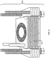
- Figure 9 shows substrate layers being compressed in the compressive device 903. Screws 905, 907, 909, 911, plates 913, 915 and a spring 917 in the compressive device are used to exert pressure.
- the compressive device (with the substrate layers in it) is then placed in a conventional toaster oven.
- the compressive device includes both a spring (to maintain pressure on the substrate layers even if they compress) and (2) a stand-off, clutch, brake or damper to limit movement of the compressive device.
- the springs in the compressive device may be omitted and simple mechanical pressure of the screws can be used.
- a hot stamping press can be used to apply pressure.
- thermoplastic powder to melt.
- the molten material coats the substrate layers.
- the compressive device (with the substrate layers in it) is then removed from the oven, and the substrate layers are allowed to cool.
- the molten material then solidifies. As it does so, it binds (fuses) substrate layers together.
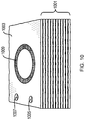
- Figure 10 shows the substrate layers 1001, after they have been fused together (as described in the preceding paragraph) into a rectangular cuboid 1003.
- a 3D toroid is being fabricated, and the upper-most slice 1009 of the toroid is visible at the top surface of the cuboid 1003.
- Two registration holes 1007 and 1009 are visible in excess substrate that will be subsequently removed.
- Excess substrate (that has not been covered by the solidified material) is then removed.
- a ring torus 1100 remains after excess substrate in a rectangular cuboid has been removed.
- This invention is not limited to melting of the powder, in which solid powder becomes liquid.
- Other transitions may be employed.
- the powder may undergo a glass transition that allows it to penetrate the substrate.
- the powder may be transformed into in a bi-phasic material that can penetrate the substrate.
- the substrate may be a composite that comprises particles, ellipsoidal particles, flakes, small platelets, small ribbons, or particulates of any other shape (or a combination of two or more of these) which are bound or glued together by another material.
- a powder grain 1201 comprises a solid outer layer 1205 of thermoplastic or thermoset plastic.
- the outer layer 1205 encapsulates liquid 1203.
- the powder may be selectively deposited. Pressure (and heat) may be applied burst the encapsulation.
- the resin or liquid may then infiltrate into the substrate layers.
- the resin may harden upon exposure to (1) air, (2) a reactant, reagent, catalyst or solvent, or (3) electromagnetic radiation.
- grains of powder encapsulate (or microencapsulate) epoxy resin are also mixed into the powder.
- the powder mixture is selectively deposited. Pressure (and heat) may be applied burst the encapsulation, so that the resin penetrates into the substrate layers and then hardens.
- the powder mixture comprises two types of grains: first, completely solid grains of epoxy hardener 1207; and second, grains that comprise a solid outer layer 1205 that encapsulates a liquid epoxy resin 1203.
- the substrate may be flooded with powder that encapsulates liquid.
- Pressure may be selectively applied (e.g., with a dot matrix print head) to burst the encapsulation, so that the liquid infiltrates the substrate layers and then hardens.
- the means may comprise a heating element.
- the heating element may comprise any artificial heat source that heats by one or more of conduction, convection or radiation.
- the heating element may comprise: (1) a resistor or any other resistive heating element; (2) any other device that converts electricity into heat by ohmic heating; (3) a hot stamp press or any other apparatus for applying heat and pressure; (4) an oven; or (5) an artificial source of electromagnetic radiation, including a heat lamp, an artificial infrared light source, a laser; or an artificial source of microwave radiation.
- the means may comprise an artificial pressure source, including a press, clamp, iron, roller, pump, piston, or elastic element (e.g. spring) for applying pressure.
- the pressure may be used, for example, to compress layers together or to squeeze the flowing substance into interstices in the substrate layers. Or, for example, the pressure may be used to crush, rupture or burst grains of powder that encapsulate liquid. The liquid may then flow, and may harden or cause something else to harden.
- the heating element or pressure source may be configured to transform powder into a substance that flows and then subsequently hardens.
- the means may comprise a reagent, reactant, catalyst, solvent or solute used in a chemical reaction. The reaction may soften or harden all or a portion of the powder.
- An applicator may be configured to apply, deposit or deliver the reagent, reactant, catalyst, solvent or solute to the powder.
- the means may comprise an artificial source of electromagnetic radiation.
- the radiation may, for example, be used for hardening the powder, including by curing.
- the radiation source may be configured to transform powder into a substance that flows and then subsequently hardens
- Figure 13 is a high-level block diagram of some hardware that may be used in this invention.
- One or more processors 1301 control an applicator 1303, a heating element 1305, an actuator 1307, an artificial pressure source 1309, and a stirrer in a container of liquid 1311.
- the applicator 1303 deposits powder in positive regions, but not in negative regions, of substrate layers.
- the heating element 1305 transforms the powder into matter that flows and then hardens.
- the resulting hardened material is disposed in a spatial pattern that infiltrates the substrate layers.
- the artificial pressure source 1309 may comprise a press, clamp, spring, elastic element, or other device for compressing the substrate layers.
- the stirrer may be used to stir a liquid that is used for removing excess substrate.
- Figures 14A and 14B are each flow charts of steps used to fabricate a 3D object, in two different illustrative embodiments of this invention, respectively.
- the melted or softened powder may enter the substrate layers by absorption.
- this invention may comprise an article of manufacture.
- using powder permits the finished 3D product to have a high resolution in at least one dimension.
- powder is selectively deposited on substrate layers. For each layer, two substeps occur: first, an inkjet head is used to dispense liquid, and second, powder is applied and adheres to the liquid. The powder is then heated and flows, infiltrating the layers, and cooling into a solidified material that binds the substrate layers together.
- the spatial resolution of an exterior surface of the 3D product may be approximately equal to the resolution of the inkjet head in an x, y direction and to the thickness of a substrate layer in the z direction.
- an article of manufacture may comprise substrate layers infiltrated by a hardened material.
- the hardened material may be a thermoplastic.
- an exterior surface of the hardened thermoplastic may have a spatial resolution of 60 or more dots per centimeter in at least one dimension, and the thermoplastic may have a viscosity of 50 or more centipoise at 50 degrees centigrade above the thermoplastic's melting temperature.
- an exterior surface of the hardened thermoplastic may have a spatial resolution of 170 or less microns in at least one dimension, and the thermoplastic may have a melt flow rate of at least 70 grams/10 minutes.
- This invention may be implemented in many different ways. Here are some examples:
- Embodiments of the invention provide a method of fabricating a 3D object, which 3D object comprises a plurality of substrate layers that are infiltrated by and bound together by a hardened material, the method comprising the following steps, in combination: (a) positioning powder on all or part of at least one of the layers; (b) repeating step (a) for remaining layers in the plurality of substrate layers; and (c) transforming at least some of the powder into a substance that flows and subsequently hardens into the hardened material, which hardened material is disposed in a spatial pattern that infiltrates at least one positive region in a set of the substrate layers and does not infiltrate at least one negative region in the set; wherein the powder is transformed in step (c) after being positioned in either step (a) or step (b), and wherein the substrate layers have at least one material property that is different than any material property of the hardened material.
- the positioning may comprise selectively applying the powder to part but not all of a surface of the layer; (2) the positioning may be in accordance with a machine-readable digital model of a slice of the 3D object; (3) the transforming may comprise melting at least part of the powder; (4) the powder may comprise grains that each, respectively encapsulate a liquid, and the transforming may comprise rupturing, bursting or crushing at least some of the grains; and (5) the transforming may comprise a chemical reaction.
- Embodiments of the invention provide a method of fabricating a 3D object, which 3D object comprises a plurality of layers and a hardened substance that binds the layers together, the method comprising the following steps, in combination: (a) selectively depositing powder on a positive region, but not on at least part of a negative region, of one of the layers; (b) repeating step (a) for remaining layers in the plurality of layers; (c) transforming at least some of the powder into matter that flows and subsequently becomes the hardened substance, which hardened substance is disposed in a spatial pattern that infiltrates the layers; and (d) removing material from at least one negative region of at least one substrate layer; wherein the powder is transformed in step (c) after being deposited in either step (a) or step (b), and wherein the substrate layers have at least one material property that is different than any material property of the hardened substance.
- the selectively depositing powder on a positive region of the one of the layers may comprise a first substep and a second substep, the first substep comprising selectively depositing liquid on the positive region, and the second substep comprising positioning the powder on or adjacent to the one of the layers to adhere the powder to the liquid;
- the selectively depositing may further comprise a third substep, which third substep comprises removing powder that does not adhere to the liquid;
- the layers may comprise PET or PLA and an alkali, alone or together with one or more other substances, may be used for the removing
- Embodiments of the invention provide an apparatus for fabricating a 3D object, which object comprises a plurality of layers and a hardened substance, the apparatus comprising, in combination: (a) an applicator, the applicator being configured for selectively depositing powder in at least some positive regions, but not in at least some negative regions, of at least some of the layers; and (b) a heating element, the heating element being configured for transforming the powder into matter that flows and then hardens into the hardened substance, which hardened substance binds the layers together and is disposed in a spatial pattern that infiltrates the layers; wherein the substrate layers have at least one material property that is different than any material property of the hardened substance.
- the apparatus may further comprise an artificial pressure source, the pressure source being configured for applying pressure to one or more of the layers; (2) the pressure may be applied during softening of the powder; (3) the apparatus may further comprise one or more actuators, the one or more actuators being configured for translating one or more of the powder and the layers; (4) the apparatus may further comprise an additional actuator, the additional actuator being configured for translating the applicator into different positions while the applicator selectively deposits the powder; (5) the apparatus may further comprise a processor, the processor being configured for outputting control signals to control the applicator and heating element; (6) the processor may be adapted to output control signals to control the selectively depositing of powder for each of the at least some substrate layers, respectively, in accordance with digital data that specifies different slices, respectively, of the 3D object; and (7) the apparatus may further comprise a container, the container being configured for containing a liquid, which liquid includes a solvent or degrading material that is used for removing material from the at least some negative regions.
- Embodiments of the invention may provide apparatus for fabricating a 3D object, which object comprises a stack of substrate layers that have been infiltrated by a hardened material, the apparatus comprising, in combination: (a) an applicator, the applicator being configured for positioning powder on the layers; and (b) means for transforming the powder into a substance that flows and then hardens into the hardened material, which hardened material binds the layers together and is disposed in a spatial pattern that infiltrates at least one positive region in a set of the layers and does not infiltrate at least one negative region in the set; wherein the substrate layers have at least one material property that is different than any material property of the hardened substance.
- Embodiments of the invention may provide an article of manufacture comprising a plurality of layers that are infiltrated by and bound together by a hardened material, wherein the hardened material comprises either a thermoplastic or thermosettable plastic and exhibits a set of one or more characteristics, which set is sufficient for distinguishing the hardened material as having formed as a result of powder positioned on the layers, respectively, at least partially softening and then hardening.
- the hardened material comprises either a thermoplastic or thermosettable plastic and exhibits a set of one or more characteristics, which set is sufficient for distinguishing the hardened material as having formed as a result of powder positioned on the layers, respectively, at least partially softening and then hardening.
- the set of characteristics may comprise a pattern resulting from at least some grains of powder not completely softening; (2) the set of characteristics may comprise a pattern resulting from a first grain of powder flowing, after at least partially softening, more viscously than another grain of powder flows, after at least partially melting, or from part of the first grain flowing more viscously, after at least partially softening, than another part of the first grain flows, after partially softening; (3) the set of characteristics may comprise a crystalline or amorphous structure resulting from incomplete or nonhomogeneous melting of grains of powder; (4) the substrate layers may be woven; (5) the substrate layers may be woven and fibrous; (7) the substrate layers may be non-woven; and (8) the article may include more than one hardened material, each of which has a different shade or color.
- Embodiments of the invention may be implemented as an article of manufacture comprising a stack of substrate layers that are infiltrated by a hardened material, wherein an exterior surface of the hardened material has a spatial resolution of 60 or more dots per centimeter in at least one dimension, and wherein the hardened material comprises a thermoplastic, which thermoplastic has an viscosity of 50 or more centipoise at 50 degrees centigrade above the thermoplastic's melting temperature.
- Embodiments of the invention may provide an article of manufacture comprising a plurality of substrate layers that are infiltrated by and bound together by a hardened material, wherein an exterior surface of the hardened material has a spatial resolution of 170 or less microns in at least one dimension, and wherein the hardened material comprises a thermoplastic, which thermoplastic has a melt flow rate of at least 70 grams/10 minutes.
- Embodiments of the invention may provide a process for fabricating a 3D object, which process comprises, in combination: (a) depositing thermosettable or thermoplastic powder on a second layer of substrate, in a pattern, for each substrate layer, respectively, defined by a digital description of a slice or section of a 3D object, (b) positioning the second layer of the substrate adjacent to a first layer of substrate so that edges of the first and second substrate layers are aligned and so that powder that was deposited on the second layer is between the first and second layers, (c) repeating step a with respect to a third layer of substrate, (d) positioning the third layer substrate adjacent to the second layer so that edges of the second and third layers are aligned and so that powder that was deposited on the third layer is between the second and third layers, (e) repeating steps (c) and (d), layer by layer, until powder has been selectively deposited on substrate layers corresponding to all of the layers of the 3D object, (f) applying sufficient heat and pressure to at least two of these substrate layers to (1)
- Embodiments may also provide a product produced by the process described in the immediately preceding paragraph.
- Embodiments of the invention may provide an article of manufacture, comprising at least twenty layers of substrate, each layer being bound to at least one adjacent layer by (and at least partially coated by) a material that comprises a thermoplastic or thermosettable polymer.
- the substrate layer may be woven, (2) the substrate layer may be woven and fibrous, (3) the substrate layer may be non-woven, (4) the substrate layer may be non-fibrous, (5) at least a portion of the external, macroscopic geometry of the substrate may be polyhedral in shape, (6) the macroscopic exterior of the article of manufacture may include multiple rectilinear faces in different planes, (7) the macroscopic exterior of the article of manufacture may define multiple compound or complex curves, (8) substrate layers of such article may be coated at least in part with a repellant or sizing, (9) different portions of the polymer may have different colors, and (10) the polymer may cover fibers in substrate layers.
- Each layer can be planar or flat.
- Embodiments of the invention may provide apparatus comprising, in combination: (a) at least one applicator for depositing thermoplastic or thermosettable powder on multiple layers of substrate, in a pattern, for each substrate layer, respectively, defined by a digital description of a slice or section of a 3D object, (b) at least one heat source for applying heat to the substrate layers, (c) at least one pressure source for applying pressure to the substrate layers, and (d) one or more computer processors for (I) accepting and processing digital data describing a section or slice of a 3d object, and (II) outputting control signals for controlling the operation of the applicators.
- the apparatus may further comprise one or more of the following: (1) a container for containing a liquid, which liquid includes a solvent or degrading material that is used for removing excess substrate, the excess substrate being that portion of the substrate that is not coated by thermoplastic or thermoset material after it melts or softens and then cools, (2) a heat source for heating the liquid solvent or degrading material, and (3) one or more actuators for translating one or more of the powder, substrate sheets and the finished or partially finished 3D object.
- a container for containing a liquid which liquid includes a solvent or degrading material that is used for removing excess substrate, the excess substrate being that portion of the substrate that is not coated by thermoplastic or thermoset material after it melts or softens and then cools
- a heat source for heating the liquid solvent or degrading material
- one or more actuators for translating one or more of the powder, substrate sheets and the finished or partially finished 3D object.
- the one or more computer processors may do one or more of the following: (1) accept and process data from one or more sensors, such as heat or pressure sensors, or sensors for determining whether and to what extent adjacent substrate layers are aligned, (2) control the at least one heat source, (3) control the at least one pressure source, (4) control the one or more actuators, and (5) accept data indicative of input from a human user.
- sensors such as heat or pressure sensors, or sensors for determining whether and to what extent adjacent substrate layers are aligned
- Embodiments of the invention also provide a 3D object fabricated using any of the fabrication techniques described above.
- a 3D object may be comprised of composite materials. These composite materials may comprise substrate layers coated by solidified thermoplastic or thermoset polymer.
- an “applicator” means a device for applying a substance to a surface, or otherwise depositing, dispensing or moving the substance.
- the substance may be a powder or a liquid.
- an applicator may comprise an inkjet head.
- coat means to (at least partially) coat, infiltrate, penetrate or encapsulate. Grammatical variations of "coat” shall be construed accordingly.
- To coat a substrate means to coat the substrate or substructures of the substrate (such as threads, short fibers, long fibers, whiskers, spherical particles, ellipsoidal particles, flakes, small platelets, small ribbons, particulates of any other shape).
- a “heating element” means an artificial heat source that heats by one or more of conduction, convection, radiation or induction.
- a “heating element” includes, among other things: (1) a resistor or any other resistive heating element; (2) any other device that converts electricity into heat by ohmic heating; (3) a hot stamp press or any other apparatus for applying heat and pressure; (4) an oven; (5) an inductive heater; and (6) an artificial source of electromagnetic radiation, including a heat lamp, an artificial infrared light source, a laser, or an artificial source of microwave radiation.
- a layer includes (a) to infiltrate or penetrate into the interior of the layer and to at least partially cover at least some interior substructures of the layer (or of the region); (b) to be absorbed into the layer, or (c) to be arranged in a pattern that results from infiltrating as described in (a) or (b).
- a spatial pattern "infiltrates” a layer if the pattern results from infiltrating as described in (a) or (b).
- a hardened material "infiltrates” a layer if the hardened material is arranged in a pattern that results from infiltrating as described in (a) or (b).
- a region of a layer shall be construed in like manner as to infiltrate a layer. Unless the context requires otherwise, if a substance x "infiltrates" substance y, this implies that x has at least one material property that is different than any material property of y.
- melt includes (1) to melt or soften by the application of heat and (2) to dissolve.
- a "negative" region of a substrate layer, which layer is used in fabricating a 3D object means a region that is not (or will not be) included in the 3D object when fabrication of the 3D object is complete.
- a "positive" region of a substrate layer, which layer is used in fabricating a 3D object means a region that is (or will be) included in the 3D object when fabrication of the 3D object is complete.
- binder includes (1) a material comprising entirely solid grains, (2) a material comprising at least some grains that each, respectively, encapsulate a liquid, (3) any granular material, and (4) a material comprising solid particles that may flow, relative to each other, when accelerated.
- a “set” consists of one or more elements.
- the term “set” does not include an empty set with no elements.
- soften includes (1) to soften below a melting temperature and above a glass transition temperature, (2) to melt above a melting temperature, (3) to transition from a higher to a lower elastic modulus, (4) to transition from a higher to a lower viscosity, or (5) to otherwise soften.
- the adjective “soft” shall also be construed in like manner. For example, the adjectives “soft” and “softened” each include “melted”.
- a list of multiple steps in a process does not imply, except to the extent that the context requires otherwise, that: (1) the steps occur in any particular order or sequence, including the order or sequence listed; (2) the steps occur only once; (3) the different steps occur the same number of times during the process, or (4) a particular step is applied to the same thing each time that the particular step occurs (for example, except to the extent that the context requires otherwise, a specific step that is described as applying to "a layer” may apply to a different layer each time that this specific step occurs).
- list includes "description” or "describe”.
- 3D means three-dimensional.
- Grammatical variations of defined terms shall be construed in like manner as the defined terms. For example, if a verb is defined in one conjugation, then other conjugations of that verb shall be construed in like manner. Or, for example, if a noun is defined in one declension, then other declensions of that noun shall be construed in like manner. Or for example, the noun “infiltration” shall be construed in like manner as the defined verb "infiltrate”. Or, for example, the adjective “softened” shall be construed in like manner as the defined verb "soften”.
Claims (16)
- Procédé de fabrication d'un objet 3D, lequel objet 3D comprend une pluralité de couches de substrat (301, 302, 303) qui sont liées ensemble par un matériau durci qui s'infiltre dans celles-ci, le procédé comprenant les étapes suivantes, en combinaison, consistant :(1a) à positionner sélectivement une poudre sur une partie d'au moins l'une de la pluralité de couches de substrat, la partie correspondant à une partie de l'objet 3D ;(1b) à répéter l'étape (1a) pour les couches restantes de la pluralité de couches de substrat ; et(1c) à transformer au moins une partie de la poudre en une substance qui s'écoule et durcit ensuite en le matériau durci, lequel matériau durci est disposé dans un motif spatial qui s'infiltre dans au moins une région positive de la pluralité de couches de substrat et qui ne s'infiltre pas dans au moins une région négative de celles-ci ;dans lequel la poudre est transformée dans l'étape (1c) après avoir été positionnée dans les étapes (1a) et (1b), et dans lequel les couches de substrat ont au moins une propriété matérielle qui est différente de quelconque propriété matérielle du matériau durci.
- Procédé de la revendication 1, dans lequel le positionnement sélectif (1a) est conforme à un modèle numérique lisible par machine d'une tranche de l'objet 3D.
- Procédé de la revendication 1 ou 2, dans lequel la transformation (1c) comprend la fusion d'au moins une partie de la poudre.
- Appareil de fabrication d'un objet 3D, lequel objet comprend une pluralité de couches et une substance durcie, l'appareil comprenant, en combinaison :un applicateur, l'applicateur étant configuré pour déposer sélectivement la poudre dans au moins certaines régions positives correspondant à des parties de l'objet 3D, mais pas dans au moins certaines régions négatives, d'au moins certaines des couches ; etun élément chauffant, l'élément chauffant étant configuré pour transformer la poudre en une matière qui s'écoule et durcit ensuite en la substance durcie, laquelle substance durcie lie la pluralité de couches ensemble et est disposée dans un motif spatial qui s'infiltre dans la pluralité de couches ;dans lequel les couches de substrat ont au moins une propriété matérielle qui est différente de quelconque propriété matérielle de la substance durcie.
- Appareil de la revendication 4, comprenant en outre une source de pression artificielle, la source de pression étant configurée pour appliquer une pression à une ou à plusieurs des couches.
- Appareil de la revendication 4 ou 5, dans lequel la pression est appliquée pendant le ramollissement de la poudre.
- Appareil de la revendication 4, 5 ou 6, comprenant en outre un ou plusieurs actionneur(s), le ou les actionneur(s) étant configuré(s) pour déplacer en translation une ou plusieurs de la poudre et des couches.
- Appareil de l'une des revendications 4 à 7, comprenant en outre un actionneur supplémentaire, l'actionneur supplémentaire étant configuré pour déplacer en translation l'applicateur dans différentes positions lorsque l'applicateur dépose sélectivement la poudre.
- Appareil de l'une des revendications 4 à 8, comprenant en outre un processeur, le processeur étant configuré pour délivrer en sortie des signaux de commande pour commander l'applicateur et l'élément chauffant.
- Appareil de la revendication 9, dans lequel le processeur est adapté pour délivrer en sortie des signaux de commande pour commander le dépôt sélectif de poudre pour chacune des au moins certaines couches de substrat, respectivement, conformément à des données numériques qui spécifient différentes tranches, respectivement, de l'objet 3D.
- Article de fabrication comprenant une pluralité de couches de substrat qui sont liées ensemble par un matériau durci qui s'infiltre dans celles-ci, dans lequel le matériau durci comprend un plastique thermoplastique ou thermodurcissable et présente un ensemble d'une ou de plusieurs caractéristique(s), lequel ensemble est suffisant pour distinguer le matériau durci comme étant formé suite au positionnement sélectif de la poudre sur une partie d'au moins l'une des couches, respectivement, correspondant à un objet 3D, puis le ramollissement au moins partiel et ensuite le durcissement, à partir d'un matériau non durci formé suite à l'absence de positionnement sélectif de la poudre sur le reste de chacune des couches.
- Article de la revendication 11, dans lequel l'ensemble de caractéristiques comprend un motif résultant d'au moins quelques grains de poudre qui ne sont pas complètement ramollis.
- Article de la revendication 11, dans lequel l'ensemble de caractéristiques comprend une structure cristalline ou amorphe résultant de la fusion incomplète ou non homogène de grains de poudre.
- Invention de l'une des revendications précédentes, dans laquelle les couches de substrat sont tissées.
- Invention de l'une des revendications 1 à 13, dans laquelle les couches de substrat ne sont non tissées.
- Article de l'une des revendications 11 à 15, dans lequel l'article comporte plus d'un matériau durci, dont chacun a une nuance ou une couleur différente.
Priority Applications (1)
| Application Number | Priority Date | Filing Date | Title |
|---|---|---|---|
| EP17208673.8A EP3345744A1 (fr) | 2011-08-29 | 2012-08-29 | Procédé et appareil permettant la fabrication en 3d |
Applications Claiming Priority (2)
| Application Number | Priority Date | Filing Date | Title |
|---|---|---|---|
| US201161528537P | 2011-08-29 | 2011-08-29 | |
| PCT/US2012/052946 WO2013033273A2 (fr) | 2011-08-29 | 2012-08-29 | Procédé et appareil de fabrication 3d |
Related Child Applications (1)
| Application Number | Title | Priority Date | Filing Date |
|---|---|---|---|
| EP17208673.8A Division EP3345744A1 (fr) | 2011-08-29 | 2012-08-29 | Procédé et appareil permettant la fabrication en 3d |
Publications (3)
| Publication Number | Publication Date |
|---|---|
| EP2776233A2 EP2776233A2 (fr) | 2014-09-17 |
| EP2776233A4 EP2776233A4 (fr) | 2015-07-08 |
| EP2776233B1 true EP2776233B1 (fr) | 2017-12-27 |
Family
ID=47757163
Family Applications (2)
| Application Number | Title | Priority Date | Filing Date |
|---|---|---|---|
| EP17208673.8A Pending EP3345744A1 (fr) | 2011-08-29 | 2012-08-29 | Procédé et appareil permettant la fabrication en 3d |
| EP12828967.5A Active EP2776233B1 (fr) | 2011-08-29 | 2012-08-29 | Procédé et appareil de fabrication 3d |
Family Applications Before (1)
| Application Number | Title | Priority Date | Filing Date |
|---|---|---|---|
| EP17208673.8A Pending EP3345744A1 (fr) | 2011-08-29 | 2012-08-29 | Procédé et appareil permettant la fabrication en 3d |
Country Status (3)
| Country | Link |
|---|---|
| US (1) | US9827754B2 (fr) |
| EP (2) | EP3345744A1 (fr) |
| WO (1) | WO2013033273A2 (fr) |
Cited By (1)
| Publication number | Priority date | Publication date | Assignee | Title |
|---|---|---|---|---|
| US11305355B2 (en) | 2020-05-21 | 2022-04-19 | Kilncore Inc. | High temperature, high pressure, powder-based, 3D printed object manufacturing |
Families Citing this family (59)
| Publication number | Priority date | Publication date | Assignee | Title |
|---|---|---|---|---|
| US8756894B2 (en) * | 2010-02-25 | 2014-06-24 | Impossible Objects Llc | Foldable construction blocks |
| US9833949B2 (en) | 2011-08-29 | 2017-12-05 | Impossible Objects, Inc. | Apparatus for fabricating three-dimensional printed composites |
| WO2013033273A2 (fr) | 2011-08-29 | 2013-03-07 | Impossible Objects Llc | Procédé et appareil de fabrication 3d |
| US9776376B2 (en) | 2011-08-29 | 2017-10-03 | Impossible Objects, LLC | Methods and apparatus for three-dimensional printed composites based on flattened substrate sheets |
| US20170151719A1 (en) | 2011-08-29 | 2017-06-01 | Impossible Objects Llc | Methods and Apparatus for Three-Dimensional Printed Composites Based on Folded Substrate Sheets |
| WO2014134224A2 (fr) * | 2013-02-26 | 2014-09-04 | Impossible Objects Llc | Procédés et appareils pour des composites imprimés en trois dimensions |
| US10343243B2 (en) | 2013-02-26 | 2019-07-09 | Robert Swartz | Methods and apparatus for construction of machine tools |
| US9393770B2 (en) | 2013-03-06 | 2016-07-19 | Impossible Objects, LLC | Methods for photosculpture |
| US9381702B2 (en) | 2013-03-15 | 2016-07-05 | Seriforge Inc. | Composite preforms including three-dimensional interconnections |
| KR101767300B1 (ko) * | 2013-12-18 | 2017-08-10 | 캐논 가부시끼가이샤 | 패턴 제조 방법, 패턴 제조 장치, 구조체 제조 방법 그리고 그를 위한 제조 장치 |
| US9946816B2 (en) | 2014-03-18 | 2018-04-17 | Palo Alto Research Center Incorporated | System for visualizing a three dimensional (3D) model as printed from a 3D printer |
| US10061870B2 (en) | 2014-03-18 | 2018-08-28 | Palo Alto Research Center Incorporated | Automated metrology and model correction for three dimensional (3D) printability |
| US9747394B2 (en) * | 2014-03-18 | 2017-08-29 | Palo Alto Research Center Incorporated | Automated design and manufacturing feedback for three dimensional (3D) printability |
| BR112016021614B1 (pt) | 2014-04-30 | 2021-08-17 | Hewlett-Packard Development Company, L.P. | Método de impressão tridimensional (3d), método para identificar como aplicar um agente de modificação durante um método de impressão tridimensional (3d) e método de modelagem computacional para identificar como aplicar um agente de modificação durante um método de impressão tridimensional (3d) |
| DE102014212176A1 (de) * | 2014-06-25 | 2015-12-31 | Siemens Aktiengesellschaft | Pulverbettbasiertes additives Fertigungsverfahren und Anlage zur Durchführung dieses Verfahrens |
| US9895836B2 (en) * | 2014-09-16 | 2018-02-20 | The Boeing Company | Fused filament fabricated part using multi-directional layering |
| CN104312119A (zh) * | 2014-11-06 | 2015-01-28 | 芜湖瀚博电子科技有限公司 | 一种秸秆3d打印耗材及其制备方法 |
| CH710441A2 (de) * | 2014-12-02 | 2016-06-15 | Rowak Ag | Pulverförmige Zusammensetzungen aus thermoplastischen Kunststoffen und Verwendung der Zusammensetzungen. |
| US10067499B2 (en) | 2015-03-13 | 2018-09-04 | Arevo, Inc. | System and method for additive manufacturing of thermoset polymers |
| BG67063B1 (bg) * | 2015-04-09 | 2020-04-30 | „Принт Каст“ Оод | Метод и система за послойно изграждане на тримерни модели от прахообра зен материал |
| US11919229B2 (en) | 2015-04-16 | 2024-03-05 | Lawrence Livermore National Security, Llc | Large area projection micro stereolithography |
| US10913206B2 (en) * | 2015-08-03 | 2021-02-09 | Delavan, Inc | Systems and methods for post additive manufacturing processing |
| US10471654B2 (en) * | 2015-11-09 | 2019-11-12 | Nike, Inc. | Selective attachment of a yarn structure |
| KR102597223B1 (ko) * | 2015-11-17 | 2023-11-03 | 임파서블 오브젝츠, 아이앤씨. | 적층 제조된 금속 매트릭스 복합재를 생산하기 위한 장치 및 공정, 및 이의 제작 물품 |
| WO2017087546A1 (fr) | 2015-11-17 | 2017-05-26 | Impossible Objects, LLC | Procédé et appareil de fabrication additive |
| JP6895445B2 (ja) | 2016-02-12 | 2021-06-30 | インポッシブル オブジェクツ,エルエルシー | 自動化された複合系付加製造のための方法および装置 |
| CN108602268B (zh) | 2016-04-29 | 2020-10-27 | 惠普发展公司,有限责任合伙企业 | 三维(3d)打印 |
| US10946592B2 (en) | 2016-09-11 | 2021-03-16 | Impossible Objects, Inc. | Resistive heating-compression method and apparatus for composite-based additive manufacturing |
| US11453161B2 (en) | 2016-10-27 | 2022-09-27 | Bridgestone Americas Tire Operations, Llc | Processes for producing cured polymeric products by additive manufacturing |
| DE102016121594A1 (de) * | 2016-11-10 | 2018-05-17 | Fraunhofer-Gesellschaft zur Förderung der angewandten Forschung e.V. | Verfahren zur verbesserung der oberflächenqualität generativ hergestellter bauteile |
| TW201819157A (zh) * | 2016-11-22 | 2018-06-01 | 三緯國際立體列印科技股份有限公司 | 3d印表機的彩色物件列印方法 |
| US10723072B1 (en) * | 2016-12-30 | 2020-07-28 | Xactiv, Inc. | Electrophotographic additive manufacturing process |
| CN111629885B (zh) * | 2017-03-17 | 2021-10-29 | 因帕瑟伯物体公司 | 用于打印过程的关于粉末系统回收的方法及设备 |
| US10597249B2 (en) | 2017-03-17 | 2020-03-24 | Impossible Objects, Inc. | Method and apparatus for stacker module for automated composite-based additive manufacturing machine |
| US11040490B2 (en) | 2017-03-17 | 2021-06-22 | Impossible Objects, Inc. | Method and apparatus for platen module for automated composite-based additive manufacturing machine |
| US11577458B2 (en) | 2018-06-29 | 2023-02-14 | 3M Innovative Properties Company | Additive layer manufacturing method and articles |
| US11426818B2 (en) | 2018-08-10 | 2022-08-30 | The Research Foundation for the State University | Additive manufacturing processes and additively manufactured products |
| EP3917448A4 (fr) | 2019-01-28 | 2022-10-19 | Impossible Objects, LLC | Composites imprimés tridimensionnels à l'aide d'un liant à base de silicate de sodium |
| US11325302B2 (en) | 2019-01-31 | 2022-05-10 | Xerox Corporation | Method and system for composite-based additive manufacturing |
| US11130291B2 (en) | 2019-03-29 | 2021-09-28 | Xerox Corporation | Composite-based additive manufacturing (CBAM) use of gravity for excess polymer removal |
| US11104077B2 (en) | 2019-03-29 | 2021-08-31 | Xerox Corporation | Composite-based additive manufacturing (CBAM) image quality (IQ) verification and rejection handling |
| US11046002B2 (en) | 2019-03-29 | 2021-06-29 | Xerox Corporation | Wetting agent additive for an in-line quality check of composite-based additive manufacturing (CBAM) substrates |
| US10920351B2 (en) | 2019-03-29 | 2021-02-16 | Xerox Corporation | Sewing method and apparatus to increase 3D object strength |
| US11117325B2 (en) | 2019-03-29 | 2021-09-14 | Xerox Corporation | Composite-based additive manufacturing (CBAM) augmented reality assisted sand blasting |
| US11731352B2 (en) * | 2019-03-29 | 2023-08-22 | Xerox Corporation | Apparatus and method for fabricating multi-polymer composite structures |
| US11485110B2 (en) | 2019-03-29 | 2022-11-01 | Xerox Corporation | Cross layer fiber entanglement to increase strength of 3D part |
| US11214000B2 (en) | 2019-04-03 | 2022-01-04 | Xerox Corporation | Apparatus and method for fabricating multi-sided printed composite sheet structures |
| US11312049B2 (en) | 2019-04-03 | 2022-04-26 | Xerox Corporation | Additive manufacturing system for halftone colored 3D objects |
| US11679601B2 (en) | 2019-05-16 | 2023-06-20 | Impossible Objects, Inc. | Holdown process and system for platen |
| CN114364513A (zh) * | 2019-05-17 | 2022-04-15 | 进化添加剂解决方案股份有限公司 | 用于基于选择性沉积的增材制造的层输注排序 |
| US11318671B2 (en) | 2019-05-21 | 2022-05-03 | Xerox Corporation | System and method for sheeting and stacking 3D composite printed sheets |
| US11518092B2 (en) | 2019-06-19 | 2022-12-06 | Xerox Corporation | Patterned pre-stop for finishing additive manufactured 3D objects |
| EP4094189A4 (fr) | 2020-01-23 | 2024-02-21 | Impossible Objects Inc | Système de surveillance par caméras pour impression en 3 dimensions |
| US11806931B2 (en) | 2020-01-23 | 2023-11-07 | Impossible Objects, Inc. | Bulk ink bags for 3-dimensional printing |
| US11904532B2 (en) | 2020-01-23 | 2024-02-20 | Impossible Objects, Inc. | Carbon fiber sheet separation with flickers for 3-dimensional printing |
| US11413821B2 (en) | 2020-01-23 | 2022-08-16 | Impossible Objects, Inc. | Powder refill system for 3-dimensional printing |
| US11701823B1 (en) | 2021-05-19 | 2023-07-18 | Under Armour, Inc. | Method of making footwear components |
| CN113334757B (zh) * | 2021-06-18 | 2023-03-10 | 珠海赛纳三维科技有限公司 | 三维物体成型方法及装置、存储介质、计算机设备 |
| WO2023114196A1 (fr) * | 2021-12-13 | 2023-06-22 | Park Dental Research Corporation | Procédé de finalisation de prothèses imprimées en 3d, prothèses ainsi produites et installation associée |
Family Cites Families (54)
| Publication number | Priority date | Publication date | Assignee | Title |
|---|---|---|---|---|
| GB1071706A (en) | 1964-10-14 | 1967-06-14 | Mishima Paper Mfg Co Ltd | A method of making paper which dissolves or rapidly disintegrates in water |
| US4312268A (en) | 1979-12-10 | 1982-01-26 | The Standard Register Company | Apparatus and method for coating of inks applied at high speed |
| US4393389A (en) | 1981-01-26 | 1983-07-12 | Wang Laboratories, Inc. | Magnetic toner transfer method and apparatus |
| US4453694A (en) | 1982-03-31 | 1984-06-12 | Detroit Reamer And Tool Company | Machine base |
| US4863538A (en) | 1986-10-17 | 1989-09-05 | Board Of Regents, The University Of Texas System | Method and apparatus for producing parts by selective sintering |
| US5637175A (en) | 1988-10-05 | 1997-06-10 | Helisys Corporation | Apparatus for forming an integral object from laminations |
| US5876550A (en) | 1988-10-05 | 1999-03-02 | Helisys, Inc. | Laminated object manufacturing apparatus and method |
| FR2638390B1 (fr) | 1988-10-28 | 1991-03-22 | Brochier Sa | Structures textiles ayant une aptitude amelioree a la mise en oeuvre comme renforts pour materiaux composites et leur obtention |
| US5204055A (en) | 1989-12-08 | 1993-04-20 | Massachusetts Institute Of Technology | Three-dimensional printing techniques |
| US5364657A (en) | 1990-04-06 | 1994-11-15 | The University Of Akron | Method of depositing and fusing polymer particles onto moistened continuous filaments |
| DK0500225T3 (da) | 1991-01-31 | 1996-02-05 | Texas Instruments Inc | System, fremgangsmåde og proces til computerstyret fremstilling af tredimensionale genstande udfra computerdata |
| US5369192A (en) | 1993-06-28 | 1994-11-29 | Minnesota Mining And Manufacturing Company | Binder resin for resin transfer molding preforms |
| US5514232A (en) | 1993-11-24 | 1996-05-07 | Burns; Marshall | Method and apparatus for automatic fabrication of three-dimensional objects |
| US6596224B1 (en) | 1996-05-24 | 2003-07-22 | Massachusetts Institute Of Technology | Jetting layers of powder and the formation of fine powder beds thereby |
| DE19745233B4 (de) | 1996-10-19 | 2006-02-16 | Horkos Corp., Fukuyama | Spindel-Halterungskasteneinrichtung für Werkzeugmaschinen |
| DE19723892C1 (de) * | 1997-06-06 | 1998-09-03 | Rainer Hoechsmann | Verfahren zum Herstellen von Bauteilen durch Auftragstechnik |
| EP1402994B1 (fr) | 1997-07-24 | 2007-08-29 | Jtekt Corporation | Machine-outil |
| JPH11236541A (ja) * | 1998-02-23 | 1999-08-31 | Toshiba Chem Corp | シート積層造形用接着剤 |
| JP3168328B2 (ja) | 1999-07-12 | 2001-05-21 | ホーコス株式会社 | 工作機械及び、そのカバー装置 |
| EP1186371A1 (fr) | 2000-09-08 | 2002-03-13 | Mikron Comp-Tec AG | Fraiseuse du type à portique |
| US6471800B2 (en) | 2000-11-29 | 2002-10-29 | Nanotek Instruments, Inc. | Layer-additive method and apparatus for freeform fabrication of 3-D objects |
| DE10101675A1 (de) | 2001-01-10 | 2002-07-18 | Chiron Werke Gmbh | Werkzeugmaschine mit verschwenkbarem Kommandopult |
| US6740185B2 (en) | 2001-02-06 | 2004-05-25 | General Electric Company | Method of preparing preforms for RTM molding processes |
| US6780368B2 (en) | 2001-04-10 | 2004-08-24 | Nanotek Instruments, Inc. | Layer manufacturing of a multi-material or multi-color 3-D object using electrostatic imaging and lamination |
| US6825838B2 (en) | 2002-10-11 | 2004-11-30 | Sonocine, Inc. | 3D modeling system |
| US20040112523A1 (en) | 2002-10-15 | 2004-06-17 | Crom Elden Wendell | Three dimensional printing from two dimensional printing devices |
| WO2005023524A2 (fr) | 2003-08-29 | 2005-03-17 | Z Corporation | Charges absorbantes d'impression tridimensionnelle |
| JP4224438B2 (ja) | 2004-07-16 | 2009-02-12 | 日信工業株式会社 | 炭素繊維複合金属材料の製造方法 |
| US7387359B2 (en) | 2004-09-21 | 2008-06-17 | Z Corporation | Apparatus and methods for servicing 3D printers |
| US20080260954A1 (en) | 2005-10-11 | 2008-10-23 | Rowan Johnson Paton | Method of Binding Dry Reinforcement Fibres |
| DE202006020771U1 (de) | 2006-01-31 | 2009-12-24 | Koenig & Bauer Aktiengesellschaft | Druckeinheit und Druckturm mit mehreren Druckwerken |
| EP2001656B1 (fr) * | 2006-04-06 | 2014-10-15 | 3D Systems Incorporated | Kit pour la production d'éléments tridimensionnels au moyen de radiations électromegnétiques |
| JP5243413B2 (ja) | 2006-05-26 | 2013-07-24 | スリーディー システムズ インコーポレーテッド | 3次元プリンターで材料を処理する装置と方法 |
| JP5224092B2 (ja) | 2007-09-14 | 2013-07-03 | 株式会社リコー | 記録用インク、並びにインクメディアセット、インクカートリッジ、インク記録物、インクジェット記録装置、及びインクジェット記録方法 |
| CN101181776A (zh) | 2007-12-07 | 2008-05-21 | 西安交通大学 | 一种动梁式龙门机床复合结构横梁 |
| BRPI0908323A2 (pt) | 2008-05-05 | 2018-07-17 | Dow Global Technologies Inc | método para poduzir um artigo sobremoldado |
| ITVI20080109A1 (it) | 2008-05-14 | 2009-11-15 | Ettore Maurizio Costabeber | Metodo di produzione di oggetti tridimensionali e macchina impiegante tale metodo |
| US8282866B2 (en) | 2008-06-30 | 2012-10-09 | Seiko Epson Corporation | Method and device for forming three-dimensional model, sheet material processing method, and sheet material processing device |
| CN201329424Y (zh) | 2008-12-29 | 2009-10-21 | 北京机电院高技术股份有限公司 | 一种有六个滑块的主轴箱结构 |
| US8298969B2 (en) * | 2009-08-19 | 2012-10-30 | Milliken & Company | Multi-layer composite material |
| FI20096106A (fi) * | 2009-10-28 | 2011-04-29 | Upm Kymmene Corp | Menetelmä komposiittituotteen valmistamiseksi, komposiittituote ja sen käyttö |
| US8282380B2 (en) | 2010-08-18 | 2012-10-09 | Makerbot Industries | Automated 3D build processes |
| US9993982B2 (en) | 2011-07-13 | 2018-06-12 | Nuvotronics, Inc. | Methods of fabricating electronic and mechanical structures |
| US20180141305A9 (en) | 2011-08-29 | 2018-05-24 | Impossible Objects Llc | Three-Dimensional Printed Composite Articles |
| WO2014134224A2 (fr) | 2013-02-26 | 2014-09-04 | Impossible Objects Llc | Procédés et appareils pour des composites imprimés en trois dimensions |
| US9833949B2 (en) | 2011-08-29 | 2017-12-05 | Impossible Objects, Inc. | Apparatus for fabricating three-dimensional printed composites |
| US9776376B2 (en) | 2011-08-29 | 2017-10-03 | Impossible Objects, LLC | Methods and apparatus for three-dimensional printed composites based on flattened substrate sheets |
| US20180126666A9 (en) | 2011-08-29 | 2018-05-10 | Impossible Objects Llc | Methods for Fabricating Three-Dimensional Printed Composites |
| WO2013033273A2 (fr) | 2011-08-29 | 2013-03-07 | Impossible Objects Llc | Procédé et appareil de fabrication 3d |
| US10343243B2 (en) | 2013-02-26 | 2019-07-09 | Robert Swartz | Methods and apparatus for construction of machine tools |
| US9393770B2 (en) | 2013-03-06 | 2016-07-19 | Impossible Objects, LLC | Methods for photosculpture |
| TWI548535B (zh) | 2013-11-18 | 2016-09-11 | 三緯國際立體列印科技股份有限公司 | 立體列印方法 |
| US20150158246A1 (en) | 2013-12-10 | 2015-06-11 | Impossible Objects Llc | Tow Stabilization Method and Apparatus |
| CN104150915B (zh) | 2014-08-06 | 2015-08-26 | 西安交通大学 | 一种基于水基无机粘结剂的粉末3d打印方法 |
-
2012
- 2012-08-29 WO PCT/US2012/052946 patent/WO2013033273A2/fr active Application Filing
- 2012-08-29 US US13/582,939 patent/US9827754B2/en active Active
- 2012-08-29 EP EP17208673.8A patent/EP3345744A1/fr active Pending
- 2012-08-29 EP EP12828967.5A patent/EP2776233B1/fr active Active
Non-Patent Citations (1)
| Title |
|---|
| None * |
Cited By (1)
| Publication number | Priority date | Publication date | Assignee | Title |
|---|---|---|---|---|
| US11305355B2 (en) | 2020-05-21 | 2022-04-19 | Kilncore Inc. | High temperature, high pressure, powder-based, 3D printed object manufacturing |
Also Published As
| Publication number | Publication date |
|---|---|
| WO2013033273A2 (fr) | 2013-03-07 |
| EP2776233A4 (fr) | 2015-07-08 |
| EP3345744A1 (fr) | 2018-07-11 |
| WO2013033273A3 (fr) | 2014-05-15 |
| US20130171431A1 (en) | 2013-07-04 |
| EP2776233A2 (fr) | 2014-09-17 |
| US9827754B2 (en) | 2017-11-28 |
Similar Documents
| Publication | Publication Date | Title |
|---|---|---|
| EP2776233B1 (fr) | Procédé et appareil de fabrication 3d | |
| US11370166B2 (en) | Methods and apparatus for three-dimensional printed composites based on folded substrate sheets | |
| US20210046697A1 (en) | Methods for Fabricating Three-Dimensional Printed Composites | |
| US20200384727A1 (en) | Three-Dimensional Printed Composite Articles | |
| US10377080B2 (en) | Method for fabricating three-dimensional printed composites | |
| US10377106B2 (en) | Methods and apparatus for three-dimensional printed composites based on flattened substrate sheets | |
| EP2961585B1 (fr) | Procédés et appareils pour des composites imprimés en trois dimensions | |
| US10350877B2 (en) | Methods for photosculpture | |
| JP2023113828A (ja) | 積層造形された金属マトリックス複合体を生成する装置及び方法並びにその製造品 | |
| US20230339174A1 (en) | Three-dimensional printed composites using substrates with sodium silicate binder | |
| US11969938B2 (en) | Three-dimensional printed composites using engineered powders | |
| CN111805897B (zh) | 用于半色调着色3d对象的附加制造系统 | |
| DE60306925T2 (de) | Verfahren zum ausrichten und verbinden von beschichtungen zum formen eines formteils, vorrichtung zur herstellung eines formteils |
Legal Events
| Date | Code | Title | Description |
|---|---|---|---|
| PUAI | Public reference made under article 153(3) epc to a published international application that has entered the european phase |
Free format text: ORIGINAL CODE: 0009012 |
|
| 17P | Request for examination filed |
Effective date: 20140707 |
|
| AK | Designated contracting states |
Kind code of ref document: A2 Designated state(s): AL AT BE BG CH CY CZ DE DK EE ES FI FR GB GR HR HU IE IS IT LI LT LU LV MC MK MT NL NO PL PT RO RS SE SI SK SM TR |
|
| DAX | Request for extension of the european patent (deleted) | ||
| A4 | Supplementary search report drawn up and despatched |
Effective date: 20150609 |
|
| RIC1 | Information provided on ipc code assigned before grant |
Ipc: B29C 67/00 20060101AFI20150602BHEP |
|
| GRAP | Despatch of communication of intention to grant a patent |
Free format text: ORIGINAL CODE: EPIDOSNIGR1 |
|
| STAA | Information on the status of an ep patent application or granted ep patent |
Free format text: STATUS: GRANT OF PATENT IS INTENDED |
|
| INTG | Intention to grant announced |
Effective date: 20170125 |
|
| GRAJ | Information related to disapproval of communication of intention to grant by the applicant or resumption of examination proceedings by the epo deleted |
Free format text: ORIGINAL CODE: EPIDOSDIGR1 |
|
| STAA | Information on the status of an ep patent application or granted ep patent |
Free format text: STATUS: REQUEST FOR EXAMINATION WAS MADE |
|
| GRAP | Despatch of communication of intention to grant a patent |
Free format text: ORIGINAL CODE: EPIDOSNIGR1 |
|
| STAA | Information on the status of an ep patent application or granted ep patent |
Free format text: STATUS: GRANT OF PATENT IS INTENDED |
|
| INTC | Intention to grant announced (deleted) | ||
| INTG | Intention to grant announced |
Effective date: 20170704 |
|
| GRAS | Grant fee paid |
Free format text: ORIGINAL CODE: EPIDOSNIGR3 |
|
| GRAA | (expected) grant |
Free format text: ORIGINAL CODE: 0009210 |
|
| STAA | Information on the status of an ep patent application or granted ep patent |
Free format text: STATUS: THE PATENT HAS BEEN GRANTED |
|
| RAP1 | Party data changed (applicant data changed or rights of an application transferred) |
Owner name: IMPOSSIBLE OBJECTS, INC. |
|
| AK | Designated contracting states |
Kind code of ref document: B1 Designated state(s): AL AT BE BG CH CY CZ DE DK EE ES FI FR GB GR HR HU IE IS IT LI LT LU LV MC MK MT NL NO PL PT RO RS SE SI SK SM TR |
|
| REG | Reference to a national code |
Ref country code: GB Ref legal event code: FG4D |
|
| REG | Reference to a national code |
Ref country code: CH Ref legal event code: EP |
|
| REG | Reference to a national code |
Ref country code: AT Ref legal event code: REF Ref document number: 957924 Country of ref document: AT Kind code of ref document: T Effective date: 20180115 |
|
| REG | Reference to a national code |
Ref country code: IE Ref legal event code: FG4D |
|
| REG | Reference to a national code |
Ref country code: CH Ref legal event code: NV Representative=s name: KIRKER AND CIE S.A., CH |
|
| REG | Reference to a national code |
Ref country code: DE Ref legal event code: R096 Ref document number: 602012041446 Country of ref document: DE |
|
| PG25 | Lapsed in a contracting state [announced via postgrant information from national office to epo] |
Ref country code: FI Free format text: LAPSE BECAUSE OF FAILURE TO SUBMIT A TRANSLATION OF THE DESCRIPTION OR TO PAY THE FEE WITHIN THE PRESCRIBED TIME-LIMIT Effective date: 20171227 Ref country code: LT Free format text: LAPSE BECAUSE OF FAILURE TO SUBMIT A TRANSLATION OF THE DESCRIPTION OR TO PAY THE FEE WITHIN THE PRESCRIBED TIME-LIMIT Effective date: 20171227 Ref country code: NO Free format text: LAPSE BECAUSE OF FAILURE TO SUBMIT A TRANSLATION OF THE DESCRIPTION OR TO PAY THE FEE WITHIN THE PRESCRIBED TIME-LIMIT Effective date: 20180327 |
|
| REG | Reference to a national code |
Ref country code: NL Ref legal event code: MP Effective date: 20171227 |
|
| REG | Reference to a national code |
Ref country code: LT Ref legal event code: MG4D |
|
| REG | Reference to a national code |
Ref country code: AT Ref legal event code: MK05 Ref document number: 957924 Country of ref document: AT Kind code of ref document: T Effective date: 20171227 |
|
| PG25 | Lapsed in a contracting state [announced via postgrant information from national office to epo] |
Ref country code: HR Free format text: LAPSE BECAUSE OF FAILURE TO SUBMIT A TRANSLATION OF THE DESCRIPTION OR TO PAY THE FEE WITHIN THE PRESCRIBED TIME-LIMIT Effective date: 20171227 Ref country code: LV Free format text: LAPSE BECAUSE OF FAILURE TO SUBMIT A TRANSLATION OF THE DESCRIPTION OR TO PAY THE FEE WITHIN THE PRESCRIBED TIME-LIMIT Effective date: 20171227 Ref country code: RS Free format text: LAPSE BECAUSE OF FAILURE TO SUBMIT A TRANSLATION OF THE DESCRIPTION OR TO PAY THE FEE WITHIN THE PRESCRIBED TIME-LIMIT Effective date: 20171227 Ref country code: BG Free format text: LAPSE BECAUSE OF FAILURE TO SUBMIT A TRANSLATION OF THE DESCRIPTION OR TO PAY THE FEE WITHIN THE PRESCRIBED TIME-LIMIT Effective date: 20180327 Ref country code: GR Free format text: LAPSE BECAUSE OF FAILURE TO SUBMIT A TRANSLATION OF THE DESCRIPTION OR TO PAY THE FEE WITHIN THE PRESCRIBED TIME-LIMIT Effective date: 20180328 |
|
| PG25 | Lapsed in a contracting state [announced via postgrant information from national office to epo] |
Ref country code: NL Free format text: LAPSE BECAUSE OF FAILURE TO SUBMIT A TRANSLATION OF THE DESCRIPTION OR TO PAY THE FEE WITHIN THE PRESCRIBED TIME-LIMIT Effective date: 20171227 |
|
| PG25 | Lapsed in a contracting state [announced via postgrant information from national office to epo] |
Ref country code: CY Free format text: LAPSE BECAUSE OF FAILURE TO SUBMIT A TRANSLATION OF THE DESCRIPTION OR TO PAY THE FEE WITHIN THE PRESCRIBED TIME-LIMIT Effective date: 20171227 Ref country code: ES Free format text: LAPSE BECAUSE OF FAILURE TO SUBMIT A TRANSLATION OF THE DESCRIPTION OR TO PAY THE FEE WITHIN THE PRESCRIBED TIME-LIMIT Effective date: 20171227 Ref country code: CZ Free format text: LAPSE BECAUSE OF FAILURE TO SUBMIT A TRANSLATION OF THE DESCRIPTION OR TO PAY THE FEE WITHIN THE PRESCRIBED TIME-LIMIT Effective date: 20171227 Ref country code: SK Free format text: LAPSE BECAUSE OF FAILURE TO SUBMIT A TRANSLATION OF THE DESCRIPTION OR TO PAY THE FEE WITHIN THE PRESCRIBED TIME-LIMIT Effective date: 20171227 Ref country code: EE Free format text: LAPSE BECAUSE OF FAILURE TO SUBMIT A TRANSLATION OF THE DESCRIPTION OR TO PAY THE FEE WITHIN THE PRESCRIBED TIME-LIMIT Effective date: 20171227 |
|
| REG | Reference to a national code |
Ref country code: FR Ref legal event code: PLFP Year of fee payment: 7 |
|
| PG25 | Lapsed in a contracting state [announced via postgrant information from national office to epo] |
Ref country code: PL Free format text: LAPSE BECAUSE OF FAILURE TO SUBMIT A TRANSLATION OF THE DESCRIPTION OR TO PAY THE FEE WITHIN THE PRESCRIBED TIME-LIMIT Effective date: 20171227 Ref country code: IS Free format text: LAPSE BECAUSE OF FAILURE TO SUBMIT A TRANSLATION OF THE DESCRIPTION OR TO PAY THE FEE WITHIN THE PRESCRIBED TIME-LIMIT Effective date: 20180427 Ref country code: RO Free format text: LAPSE BECAUSE OF FAILURE TO SUBMIT A TRANSLATION OF THE DESCRIPTION OR TO PAY THE FEE WITHIN THE PRESCRIBED TIME-LIMIT Effective date: 20171227 Ref country code: AT Free format text: LAPSE BECAUSE OF FAILURE TO SUBMIT A TRANSLATION OF THE DESCRIPTION OR TO PAY THE FEE WITHIN THE PRESCRIBED TIME-LIMIT Effective date: 20171227 Ref country code: IT Free format text: LAPSE BECAUSE OF FAILURE TO SUBMIT A TRANSLATION OF THE DESCRIPTION OR TO PAY THE FEE WITHIN THE PRESCRIBED TIME-LIMIT Effective date: 20171227 Ref country code: SM Free format text: LAPSE BECAUSE OF FAILURE TO SUBMIT A TRANSLATION OF THE DESCRIPTION OR TO PAY THE FEE WITHIN THE PRESCRIBED TIME-LIMIT Effective date: 20171227 |
|
| REG | Reference to a national code |
Ref country code: DE Ref legal event code: R097 Ref document number: 602012041446 Country of ref document: DE |
|
| PLBE | No opposition filed within time limit |
Free format text: ORIGINAL CODE: 0009261 |
|
| STAA | Information on the status of an ep patent application or granted ep patent |
Free format text: STATUS: NO OPPOSITION FILED WITHIN TIME LIMIT |
|
| PG25 | Lapsed in a contracting state [announced via postgrant information from national office to epo] |
Ref country code: DK Free format text: LAPSE BECAUSE OF FAILURE TO SUBMIT A TRANSLATION OF THE DESCRIPTION OR TO PAY THE FEE WITHIN THE PRESCRIBED TIME-LIMIT Effective date: 20171227 |
|
| 26N | No opposition filed |
Effective date: 20180928 |
|
| PG25 | Lapsed in a contracting state [announced via postgrant information from national office to epo] |
Ref country code: SI Free format text: LAPSE BECAUSE OF FAILURE TO SUBMIT A TRANSLATION OF THE DESCRIPTION OR TO PAY THE FEE WITHIN THE PRESCRIBED TIME-LIMIT Effective date: 20171227 |
|
| PG25 | Lapsed in a contracting state [announced via postgrant information from national office to epo] |
Ref country code: MC Free format text: LAPSE BECAUSE OF FAILURE TO SUBMIT A TRANSLATION OF THE DESCRIPTION OR TO PAY THE FEE WITHIN THE PRESCRIBED TIME-LIMIT Effective date: 20171227 |
|
| PG25 | Lapsed in a contracting state [announced via postgrant information from national office to epo] |
Ref country code: LU Free format text: LAPSE BECAUSE OF NON-PAYMENT OF DUE FEES Effective date: 20180829 |
|
| REG | Reference to a national code |
Ref country code: BE Ref legal event code: MM Effective date: 20180831 |
|
| PG25 | Lapsed in a contracting state [announced via postgrant information from national office to epo] |
Ref country code: BE Free format text: LAPSE BECAUSE OF NON-PAYMENT OF DUE FEES Effective date: 20180831 |
|
| PG25 | Lapsed in a contracting state [announced via postgrant information from national office to epo] |
Ref country code: MT Free format text: LAPSE BECAUSE OF NON-PAYMENT OF DUE FEES Effective date: 20180829 |
|
| PG25 | Lapsed in a contracting state [announced via postgrant information from national office to epo] |
Ref country code: TR Free format text: LAPSE BECAUSE OF FAILURE TO SUBMIT A TRANSLATION OF THE DESCRIPTION OR TO PAY THE FEE WITHIN THE PRESCRIBED TIME-LIMIT Effective date: 20171227 |
|
| PG25 | Lapsed in a contracting state [announced via postgrant information from national office to epo] |
Ref country code: HU Free format text: LAPSE BECAUSE OF FAILURE TO SUBMIT A TRANSLATION OF THE DESCRIPTION OR TO PAY THE FEE WITHIN THE PRESCRIBED TIME-LIMIT; INVALID AB INITIO Effective date: 20120829 Ref country code: PT Free format text: LAPSE BECAUSE OF FAILURE TO SUBMIT A TRANSLATION OF THE DESCRIPTION OR TO PAY THE FEE WITHIN THE PRESCRIBED TIME-LIMIT Effective date: 20171227 |
|
| PG25 | Lapsed in a contracting state [announced via postgrant information from national office to epo] |
Ref country code: IE Free format text: LAPSE BECAUSE OF NON-PAYMENT OF DUE FEES Effective date: 20180829 Ref country code: MK Free format text: LAPSE BECAUSE OF NON-PAYMENT OF DUE FEES Effective date: 20171227 Ref country code: SE Free format text: LAPSE BECAUSE OF FAILURE TO SUBMIT A TRANSLATION OF THE DESCRIPTION OR TO PAY THE FEE WITHIN THE PRESCRIBED TIME-LIMIT Effective date: 20171227 |
|
| PG25 | Lapsed in a contracting state [announced via postgrant information from national office to epo] |
Ref country code: AL Free format text: LAPSE BECAUSE OF FAILURE TO SUBMIT A TRANSLATION OF THE DESCRIPTION OR TO PAY THE FEE WITHIN THE PRESCRIBED TIME-LIMIT Effective date: 20171227 |
|
| P01 | Opt-out of the competence of the unified patent court (upc) registered |
Effective date: 20230513 |
|
| PGFP | Annual fee paid to national office [announced via postgrant information from national office to epo] |
Ref country code: GB Payment date: 20230818 Year of fee payment: 12 Ref country code: CH Payment date: 20230902 Year of fee payment: 12 |
|
| PGFP | Annual fee paid to national office [announced via postgrant information from national office to epo] |
Ref country code: FR Payment date: 20230815 Year of fee payment: 12 Ref country code: DE Payment date: 20230821 Year of fee payment: 12 |