EP2775941B1 - Anastomosegerät mit kollabierbarem distalem kopfelement - Google Patents
Anastomosegerät mit kollabierbarem distalem kopfelement Download PDFInfo
- Publication number
- EP2775941B1 EP2775941B1 EP12786922.0A EP12786922A EP2775941B1 EP 2775941 B1 EP2775941 B1 EP 2775941B1 EP 12786922 A EP12786922 A EP 12786922A EP 2775941 B1 EP2775941 B1 EP 2775941B1
- Authority
- EP
- European Patent Office
- Prior art keywords
- tool element
- electrode
- tool
- surgical instrument
- instrument according
- Prior art date
- Legal status (The legal status is an assumption and is not a legal conclusion. Google has not performed a legal analysis and makes no representation as to the accuracy of the status listed.)
- Active
Links
Images


Classifications
-
- A—HUMAN NECESSITIES
- A61—MEDICAL OR VETERINARY SCIENCE; HYGIENE
- A61B—DIAGNOSIS; SURGERY; IDENTIFICATION
- A61B17/00—Surgical instruments, devices or methods
- A61B17/11—Surgical instruments, devices or methods for performing anastomosis; Buttons for anastomosis
- A61B17/115—Staplers for performing anastomosis, e.g. in a single operation
- A61B17/1155—Circular staplers comprising a plurality of staples
-
- A—HUMAN NECESSITIES
- A61—MEDICAL OR VETERINARY SCIENCE; HYGIENE
- A61B—DIAGNOSIS; SURGERY; IDENTIFICATION
- A61B18/00—Surgical instruments, devices or methods for transferring non-mechanical forms of energy to or from the body
- A61B18/04—Surgical instruments, devices or methods for transferring non-mechanical forms of energy to or from the body by heating
- A61B18/12—Surgical instruments, devices or methods for transferring non-mechanical forms of energy to or from the body by heating by passing a current through the tissue to be heated, e.g. high-frequency current
- A61B18/14—Probes or electrodes therefor
-
- A—HUMAN NECESSITIES
- A61—MEDICAL OR VETERINARY SCIENCE; HYGIENE
- A61B—DIAGNOSIS; SURGERY; IDENTIFICATION
- A61B17/00—Surgical instruments, devices or methods
- A61B17/00234—Surgical instruments, devices or methods for minimally invasive surgery
-
- A—HUMAN NECESSITIES
- A61—MEDICAL OR VETERINARY SCIENCE; HYGIENE
- A61B—DIAGNOSIS; SURGERY; IDENTIFICATION
- A61B17/00—Surgical instruments, devices or methods
- A61B17/11—Surgical instruments, devices or methods for performing anastomosis; Buttons for anastomosis
- A61B17/1114—Surgical instruments, devices or methods for performing anastomosis; Buttons for anastomosis of the digestive tract, e.g. bowels or oesophagus
-
- A—HUMAN NECESSITIES
- A61—MEDICAL OR VETERINARY SCIENCE; HYGIENE
- A61B—DIAGNOSIS; SURGERY; IDENTIFICATION
- A61B17/00—Surgical instruments, devices or methods
- A61B2017/00831—Material properties
- A61B2017/00862—Material properties elastic or resilient
-
- A—HUMAN NECESSITIES
- A61—MEDICAL OR VETERINARY SCIENCE; HYGIENE
- A61B—DIAGNOSIS; SURGERY; IDENTIFICATION
- A61B17/00—Surgical instruments, devices or methods
- A61B17/11—Surgical instruments, devices or methods for performing anastomosis; Buttons for anastomosis
- A61B2017/1107—Surgical instruments, devices or methods for performing anastomosis; Buttons for anastomosis for blood vessels
-
- A—HUMAN NECESSITIES
- A61—MEDICAL OR VETERINARY SCIENCE; HYGIENE
- A61B—DIAGNOSIS; SURGERY; IDENTIFICATION
- A61B17/00—Surgical instruments, devices or methods
- A61B17/11—Surgical instruments, devices or methods for performing anastomosis; Buttons for anastomosis
- A61B2017/111—Surgical instruments, devices or methods for performing anastomosis; Buttons for anastomosis with means for removing a constriction after performing anastomosis
-
- A—HUMAN NECESSITIES
- A61—MEDICAL OR VETERINARY SCIENCE; HYGIENE
- A61B—DIAGNOSIS; SURGERY; IDENTIFICATION
- A61B17/00—Surgical instruments, devices or methods
- A61B17/11—Surgical instruments, devices or methods for performing anastomosis; Buttons for anastomosis
- A61B2017/1132—End-to-end connections
-
- A—HUMAN NECESSITIES
- A61—MEDICAL OR VETERINARY SCIENCE; HYGIENE
- A61B—DIAGNOSIS; SURGERY; IDENTIFICATION
- A61B17/00—Surgical instruments, devices or methods
- A61B17/11—Surgical instruments, devices or methods for performing anastomosis; Buttons for anastomosis
- A61B2017/1135—End-to-side connections, e.g. T- or Y-connections
-
- A—HUMAN NECESSITIES
- A61—MEDICAL OR VETERINARY SCIENCE; HYGIENE
- A61B—DIAGNOSIS; SURGERY; IDENTIFICATION
- A61B17/00—Surgical instruments, devices or methods
- A61B17/11—Surgical instruments, devices or methods for performing anastomosis; Buttons for anastomosis
- A61B2017/1139—Side-to-side connections, e.g. shunt or X-connections
-
- A—HUMAN NECESSITIES
- A61—MEDICAL OR VETERINARY SCIENCE; HYGIENE
- A61B—DIAGNOSIS; SURGERY; IDENTIFICATION
- A61B18/00—Surgical instruments, devices or methods for transferring non-mechanical forms of energy to or from the body
- A61B2018/00315—Surgical instruments, devices or methods for transferring non-mechanical forms of energy to or from the body for treatment of particular body parts
- A61B2018/00345—Vascular system
- A61B2018/00404—Blood vessels other than those in or around the heart
-
- A—HUMAN NECESSITIES
- A61—MEDICAL OR VETERINARY SCIENCE; HYGIENE
- A61B—DIAGNOSIS; SURGERY; IDENTIFICATION
- A61B18/00—Surgical instruments, devices or methods for transferring non-mechanical forms of energy to or from the body
- A61B2018/00571—Surgical instruments, devices or methods for transferring non-mechanical forms of energy to or from the body for achieving a particular surgical effect
- A61B2018/00601—Cutting
-
- A—HUMAN NECESSITIES
- A61—MEDICAL OR VETERINARY SCIENCE; HYGIENE
- A61B—DIAGNOSIS; SURGERY; IDENTIFICATION
- A61B18/00—Surgical instruments, devices or methods for transferring non-mechanical forms of energy to or from the body
- A61B2018/00571—Surgical instruments, devices or methods for transferring non-mechanical forms of energy to or from the body for achieving a particular surgical effect
- A61B2018/00607—Coagulation and cutting with the same instrument
-
- A—HUMAN NECESSITIES
- A61—MEDICAL OR VETERINARY SCIENCE; HYGIENE
- A61B—DIAGNOSIS; SURGERY; IDENTIFICATION
- A61B18/00—Surgical instruments, devices or methods for transferring non-mechanical forms of energy to or from the body
- A61B2018/00571—Surgical instruments, devices or methods for transferring non-mechanical forms of energy to or from the body for achieving a particular surgical effect
- A61B2018/0063—Sealing
-
- A—HUMAN NECESSITIES
- A61—MEDICAL OR VETERINARY SCIENCE; HYGIENE
- A61B—DIAGNOSIS; SURGERY; IDENTIFICATION
- A61B18/00—Surgical instruments, devices or methods for transferring non-mechanical forms of energy to or from the body
- A61B18/04—Surgical instruments, devices or methods for transferring non-mechanical forms of energy to or from the body by heating
- A61B18/12—Surgical instruments, devices or methods for transferring non-mechanical forms of energy to or from the body by heating by passing a current through the tissue to be heated, e.g. high-frequency current
- A61B18/14—Probes or electrodes therefor
- A61B2018/1405—Electrodes having a specific shape
- A61B2018/1407—Loop
-
- A—HUMAN NECESSITIES
- A61—MEDICAL OR VETERINARY SCIENCE; HYGIENE
- A61B—DIAGNOSIS; SURGERY; IDENTIFICATION
- A61B18/00—Surgical instruments, devices or methods for transferring non-mechanical forms of energy to or from the body
- A61B18/04—Surgical instruments, devices or methods for transferring non-mechanical forms of energy to or from the body by heating
- A61B18/12—Surgical instruments, devices or methods for transferring non-mechanical forms of energy to or from the body by heating by passing a current through the tissue to be heated, e.g. high-frequency current
- A61B18/14—Probes or electrodes therefor
- A61B2018/1497—Electrodes covering only part of the probe circumference
Definitions
- the present invention relates to a surgical instrument for connecting body tissue with a shaft and a first and a second tool element, which tool elements are arranged or formed movable relative to each other and each comprise an electrode, which define electrodes in a proximity position of the tool elements a minimum distance from each other, face each other and face each other, wherein the first tool element is arranged or formed at the distal end of the shaft.
- Surgical instruments of the type described above are for example made DE 20 2010 013 152 U1 known. With them, hollow organs, such as vessels or intestinal sections, can be connected to each other gently and without the use of staples or sutures. In particular, end-to-end, side-to-end and side-to-side anastomoses are feasible.
- a surgical system for connecting body tissue comprising a surgical instrument with two relatively movable tool elements, each comprising an RF electrode, which define a minimum distance from each other in an approach position of the tool elements facing each other and face each other, wherein an overstretching in particular
- body tissue part connections generated by current flow are avoided by the instrument having a shaft, at the distal end of which at least a first one of the tool elements is arranged or formed, and a second tool element from an operating position in which it can be brought into the approach position , in a distance position and / or vice versa can be brought, in which distance position, a surface area of a vertical Projection of the second tool element on a projection plane, which runs perpendicular to the direction of the shaft in the region of the second tool element, is smaller than in the operating position.
- a problem with such instruments is to remove them, in particular their second tool elements, once two body tissue parts have been joined together without overstretching a connection between the two body tissue parts made with the instrument, which would endanger the surgical result.
- the effective area defined by the second tool element is reduced, and this even independently of an angular position of the second tool element relative to a particular defined by the shaft in the tool elements longitudinal axis.
- the handling of the instrument can be further improved in particular by comprising a retaining device for securing the second tool element in the operating position.
- a retaining device for securing the second tool element in the operating position.
- the retaining device and the second tool element are arranged to be movable relative to each other.
- a relative movement of the retaining device and the second tool element can be used to transfer the tool element from the operating position to the removal position.
- the instrument comprises a folding mechanism for transferring the second tool element from the operating position into the removal position and / or vice versa.
- the folding mechanism the second tool element can optionally be changed in particular in such a form and / or shape that the approaching peripheral line can be shortened in the remindzugs doctorssline and / or the second tool circumference line in the first tool circumference line can be shortened.
- the folding mechanism can be actuated particularly simply if it comprises a first force transmission element for transmitting an actuating force to the retaining device for transferring the same from the operating position into the removal position and / or vice versa.
- a first force transmission element for transmitting an actuating force to the retaining device for transferring the same from the operating position into the removal position and / or vice versa.
- the retaining device and a second force transmission element for transmitting an actuating force to the second tool element for transferring the same from the operating position to the approach position and / or arranged reversely relative to each other movable.
- the folding mechanism and the second tool element in a defined manner and independently of each other.
- the structural design of the surgical instrument is particularly simple if the second force transmission element and the retaining device are designed to be displaceable relative to one another and / or twistable and / or screwable.
- the retaining device and / or the first and / or the second force transmission element are arranged to be movable relative to the shaft.
- a surgeon can hold the instrument on the shaft and operate in a targeted and desired manner either the retainer or the first or the second force transmission member, for example, to connect body tissue together or to remove the instrument in a defined manner from the body of a patient.
- the instrument may comprise an actuating mechanism coupled to the folding mechanism and / or the second force transmission element and / or the retaining device for actuating the folding mechanism and / or for moving the second force transmission element and / or the retaining device relative to the shaft.
- the actuating mechanism may comprise one or more actuators or actuators directly or indirectly connected to the folding mechanism, the second transmission member or the retainer are coupled or cooperate with these, preferably to selectively operate them.
- the second tool element comprises at least two tool element members, which are coupled to the second electrode or carry a part thereof.
- a plurality of tool element members is provided, which may be formed in particular identical. It is advantageous if the second tool element is rotationally symmetrical with respect to a longitudinal axis defined by the latter.
- the tool element members can be arranged or designed to be movable relative to one another, whereby an outer contour or shape of the second tool element can be changed in a simple manner.
- the at least two tool element members are arranged or designed to be movable in the radial direction relative to a longitudinal axis defined by the second tool element.
- the at least two tool element members are designed in the form of arms projecting at least partially in the radial direction.
- Such tool element members can be formed for example in a simple manner by cutting a shield, cover or sleeve-shaped second tool element.
- the at least two tool element members are arranged or fixed at the distal end of the second tool element and their free ends point in the proximal or substantially proximal direction.
- the free ends of the tool element members can thus be equipped with electrode sections or coupled to an electrode, which in proximal Direction and can interact with a pointing in the distal direction electrode of the first tool element.
- the production, in particular of the second tool element becomes particularly simple when the at least two tool element members are separated from each other by a straight or curved slot extending in the radial or substantially radial direction.
- This makes it possible, for example, to move the tool element links toward one another and, in particular, in the direction of the longitudinal axis, such as the slot provided allows for this clearance.
- the slot has a finite width, which makes it possible to reduce a distance between the tool element members in the circumferential direction during the transition from the operating position to the removal position.
- the electrode of the second tool element is designed in the form of an electrode ring which has a variable circumference.
- an electrode ring makes it possible to easily achieve that the approaching peripheral line is longer than the withdrawal circumferential line.
- the electrode ring is slotted in the radial direction.
- a plurality of slots may be provided. If only one slot is provided, in particular free ends of the electrode ring can be moved towards or away from each other so as to change a length of the peripheral line defined by the electrode. In the same way, this can also be achieved if the electrode ring is divided by a plurality of slots into a corresponding number of electrode sections.
- the electrode ring is hollow and defines an electrode ring channel wherein in the electrode ring channel an electrode ring compensation element is movably held for connecting free ends of the slotted electrode ring.
- the electrode ring compensation element makes it possible, regardless of a distance of free ends of the electrode ring, which are separated by a slot, to form a continuous annular electrode. This can then have a slightly smaller outer diameter than the electrode ring itself, in particular in the region of the slot, ie where the electrode ring compensation element projects in particular from the free ends of the electrode ring.
- the electrode ring comprises a plurality of electrode ring sections which are separated from one another by slots and which are each arranged or formed at a free end of a tool element member.
- a corresponding number of electrode ring sections can thus be formed in a plurality of tool element members.
- These can in particular define electrode surface areas pointing in the proximal direction, so that the electrode as a whole comprises a plurality of electrode ring sections optionally optionally spaced or in each case adjacent to adjacent electrode ring sections.
- a circumferential line of the electrode can be shortened in a desired manner as a result of a movement of the tool element members during the transition from the operating position into the removal position.
- a continuous electrode ring can be formed, regardless of whether the second tool element assumes the operating position or the removal position, when the electrode ring is self-contained and made of an elastic or stretchable material.
- the material for forming the electrode ring is electrically conductive. It may in particular contain nitinol or nitinol, whereby elasticities are achievable, which allow a change in the circumference defined by the electrode by up to 8%.
- the second tool element comprises a biasing device for prestressing holding the second tool element against the retainer in the operating position.
- the pretensioning device can provide stability of the second tool element improve.
- it also makes it possible, for example during a movement of the retaining device relative to the second tool element, to automatically transfer the tool element from the operating position into the removal position.
- biasing device can be simplified in particular by comprising at least one biasing member. Also, two or more biasing members may be provided.
- the surgical instrument can be produced in a particularly simple manner if the at least one pretensioning element is designed in the form of an at least partially resilient element.
- the at least one pretensioning element is designed in the form of an at least partially resilient element.
- leaf or coil springs are conceivable here. In question come in particular in a certain frame elastic or resilient plastic elements.
- the surgical instrument can be designed in a particularly simple and compact manner if at least a part of the at least two tool element members comprises or forms a biasing member. It is therefore particularly conceivable that the tool element members themselves form the biasing members.
- the second tool element may be formed from one or more plastic parts. If the tool element links are designed in the form of separate plastic arms, these inherently have a certain elasticity. If they are spread apart in particular during the transition from the distance position into the operating position, for example by the retaining device, they hold the second tool element under pretension against the retaining device. If this is moved relative to the second tool element, so that the tool element members are released, they can go back to their original position and thus the second tool element can be automatically transferred from the operating position to the removal position.
- the retaining device has a radial direction of a stop pointing away from a longitudinal axis of the second tool element, against which the at least two tool element members or the electrode of the second tool element rest directly or indirectly in the operating position.
- the tool element members can be kept, for example, in the previously described, deflected position, from which they can go back to their normal position after release by the stop, so in particular from the operating position in the distance position.
- the retaining device if it comprises an annular or substantially annular stop member which surrounds the longitudinal axis and forms or comprises the stop.
- the stop member may thus be formed in particular in the form of a ring or sleeve portion, which comprises a stop face pointing away in the radial direction from the longitudinal axis, to which in particular the tool element members or free ends thereof may abut directly or indirectly in the operating position.
- the stop member is held displaceably parallel to the longitudinal axis and releases the at least two tool element members or the electrode of the second tool element in the transition from the operating position to the removal position.
- the tool elements when they are held in the operating position against the stop member, they can on a movement of the stop member relative to them in a basic position, in particular the removal position, pass, when the stop member can not act as a stop, so when it releases the tool element links.
- the surgical instrument comprises a cutting element for severing body tissue.
- tissue protruding in this way can be separated between two body tissue parts in the region of a connection point created with the instrument.
- the cutting element is designed in the form of a ring cutting edge surrounding the longitudinal axis. With such a circular cutting edge, an annular tissue connection point produced by the instrument can be prepared in the desired manner.
- the cutting element can be designed, in particular, as a mechanical cutting element with a sharpened cutting edge or as an HF cutting element.
- the instrument can be made particularly compact, if the retainer comprises or carries the cutting element. This makes it possible, in particular, to move the cutting element when the second tool element assumes the approaching position and two body tissue parts to be joined together have been connected to one another by the electrodes of the first and second tool elements facing each other. If the cutting element is then moved, in particular, the retaining device can also be moved in such a way that it allows a transition of the second tool element from the operating position into the removal position. This can thus be done in particular in a step with the severing of protruding tissue in the region of the tissue junction.
- the operability of the surgical instrument can be improved in a simple manner in that the actuating mechanism comprises at least one actuating member which is arranged or movably held on a proximal end or in a proximal end region of the instrument.
- a plurality of actuators may be provided, which are coupled to the second tool element or the retainer, to selectively allow a movement thereof relative to the shank of the instrument.
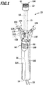
- a surgical instrument 10 for connecting body tissue comprises an elongated shaft 12 which defines a longitudinal axis 14. Proximal mineral of the shaft 12 connects to this a shaft-shaped grip portion 16, which extends approximately over half of a total length of the instrument 10. From a proximal end 18 of the handle portion 16 protrudes a connecting line 20, with which the instrument 10 with a power supply, not shown in the figures, for example, an RF generator, can be connected.
- a power supply not shown in the figures, for example, an RF generator
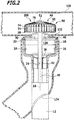
- the shaft 12 widens to a distal end 22 in the outer diameter substantially in one stage, so that a starting from the end 22 short, cylindrical receiving space 24 is formed, which is open in the distal direction.
- a sleeve-shaped electrode 28 is inserted into the receiving space 24 adjacent to an inner wall 26 of the same, which defines an electrode surface 30 inclined in the direction of the longitudinal axis 14.
- the electrode 28 is connected in a manner not shown electrically conductively connected to the connecting line 20.
- an inner shaft 32 is arranged in this, which extends approximately to the proximal end of the receiving space 24. It defines a channel 34.
- a cover 36 coats the receiving space 24 proximally, leaving only the channel 34 open.
- a rod-shaped first force transmission element 38 is guided longitudinally displaceable, which is surrounded by a second, sleeve-shaped force transmission element 40.
- the power transmission members 38 and 40 are movable relative to each other parallel to the longitudinal axis 14.
- a first tool element 48 of the instrument 10 is formed by the end 22 with the electrode 28.
- a distal end 42 of the first force transmission member 38 engages positively in a recess 44 of a second tool element 46 which is open in the proximal direction.
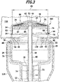
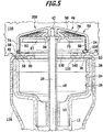
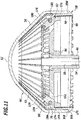
- the second tool element 46 is designed in the form of a kind of cover, which has a slightly convexly pointing in the distal direction curved end surface 50 with a blunt, rounded tip 52.
- the end face 50 spaced from the longitudinal axis 14, merges into an annular side wall 54 which, in an operating and approaching position of the instrument 10, is concentric with the longitudinal axis 14.
- a proximally facing end face 56 of the side wall 54 is concavely curved and serves to receive and fix an electrode 58 of the second tool element 46, which is in the form of an electrode ring 60.
- the electrode ring 60 is hollow and defines an electrode ring channel 62.
- the electrode ring 60 is not self-contained but is separated by a slot 64 so that facing ends 66 and 68 are slightly spaced apart.
- an electrode ring compensation element 70 is used, which connects the two ends 66 and 68 of the slotted electrode ring 60 together.
- the overall self-contained annular electrode 58 is formed, which has two different outer diameters, namely a larger one defined by an outer diameter of the electrode ring 60, and a smaller outer diameter between the ends 66 and 68 which is defined by an outer diameter of the electrode ring compensation element 70.
- the second tool element 46 is provided, starting from the end wall 54, with a plurality of radial slots 72 which are distributed uniformly over a circumference of the second tool element 46. In this way, at the tip 52 held together, extending therefrom in the radial direction and along the side wall 54 in the proximal direction extending tool element members 74, which have substantially the shape of an arm.
- the second tool member 46 is made of a plastic, forming part of the end face 50 forming portions 76 biasing members 78 a generally designated by the reference numeral 80 biasing means 80. This serves the purpose of biasing the second tool member 46 against a total of the Reference numeral 82 designated retaining device.
- the retaining device 82 comprises a retaining disk 84 extending essentially transversely to the longitudinal axis 14 and fixedly connected to the second power transmission member 40.
- Retaining disc 84 defines a maximum outer diameter 86 and is fitted with an annular sleeve-like cutting element 88 which concentrically surrounds longitudinal axis 14 and has a proximally facing cutting edge 90 which is self-contained.
- the cutter 88 thus forms part of the retainer 84.
- the retainer disk 84 and cutter 88 together form a stop member 87 which defines a stop for the tool member members 74 which acts radially away from the longitudinal axis 14. Overall, such a folding mechanism 200 is formed for quasi opening and closing of the second tool member 46 similar to an umbrella.
- the tool element members 74 are slightly spread in the radial direction, so that the retainer 82 is coming from the proximal inserted into the tool element 46 completely.
- the cutting edge 90 is set back somewhat in the distal direction relative to the electrode 58, so that the most projecting part of the second tool element 46 is the electrode 58.
- Inner surfaces 92 of the tool element links 74 which thus form part of the side wall 54, are biased against the retainer 82 due to the spreading, namely against the cutting element 88 and the retaining disc 84. Movement of free ends 94 of the tool element links 74 in the direction of the longitudinal axis 14 is thus prevented by the retainer 82.
- the instrument 10 further comprises an actuating mechanism 96 with a first actuating element 98 in the form of a helical gear 100, which concentrically surrounds the longitudinal axis 14 and is rotatably mounted about the longitudinal axis 14 in a housing defined by the grip region 16.
- the helical gear 100 is in operative connection with an outer diameter thickened portion 104 of the first power transmission member 38, which carries a screw thread 106. This makes it possible to move the first force transmission member 38 in the distal or in the proximal direction by rotation of the helical gear 100 about the longitudinal axis 14. Movement in the distal direction increases a distance between the electrodes 28 and 58, a movement of the first force transmission member in the proximal direction moves the electrode 58 in the direction of the electrode 28.
- the actuating mechanism 96 further includes a second actuator 108, which is in the form of a symmetrically formed handlebar assembly 110.
- Two first link 112 are laterally offset from the longitudinal axis 14 to pivot about this and parallel to each other pivot axes on the housing 102.
- Free ends 114 of the links 112 are in turn pivotally mounted on a respective further link 116.
- Two free ends of the links 116 are pivotally coupled together and the second power transmission member 40 to a the Slightly offset from the other free ends 122 toward the ends 114 are mounted to the handlebar 116 pivotable about parallel to the pivot axis 120 extending pivot axes. Free, facing away from the longitudinal axis ends 122 of the handlebar 116 form actuators for actuating the second actuator 108th
- the second vessel 126 is opened by a small incision 130.
- an opening is created by a second incision 134 slightly away from its end 132.
- the distal end of the instrument 10 is advanced with the second tooling element 46, which initially occupies the operative position described above and is biased by the retainer 82, inserted through the second incision 134 into the first vessel 126 until the second tooling element 46 exits the end 132 protrudes.
- the end 132 is laid inwardly over the electrode 28.
- the instrument 10 on which the first vessel 126 is retained in the manner described, is inserted with the second tooling element 46 through the first incision 130 into the second vessel 128.
- This is schematically in FIG. 2 shown.
- the vessels 126 and 128 are aligned so that the end 132 of the first vessel 126 covers the first incision 130 of the second vessel 128 as concentrically as possible.
- two layers of tissue are superimposed, as shown schematically in FIG. 3 shown.
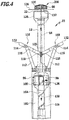
- the helical gear 110 For connecting the superimposed tissue parts, the helical gear 110, as in FIG. 4 shown schematically, rotated in the direction of arrow 136, so that the first power transmission member 38 is moved in the direction of the arrow 138 in the proximal direction.
- the two tissue layers abut against each other and are connected to each other by applying an RF current to the electrodes 28 and 58.
- the connection takes place, as it were, by welding the vessels 126 and 128, since proteins contained in the vessels 126 and 128 by the targeted flow of current through the electrodes 28 and 58 are heated to such an extent that they bond together and form a permanent and immediately loadable connection along an inward flow closed annular junction 140 between the electrodes 28 and 58 produce.
- the instrument 10 can be withdrawn again.
- the instrument 10 is first transferred from the approach position to the distance position. This is done by operating the second actuator 108, namely by the ends 122 are pivoted toward each other in the direction of the arrows 124.
- the second force transmission member 40 in the proximal direction, ie in the direction of the arrow 142, as shown schematically in FIG FIG. 7
- the retainer 82 held on the second power transmission member 40 is also moved in the proximal direction.
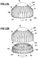
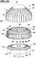
- the retaining device 82 releases the second tool element 46, in particular free ends 150 of the tool element links 74, so that they can be moved radially on the longitudinal axis 14 by the biasing elements 78 , This reduces a first distance 146, which is defined by the slot 72 in the operating position, as shown schematically in FIG. 9a shown at a smaller distance 148 in the distance position, as shown schematically in FIG. 9b is shown.
- a circumferential line of the electrode 58 decreases from an approaching circumference 152 in the operating or approach position, as shown schematically in FIG. 9a is drawn into a range of withdrawal in the distance position, as shown schematically in FIG. 9b is shown.
- the second tool element 46 can be moved from the operating position in which it can be brought into the approach position into a removal position in which the retraction circumference 154 defined by the electrode 58 is shorter, that is, the approximation circumference 152 defined by the electrode 58 in the approach position.
- the electrode 58 is thus variable in its scope.
- a first tool circumference line 156 defined by the second tool element 46 in the distance position is shorter than a second tool circumference line 158 defined by the second tool element 46 in the operating position, as shown schematically in FIGS. 9a and 9b is shown.
- electrode ring 60 with electrode ring compensation element 70 it would also be conceivable as an unclaimed alternative not to form the electrode 58 continuously, but to form the remaining end face areas at the distal ends 150 of the tool element members 74 in an electrically conductive manner or to arrange electrode ring sections there.
- the electrode 58 would then be a A plurality of electrode ring sections which are separated by the slots 72.
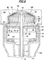
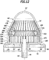
- FIGS. 10a to 12 schematically an alternative, unclaimed embodiment of a second tool element is shown and generally provided with the reference numeral 46 '.
- the second tool element 46 ' differs from the second tool element 46 substantially by the structure of the electrode 58' and the biasing device 80 '.
- the retainer 82 ' is substantially identical to the retainer 82. Differences are merely in the formation of the retainer disc 84' which includes a plurality of radially oriented and distally facing ribs 160. Between each two ribs 160, a receptacle 162 which is open in the distal direction is formed, in which an electrode element 164 is inserted in the operating or approach position.
- the electrode elements 164 are kept spaced apart in the circumferential direction.
- the electrode elements 164 are essentially L-shaped and have at their distal end a projection 166 projecting away from the longitudinal axis 14 in the radial direction, which forms a stop face 168 pointing in the distal direction for the ends 150 'of the tool element links 74'.
- the projection 166 further defines an electrode surface 170 which is inclined outwardly relative to the longitudinal axis 14 '.
- a portion 172 of the tool element member 74' In the operating position extends parallel to the longitudinal axis 14 'and parallel to the cutting element 88, a portion 172 of the tool element member 74'.
- the section 172 is adjoined by a section 174 directed transversely thereto and in the radial direction on the longitudinal axis 14 ', which section in turn is inclined in an angle of about 45 ° relative to the longitudinal axis 14' and pointing in the direction of the point 52 ' Section 176 passes.
- a free end 178 defined by the portion 176 has a recess 180 opened towards the tip 52 '.
- a further recess 182 is formed, which is open in the radial direction away from the longitudinal axis 14.
- a first elastic ring 184 is inserted and held non-positively and / or positively.
- a second elastic ring 186 which is stretched in the operating position, is inserted into the recesses 182. It serves to exert a tensile force on the electrode elements 164 in the operating position in order to keep the electrode elements 164 biasing in the direction of the longitudinal axis 14 against the retaining device 82 '.
- the ring 186 thus forms a biasing member 78 '.
- the electrode elements 164 are preferably formed from an electrically conductive material or coated electrically conductive.
- the ring 184 is preferably also made of an electrically conductive material, so that all electrode elements are electrically conductively connected to each other by means of the electrode ring 184.
- the ring 186 may optionally also be designed to be electrically conductive. However, it can also be made of an elastic plastic ring, for example.
- a cutting plane defined by the cutting edge 90 may be inclined relative to the longitudinal axis 14 '. This may not only be provided at the retainer 82 ', but may also be provided at the retainer 82.
- the operation of the instrument 10 is the same regardless of whether a second tool element 46 or a second tool element 46 'is provided.
- the retainer 82' is moved in an analogous manner in the proximal direction, so that the ring 186, the electrode elements 164 toward the Can move longitudinal axis 14 towards. It is thereby achieved that both a tool circumference line defined by the second tool element 46 'and a circumferential line defined by the electrode 58' in the approach position are each significantly longer than in the distance position.
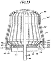
- FIG. 13 Another unclaimed alternative embodiment of a second tool element is shown in FIG. 13 shown schematically and generally provided with the reference numeral 46 '. It differs from the second tooling member 46 essentially in that free end 150 "of the tool member members 74" are bent inwardly three times, so that a radially extending portion 190 is first formed on the sidewall 54 ", a thereto adjacent, parallel to the longitudinal axis 14 extending in the distal direction portion 192 and a distal and radial inclined portion 194, which simultaneously forms the free end 150 ".
- Sections 190, 192 and 194 thus effectively define a receptacle 196 for an electrode ring 60 ", for example, which may be self-contained and made entirely or partially of nitinol, thus exhibiting an elasticity of up to about 8%. It thus forms at the same time the biasing member 78 "of a generally designated by the reference numeral 80 biasing means.
- the second tool element 46 " is in FIG. 13 shown schematically in the operating position.
- the sections 192 are in the operating position on the retainer 82, which is identical to that in connection with the Figures 1 to 9b described retaining means 82 is formed.
- the tool member members 74 "are released and the electrode ring 60" can contract to define an electrode line defined by the electrode 58 "at the transition from the Shortening the approach position to the distance position, so a folding mechanism of 200 " designed to virtually open and close the second tool element 46 "similar to an umbrella.
- FIG. 14 1 schematically shows another embodiment of a second tool element and is generally designated by the reference numeral 46 "'. It differs from the second tool element 46 essentially in that the slots 72"' separating the tool element links 74 "'are not in the radial direction from the longitudinal axis 14 are oriented away, but curved away from the longitudinal axis 14 extend away, so that the in FIG. 14
- the second tool element 46 '' may be provided with an electrode 58, in particular similar to the second tool element 46. It then allows, like the second tool elements 46, 46 'and 46 ", also that a first tool circumference line defined by the second tool element 46"' in the distance position is shorter than a second tool circumference line defined by the second tool element in the operating position.
- the second tool element 46 ' likewise makes it possible to bring it from the operating position in which it can be brought into the approach position into a removal position in which distance position a retraction circumferential line defined by the electrode 58 is shorter than that of the electrode 58
- a folding mechanism 200 "' is formed so as to virtually open and close the second tool element 46"' similar to an umbrella in the approach position.
- the electrodes 28 and 58 are each electrically conductively connected to the connection line 20. Preferably, they are electrically isolated from each other. It is easily possible to realize an electrical supply line to the electrode 58 in particular via the force transmission members 38 and 40 and to the second tool elements 46, 46 ', 46 "and 46"' and to the retainers 82, 82 'and 82 "accordingly provide conductive connections to the To be able to apply an HF current to electrodes 28 and 58 or 58 '.
Landscapes
- Health & Medical Sciences (AREA)
- Surgery (AREA)
- Life Sciences & Earth Sciences (AREA)
- Engineering & Computer Science (AREA)
- Biomedical Technology (AREA)
- Nuclear Medicine, Radiotherapy & Molecular Imaging (AREA)
- Heart & Thoracic Surgery (AREA)
- Medical Informatics (AREA)
- Molecular Biology (AREA)
- Animal Behavior & Ethology (AREA)
- General Health & Medical Sciences (AREA)
- Public Health (AREA)
- Veterinary Medicine (AREA)
- Otolaryngology (AREA)
- Plasma & Fusion (AREA)
- Physics & Mathematics (AREA)
- Surgical Instruments (AREA)
Applications Claiming Priority (2)
| Application Number | Priority Date | Filing Date | Title |
|---|---|---|---|
| DE102011055236A DE102011055236A1 (de) | 2011-11-10 | 2011-11-10 | Chirurgisches Instrument |
| PCT/EP2012/071941 WO2013068354A1 (de) | 2011-11-10 | 2012-11-06 | Anastomosegerät mit kollabierbarem distalem kopfelement |
Publications (2)
| Publication Number | Publication Date |
|---|---|
| EP2775941A1 EP2775941A1 (de) | 2014-09-17 |
| EP2775941B1 true EP2775941B1 (de) | 2019-01-09 |
Family
ID=47178647
Family Applications (1)
| Application Number | Title | Priority Date | Filing Date |
|---|---|---|---|
| EP12786922.0A Active EP2775941B1 (de) | 2011-11-10 | 2012-11-06 | Anastomosegerät mit kollabierbarem distalem kopfelement |
Country Status (7)
| Country | Link |
|---|---|
| US (2) | US9820804B2 (enExample) |
| EP (1) | EP2775941B1 (enExample) |
| JP (1) | JP6039679B2 (enExample) |
| CN (1) | CN103930050B (enExample) |
| DE (1) | DE102011055236A1 (enExample) |
| RU (1) | RU2014123506A (enExample) |
| WO (1) | WO2013068354A1 (enExample) |
Families Citing this family (8)
| Publication number | Priority date | Publication date | Assignee | Title |
|---|---|---|---|---|
| DE102011055236A1 (de) * | 2011-11-10 | 2013-05-16 | Aesculap Ag | Chirurgisches Instrument |
| DE102015205056A1 (de) * | 2015-03-20 | 2016-09-22 | Aesculap Ag | Chirurgisches Gewebefusionsinstrument und Stützstruktur hierfür |
| US10299795B2 (en) * | 2016-04-28 | 2019-05-28 | Mayo Foundation For Medical Education And Research | Devices and methods for esophageal lengthening and anastomosis formation |
| NL2017917B1 (en) * | 2016-12-02 | 2018-06-18 | Implican B V | Surgical method and instrument for performing anastomosis |
| CN108113746A (zh) * | 2017-11-16 | 2018-06-05 | 上海理工大学 | 射频能量焊接吻合电极及应用 |
| US11737745B2 (en) | 2018-10-24 | 2023-08-29 | Mayo Foundation For Medical Education And Research | Medical devices and methods for body conduit lengthening and anastomosis formation |
| KR102838761B1 (ko) * | 2019-09-13 | 2025-07-28 | 얼리비언트 메디컬 인코포레이티드 | 문합을 형성하기 위한 시스템, 장치 및 방법 |
| CN111248963B (zh) * | 2020-01-20 | 2021-02-26 | 常州市中医医院 | 一种腹腔镜用伞型吻合器 |
Family Cites Families (14)
| Publication number | Priority date | Publication date | Assignee | Title |
|---|---|---|---|---|
| US4700703A (en) * | 1986-03-27 | 1987-10-20 | Semion Resnick | Cartridge assembly for a surgical stapling instrument |
| US4893622A (en) | 1986-10-17 | 1990-01-16 | United States Surgical Corporation | Method of stapling tubular body organs |
| US20020025243A1 (en) * | 2001-02-02 | 2002-02-28 | Heck Christopher Francis | Surgical stapling instrument and method thereof |
| US6699245B2 (en) * | 2001-02-05 | 2004-03-02 | A-Med Systems, Inc. | Anastomosis system and related methods |
| JP2007516730A (ja) * | 2003-06-20 | 2007-06-28 | タイコ・ヘルスケア・グループ・リミテッド・パートナーシップ | 外科用ステープリング装置 |
| US20060111704A1 (en) * | 2004-11-22 | 2006-05-25 | Rox Medical, Inc. | Devices, systems, and methods for energy assisted arterio-venous fistula creation |
| US20080243121A1 (en) * | 2007-04-02 | 2008-10-02 | Tomoyuki Takashino | Curative treatment system, curative treatment device, and treatment method for living tissue using energy |
| US20090048589A1 (en) * | 2007-08-14 | 2009-02-19 | Tomoyuki Takashino | Treatment device and treatment method for living tissue |
| DE102009002768A1 (de) * | 2009-04-30 | 2010-11-04 | Celon Ag Medical Instruments | Materialschicht und Elektrochirurgiesystem für die elektrochirurgische Gewebefusion |
| DE102009027813A1 (de) * | 2009-07-17 | 2011-01-27 | Celon Ag Medical Instruments | Anastomosering und Anastomoseringanordnung |
| DE102009059195A1 (de) * | 2009-12-17 | 2011-06-22 | Aesculap AG, 78532 | Chirurgisches System zum Verbinden von Körpergewebe und Verfahren zum Abtrennen überstehenden Gewebes |
| DE102009059192A1 (de) * | 2009-12-17 | 2011-06-22 | Aesculap AG, 78532 | Chirurgisches System und Steuerungsverfahren für ein chirurgisches Instrument und Verfahren zum Verbinden von Körpergewebeteilen |
| DE102009059196A1 (de) | 2009-12-17 | 2011-06-22 | Aesculap AG, 78532 | Chirurgisches System zum Verbinden von Körpergewebe |
| DE102011055236A1 (de) * | 2011-11-10 | 2013-05-16 | Aesculap Ag | Chirurgisches Instrument |
-
2011
- 2011-11-10 DE DE102011055236A patent/DE102011055236A1/de not_active Withdrawn
-
2012
- 2012-11-06 US US14/356,250 patent/US9820804B2/en active Active
- 2012-11-06 CN CN201280055245.3A patent/CN103930050B/zh active Active
- 2012-11-06 WO PCT/EP2012/071941 patent/WO2013068354A1/de not_active Ceased
- 2012-11-06 JP JP2014540423A patent/JP6039679B2/ja active Active
- 2012-11-06 EP EP12786922.0A patent/EP2775941B1/de active Active
- 2012-11-06 RU RU2014123506/14A patent/RU2014123506A/ru not_active Application Discontinuation
-
2017
- 2017-10-16 US US15/784,634 patent/US11141211B2/en active Active
Non-Patent Citations (1)
| Title |
|---|
| None * |
Also Published As
| Publication number | Publication date |
|---|---|
| US20140309634A1 (en) | 2014-10-16 |
| JP6039679B2 (ja) | 2016-12-07 |
| DE102011055236A1 (de) | 2013-05-16 |
| US11141211B2 (en) | 2021-10-12 |
| EP2775941A1 (de) | 2014-09-17 |
| RU2014123506A (ru) | 2015-12-20 |
| US9820804B2 (en) | 2017-11-21 |
| JP2015504330A (ja) | 2015-02-12 |
| CN103930050B (zh) | 2017-10-13 |
| US20180036063A1 (en) | 2018-02-08 |
| CN103930050A (zh) | 2014-07-16 |
| WO2013068354A1 (de) | 2013-05-16 |
Similar Documents
| Publication | Publication Date | Title |
|---|---|---|
| EP2775941B1 (de) | Anastomosegerät mit kollabierbarem distalem kopfelement | |
| DE69632872T2 (de) | Spannbackenanordnung für endoskopische instrumente | |
| DE69532711T2 (de) | Rotierbares gabelgelenk für ein flexibles mikrochirurgisches instrument | |
| DE69632547T2 (de) | Trokaranordnung | |
| EP2911595B1 (de) | Anastomoseinstrument mit schwenkbarem amboss | |
| DE19704580C2 (de) | Chirurgischer Fadenschneider | |
| EP2890307B1 (de) | Elektrochirurgisches instrument zur herstellung einer end-zu-end-anastomose | |
| DE29909688U1 (de) | Instrument zur chirurgischen Ligation | |
| EP1083834B1 (de) | Vorrichtung zum schaffen eines transkutanen zuganges zu einem körperinneren hohlorgan | |
| WO2018046534A1 (de) | Medizinisches instrument mit reinigungsspalt im verschlussbereich | |
| EP2710973B1 (de) | Koagulationselektrode | |
| EP3294157B1 (de) | Chirurgisches instrument mit abstandhaltendem schwenkelement | |
| DE102013110171A1 (de) | Medizinisches Instrument | |
| EP2725988B1 (de) | Trokarsystem | |
| EP4091558B1 (de) | Endoskopisches instrument sowie schaft und instrumenteneinsatz für ein endoskopisches instrument | |
| WO2015165822A1 (de) | Maulteil für ein chirurgisches rohrschaft-instrument | |
| EP3439568B1 (de) | Schaft für ein medizinisches instrument sowie medizinisches instrument, insbesondere mono- oder bipolares medizinisches instrument | |
| DE19915062C1 (de) | Chirurgisches Instrument | |
| DE102007030874B4 (de) | Chirurgisches Instrument | |
| DE102012103501A1 (de) | Chirurgisches Gerät und bogenförmige Nadel dafür | |
| DE202011051933U1 (de) | Chirurgisches Instrument | |
| DE202007009315U1 (de) | Chirurgisches Instrument | |
| DE20309776U1 (de) | Chirurgisches Instrument | |
| DE102023134397A1 (de) | Chirurgisches minimalinvasive Instrument | |
| DE102017100321A1 (de) | Elektrochirurgische Vorrichtung |
Legal Events
| Date | Code | Title | Description |
|---|---|---|---|
| PUAI | Public reference made under article 153(3) epc to a published international application that has entered the european phase |
Free format text: ORIGINAL CODE: 0009012 |
|
| 17P | Request for examination filed |
Effective date: 20140603 |
|
| AK | Designated contracting states |
Kind code of ref document: A1 Designated state(s): AL AT BE BG CH CY CZ DE DK EE ES FI FR GB GR HR HU IE IS IT LI LT LU LV MC MK MT NL NO PL PT RO RS SE SI SK SM TR |
|
| DAX | Request for extension of the european patent (deleted) | ||
| 17Q | First examination report despatched |
Effective date: 20160603 |
|
| STAA | Information on the status of an ep patent application or granted ep patent |
Free format text: STATUS: EXAMINATION IS IN PROGRESS |
|
| GRAP | Despatch of communication of intention to grant a patent |
Free format text: ORIGINAL CODE: EPIDOSNIGR1 |
|
| STAA | Information on the status of an ep patent application or granted ep patent |
Free format text: STATUS: GRANT OF PATENT IS INTENDED |
|
| INTG | Intention to grant announced |
Effective date: 20180627 |
|
| GRAS | Grant fee paid |
Free format text: ORIGINAL CODE: EPIDOSNIGR3 |
|
| GRAA | (expected) grant |
Free format text: ORIGINAL CODE: 0009210 |
|
| STAA | Information on the status of an ep patent application or granted ep patent |
Free format text: STATUS: THE PATENT HAS BEEN GRANTED |
|
| AK | Designated contracting states |
Kind code of ref document: B1 Designated state(s): AL AT BE BG CH CY CZ DE DK EE ES FI FR GB GR HR HU IE IS IT LI LT LU LV MC MK MT NL NO PL PT RO RS SE SI SK SM TR |
|
| REG | Reference to a national code |
Ref country code: GB Ref legal event code: FG4D Free format text: NOT ENGLISH |
|
| REG | Reference to a national code |
Ref country code: CH Ref legal event code: EP Ref country code: AT Ref legal event code: REF Ref document number: 1086342 Country of ref document: AT Kind code of ref document: T Effective date: 20190115 |
|
| REG | Reference to a national code |
Ref country code: DE Ref legal event code: R096 Ref document number: 502012014152 Country of ref document: DE |
|
| REG | Reference to a national code |
Ref country code: IE Ref legal event code: FG4D Free format text: LANGUAGE OF EP DOCUMENT: GERMAN |
|
| REG | Reference to a national code |
Ref country code: NL Ref legal event code: MP Effective date: 20190109 |
|
| REG | Reference to a national code |
Ref country code: LT Ref legal event code: MG4D |
|
| PG25 | Lapsed in a contracting state [announced via postgrant information from national office to epo] |
Ref country code: NL Free format text: LAPSE BECAUSE OF FAILURE TO SUBMIT A TRANSLATION OF THE DESCRIPTION OR TO PAY THE FEE WITHIN THE PRESCRIBED TIME-LIMIT Effective date: 20190109 |
|
| PG25 | Lapsed in a contracting state [announced via postgrant information from national office to epo] |
Ref country code: PT Free format text: LAPSE BECAUSE OF FAILURE TO SUBMIT A TRANSLATION OF THE DESCRIPTION OR TO PAY THE FEE WITHIN THE PRESCRIBED TIME-LIMIT Effective date: 20190509 Ref country code: ES Free format text: LAPSE BECAUSE OF FAILURE TO SUBMIT A TRANSLATION OF THE DESCRIPTION OR TO PAY THE FEE WITHIN THE PRESCRIBED TIME-LIMIT Effective date: 20190109 Ref country code: LT Free format text: LAPSE BECAUSE OF FAILURE TO SUBMIT A TRANSLATION OF THE DESCRIPTION OR TO PAY THE FEE WITHIN THE PRESCRIBED TIME-LIMIT Effective date: 20190109 Ref country code: NO Free format text: LAPSE BECAUSE OF FAILURE TO SUBMIT A TRANSLATION OF THE DESCRIPTION OR TO PAY THE FEE WITHIN THE PRESCRIBED TIME-LIMIT Effective date: 20190409 Ref country code: PL Free format text: LAPSE BECAUSE OF FAILURE TO SUBMIT A TRANSLATION OF THE DESCRIPTION OR TO PAY THE FEE WITHIN THE PRESCRIBED TIME-LIMIT Effective date: 20190109 Ref country code: SE Free format text: LAPSE BECAUSE OF FAILURE TO SUBMIT A TRANSLATION OF THE DESCRIPTION OR TO PAY THE FEE WITHIN THE PRESCRIBED TIME-LIMIT Effective date: 20190109 Ref country code: FI Free format text: LAPSE BECAUSE OF FAILURE TO SUBMIT A TRANSLATION OF THE DESCRIPTION OR TO PAY THE FEE WITHIN THE PRESCRIBED TIME-LIMIT Effective date: 20190109 |
|
| PG25 | Lapsed in a contracting state [announced via postgrant information from national office to epo] |
Ref country code: BG Free format text: LAPSE BECAUSE OF FAILURE TO SUBMIT A TRANSLATION OF THE DESCRIPTION OR TO PAY THE FEE WITHIN THE PRESCRIBED TIME-LIMIT Effective date: 20190409 Ref country code: RS Free format text: LAPSE BECAUSE OF FAILURE TO SUBMIT A TRANSLATION OF THE DESCRIPTION OR TO PAY THE FEE WITHIN THE PRESCRIBED TIME-LIMIT Effective date: 20190109 Ref country code: IS Free format text: LAPSE BECAUSE OF FAILURE TO SUBMIT A TRANSLATION OF THE DESCRIPTION OR TO PAY THE FEE WITHIN THE PRESCRIBED TIME-LIMIT Effective date: 20190509 Ref country code: LV Free format text: LAPSE BECAUSE OF FAILURE TO SUBMIT A TRANSLATION OF THE DESCRIPTION OR TO PAY THE FEE WITHIN THE PRESCRIBED TIME-LIMIT Effective date: 20190109 Ref country code: GR Free format text: LAPSE BECAUSE OF FAILURE TO SUBMIT A TRANSLATION OF THE DESCRIPTION OR TO PAY THE FEE WITHIN THE PRESCRIBED TIME-LIMIT Effective date: 20190410 Ref country code: HR Free format text: LAPSE BECAUSE OF FAILURE TO SUBMIT A TRANSLATION OF THE DESCRIPTION OR TO PAY THE FEE WITHIN THE PRESCRIBED TIME-LIMIT Effective date: 20190109 |
|
| REG | Reference to a national code |
Ref country code: DE Ref legal event code: R097 Ref document number: 502012014152 Country of ref document: DE |
|
| PG25 | Lapsed in a contracting state [announced via postgrant information from national office to epo] |
Ref country code: IT Free format text: LAPSE BECAUSE OF FAILURE TO SUBMIT A TRANSLATION OF THE DESCRIPTION OR TO PAY THE FEE WITHIN THE PRESCRIBED TIME-LIMIT Effective date: 20190109 Ref country code: RO Free format text: LAPSE BECAUSE OF FAILURE TO SUBMIT A TRANSLATION OF THE DESCRIPTION OR TO PAY THE FEE WITHIN THE PRESCRIBED TIME-LIMIT Effective date: 20190109 Ref country code: SK Free format text: LAPSE BECAUSE OF FAILURE TO SUBMIT A TRANSLATION OF THE DESCRIPTION OR TO PAY THE FEE WITHIN THE PRESCRIBED TIME-LIMIT Effective date: 20190109 Ref country code: CZ Free format text: LAPSE BECAUSE OF FAILURE TO SUBMIT A TRANSLATION OF THE DESCRIPTION OR TO PAY THE FEE WITHIN THE PRESCRIBED TIME-LIMIT Effective date: 20190109 Ref country code: AL Free format text: LAPSE BECAUSE OF FAILURE TO SUBMIT A TRANSLATION OF THE DESCRIPTION OR TO PAY THE FEE WITHIN THE PRESCRIBED TIME-LIMIT Effective date: 20190109 Ref country code: DK Free format text: LAPSE BECAUSE OF FAILURE TO SUBMIT A TRANSLATION OF THE DESCRIPTION OR TO PAY THE FEE WITHIN THE PRESCRIBED TIME-LIMIT Effective date: 20190109 Ref country code: EE Free format text: LAPSE BECAUSE OF FAILURE TO SUBMIT A TRANSLATION OF THE DESCRIPTION OR TO PAY THE FEE WITHIN THE PRESCRIBED TIME-LIMIT Effective date: 20190109 |
|
| PLBE | No opposition filed within time limit |
Free format text: ORIGINAL CODE: 0009261 |
|
| STAA | Information on the status of an ep patent application or granted ep patent |
Free format text: STATUS: NO OPPOSITION FILED WITHIN TIME LIMIT |
|
| PG25 | Lapsed in a contracting state [announced via postgrant information from national office to epo] |
Ref country code: SM Free format text: LAPSE BECAUSE OF FAILURE TO SUBMIT A TRANSLATION OF THE DESCRIPTION OR TO PAY THE FEE WITHIN THE PRESCRIBED TIME-LIMIT Effective date: 20190109 |
|
| 26N | No opposition filed |
Effective date: 20191010 |
|
| PG25 | Lapsed in a contracting state [announced via postgrant information from national office to epo] |
Ref country code: SI Free format text: LAPSE BECAUSE OF FAILURE TO SUBMIT A TRANSLATION OF THE DESCRIPTION OR TO PAY THE FEE WITHIN THE PRESCRIBED TIME-LIMIT Effective date: 20190109 |
|
| PG25 | Lapsed in a contracting state [announced via postgrant information from national office to epo] |
Ref country code: TR Free format text: LAPSE BECAUSE OF FAILURE TO SUBMIT A TRANSLATION OF THE DESCRIPTION OR TO PAY THE FEE WITHIN THE PRESCRIBED TIME-LIMIT Effective date: 20190109 |
|
| REG | Reference to a national code |
Ref country code: CH Ref legal event code: PL |
|
| PG25 | Lapsed in a contracting state [announced via postgrant information from national office to epo] |
Ref country code: CH Free format text: LAPSE BECAUSE OF NON-PAYMENT OF DUE FEES Effective date: 20191130 Ref country code: MC Free format text: LAPSE BECAUSE OF FAILURE TO SUBMIT A TRANSLATION OF THE DESCRIPTION OR TO PAY THE FEE WITHIN THE PRESCRIBED TIME-LIMIT Effective date: 20190109 Ref country code: LI Free format text: LAPSE BECAUSE OF NON-PAYMENT OF DUE FEES Effective date: 20191130 Ref country code: LU Free format text: LAPSE BECAUSE OF NON-PAYMENT OF DUE FEES Effective date: 20191106 |
|
| REG | Reference to a national code |
Ref country code: BE Ref legal event code: MM Effective date: 20191130 |
|
| PG25 | Lapsed in a contracting state [announced via postgrant information from national office to epo] |
Ref country code: IE Free format text: LAPSE BECAUSE OF NON-PAYMENT OF DUE FEES Effective date: 20191106 |
|
| PG25 | Lapsed in a contracting state [announced via postgrant information from national office to epo] |
Ref country code: BE Free format text: LAPSE BECAUSE OF NON-PAYMENT OF DUE FEES Effective date: 20191130 |
|
| REG | Reference to a national code |
Ref country code: AT Ref legal event code: MM01 Ref document number: 1086342 Country of ref document: AT Kind code of ref document: T Effective date: 20191106 |
|
| PG25 | Lapsed in a contracting state [announced via postgrant information from national office to epo] |
Ref country code: AT Free format text: LAPSE BECAUSE OF NON-PAYMENT OF DUE FEES Effective date: 20191106 |
|
| PG25 | Lapsed in a contracting state [announced via postgrant information from national office to epo] |
Ref country code: CY Free format text: LAPSE BECAUSE OF FAILURE TO SUBMIT A TRANSLATION OF THE DESCRIPTION OR TO PAY THE FEE WITHIN THE PRESCRIBED TIME-LIMIT Effective date: 20190109 |
|
| PG25 | Lapsed in a contracting state [announced via postgrant information from national office to epo] |
Ref country code: MT Free format text: LAPSE BECAUSE OF FAILURE TO SUBMIT A TRANSLATION OF THE DESCRIPTION OR TO PAY THE FEE WITHIN THE PRESCRIBED TIME-LIMIT Effective date: 20190109 Ref country code: HU Free format text: LAPSE BECAUSE OF FAILURE TO SUBMIT A TRANSLATION OF THE DESCRIPTION OR TO PAY THE FEE WITHIN THE PRESCRIBED TIME-LIMIT; INVALID AB INITIO Effective date: 20121106 |
|
| PG25 | Lapsed in a contracting state [announced via postgrant information from national office to epo] |
Ref country code: MK Free format text: LAPSE BECAUSE OF FAILURE TO SUBMIT A TRANSLATION OF THE DESCRIPTION OR TO PAY THE FEE WITHIN THE PRESCRIBED TIME-LIMIT Effective date: 20190109 |
|
| P01 | Opt-out of the competence of the unified patent court (upc) registered |
Effective date: 20230926 |
|
| PGFP | Annual fee paid to national office [announced via postgrant information from national office to epo] |
Ref country code: DE Payment date: 20251118 Year of fee payment: 14 |
|
| PGFP | Annual fee paid to national office [announced via postgrant information from national office to epo] |
Ref country code: GB Payment date: 20251120 Year of fee payment: 14 |
|
| PGFP | Annual fee paid to national office [announced via postgrant information from national office to epo] |
Ref country code: FR Payment date: 20251120 Year of fee payment: 14 |