EP2775914B1 - 3d intraoral measurements using optical multiline method - Google Patents
3d intraoral measurements using optical multiline method Download PDFInfo
- Publication number
- EP2775914B1 EP2775914B1 EP12847432.7A EP12847432A EP2775914B1 EP 2775914 B1 EP2775914 B1 EP 2775914B1 EP 12847432 A EP12847432 A EP 12847432A EP 2775914 B1 EP2775914 B1 EP 2775914B1
- Authority
- EP
- European Patent Office
- Prior art keywords
- pixels
- group
- image
- images
- multiline
- Prior art date
- Legal status (The legal status is an assumption and is not a legal conclusion. Google has not performed a legal analysis and makes no representation as to the accuracy of the status listed.)
- Not-in-force
Links
Images


Classifications
-
- A—HUMAN NECESSITIES
- A61—MEDICAL OR VETERINARY SCIENCE; HYGIENE
- A61C—DENTISTRY; APPARATUS OR METHODS FOR ORAL OR DENTAL HYGIENE
- A61C9/00—Impression cups, i.e. impression trays; Impression methods
- A61C9/004—Means or methods for taking digitized impressions
- A61C9/0046—Data acquisition means or methods
- A61C9/0053—Optical means or methods, e.g. scanning the teeth by a laser or light beam
- A61C9/006—Optical means or methods, e.g. scanning the teeth by a laser or light beam projecting one or more stripes or patterns on the teeth
-
- G—PHYSICS
- G06—COMPUTING OR CALCULATING; COUNTING
- G06T—IMAGE DATA PROCESSING OR GENERATION, IN GENERAL
- G06T7/00—Image analysis
- G06T7/50—Depth or shape recovery
- G06T7/521—Depth or shape recovery from laser ranging, e.g. using interferometry; from the projection of structured light
-
- G—PHYSICS
- G06—COMPUTING OR CALCULATING; COUNTING
- G06T—IMAGE DATA PROCESSING OR GENERATION, IN GENERAL
- G06T7/00—Image analysis
- G06T7/50—Depth or shape recovery
- G06T7/55—Depth or shape recovery from multiple images
-
- G—PHYSICS
- G06—COMPUTING OR CALCULATING; COUNTING
- G06T—IMAGE DATA PROCESSING OR GENERATION, IN GENERAL
- G06T2207/00—Indexing scheme for image analysis or image enhancement
- G06T2207/10—Image acquisition modality
- G06T2207/10016—Video; Image sequence
-
- G—PHYSICS
- G06—COMPUTING OR CALCULATING; COUNTING
- G06T—IMAGE DATA PROCESSING OR GENERATION, IN GENERAL
- G06T2207/00—Indexing scheme for image analysis or image enhancement
- G06T2207/10—Image acquisition modality
- G06T2207/10141—Special mode during image acquisition
- G06T2207/10152—Varying illumination
-
- G—PHYSICS
- G06—COMPUTING OR CALCULATING; COUNTING
- G06T—IMAGE DATA PROCESSING OR GENERATION, IN GENERAL
- G06T2207/00—Indexing scheme for image analysis or image enhancement
- G06T2207/30—Subject of image; Context of image processing
- G06T2207/30004—Biomedical image processing
- G06T2207/30036—Dental; Teeth
Definitions
- the disclosure relates generally to the field of surface shape imaging and more particularly relates to intraoral surface imaging and measurement.
- Optical 3-dimensional (3-D) measurement methods provide shape and depth information using images obtained from patterns of light directed onto a surface.
- Various types of imaging methods generate a series of light patterns and use focus or triangulation to detect changes in surface shape over the illuminated area.
- Fringe projection imaging uses patterned or structured light and triangulation to obtain surface contour information for structures of various types.
- fringe projection imaging a pattern of lines of an interference fringe or grating is projected toward the surface of an object from a given angle.
- the projected pattern from the surface is viewed from another angle as a contour image, taking advantage of triangulation in order to analyze surface information based on the appearance of contour lines.
- Phase shifting in which the projected pattern is incrementally spatially shifted for obtaining additional measurements at the new locations, is typically applied as part of fringe projection imaging, used in order to complete the contour mapping of the surface and to increase overall resolution in the contour image.
- Fringe projection imaging has been used for surface contour imaging of solid, highly opaque objects and has been used for imaging the surface contours for some portions of the human body and for obtaining detailed data about skin structure.
- a number of technical obstacles have prevented effective use of fringe projection imaging of the tooth.
- One particular challenge with dental surface imaging relates to tooth translucency.
- Translucent or semi-translucent materials in general are known to be particularly troublesome for fringe projection imaging.
- Subsurface scattering in translucent structures can reduce the overall signal-to-noise (S/N) ratio and shift the light intensity, causing inaccurate height data.
- Another issue relates to high levels of reflection for various tooth surfaces.
- Highly reflective materials, particularly hollowed reflective structures can reduce the dynamic range of this type of imaging.
- Teeth can be wet or dry at different times and along different surfaces and portions of surfaces. Tooth shape is often irregular, with sharp edges. As noted earlier, teeth interact with light in a complex manner. Light penetrating beneath the surface of the tooth tends to undergo scattering within the translucent tooth material. Moreover, reflection from opaque features beneath the tooth surface can occur, adding noise that degrades the sensed signal.
- a tooth contour imaging system applies a paint or reflective powder to the tooth surface prior to surface contour imaging.
- this added step enhances the opacity of the tooth and reduces the scattered light effects noted earlier.
- the step of applying a coating powder or liquid adds cost and time to the tooth contour imaging process. Because the thickness of the coating layer is often non-uniform over the entire tooth surface, measurement errors readily result. Further, the applied coating, while it facilitates contour imaging, can tend to mask other problems with the tooth and can thus reduce the overall amount of useful information that can be obtained.
- WO 2011 013 373 A1 discloses a measuring apparatus, which has a projection unit to project, onto an object, a first light pattern with light and dark portions, a second light pattern, which is smaller in distance between the light and dark portions than that of the first light pattern and has a boundary position between the light and dark portions common to the first light pattern, and a third light pattern in which the light and dark portions of the second light pattern are reversed to each other.
- the measuring apparatus also has an acquisition unit to capture images of the first, second and third light patterns on an object and a calculation unit configured to calculate the boundary position between the light and dark portions of the first captured image based on the second and the third captured image to measure the position of the object.
- US 2011 050 859 A discloses a method of forming at least one three dimensional (3D) color image of at least one object in a target space.
- the method comprises projecting, each of a plurality of projection cycles, a sequence comprising a plurality of gray coded light patterns, each colored in one of red green or blue, on a target space, capturing a plurality of two dimensional (2D) images of the target space during a plurality of acquisition cycles, each the acquisition cycle being timed to correspond with the projection of at least a sub sequence of the sequence, the sub sequence comprising red, green, and blue gray coded light patterns of the plurality of gray coded light patterns.
- US 6 754 370 B1 discloses a method for range scanning consists of projecting a sequence of radiation patterns onto a scene, capturing images of the scene, determining correspondences between image features and projection pattern features, and computing a range image of the scene by triangulation of the correspondences. Novel projection patterns allow tracking of pattern features between images, so that range images can be computed for moving scenes in real time.
- An object of the present invention is to advance the art of surface contour detection of teeth and related intraoral structures.
- Embodiments of the present invention provide 3-D surface information about a tooth by illuminating the tooth surface with an arrangement of light patterns that help to more closely map pixel locations on a digital imaging array with pixel locations from an illumination device.
- the present invention can be used with known illumination and imaging component arrangements and is adapted to help reduce ambiguity of sensed patterns when compared against conventional contour detection methods.
- a method for mapping a sensor pixel array to an illumination pixel array according to a surface of which a surface contour image is to be generated as set forth in claim 1 and an intraoral apparatus as set forth in claim 12 are provided. Further embodiments are inter alia disclosed in the dependent claims.
- the method for mapping a sensor pixel array to an illumination pixel array according to a surface of which a surface contour image is to be generated is executed at least in part on a computer and inter alia comprises: forming a group mapping by assigning each pixel in a plurality of pixels on the sensor array to a corresponding group of an ordered set of groups, wherein each group is defined as a set of p adjacent pixels on the illumination pixel array and each ordered set has k groups, by: projecting and recording a sequence of two or more group index images, wherein, with respect to each ordered set of k groups, each projected group index image has, in at least two of the groups, no illuminated pixels and in fewer than ( k-1) groups, has from 2 to ( p-1 ) adjacent illuminated pixels, and wherein the sequence of projected group index images uses illuminated pixels from each of the k groups; projecting and recording at least p multiline images onto the surface, wherein each multiline image projects a line within each group; correlating lines in
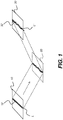
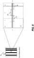
- the schematic diagram of Figure 1 shows, with the example of a single line of light L, how patterned light is used for obtaining surface contour information.
- a mapping is obtained as an illumination array 10 directs a pattern of light onto a surface 20 and a corresponding image of a line L' is formed on an imaging sensor array 30.
- Each pixel 32 on imaging sensor array 32 maps to a corresponding pixel 12 on illumination array 10 according to modulation by surface 20. Shifts in pixel position, as represented in Figure 1 , yield useful information about the contour of surface 20.
- the basic pattern shown in Figure 1 can be implemented in a number of ways, using a variety of illumination sources and sequences and using one or more different types of sensor arrays 30.
- Illumination array 10 can utilize any of a number of types of arrays used for light modulation, such as a liquid crystal array or digital micromirror array, such as that provided using the Digital Light Processor or DLP device from Texas Instruments, Dallas, TX. This type of spatial light modulator is used in the illumination path to change the light pattern as needed for the mapping sequence.
- a liquid crystal array or digital micromirror array such as that provided using the Digital Light Processor or DLP device from Texas Instruments, Dallas, TX. This type of spatial light modulator is used in the illumination path to change the light pattern as needed for the mapping sequence.
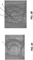
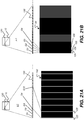
- Figures 2A and 2B show aspects of one problem with conventional approaches for using patterned light to obtain surface structure information from the human tooth.
- Figure 2A shows illumination with a single line of light 14 onto the tooth, with pronounced shifting of the illumination at the tooth edges. Projection of a single line in this manner, scanned across the tooth and imaged at numerous points during the scan, can provide accurate information about portions of the surface area; however, some information is lost even with this method, such as where line segments are separated from each other.
- Figure 2B shows surface imaging using a pattern with multiple lines of light. Where there are abrupt transitions along the surface, it can be difficult to positively identify the segments that correspond to each projected line and mismatches can easily occur, leading to inaccurate conclusions about surface characteristics. For example, it can be difficult to determine whether line segment 16 is from the same line of illumination as line segment 18 or adjacent line segment 24.
- Embodiments of the present invention address the problem of surface contour mapping using a sequence of projected images that help to better correlate pixels on the imaging sensor array with projected lines from the illumination array.
- embodiments of the present invention use an arrangement of binary images to group pixels on the imaging sensor array with corresponding pixels on the illumination pixel array.
- a group mapping is formed by assigning pixels on the sensor array to an ordered set of groups, each group having a fixed number of pixels.
- the group mapping can be stored as a particular data structure or may be otherwise represented in data that relates each pixel to a particular group structure, using mapping techniques well known to those skilled in the data representation arts.
- the terms "group map” and "group mapping” are considered to be equivalent, since the relationship of pixels and groups can be represented and stored in any of a number of ways.
- an image capture step 40 the operator positions the imaging apparatus and captures a series of images, as described subsequently.
- the images consist of a number n of binary patterns 46 and m binary patterns 48 and p multiline images 54 and can be captured in any order.
- a pixel assignment step 44 executes, in which pixels on the image sensor array are assigned to a group map or mapping that corresponds to pixels on the illumination array. Images for the group mapping are from binary patterns 46 and 48, described in more detail subsequently.
- An additional dark image 36, with no illumination, and flat image 38 with full frame illumination are also obtained to help in signal processing, as described subsequently.
- a set of p multiline images 54 is also obtained, from which peak locations, that is, locations of highest intensity, can be detected in a location detection step 50.
- a mapping step 60 then forms and stores the contour image in a memory, such as in a temporary display memory that is associated with a display monitor, for example.
- a binary pattern has one or more bright bands that are two or more pixels wide on illumination array 10.
- a multiline image has one or more bright bands that are one pixel wide on illumination array 10.
- the multiline image has at least one bright-to-dark or dark-to-bright transition within each group of pixels.
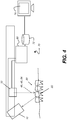
- the schematic diagram of Figure 4 shows an imaging apparatus 70 for projecting and imaging the binary patterns 46 and 48 and multiline images 54.
- a control logic processor 80 or other type of computer controls the operation of illumination array 10 and imaging sensor array 30.
- Image data from surface 20, such as from a tooth 22, is obtained from imaging sensor array 30 and stored in a memory 72.
- Control logic processor 80 processes the received image data and stores the mapping in memory 72.
- the resulting image from memory 72 is then optionally displayed on a display 74.
- Memory 72 may also include a display buffer.
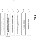
- a first binary pattern recording step 62 records at least n images from a first set of n binary patterns projected onto the surface, in which transitions between pixels occur only at group boundaries, as described subsequently. This set of n images is described as being "in-phase” with the group arrangement.
- a second binary pattern recording step 64 then records m binary patterns projected onto the surface, in which one or more transitions between pixels in each of the m patterns are offset from group boundaries, again described in more detail subsequently. This set of m images is described as being "out-of-phase" with the group arrangement, with at least one transition within a group.
- a dark and flat image recording step 65 then records dark field and flat field images.
- the combination of images recorded from recording steps 62, 64, and 65 are then used for forming the group map in pixel assignment step 44 of Figure 3 .
- a multiline image recording step 66 projects onto the surface and records at least p multiline images, as described in more detail subsequently.
- a correlation step 68 then correlates surface positions with pixel positions on image sensor array 30 as part of mapping step 60 in Figure 3 .
- An optional display step 82 then displays the surface contour obtained from the mapping.
- Figures 6 , 7 , and 8 show various aspects of the process for forming the group map according to an embodiment of the present invention.
- Figure 6 shows part of a row of pixels 32 on imaging sensor array 30 corresponding to positions on surface 20.
- Each group has a predetermined number p of adjacent pixels 32, with eight pixels 32 per group in the example mapping that is shown.
- Vertical dashed lines in Figures 6-8 indicate group boundaries. At a group boundary, wherein each group has p pixels numbered from 0 , 1, 2, ...
- FIG. 7 shows the first pattern.
- n images from a set of n binary patterns are projected from illumination array 10 in which each row is arranged according to groups.
- Representative eight-pixel groups G8, G7, G6, and G5 are shown, numbered in descending order from right to left in this example.
- binary patterns 46a and 46b Two of the n binary patterns 46a and 46b are shown, with binary 1, 0 representation shown for respective dark (off or 0)/bright (on or 1) bands that have transitions from bright to dark or, alternately, from dark to bright, at group boundaries.
- binary pattern 46b is the next binary pattern in sequence, changing only one bit from the binary pattern at 46a.
- the successive binary patterns are arranged in a sequence that emulates a Gray code, in which each successive pattern (x) changes by only one bit from the previous pattern (x-1).
- Bright bands in the binary patterns 46a and 46b corresponding with binary number 1 in Figures 7 and 8 , have a width that is in integer increments of a group of pixels, so that a bright band will be as wide as one, two, or more than two groups of pixels from the illuminator array.
- a bright band in the binary pattern 46a or 46b is 8, 16, 24, 32, or some other integer multiple of 8 pixels wide.
- the schematic diagram of Figure 8 shows projection of one of the second set of m binary patterns 48.
- one or more of the binary 0/1 or 1/0 transitions between pixels are offset from group boundaries.
- group G7 spans across the corresponding transition that is offset from its boundary with group G6.
- a transition is offset from the border of group G5, splitting pixels in this group into those on one side of the transition and those on the other.
- This use of an offset or out-of-phase pattern is a feature of embodiments of the present invention and acts as a further check on group boundaries, to help resolve possible ambiguity between group assignments.
- Figure 9 shows a single projected binary pattern 46 relative to a typical tooth.
- an analog filter is applied to each of the binary pattern images. This has been found to be of value in areas of low signal content. Alternately, thresholding using a digital filter can be employed for this purpose.
- n block images are combined at each pixel to form an n-bit number. This number is then translated through the inverse of an encoding table to identify the corresponding group number. In the absence of errors, this completes the block image processing.
- the group number when moving from one side of the image to the other along a row, the group number must change monotonically. (The numbers on different rows may not align, but within each row, they are monotonic.) This makes it possible to 'proofread' the group numbers on each row, discarding places where noise has disturbed the expected monotonic increase of group number.
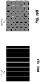
- FIG. 10A shows, for a single row of illumination array 10, a portion of a first multiline image 54a in which the left-most pixel in each group is illuminated to form a line.
- Figure 10B shows another multiline image 54b in which the next pixel in each group is illuminated.
- each group has 8 pixels, as in the examples shown herein, this sequence repeats so that there are at least 8 multiline images, one for each pixel in each group.
- each bright band of light that forms a line is a single pixel wide.
- Each multiline image projects a single line within each group, so that there is at least one bright-to-dark or dark-to-bright transition between adjacent group boundaries in a multiline image.
- each group has a number p adjacent pixels, at least p multiline images are projected onto the surface and recorded.
- more than 8 multiline images can be projected and recorded, in cyclical or other sequencing arrangement.
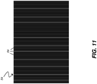
- Figure 11 shows a multiline image 54 with a line 84 within each group as projected from illumination array 10.
- Figures 12 and 13 show exemplary multiline images 54 as projected onto the surface 20 and recorded by imaging sensor array 30.
- the dashed line Q in Figure 12 indicates one row of pixels on imaging sensor array 30.
- each of the multiline images is analyzed as a set of independent rows, to locate each intensity peak in the row. This is done in two steps. Initially, a combination of smoothing filter and differentiating filter locates pixels where there is a peak signal. Then, a parabola is fit to the observed points around the identified pixel in order to locate the peak with sub-pixel accuracy. The background around the peak is also estimated to provide additional information on relative peak height. A candidate peak can be dropped from the list of peaks if it is too weak or too close to another peak. The result of the analysis is a long peak list (30,000 to 100,000 for a typical imaging sensor array) of precise locations where intensity peaks were observed.
- peaks which contains the peak location in x and y (i.e. pixel location along the row and the row number), the peak height, the peak width, and the image from which it came (multiline images 1 to p ) .
- group number For each peak, the group number from the nearest pixel in the Group Map is retrieved.
- the group number and image number are combined to calculate the line on the illuminator, 1 to 480 in a 480 line image. This gives three essential "pixel positions" for the peak: the x and y location on the imager and the x location on the illuminator, just as would be obtained from a single projected point.
- an approximate position of the point on the tooth or other surface is calculated, using the three pixel positions and calibration parameters. These approximate positions are processed, using information known from calibration, to determine an accurate location (x, y, z) on the surface. All of these locations form the point cloud, which is the final output of the combination algorithm.
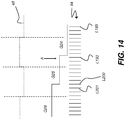
- the in-phase binary patterns 46 and out-of-phase binary patterns 48 are combined to improve the accuracy of the mapping and to compensate and identify various physical effects that might otherwise induce errors in the Group Map. For the explanation that follows:
- a portion of an out-of-phase binary pattern 48 is shown, with corresponding lines from a first captured image frame from the multiline images represented.
- a number of representative lines L185, L193, L200, and L201 are shown.
- a portion of the group mapping is also shown for groups G24, G25, and G26.
- Corresponding illuminator array pixel center positions 94 are also shown.
- Lines L193 to L200 are in group G25.
- the out-of-phase binary pattern 48 changes between groups, as described previously.
- An arrow A marks a peak observed in a phase 1 multiline image. (The phase numbers count from right to left in this example arrangement.) Errant group codes can be detected in a number of ways, including the following:
- Dark and flat images 36 and 38 are obtained as described in the sequence of Figure 3 . These images can be averaged to provide a measure of intensity that is used as a threshold to differentiate bright from dark intensities to help improve the signal mapping in pixel assignment step 44 ( Figure 3 ).
- sequence of image projections and recording can be followed in any suitable order for the methods of the present invention.
- multiline images and binary patterns can be interspersed, rather than obtained in any fixed order.
- Figures 15A and 15B compares results of processing using the method of the present invention for an uncoated tooth 90 and for a coated tooth 92, that is, a tooth coated with a powder or other material, as is needed with conventional tooth surface imaging systems that have been commercially available. As shown, results for uncoated tooth 90 compare favorably to those for coated tooth 92, without the need to prepare the tooth.
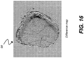
- Figure 16 shows a difference map 98 from combining the images for uncoated and coated teeth 90 and 92.
- the logic flow diagram of Figure 17 shows a sequence of image projection, detection, and processing steps used for surface contour detection and executed at least in part on a computer according to an embodiment of the present invention.
- an image capture step 40 the operator positions the imaging apparatus and captures a series of images, as described subsequently.
- the images consist of a number of group index images 102 and optional block images 104 and a number p of multiline images 54 and can be captured in any order.
- a pixel assignment step 44 executes, in which pixels on the image sensor array are assigned to a group map that corresponds to pixels on the illumination array. Images for the group mapping are from group index images 102 and block images 104, described in more detail subsequently. An additional dark image 36, with no illumination, and flat image 38 with full frame illumination are also obtained to help characterize the response of the sensor pixel array in signal processing, as described subsequently. A set of p multiline images 54 is also obtained, from which peak locations, that is, locations of highest intensity, can be detected in a location detection step 50. A mapping step 60 then forms and stores the contour image in a memory, such as in a temporary display memory that is associated with a display monitor, for example. The resulting contour image can then be displayed or further processed.
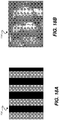
- Figure 18A shows the illumination pattern that is projected in one of the optional block images 104.
- Figure 18B shows a corresponding tooth image 114 that is obtained from projection of block image 104.
- Figure 19A shows the illumination pattern that is projected in one of the group index images 102.
- Figure 19B shows a corresponding tooth image 112 that is obtained from projection of group index image 102.
- Figure 20A shows the illumination pattern that is projected in one of the multiline images 54.
- Figure 20B shows a corresponding tooth image 116 that is obtained from projection of multiline image 54.
- Embodiments of the present invention can employ different group sizes and arrangements, including specification of which sets of groups have pixels illuminated at any one time.
- an arbitrary group size of 8 pixels is used.
- the behavior of 128 pixels, in 16 groups with 8 pixels per group, is described.
- the 16 groups form an ordered set, in the terminology used herein. It can be appreciated that changes can be made in group size or in the number of groups that are members of an ordered set, within the scope of the present invention.
- the description that follows uses these exemplary values in differentiating group index images from multiline images.
- Figures 21A and 21B compare group index and multiline images, respectively, with respect to the group arrangement for a single row of pixels 130 on illumination array 10.
- Enlarged portion E1 shows a portion of the row that is greatly enlarged to indicate groups, with representative groups G1, G2, G3, G4, and G12 labeled by way of example.
- Two lines 120 and 122 of group index image 102 are formed by illuminated pixels in groups G4 and G12, respectively. Using this pattern, each line in group index image 102 is similarly formed by energizing a portion of the pixels in every 8th group.
- For the multiline image 54 in Figure 21B by comparison, as shown in enlarged portion E2, each line 124, 126, 128, 129 ... is formed by illuminating a single pixel from each group, with representative groups G1, G2, G3, and G4 shown.
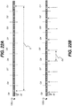
- FIG. 22A and 22B show a distinction between the group index image and the multiline image at the pixel level. Groups are numbered from right to left. Row of pixels 130a of Figure 22A shows the pattern of illuminated pixels used for projecting group index image 104 ( Figure 21A ). Here, only a pair of adjacent pixels in groups G1 and G9 are illuminated; remaining groups G2-G8 are all dark (having no illuminated pixels). In a row of pixels 130b of Figure 22B , within each of the representative groups G1-G9 shown, the pixel in the third position from the left is illuminated. Row of pixels 130b thus forms a multiline image, such as that shown in Figure 21B .
- embodiments of the present invention operate by projecting and recording a sequence of two or more group index images, as was described with respect to Figure 17 .
- each projected group index image has, in at least two of the groups in the ordered set, no illuminated pixels.
- a center-to-center distance D between illuminated pixels, spans 8 groups.
- row of pixels 130b shows the illumination pattern for multiline imaging, with a single pixel illuminated for each group. Distance D2 between illuminated pixels spans 8 pixels in this arrangement.
- each group index image in fewer than ( k-1 ) groups of the ordered set of k groups, from 2 to ( p-1 ) adjacent pixels are illuminated.
- p 8
- the group index image works well when two or three pixels near the center of the group are illuminated; the illumination of pixels nearer the borders of the group is more likely to cause some confusion or ambiguity in detection.
- Each group index image projects two lines, spaced 8 groups apart, as described with reference to the example group pattern in Figures 22A and 22B .
- Table 1 lists the illuminated pixels for each of the projected images provided using the method described with reference to Figure 17 .
- the example listing in Table 1 is for the first 128 pixels of the illumination array, using an ordered set of 16 groups with 8 pixels per group. A total of 8 group index images are projected. A total of 8 multiline images are projected. The given pattern is repeated for each subsequent 128 pixel grouping. It should be noted that images can be projected in any order.
- the decision to obtain the optional block images can be made dynamically, based on results from the group index image projection and recording. According to an embodiment of the present invention, an automated assessment of the group index images determines whether or not the block images 104 are useful.
- Correlation of pixels in a multiline image to group mapping utilizes the sequence of group index images as a guide in determining the group assignment for individual pixels.
- the group index images provide reference data for this correlation, using techniques familiar to those skilled in the contour mapping arts.
- the optional block images (for example, Figure 18A ) help further by providing information that resolves ambiguities in group mapping.
- the correlation that is obtained can be stored in any number of ways, as is well known to those skilled in the data representation arts.
- Light intensity for each image can be the same; however, there can be advantages to changing intensity for different image types. Suitable adjustment of intensity can help to reduce the impact of scattered light, for example.
- block images are projected at 50% intensity; group index images are projected at 75% intensity; and multiline images are projected at full intensity. Other intensity variations can alternately be used.
- block images 104 help to resolve possible depth ambiguities with group index images 102 and are optional. Shifting the second block image relative to the first helps to provide more accurate mapping of group assignments for light directed to the surface of the tooth or other object. Table 1.
- a computer executes a program with stored instructions that perform on image data accessed from an electronic memory.
- a computer program of an embodiment of the present invention can be utilized by a suitable, general-purpose computer system, such as a personal computer or workstation, as well as by a microprocessor or other dedicated processor or programmable logic device.
- a suitable, general-purpose computer system such as a personal computer or workstation
- a microprocessor or other dedicated processor or programmable logic device such as a microprocessor or other dedicated processor or programmable logic device.
- many other types of computer systems can be used to execute the computer program of the present invention, including networked processors.
- the computer program for performing the method of the present invention may be stored in a computer readable storage medium.
- This medium may comprise, for example; magnetic storage media such as a magnetic disk (such as a hard drive) or magnetic tape or other portable type of magnetic disk; optical storage media such as an optical disc, optical tape, or machine readable bar code; solid state electronic storage devices such as random access memory (RAM), or read only memory (ROM); or any other physical device or medium employed to store a computer program.
- the computer program for performing the method of the present invention may also be stored on computer readable storage medium that is connected to the image processor by way of the internet or other communication medium. Those skilled in the art will readily recognize that the equivalent of such a computer program product may also be constructed in hardware.
- the computer program product of the present invention may make use of various image manipulation algorithms and processes that are well known. It will be further understood that the computer program product embodiment of the present invention may embody algorithms and processes not specifically shown or described herein that are useful for implementation. Such algorithms and processes may include conventional utilities that are within the ordinary skill of the image processing arts. Additional aspects of such algorithms and systems, and hardware and/or software for producing and otherwise processing the images or co-operating with the computer program product of the present invention, are not specifically shown or described herein and may be selected from such algorithms, systems, hardware, components and elements known in the art.
- the act of "recording" images means storing image data in some type of memory circuit in order to use this image data for subsequent processing.
- the recorded image data itself may be stored more permanently or discarded once it is no longer needed for further processing.
- An "ordered set” has its conventional meaning as used in set theory, relating to a set whose elements have a non-ambiguous ordering, such as the set of natural numbers that are ordered in an ascending sequence, for example.
- memory can refer to any type of temporary or more enduring data storage workspace used for storing and operating upon image data and accessible to a computer system.
- the memory could be non-volatile, using, for example, a long-term storage medium such as magnetic or optical storage. Alternately, the memory could be of a more volatile nature, using an electronic circuit, such as random-access memory (RAM) that is used as a temporary buffer or workspace by a microprocessor or other control logic processor device.
- Display data for example, is typically stored in a temporary storage buffer that is directly associated with a display device and is periodically refreshed as needed in order to provide displayed data.
- This temporary storage buffer can also be considered to be a memory, as the term is used in the present disclosure.
- Memory is also used as the data workspace for executing and storing intermediate and final results of calculations and other processing.
- Computer-accessible memory can be volatile, non-volatile, or a hybrid combination of volatile and non-volatile types. Computer-accessible memory of various types is provided on different components throughout the system for storing, processing, transferring, and displaying data, and for other functions.
Landscapes
- Engineering & Computer Science (AREA)
- Physics & Mathematics (AREA)
- Health & Medical Sciences (AREA)
- Computer Vision & Pattern Recognition (AREA)
- General Physics & Mathematics (AREA)
- Theoretical Computer Science (AREA)
- Optics & Photonics (AREA)
- Dentistry (AREA)
- Oral & Maxillofacial Surgery (AREA)
- Epidemiology (AREA)
- Life Sciences & Earth Sciences (AREA)
- Animal Behavior & Ethology (AREA)
- General Health & Medical Sciences (AREA)
- Public Health (AREA)
- Veterinary Medicine (AREA)
- Length Measuring Devices By Optical Means (AREA)
- Image Processing (AREA)
Applications Claiming Priority (3)
| Application Number | Priority Date | Filing Date | Title |
|---|---|---|---|
| US13/293,308 US9295532B2 (en) | 2011-11-10 | 2011-11-10 | 3D intraoral measurements using optical multiline method |
| US13/525,590 US9349182B2 (en) | 2011-11-10 | 2012-06-18 | 3D intraoral measurements using optical multiline method |
| PCT/US2012/052178 WO2013070301A1 (en) | 2011-11-10 | 2012-08-24 | 3d intraoral measurements using optical multiline method |
Publications (3)
| Publication Number | Publication Date |
|---|---|
| EP2775914A1 EP2775914A1 (en) | 2014-09-17 |
| EP2775914A4 EP2775914A4 (en) | 2015-08-05 |
| EP2775914B1 true EP2775914B1 (en) | 2018-02-21 |
Family
ID=48280246
Family Applications (1)
| Application Number | Title | Priority Date | Filing Date |
|---|---|---|---|
| EP12847432.7A Not-in-force EP2775914B1 (en) | 2011-11-10 | 2012-08-24 | 3d intraoral measurements using optical multiline method |
Country Status (6)
| Country | Link |
|---|---|
| US (1) | US9349182B2 (enExample) |
| EP (1) | EP2775914B1 (enExample) |
| JP (1) | JP6072814B2 (enExample) |
| KR (1) | KR20140090620A (enExample) |
| CN (1) | CN103917160B (enExample) |
| WO (1) | WO2013070301A1 (enExample) |
Cited By (1)
| Publication number | Priority date | Publication date | Assignee | Title |
|---|---|---|---|---|
| US10223606B2 (en) | 2014-08-28 | 2019-03-05 | Carestream Dental Technology Topco Limited | 3-D intraoral measurements using optical multiline method |
Families Citing this family (27)
| Publication number | Priority date | Publication date | Assignee | Title |
|---|---|---|---|---|
| EP3268935B1 (en) * | 2015-03-09 | 2024-11-06 | Dental Imaging Technologies Corporation | Apparatus and method of texture mapping for dental 3d scanner |
| KR101671509B1 (ko) * | 2015-09-07 | 2016-11-01 | 주식회사 디오에프연구소 | 구강 스캐닝을 위한 방법 및 장치 |
| US20180296080A1 (en) | 2015-10-08 | 2018-10-18 | Carestream Dental Technology Topco Limited | Adaptive tuning of 3d acquisition speed for dental surface imaging |
| US10853957B2 (en) | 2015-10-08 | 2020-12-01 | Carestream Dental Technology Topco Limited | Real-time key view extraction for continuous 3D reconstruction |
| US11333490B2 (en) | 2015-10-30 | 2022-05-17 | Carestream Dental Technology Topco Limited | Target with features for 3-D scanner calibration |
| ES2968101T3 (es) | 2015-12-08 | 2024-05-07 | Dental Imaging Technologies Corp | Calibración de escáner 3D con dispositivo objetivo de visualización activa |
| US9858672B2 (en) * | 2016-01-15 | 2018-01-02 | Oculus Vr, Llc | Depth mapping using structured light and time of flight |
| WO2017163537A1 (ja) * | 2016-03-22 | 2017-09-28 | 三菱電機株式会社 | 距離計測装置及び距離計測方法 |
| JP6378793B2 (ja) * | 2016-05-10 | 2018-08-22 | 正樹 神原 | 歯肉診断支援装置および歯肉診断支援システム |
| CN109414161A (zh) | 2016-06-15 | 2019-03-01 | 锐珂牙科技术顶阔有限公司 | 扩展景深口内成像装置 |
| EP3978868B1 (en) * | 2016-11-21 | 2024-11-06 | Dental Imaging Technologies Corporation | 3-d intraoral surface characterization |
| US10463243B2 (en) | 2017-03-16 | 2019-11-05 | Carestream Dental Technology Topco Limited | Structured light generation for intraoral 3D camera using 1D MEMS scanning |
| US10753726B2 (en) | 2017-03-26 | 2020-08-25 | Cognex Corporation | System and method for 3D profile determination using model-based peak selection |
| US10350037B2 (en) | 2017-05-08 | 2019-07-16 | Carestream Dental Technology Topco Limited | Sawtooth wave surface detection in 3D dental reconstruction system |
| CN110996841A (zh) | 2017-06-29 | 2020-04-10 | 锐珂牙科技术顶阔有限公司 | 使用光片主动三角测量的自动口内3d扫描仪 |
| US20200197136A1 (en) | 2017-08-17 | 2020-06-25 | Trophy | Stencil for intraoral surface scanning |
| US10835352B2 (en) * | 2018-03-19 | 2020-11-17 | 3D Imaging and Simulation Corp. Americas | Intraoral scanner and computing system for capturing images and generating three-dimensional models |
| CN112912933B (zh) | 2018-05-18 | 2024-06-28 | 登塔尔图像科技公司 | 用于口腔内3d扫描的方法和口腔内成像装置 |
| US10753734B2 (en) | 2018-06-08 | 2020-08-25 | Dentsply Sirona Inc. | Device, method and system for generating dynamic projection patterns in a confocal camera |
| WO2020102658A2 (en) | 2018-11-16 | 2020-05-22 | Carestream Dental Llc | Laser projection system |
| TWI704907B (zh) | 2018-11-29 | 2020-09-21 | 財團法人金屬工業研究發展中心 | 牙體建模裝置以及牙體建模方法 |
| EP3673863A1 (en) | 2018-12-28 | 2020-07-01 | Trophy | 3d printing optimization using clinical indications |
| EP3673862A1 (en) | 2018-12-28 | 2020-07-01 | Trophy | Dental model superimposition using clinical indications |
| EP3675036A1 (en) | 2018-12-28 | 2020-07-01 | Trophy | 3d segmentation for mandible and maxilla |
| EP3673864B1 (en) | 2018-12-28 | 2025-10-22 | Nobel Biocare Services AG | Apparatus for generating a 3d model image of a patient's dentition |
| US12251278B2 (en) | 2019-03-10 | 2025-03-18 | Dental Imaging Technologies Corporation | Dental shade matching for multiple anatomical regions |
| US10631956B1 (en) | 2019-12-04 | 2020-04-28 | Oxilio Ltd | Methods and systems for making an orthodontic aligner having fixing blocks |
Family Cites Families (27)
| Publication number | Priority date | Publication date | Assignee | Title |
|---|---|---|---|---|
| US5372502A (en) * | 1988-09-02 | 1994-12-13 | Kaltenbach & Voight Gmbh & Co. | Optical probe and method for the three-dimensional surveying of teeth |
| JPH03293507A (ja) * | 1990-04-11 | 1991-12-25 | Nippondenso Co Ltd | 3次元形状測定装置 |
| US5650621A (en) * | 1993-06-21 | 1997-07-22 | Hitachi, Ltd. | Electron microscope |
| KR20000016663A (ko) | 1996-06-13 | 2000-03-25 | 에이치. 클라에스; 레이몽 드 봉 | 3차원 형상 묘사 획득용 시스템 및 방법 |
| US6754370B1 (en) | 2000-08-14 | 2004-06-22 | The Board Of Trustees Of The Leland Stanford Junior University | Real-time structured light range scanning of moving scenes |
| US7126699B1 (en) * | 2002-10-18 | 2006-10-24 | Kla-Tencor Technologies Corp. | Systems and methods for multi-dimensional metrology and/or inspection of a specimen |
| JP4289893B2 (ja) * | 2003-01-21 | 2009-07-01 | 株式会社ニッケ機械製作所 | 外観計測装置 |
| US7146036B2 (en) | 2003-02-03 | 2006-12-05 | Hewlett-Packard Development Company, L.P. | Multiframe correspondence estimation |
| WO2005010825A2 (en) | 2003-07-24 | 2005-02-03 | Cognitens Ltd. | Method and sytem for the three-dimensional surface reconstruction of an object |
| JP4480488B2 (ja) * | 2003-08-28 | 2010-06-16 | 富士通株式会社 | 計測装置、コンピュータ数値制御装置及びプログラム |
| EP1663046A4 (en) * | 2003-09-17 | 2011-10-05 | D4D Technologies Llc | HIGH SPEED THREE DIMENSIONAL SCANNING OF MULTIPLE LINES |
| WO2005082075A2 (en) | 2004-02-25 | 2005-09-09 | The University Of North Carolina At Chapel Hill | Systems and methods for imperceptibly embedding structured light patterns in projected color images |
| JP4645068B2 (ja) * | 2004-06-04 | 2011-03-09 | 旭硝子株式会社 | 表面形状の検査方法および検査装置 |
| US7916932B2 (en) * | 2005-02-16 | 2011-03-29 | In-G Co., Ltd. | Method and system of structural light-based 3D depth imaging using signal separation coding and error correction thereof |
| US7929751B2 (en) * | 2005-11-09 | 2011-04-19 | Gi, Llc | Method and apparatus for absolute-coordinate three-dimensional surface imaging |
| US7545512B2 (en) * | 2006-01-26 | 2009-06-09 | Koh Young Technology Inc. | Method for automated measurement of three-dimensional shape of circuit boards |
| CN101883520B (zh) * | 2007-08-22 | 2013-02-06 | 皇家飞利浦电子股份有限公司 | 用于表面的光学表征的方法和设备 |
| EP2051042B1 (de) | 2007-10-18 | 2010-11-03 | Nectar Imaging S.r.l. | Vorrichtung zur tomografischen Erfassung von Objekten |
| DE102007054906B4 (de) * | 2007-11-15 | 2011-07-28 | Sirona Dental Systems GmbH, 64625 | Verfahren zur optischen Vermessung der dreidimensionalen Geometrie von Objekten |
| US20090322859A1 (en) | 2008-03-20 | 2009-12-31 | Shelton Damion M | Method and System for 3D Imaging Using a Spacetime Coded Laser Projection System |
| JP5276006B2 (ja) | 2008-05-13 | 2013-08-28 | パナソニック株式会社 | 口腔内測定装置及び口腔内測定システム |
| US8411995B2 (en) | 2008-05-23 | 2013-04-02 | National Research Council Of Canada | Deconvolution-based structured light system with geometrically plausible regularization |
| CH699575A1 (de) | 2008-10-06 | 2010-04-15 | Nectar Imaging S R L | Optisches System für ein Konfokalmikroskop. |
| US20100268069A1 (en) * | 2009-04-16 | 2010-10-21 | Rongguang Liang | Dental surface imaging using polarized fringe projection |
| US8570530B2 (en) * | 2009-06-03 | 2013-10-29 | Carestream Health, Inc. | Apparatus for dental surface shape and shade imaging |
| US9046355B2 (en) * | 2009-07-29 | 2015-06-02 | Canon Kabushiki Kaisha | Measuring apparatus, measuring method, and program |
| US8908958B2 (en) | 2009-09-03 | 2014-12-09 | Ron Kimmel | Devices and methods of generating three dimensional (3D) colored models |
-
2012
- 2012-06-18 US US13/525,590 patent/US9349182B2/en active Active
- 2012-08-24 KR KR1020147012351A patent/KR20140090620A/ko not_active Ceased
- 2012-08-24 JP JP2014541042A patent/JP6072814B2/ja not_active Expired - Fee Related
- 2012-08-24 EP EP12847432.7A patent/EP2775914B1/en not_active Not-in-force
- 2012-08-24 CN CN201280055128.7A patent/CN103917160B/zh active Active
- 2012-08-24 WO PCT/US2012/052178 patent/WO2013070301A1/en not_active Ceased
Non-Patent Citations (1)
| Title |
|---|
| None * |
Cited By (1)
| Publication number | Priority date | Publication date | Assignee | Title |
|---|---|---|---|---|
| US10223606B2 (en) | 2014-08-28 | 2019-03-05 | Carestream Dental Technology Topco Limited | 3-D intraoral measurements using optical multiline method |
Also Published As
| Publication number | Publication date |
|---|---|
| JP6072814B2 (ja) | 2017-02-01 |
| CN103917160B (zh) | 2016-08-10 |
| WO2013070301A1 (en) | 2013-05-16 |
| JP2014534448A (ja) | 2014-12-18 |
| EP2775914A4 (en) | 2015-08-05 |
| US20130120533A1 (en) | 2013-05-16 |
| EP2775914A1 (en) | 2014-09-17 |
| US9349182B2 (en) | 2016-05-24 |
| CN103917160A (zh) | 2014-07-09 |
| KR20140090620A (ko) | 2014-07-17 |
| HK1195235A1 (zh) | 2014-11-07 |
Similar Documents
| Publication | Publication Date | Title |
|---|---|---|
| EP2775914B1 (en) | 3d intraoral measurements using optical multiline method | |
| US9295532B2 (en) | 3D intraoral measurements using optical multiline method | |
| US10902668B2 (en) | 3D geometric modeling and 3D video content creation | |
| KR102508717B1 (ko) | 치과 3d 스캐너를 위한 텍스쳐 매핑의 장치 및 방법 | |
| US8208719B2 (en) | 3D geometric modeling and motion capture using both single and dual imaging | |
| WO2017214735A1 (en) | Systems and methods for obtaining a structured light reconstruction of a 3d surface | |
| US10223606B2 (en) | 3-D intraoral measurements using optical multiline method | |
| US20220316868A1 (en) | 3-d intraoral surface characterization | |
| JP2008145139A (ja) | 形状計測装置 | |
| HK1195235B (en) | 3d intraoral measurements using optical multiline method |
Legal Events
| Date | Code | Title | Description |
|---|---|---|---|
| PUAI | Public reference made under article 153(3) epc to a published international application that has entered the european phase |
Free format text: ORIGINAL CODE: 0009012 |
|
| 17P | Request for examination filed |
Effective date: 20140509 |
|
| AK | Designated contracting states |
Kind code of ref document: A1 Designated state(s): AL AT BE BG CH CY CZ DE DK EE ES FI FR GB GR HR HU IE IS IT LI LT LU LV MC MK MT NL NO PL PT RO RS SE SI SK SM TR |
|
| DAX | Request for extension of the european patent (deleted) | ||
| RA4 | Supplementary search report drawn up and despatched (corrected) |
Effective date: 20150706 |
|
| RIC1 | Information provided on ipc code assigned before grant |
Ipc: G06T 7/00 20060101ALI20150630BHEP Ipc: G06T 17/00 20060101ALI20150630BHEP Ipc: A61B 5/103 20060101AFI20150630BHEP |
|
| 17Q | First examination report despatched |
Effective date: 20170221 |
|
| GRAP | Despatch of communication of intention to grant a patent |
Free format text: ORIGINAL CODE: EPIDOSNIGR1 |
|
| INTG | Intention to grant announced |
Effective date: 20170922 |
|
| GRAS | Grant fee paid |
Free format text: ORIGINAL CODE: EPIDOSNIGR3 |
|
| RAP1 | Party data changed (applicant data changed or rights of an application transferred) |
Owner name: CARESTREAM DENTAL TECHNOLOGY TOPCO LIMITED |
|
| GRAA | (expected) grant |
Free format text: ORIGINAL CODE: 0009210 |
|
| AK | Designated contracting states |
Kind code of ref document: B1 Designated state(s): AL AT BE BG CH CY CZ DE DK EE ES FI FR GB GR HR HU IE IS IT LI LT LU LV MC MK MT NL NO PL PT RO RS SE SI SK SM TR |
|
| REG | Reference to a national code |
Ref country code: GB Ref legal event code: FG4D |
|
| REG | Reference to a national code |
Ref country code: CH Ref legal event code: EP |
|
| REG | Reference to a national code |
Ref country code: AT Ref legal event code: REF Ref document number: 970809 Country of ref document: AT Kind code of ref document: T Effective date: 20180315 |
|
| REG | Reference to a national code |
Ref country code: IE Ref legal event code: FG4D |
|
| REG | Reference to a national code |
Ref country code: DE Ref legal event code: R096 Ref document number: 602012043187 Country of ref document: DE |
|
| REG | Reference to a national code |
Ref country code: NL Ref legal event code: MP Effective date: 20180221 |
|
| REG | Reference to a national code |
Ref country code: LT Ref legal event code: MG4D |
|
| REG | Reference to a national code |
Ref country code: AT Ref legal event code: MK05 Ref document number: 970809 Country of ref document: AT Kind code of ref document: T Effective date: 20180221 |
|
| REG | Reference to a national code |
Ref country code: FR Ref legal event code: PLFP Year of fee payment: 7 |
|
| PG25 | Lapsed in a contracting state [announced via postgrant information from national office to epo] |
Ref country code: HR Free format text: LAPSE BECAUSE OF FAILURE TO SUBMIT A TRANSLATION OF THE DESCRIPTION OR TO PAY THE FEE WITHIN THE PRESCRIBED TIME-LIMIT Effective date: 20180221 Ref country code: CY Free format text: LAPSE BECAUSE OF FAILURE TO SUBMIT A TRANSLATION OF THE DESCRIPTION OR TO PAY THE FEE WITHIN THE PRESCRIBED TIME-LIMIT Effective date: 20180221 Ref country code: FI Free format text: LAPSE BECAUSE OF FAILURE TO SUBMIT A TRANSLATION OF THE DESCRIPTION OR TO PAY THE FEE WITHIN THE PRESCRIBED TIME-LIMIT Effective date: 20180221 Ref country code: NO Free format text: LAPSE BECAUSE OF FAILURE TO SUBMIT A TRANSLATION OF THE DESCRIPTION OR TO PAY THE FEE WITHIN THE PRESCRIBED TIME-LIMIT Effective date: 20180521 Ref country code: ES Free format text: LAPSE BECAUSE OF FAILURE TO SUBMIT A TRANSLATION OF THE DESCRIPTION OR TO PAY THE FEE WITHIN THE PRESCRIBED TIME-LIMIT Effective date: 20180221 Ref country code: NL Free format text: LAPSE BECAUSE OF FAILURE TO SUBMIT A TRANSLATION OF THE DESCRIPTION OR TO PAY THE FEE WITHIN THE PRESCRIBED TIME-LIMIT Effective date: 20180221 Ref country code: LT Free format text: LAPSE BECAUSE OF FAILURE TO SUBMIT A TRANSLATION OF THE DESCRIPTION OR TO PAY THE FEE WITHIN THE PRESCRIBED TIME-LIMIT Effective date: 20180221 |
|
| PG25 | Lapsed in a contracting state [announced via postgrant information from national office to epo] |
Ref country code: SE Free format text: LAPSE BECAUSE OF FAILURE TO SUBMIT A TRANSLATION OF THE DESCRIPTION OR TO PAY THE FEE WITHIN THE PRESCRIBED TIME-LIMIT Effective date: 20180221 Ref country code: LV Free format text: LAPSE BECAUSE OF FAILURE TO SUBMIT A TRANSLATION OF THE DESCRIPTION OR TO PAY THE FEE WITHIN THE PRESCRIBED TIME-LIMIT Effective date: 20180221 Ref country code: AT Free format text: LAPSE BECAUSE OF FAILURE TO SUBMIT A TRANSLATION OF THE DESCRIPTION OR TO PAY THE FEE WITHIN THE PRESCRIBED TIME-LIMIT Effective date: 20180221 Ref country code: RS Free format text: LAPSE BECAUSE OF FAILURE TO SUBMIT A TRANSLATION OF THE DESCRIPTION OR TO PAY THE FEE WITHIN THE PRESCRIBED TIME-LIMIT Effective date: 20180221 Ref country code: BG Free format text: LAPSE BECAUSE OF FAILURE TO SUBMIT A TRANSLATION OF THE DESCRIPTION OR TO PAY THE FEE WITHIN THE PRESCRIBED TIME-LIMIT Effective date: 20180521 Ref country code: GR Free format text: LAPSE BECAUSE OF FAILURE TO SUBMIT A TRANSLATION OF THE DESCRIPTION OR TO PAY THE FEE WITHIN THE PRESCRIBED TIME-LIMIT Effective date: 20180522 |
|
| PG25 | Lapsed in a contracting state [announced via postgrant information from national office to epo] |
Ref country code: RO Free format text: LAPSE BECAUSE OF FAILURE TO SUBMIT A TRANSLATION OF THE DESCRIPTION OR TO PAY THE FEE WITHIN THE PRESCRIBED TIME-LIMIT Effective date: 20180221 Ref country code: IT Free format text: LAPSE BECAUSE OF FAILURE TO SUBMIT A TRANSLATION OF THE DESCRIPTION OR TO PAY THE FEE WITHIN THE PRESCRIBED TIME-LIMIT Effective date: 20180221 Ref country code: PL Free format text: LAPSE BECAUSE OF FAILURE TO SUBMIT A TRANSLATION OF THE DESCRIPTION OR TO PAY THE FEE WITHIN THE PRESCRIBED TIME-LIMIT Effective date: 20180221 Ref country code: EE Free format text: LAPSE BECAUSE OF FAILURE TO SUBMIT A TRANSLATION OF THE DESCRIPTION OR TO PAY THE FEE WITHIN THE PRESCRIBED TIME-LIMIT Effective date: 20180221 Ref country code: AL Free format text: LAPSE BECAUSE OF FAILURE TO SUBMIT A TRANSLATION OF THE DESCRIPTION OR TO PAY THE FEE WITHIN THE PRESCRIBED TIME-LIMIT Effective date: 20180221 |
|
| REG | Reference to a national code |
Ref country code: DE Ref legal event code: R097 Ref document number: 602012043187 Country of ref document: DE |
|
| PG25 | Lapsed in a contracting state [announced via postgrant information from national office to epo] |
Ref country code: SM Free format text: LAPSE BECAUSE OF FAILURE TO SUBMIT A TRANSLATION OF THE DESCRIPTION OR TO PAY THE FEE WITHIN THE PRESCRIBED TIME-LIMIT Effective date: 20180221 Ref country code: DK Free format text: LAPSE BECAUSE OF FAILURE TO SUBMIT A TRANSLATION OF THE DESCRIPTION OR TO PAY THE FEE WITHIN THE PRESCRIBED TIME-LIMIT Effective date: 20180221 Ref country code: SK Free format text: LAPSE BECAUSE OF FAILURE TO SUBMIT A TRANSLATION OF THE DESCRIPTION OR TO PAY THE FEE WITHIN THE PRESCRIBED TIME-LIMIT Effective date: 20180221 Ref country code: CZ Free format text: LAPSE BECAUSE OF FAILURE TO SUBMIT A TRANSLATION OF THE DESCRIPTION OR TO PAY THE FEE WITHIN THE PRESCRIBED TIME-LIMIT Effective date: 20180221 |
|
| PLBE | No opposition filed within time limit |
Free format text: ORIGINAL CODE: 0009261 |
|
| STAA | Information on the status of an ep patent application or granted ep patent |
Free format text: STATUS: NO OPPOSITION FILED WITHIN TIME LIMIT |
|
| 26N | No opposition filed |
Effective date: 20181122 |
|
| PG25 | Lapsed in a contracting state [announced via postgrant information from national office to epo] |
Ref country code: SI Free format text: LAPSE BECAUSE OF FAILURE TO SUBMIT A TRANSLATION OF THE DESCRIPTION OR TO PAY THE FEE WITHIN THE PRESCRIBED TIME-LIMIT Effective date: 20180221 |
|
| PG25 | Lapsed in a contracting state [announced via postgrant information from national office to epo] |
Ref country code: MC Free format text: LAPSE BECAUSE OF FAILURE TO SUBMIT A TRANSLATION OF THE DESCRIPTION OR TO PAY THE FEE WITHIN THE PRESCRIBED TIME-LIMIT Effective date: 20180221 |
|
| REG | Reference to a national code |
Ref country code: CH Ref legal event code: PL |
|
| PG25 | Lapsed in a contracting state [announced via postgrant information from national office to epo] |
Ref country code: LU Free format text: LAPSE BECAUSE OF NON-PAYMENT OF DUE FEES Effective date: 20180824 Ref country code: LI Free format text: LAPSE BECAUSE OF NON-PAYMENT OF DUE FEES Effective date: 20180831 Ref country code: CH Free format text: LAPSE BECAUSE OF NON-PAYMENT OF DUE FEES Effective date: 20180831 |
|
| REG | Reference to a national code |
Ref country code: BE Ref legal event code: MM Effective date: 20180831 |
|
| PG25 | Lapsed in a contracting state [announced via postgrant information from national office to epo] |
Ref country code: BE Free format text: LAPSE BECAUSE OF NON-PAYMENT OF DUE FEES Effective date: 20180831 |
|
| PGFP | Annual fee paid to national office [announced via postgrant information from national office to epo] |
Ref country code: FR Payment date: 20190717 Year of fee payment: 8 Ref country code: DE Payment date: 20190715 Year of fee payment: 8 |
|
| PGFP | Annual fee paid to national office [announced via postgrant information from national office to epo] |
Ref country code: GB Payment date: 20190728 Year of fee payment: 8 |
|
| PG25 | Lapsed in a contracting state [announced via postgrant information from national office to epo] |
Ref country code: MT Free format text: LAPSE BECAUSE OF NON-PAYMENT OF DUE FEES Effective date: 20180824 |
|
| PG25 | Lapsed in a contracting state [announced via postgrant information from national office to epo] |
Ref country code: TR Free format text: LAPSE BECAUSE OF FAILURE TO SUBMIT A TRANSLATION OF THE DESCRIPTION OR TO PAY THE FEE WITHIN THE PRESCRIBED TIME-LIMIT Effective date: 20180221 |
|
| PG25 | Lapsed in a contracting state [announced via postgrant information from national office to epo] |
Ref country code: HU Free format text: LAPSE BECAUSE OF FAILURE TO SUBMIT A TRANSLATION OF THE DESCRIPTION OR TO PAY THE FEE WITHIN THE PRESCRIBED TIME-LIMIT; INVALID AB INITIO Effective date: 20120824 Ref country code: PT Free format text: LAPSE BECAUSE OF FAILURE TO SUBMIT A TRANSLATION OF THE DESCRIPTION OR TO PAY THE FEE WITHIN THE PRESCRIBED TIME-LIMIT Effective date: 20180221 |
|
| PG25 | Lapsed in a contracting state [announced via postgrant information from national office to epo] |
Ref country code: IE Free format text: LAPSE BECAUSE OF NON-PAYMENT OF DUE FEES Effective date: 20180824 Ref country code: MK Free format text: LAPSE BECAUSE OF NON-PAYMENT OF DUE FEES Effective date: 20180221 |
|
| PG25 | Lapsed in a contracting state [announced via postgrant information from national office to epo] |
Ref country code: IS Free format text: LAPSE BECAUSE OF FAILURE TO SUBMIT A TRANSLATION OF THE DESCRIPTION OR TO PAY THE FEE WITHIN THE PRESCRIBED TIME-LIMIT Effective date: 20180621 |
|
| REG | Reference to a national code |
Ref country code: DE Ref legal event code: R119 Ref document number: 602012043187 Country of ref document: DE |
|
| GBPC | Gb: european patent ceased through non-payment of renewal fee |
Effective date: 20200824 |
|
| PG25 | Lapsed in a contracting state [announced via postgrant information from national office to epo] |
Ref country code: FR Free format text: LAPSE BECAUSE OF NON-PAYMENT OF DUE FEES Effective date: 20200831 Ref country code: DE Free format text: LAPSE BECAUSE OF NON-PAYMENT OF DUE FEES Effective date: 20210302 |
|
| PG25 | Lapsed in a contracting state [announced via postgrant information from national office to epo] |
Ref country code: GB Free format text: LAPSE BECAUSE OF NON-PAYMENT OF DUE FEES Effective date: 20200824 |