EP2775714A1 - Video encoding device, video decoding device, video encoding method, video decoding method, and program - Google Patents
Video encoding device, video decoding device, video encoding method, video decoding method, and program Download PDFInfo
- Publication number
- EP2775714A1 EP2775714A1 EP12845094.7A EP12845094A EP2775714A1 EP 2775714 A1 EP2775714 A1 EP 2775714A1 EP 12845094 A EP12845094 A EP 12845094A EP 2775714 A1 EP2775714 A1 EP 2775714A1
- Authority
- EP
- European Patent Office
- Prior art keywords
- luminance signal
- sampling position
- sampled
- sampled luminance
- sampling
- Prior art date
- Legal status (The legal status is an assumption and is not a legal conclusion. Google has not performed a legal analysis and makes no representation as to the accuracy of the status listed.)
- Withdrawn
Links
- 238000000034 method Methods 0.000 title claims description 54
- 238000005070 sampling Methods 0.000 claims abstract description 212
- 230000000750 progressive effect Effects 0.000 claims description 39
- 238000010586 diagram Methods 0.000 description 17
- 230000015556 catabolic process Effects 0.000 description 5
- 238000006731 degradation reaction Methods 0.000 description 5
- 238000012856 packing Methods 0.000 description 4
- NRNCYVBFPDDJNE-UHFFFAOYSA-N pemoline Chemical compound O1C(N)=NC(=O)C1C1=CC=CC=C1 NRNCYVBFPDDJNE-UHFFFAOYSA-N 0.000 description 4
- 241000023320 Luma <angiosperm> Species 0.000 description 3
- 230000010365 information processing Effects 0.000 description 3
- OSWPMRLSEDHDFF-UHFFFAOYSA-N methyl salicylate Chemical group COC(=O)C1=CC=CC=C1O OSWPMRLSEDHDFF-UHFFFAOYSA-N 0.000 description 3
- 230000003068 static effect Effects 0.000 description 3
- 208000037170 Delayed Emergence from Anesthesia Diseases 0.000 description 2
- 230000006870 function Effects 0.000 description 2
- NAWXUBYGYWOOIX-SFHVURJKSA-N (2s)-2-[[4-[2-(2,4-diaminoquinazolin-6-yl)ethyl]benzoyl]amino]-4-methylidenepentanedioic acid Chemical compound C1=CC2=NC(N)=NC(N)=C2C=C1CCC1=CC=C(C(=O)N[C@@H](CC(=C)C(O)=O)C(O)=O)C=C1 NAWXUBYGYWOOIX-SFHVURJKSA-N 0.000 description 1
- 239000004288 Sodium dehydroacetate Substances 0.000 description 1
- 238000004364 calculation method Methods 0.000 description 1
- 238000006243 chemical reaction Methods 0.000 description 1
- 238000004590 computer program Methods 0.000 description 1
- 230000000694 effects Effects 0.000 description 1
- 238000013139 quantization Methods 0.000 description 1
- 230000011664 signaling Effects 0.000 description 1
Images


Classifications
-
- H—ELECTRICITY
- H04—ELECTRIC COMMUNICATION TECHNIQUE
- H04N—PICTORIAL COMMUNICATION, e.g. TELEVISION
- H04N19/00—Methods or arrangements for coding, decoding, compressing or decompressing digital video signals
- H04N19/10—Methods or arrangements for coding, decoding, compressing or decompressing digital video signals using adaptive coding
- H04N19/102—Methods or arrangements for coding, decoding, compressing or decompressing digital video signals using adaptive coding characterised by the element, parameter or selection affected or controlled by the adaptive coding
- H04N19/132—Sampling, masking or truncation of coding units, e.g. adaptive resampling, frame skipping, frame interpolation or high-frequency transform coefficient masking
-
- H—ELECTRICITY
- H04—ELECTRIC COMMUNICATION TECHNIQUE
- H04N—PICTORIAL COMMUNICATION, e.g. TELEVISION
- H04N19/00—Methods or arrangements for coding, decoding, compressing or decompressing digital video signals
- H04N19/10—Methods or arrangements for coding, decoding, compressing or decompressing digital video signals using adaptive coding
- H04N19/102—Methods or arrangements for coding, decoding, compressing or decompressing digital video signals using adaptive coding characterised by the element, parameter or selection affected or controlled by the adaptive coding
- H04N19/103—Selection of coding mode or of prediction mode
- H04N19/105—Selection of the reference unit for prediction within a chosen coding or prediction mode, e.g. adaptive choice of position and number of pixels used for prediction
-
- H—ELECTRICITY
- H04—ELECTRIC COMMUNICATION TECHNIQUE
- H04N—PICTORIAL COMMUNICATION, e.g. TELEVISION
- H04N19/00—Methods or arrangements for coding, decoding, compressing or decompressing digital video signals
- H04N19/10—Methods or arrangements for coding, decoding, compressing or decompressing digital video signals using adaptive coding
- H04N19/134—Methods or arrangements for coding, decoding, compressing or decompressing digital video signals using adaptive coding characterised by the element, parameter or criterion affecting or controlling the adaptive coding
- H04N19/157—Assigned coding mode, i.e. the coding mode being predefined or preselected to be further used for selection of another element or parameter
- H04N19/16—Assigned coding mode, i.e. the coding mode being predefined or preselected to be further used for selection of another element or parameter for a given display mode, e.g. for interlaced or progressive display mode
-
- H—ELECTRICITY
- H04—ELECTRIC COMMUNICATION TECHNIQUE
- H04N—PICTORIAL COMMUNICATION, e.g. TELEVISION
- H04N19/00—Methods or arrangements for coding, decoding, compressing or decompressing digital video signals
- H04N19/10—Methods or arrangements for coding, decoding, compressing or decompressing digital video signals using adaptive coding
- H04N19/169—Methods or arrangements for coding, decoding, compressing or decompressing digital video signals using adaptive coding characterised by the coding unit, i.e. the structural portion or semantic portion of the video signal being the object or the subject of the adaptive coding
- H04N19/182—Methods or arrangements for coding, decoding, compressing or decompressing digital video signals using adaptive coding characterised by the coding unit, i.e. the structural portion or semantic portion of the video signal being the object or the subject of the adaptive coding the unit being a pixel
-
- H—ELECTRICITY
- H04—ELECTRIC COMMUNICATION TECHNIQUE
- H04N—PICTORIAL COMMUNICATION, e.g. TELEVISION
- H04N19/00—Methods or arrangements for coding, decoding, compressing or decompressing digital video signals
- H04N19/10—Methods or arrangements for coding, decoding, compressing or decompressing digital video signals using adaptive coding
- H04N19/169—Methods or arrangements for coding, decoding, compressing or decompressing digital video signals using adaptive coding characterised by the coding unit, i.e. the structural portion or semantic portion of the video signal being the object or the subject of the adaptive coding
- H04N19/186—Methods or arrangements for coding, decoding, compressing or decompressing digital video signals using adaptive coding characterised by the coding unit, i.e. the structural portion or semantic portion of the video signal being the object or the subject of the adaptive coding the unit being a colour or a chrominance component
-
- H—ELECTRICITY
- H04—ELECTRIC COMMUNICATION TECHNIQUE
- H04N—PICTORIAL COMMUNICATION, e.g. TELEVISION
- H04N19/00—Methods or arrangements for coding, decoding, compressing or decompressing digital video signals
- H04N19/50—Methods or arrangements for coding, decoding, compressing or decompressing digital video signals using predictive coding
- H04N19/59—Methods or arrangements for coding, decoding, compressing or decompressing digital video signals using predictive coding involving spatial sub-sampling or interpolation, e.g. alteration of picture size or resolution
-
- H—ELECTRICITY
- H04—ELECTRIC COMMUNICATION TECHNIQUE
- H04N—PICTORIAL COMMUNICATION, e.g. TELEVISION
- H04N19/00—Methods or arrangements for coding, decoding, compressing or decompressing digital video signals
- H04N19/60—Methods or arrangements for coding, decoding, compressing or decompressing digital video signals using transform coding
- H04N19/61—Methods or arrangements for coding, decoding, compressing or decompressing digital video signals using transform coding in combination with predictive coding
-
- H—ELECTRICITY
- H04—ELECTRIC COMMUNICATION TECHNIQUE
- H04N—PICTORIAL COMMUNICATION, e.g. TELEVISION
- H04N19/00—Methods or arrangements for coding, decoding, compressing or decompressing digital video signals
- H04N19/70—Methods or arrangements for coding, decoding, compressing or decompressing digital video signals characterised by syntax aspects related to video coding, e.g. related to compression standards
Definitions
- the present invention relates to a video encoding device and a video decoding device for predicting color difference signal from a down-sampled luminance signal.
- Non Patent Literature (NPL) 1 discloses a new color difference signal prediction (hereinafter, referred to as intra_chromaFromLuma prediction) technique that utilizes cross-correlation between a luminance signal (luma signal) and color difference signal (chroma signal) of the same coding unit.
- NPL 2 describes specific operation steps of an intra_chromaFromLuma prediction in Section 8.3.3.1.8 Specification of Intra_FromLuma prediction mode. The overview thereof will be described below.
- Fig 2 is a block diagram illustrating a video coding device using a prediction intra_chromaFromLuma prediction described in NPL 1.
- the video encoding device illustrated in Fig. 2 encodes a Largest Coding Unit (LCU) constituting a frame in the raster scan order, and encodes a coding unit (CU) constituting the LCU in a Z scan order ( Fig. 3 ).
- the video encoding apparatus further divides the CU into Prediction Units (PUs) ( Fig. 4 ).
- the block size of the prediction is a block size of the PU. (For example, when the CU size is 32 ⁇ 32 and the PU size is 2N ⁇ 2N, nS is 16.)
- a residual signal obtained by subtracting an input signal (input block signal) from a prediction signal (prediction block signal) generated from the predictor 101 is transformed into a residual frequency conversion quantization index (residual level) through a frequency transformer 102 and a quantizer 103.
- An entropy encoder 104 entropy-encodes the residual level to output a bitstream.
- the residual level is transformed into a reconstructed residual signal (reconstructed residual block signal) through the inverse quantizer/inverse frequency transformer 105, and a signal obtained by adding the prediction signal to the reconstructed residual signal is stored in a buffer 106 as a reconstructed signal (reconstructed block signal).
- a down-sampler 107A generates a down-sampled luminance signal of the reconstructed luminance signal based on the processing of step 1.
- the predictor 101 generates a color difference prediction signal based on the processing of steps 2, 3 and 4 using the down-sampled luminance signal supplied from the down-sampler 107A and the reconstructed color difference signal supplied from the buffer 106.
- NPL 1 longitudinally shifts a sampling position in a down-sampled luminance signal (down-sampled luminance sampling position) by 1/2 pixels. Therefore, a down-sampled luminance sampling position under interlaced scan of 4 : 2 : 0 is longitudinally shifted.
- a sampling position in a down-sampled luminance signal corresponding to sampling position in a color difference signal is shifted downward in the top field by 1/4 pixels ( Fig. 9(b) ).
- a sampling position in the down-sampled luminance signal corresponding to a sampling position in the color difference signal is shifted in the bottom field by 1/4 pixels ( Fig. 9(b) ).
- the color difference prediction signal is generated from the down-sampled luminance signal in which a sampling position is longitudinally shifted.
- the sampling position in the color difference prediction signal is also longitudinally shifted, there is a problem that the image quality of the color difference signal is lowered.
- the present invention is directed to suitably maintain the sampling position in the color difference prediction signal generated from the down-sampled luminance signal, thereby preventing degradation in image quality of the color difference signals.
- a video encoding device comprises: a luminance signal down-sample means configured to down-sample a luminance signal; and a prediction means configured to linearly predict a color difference signal from a down-sampled luminance signal, wherein the luminance signal down-sample means shifts a sampling position in the down-sampled luminance signal depending on a scan to be processed.
- a video decoding device comprises: a luminance signal down-sample means configured to down-sample a luminance signal; and a prediction means configured to linearly predict a color difference signal from a down-sampled luminance signal, wherein the luminance signal down-sample means shifts a sampling position in the down-sampled luminance signal depending on a scan to be processed.
- a video encoding method is a video encoding method comprising: down-sampling a luminance signal and linearly predicting a color difference signal from a down-sampled luminance signal, the method further comprising: shifting a sampling position in the down-sampled luminance signal depending on a scan to be processed.
- a video decoding method is a video decoding method comprising: down-sampling a luminance signal and linearly predicting to a color difference signal from a down-sampled luminance signal, the method further comprising: shifting a sampling position in the down-sampled luminance signal depending on a scan to be processed.
- a video encoding program is a video encoding program for causing a computer to execute a process of down-sampling a luminance signal and a process of linearly predicting a color difference signal from a down-sampled luminance signal, and the video encoding program causes a computer to execute a process of shifting a sampling position in the down-sampled luminance signal depending on a scan to be processed.
- a video decoding program is a video decoding program for causing a computer to execute a process of down-sampling a luminance signal and a process of linearly predicting a color difference signal from a down-sampled luminance signal, and the video decoding program causes a computer to execute a process of shifting a sampling position in the down-sampled luminance signal depending on a scan to be processed.
- the sampling position in the color difference prediction signal generated from the down-sampled luminance signal is kept suitable, and it is possible to prevent degradation in image quality of the color difference signals.
- the present invention generates a down-sampled luminance signal of a sampling position corresponding to a sampling position in a color difference signal with respect to a sampling position in a luminance signal to be processed. If a target to be processed is scanned by a 4 : 2 : 0 progressive scanning, a down-sampled luminance signal with a sampling position vertically shifted by 1/2 pixels is generated. If a target to be processed is a top field of a 4 : 2 : 0 interlaced scanning, a down-sampled luminance signal with a sampling position vertically shifted by 1/4 pixels is generated.
- a target to be processed is a bottom field of the 4 : 2 : 0 interlaced scanning
- a down-sampled luminance signal with a sampling position vertically shifted by 3/4 is generated.
- a down-sampled luminance signal of a sampling position corresponding to a scan to be processed is generated.
- the sampling position in the color difference prediction signal generated from the down-sampled luminance signal is kept suitable, and it is possible to prevent degradation in image quality of the color difference signals.
- a video encoding device of a first exemplary embodiment illustrated in Fig. 10 includes a predictor 101, a frequency transformer 102, a quantizer 103, an entropy encoder 104, an inverse quantizer/inverse frequency transformer 105, a buffer 106, and a down-sampler with sampling position shifter 107.
- the down-sampler with sampling position shifter 107 is the feature part of the present invention. Since multiplexing the scan according to a bitstream by the entropy encoder 104 is not the feature of the present invention, the entropy encoder 104 is also equivalent to the entropy encoder 104 illustrated in Fig. 2 .
- the operation of the down-sampler with sampling position shifter 107 being the feature of the present invention will be described.
- the down-sampler with sampling position shifter 107 generates a down-sampled luminance signal having a shift amount which corresponds to the sampling position in the color difference signal corresponding to the sampling position in the luminance signal in the scan to be processed.
- the scanning to be processed may be determined by the video encoding device according to a dynamic/static determination of a target to be processed (applying a progressive scanning to a static area, applying an interlaced scanning to a dynamic region wherein an odd line is assigned to a top field and an even line is assigned to a bottom field) or an encoding determination (the better encoding result of the progressive scanning and the interlaced scanning). It is assumed that the auxiliary information on the scanning to be processed is multiplexed to a bitstream by the entropy encoder 104. Moreover, if the scanning to be processed is the interlaced scanning, it is assumed that auxiliary information indicating the top field or the bottom field is also multiplexed to the bitstream by the entropy encoder 104.
- p Y ⁇ ⁇ x y recSamplesL 2 ⁇ x , 2 ⁇ y + recSamplesL ⁇ 2 ⁇ x , 2 ⁇ y + 1 > > 1
- a down-sampled luminance signal is generated by a filter of [1/2, 1/2] so that a sampling position in the down-sampled luminance signal is vertically shifted by 1/2 ( Fig. 12 (a) ).
- p Y ⁇ ⁇ x y 3 * recSamplesL 2 ⁇ x , 2 ⁇ y + recSamplesL ⁇ 2 ⁇ x , 2 ⁇ y + 1 > > 2
- a down-sampled luminance signal is generated by a filter of [3/4, 1/4] so that the sampling position in the down-sampled luminance signal is vertically shifted by 1/4 ( Fig. 12 (b) ).
- p Y ⁇ ⁇ x y recSamplesL 2 ⁇ x , 2 ⁇ y + 3 * recSamplesL ⁇ 2 ⁇ x , 2 ⁇ y + 1 > > 2
- a down-sampled luminance signal is generated by a filter of [1/4, 3/4] so that the sampling position in the down-sampled luminance signal is vertically shifted by 3/4 ( Fig. 12 (c) ).
- a down-sampled luminance signal having a shift amount with respect to a sampling position in a luminance signal is generated according to a scan to be processed.
- a video decoding device includes an entropy decoder 201, an inverse quantizer/inverse frequency transformer 202, a predictor 203, a buffer 204, and a down-sampler with sampling position shifter 205.
- the entropy decoder 201 entropy-decodes a bitstream, and entropy-decodes a scan to be processed (frame, block or slice) and a residual level. In addition, if the scanning of the target to be processed is an interlaced scanning, auxiliary information indicating the top field or the bottom field is also entropy-decoded.
- the inverse quantizer/inverse frequency transformer 202 inverse-quantizes a supplied residual level, and performs inverse frequency transform of the inverse-quantized residual level to output a reconstructed residual signal.
- a prediction signal supplied from the predictor 203 is added to reconstructed residual signal so that the result is stored in the buffer 204 as a reconstructed signal.
- the down-sampler with sampling position shifter 205 generates a down-sampled luminance signal of a sampling position which corresponds to sampling position of color difference signal corresponding to a sampling position in a luminance signal of a scan based on the scan to be processed, which is supplied from the entropy decoder 201.
- a down-sampled luminance signal is generated by a filter of [1/2, 1/2] so that a sampling position in the down-sampled luminance signal is vertically shifted by 1/2 ( Fig. 12 (a) ).
- the down-sampled luminance signal is generated by a filter of [3/4, 1/4] so that a sampling position in the down-sampled luminance signal is vertically shifted by 1/4 ( Fig. 12 (b) ).
- the down-sampled luminance signal is generated by a filter of [1/4, 3/4] so that the sampling position in the down-sampled luminance signal is vertically shifted by 3/4 ( Fig. 12 (c) ).
- the predictor 203 uses the down-sampled luminance signal supplied from the down-sampler with sampling position shifter 205 and the reconstructed color difference signal supplied from the buffer 204 to generate the color difference prediction signal on the basis of the processing in the above-described steps 2, 3 and 4.
- a down-sampled luminance signal having a shift amount according to a sampling position in color difference signal corresponding to a sampling position in a luminance signal of a scan to be processed is generated based on the scan to be processed, which is supplied from the entropy decoder 201.
- the video decoding device of the present invention it is possible to suitably maintain a sampling position in a color difference prediction signal generated from the down-sampled luminance signal, thereby preventing the degradation in image quality of the color difference signal.
- Formula (6) means that the shifted luminance signal is down-sampled by 1/2 by vertically shifting a luminance signal by 1/2 pixels using a two-dimensional filter with coefficients of [[1/8, 2/8, 1/8] and [1/8, 2/8, 1/8]] ( Fig. 15 (a) ).
- the down-sampler with sampling position shifter may generate a down-sampled luminance signal by a two-dimensional filter with coefficients of [[3/16, 6/16, 3/16] and [1/16, 2/16, 1/16]] so that a sampling position in a down-sampled luminance signal is vertically 1/4 shifted in step 1 ( Fig. 15(b) ). That is, if the target to be processed is a top field of an interlaced scanning, Formula (7) below may be used.
- the down-sampler with sampling position shifter may generate the down-sampled luminance signal by a two-dimensional filter with coefficients of [[1/16, 2/16, 1/16] and [3/16, 6/16, 3/16]] so that a sampling position in a down-sampled luminance signal is vertically 3/4 shifted in step 1 ( Fig. 15(b) ). That is, if the target to be processed is a bottom field of an interlaced scanning, Formula (8) below may be used.
- a sample-position shift down-sampler may use a two-dimensional filter of Figs. 16(a) to 16(c) .
- Formula (9) may be used.
- p Y ⁇ ⁇ x y recSamplesL ⁇ 2 ⁇ x - 1 , 2 ⁇ y + recSamplesL ⁇ 2 ⁇ x + 1 , 2 ⁇ y + 3 * recSamplesL ⁇ 2 ⁇ x - 1 , 2 ⁇ y + 1 + recSamplesL ⁇ 2 ⁇ x + 1 , 2 ⁇ y + 1 > > 2
- Formula (10) may be used.
- p Y ⁇ ⁇ x y ( 3 * recSamplesL ⁇ 2 ⁇ x - 1 , 2 ⁇ y + 3 * recSamplesL ⁇ 2 ⁇ x + 1 , 2 ⁇ y + recSamplesL ⁇ 2 ⁇ x - 1 , 2 ⁇ y + 1 + recSamplesL ⁇ 2 ⁇ x + 1 , 2 ⁇ y + 1 ) > > 3
- Formula (11) may be used.
- p Y ⁇ ⁇ x y recSamplesL ⁇ 2 ⁇ x - 1 , 2 ⁇ y + recSamplesL ⁇ 2 ⁇ x + 1 , 2 ⁇ y + 3 * recSamplesL ⁇ 2 ⁇ x - 1 , 2 ⁇ y + 1 + 3 * recSamplesL ⁇ 2 ⁇ x + 1 , 2 ⁇ y + 1 > > 3
- p Y ⁇ ⁇ x y recSamplesL ⁇ 2 ⁇ x - 1 , - 1 + 2 * recSamplesL ⁇ 2 ⁇ x , - 1 + recSamplesL ⁇ 2 ⁇ x + 1 , - 1 > > 2
- a row down-sampled luminance signal of the block boundary may be calculated by Formula (12) above, and other down-sampled luminance signal may be calculated by Formulas of the present invention.
- p Y ⁇ ⁇ x y recSamplesL 2 ⁇ x , 2 ⁇ y + recSamplesL ⁇ 2 ⁇ x , 2 ⁇ y + 1 > > 1
- row and column luminance signals of the block boundary may be calculated by Formulas (12) and (13) above, respectively, and other down-sampled luminance signals may be calculated by Formula of the present invention.
- Video encoding based on NPL 3 may signal to a video decoding side that the target to be processed is the progressive scanning by setting field_pic_flag described in 7.3.3 Slice header syntax as 0 and setting mb_field_decoding_flag described in 7.3.4 Slice data syntax described as 0.
- the video encoding may also signal to the video decoding side that the target to be processed is the top field of the interlaced scanning by setting field_pic_flag and bottom_field_flag described in 7.3.3 Slice header syntax as 1 and 0, respectively, and by setting mb_field_decoding_flag described in 7.3.4 Slice data syntax as 1.
- the video encoding may also signal to the video decoding side that the target to be processed is the top field of the interlaced scanning by setting field_pic_flag described in 7.3.3 Slice header syntax as 1, by setting bottom_field_flag as 1, and by setting mb_field_decoding_flag described in 7.3.4 Slice data syntax as 1.
- video coding based on NPL 2 does not include the field_pic_flag syntax, the bottom_field_flag syntax, and the mb_field_decoding_flag syntax of NPL 3.
- it may newly define a syntax that explicitly indicates a sampling position relationship between the luminance signal and the color difference signal to be processed (that is, the shift amount of the sampling position in the down-sampled luminance signal).
- a syntax luma_down_sampling_shift_idc indicating the shift amount of the sampling position in the down-sampled luminance signal may be defined as follows.
- luma_down_sampling_shift_idc indicates the shift amount of the sampling position in the down-sampled luminance signal.
- luma_down_sampling_shift_idc has a value in the range of 0 to 3. If the luma_down_sampling_shift_idc is not present, its value is regarded as 0.
- a shift amount of 1/4 pixels in the top field of the interlaced scanning is -1/4 pixel shift
- a shift amount of 3/4 pixels in the bottom field of the interlaced scanning is 1/4 pixel shift.
- luma_down_sampling_shift_idc indicates the shift amount of the sampling position in the down-sampled luminance signal.
- luma_down_sampling_idc has a value in the range of 0 to 3. If the luma_down_sampling_shift_idc is not present, its value is regarded as 0.
- the luma_down_sampling_shift_idc syntax may be signaled in a signaling/sequence parameter set, a picture parameter set, a slice header, and the like.
- video encoding based on NPL 2 does not include the field_pic_flag syntax, the bottom_field_flag syntax, and the mb_field_decoding_flag syntax of NPL 3. Therefore, when encoding an input video of an interlaced scanning signal of 4 : 2 : 0, it may be considered to invalidate the intra_chromaFromLuma prediction.
- To invalidate the intra_chromaFromLuma prediction is to set chroma_pred_from_luma_enabled_flag described in 7.3.2.1 Sequence parameter set RBSP syntax as 0 or to set the chroma_pred_from_luma_enabled_flag and 1, and to set intra_chroma_pred_mode described in 7.3.7 Prediction unit syntax to non-zero (set IntraPredMode to a value other than 35, that is, Intra_FromLuma prediction mode).
- the input video of the interlaced scanning signal of 4 : 2 : 0 may be detected by an external setting, or may be detected by the dynamic/static determination.
- Fig. 17(a) illustrates a frame packing where a top field and a bottom field are disposed at a lower half and an upper half of one frame, respectively.
- the present invention in the frame packing case of Fig. 17(a) , in the encoding/decoding of the upper half of the frame, the present invention generates a down-sampled luminance signal so that a sampling position in the down-sampled luminance signal is vertically shifted by 1/4.
- the present invention In the encoding/decoding of the lower half of the frame, the present invention generates the down-sampled luminance signal so that the sampling position in the down-sampled luminance signal is vertically shifted by 3/4.
- the present invention In the frame packing case of Fig. 17(b) (when a top field and a bottom field are disposed in the top half and the bottom half of one frame, respectively), the present invention generates the down-sampled luminance signal so that the sampling position in the down-sampled luminance signal is vertically shifted by 3/4 in the encoding/decoding of the upper half of the frame. In the encoding/decoding of the lower half of the frame, the present invention generates a down-sampled luminance signal so that a sampling position in the down-sampled luminance signal is vertically shifted by 1/4.
- the information processing system illustrated in Fig. 18 includes a processor 1001, a program memory 1002, a storage medium 1003 for storing video data, and the storage medium 1004 for storing a bitstream.
- the storage medium 1003 and the storage medium 1004 may be different storage mediums, or may be storage areas on the same storage medium.
- a magnetic storage medium such as a hard disk may be used as the storage medium.
- the program memory 1002 stores a program for carrying out the function of each block illustrated in each of Figs. 10 and 13 , respectively.
- the processor 1001 performs processing according to the program stored in the program memory 1002 to carry out the functions of the video encoding device or the video decoding device illustrated in Figs. 10 and 13 , respectively.
- a video encoding device comprising a luminance signal down-sample means configured to at least vertically down-sample a luminance signal by 1/2, and a prediction means configured to linearly predict (perform linear prediction) a color difference signal from a down-sampled luminance signal, wherein the luminance signal down-sample means shifts a sampling position in the down-sampled luminance signal depending on a scan to be processed, the luminance signal down-sample means shifts by 1/2 a sampling position in a down-sampled luminance signal under progressive scan using a filter with a coefficient of [1/2, 1/2], shifts by 1/4 a sampling position in a down-sampled luminance signal included in a top field of an interlaced scanning using a filter with a coefficient of [1/4, 3/4], and shifts by 3/4 a sampling position in the down-sampled luminance signal included in a bottom field of the interlaced scanning using a filter with a coefficient of [3/4, 1/4].
- a video encoding device comprising a luminance signal down-sample means configured to at least vertically down-sample a luminance signal by 1/2, and a prediction means configured to linearly predict a color difference signal from a down-sampled luminance signal, wherein the luminance signal down-sample means shifts by 1/2 a sampling position in a down-sampled luminance signal under progressive scan, shifts by 1/4 a sampling position in a down-sampled luminance signal included in a top field of an interlaced scanning, and shifts by 3/4 a sampling position in the down-sampled luminance signal included in a bottom field of the interlaced scanning, and the luminance signal down-sample means shifts by 1/2 the sampling position in the down-sampled luminance signal in the progressive scanning using a two-dimensional filter with coefficients of [[1/8, 2/8, 1/8] and [1/8, 2/8, 1/8]], shifts by 1/4 the sampling position in a down-sampled luminance signal included in a top field of the
- a video encoding device comprising a luminance signal down-sample means configured to at least vertically down-sample a luminance signal by 1/2, and a prediction means configured to linearly predict a color difference signal from a down-sampled luminance signal, wherein the luminance signal down-sample means shifts a sampling position in the down-sampled luminance signal depending on a scan to be processed, and the luminance signal down-sample means shifts by 1/2 a sampling position in a down-sampled luminance signal under progressive scan using a two-dimensional filter with coefficients of [[1/4, 0, 1/8] and [1/8, 2/8, 1/8]], shifts by 1/4 a sampling position in a down-sampled luminance signal included in a top field of an interlaced scanning using a filter with coefficients of [[3/8 0, 3/8] and [1/8, 0, 1/8]], and shifts by 3/4 a sampling position in the down-sampled luminance signal included in a bottom field of the interlaced scanning using
- a video decoding device comprising a luminance signal down-sample means configured to at least vertically down-sample a luminance signal by 1/2, and a prediction means configured to linearly predict a color difference signal from a down-sampled luminance signal, wherein the luminance signal down-sample means shifts a sampling position in the down-sampled luminance signal depending on a scan to be processed, the luminance signal down-sample means shifts by 1/2 a sampling position in a down-sampled luminance signal under progressive scan using a filter with a coefficient of [1/2, 1/2], shifts by 1/4 a sampling position in a down-sampled luminance signal included in a top field of an interlaced scanning using a filter with a coefficient of [1/4, 3/4], and shifts by 3/4 a sampling position in the down-sampled luminance signal included in a bottom field of the interlaced scanning using a filter with a coefficient of [3/4, 1/4].
- a video decoding device comprising a luminance signal down-sample means configured to at least vertically down-sample a luminance signal by 1/2, and a prediction means configured to linearly predict a color difference signal from a down-sampled luminance signal, wherein the luminance signal down-sample means shifts by 1/2 a sampling position in the down-sampled luminance signal under progressive scan, shifts by 1/4 the sampling position in the down-sampled luminance signal included in a top field of an interlaced scanning, and shifts by 3/4 the sampling position in the down-sampled luminance signal included in a bottom field of the interlaced scanning, and the luminance signal down-sample means shifts by 1/2 the sampling position in the down-sampled luminance signal in the progressive scanning using a two-dimensional filter with coefficients of [[1/8, 2/8, 1/8] and [1/8, 2/8, 1/8]], shifts by 1/4 the sampling position in the down-sampled luminance signal included in the top field of the interlaced scanning using a
- a video decoding device comprising a luminance signal down-sample means configured to at least vertically down-sample a luminance signal by 1/2, and a prediction means configured to linearly predict a color difference signal from a down-sampled luminance signal, wherein the luminance signal down-sample means shifts a sampling position in the down-sampled luminance signal depending on a scan to be processed, and the luminance signal down-sample means shifts by 1/2 the sampling position in the down-sampled luminance signal under progressive scan using a two-dimensional filter with coefficients of [[1/4, 0, 1/8] and [1/8, 2/8, 1/8]], shifts by 1/4 the sampling position in the down-sampled luminance signal included in a top field of an interlaced scanning using a filter with coefficients of [[3/8 0, 3/8] and [1/8, 0, 1/8]], and shifts by 3/4 the sampling position in the down-sampled luminance signal included in a bottom field of the interlaced scanning using a filter with coefficients of
- a video encoding method comprising at least vertically down-sampling a luminance signal by 1/2, linearly predicting a color difference signal from a down-sampled luminance signal, and shifting a sampling position in the down-sampled luminance signal depending on a scan to be processed, the method further comprising: shifting by 1/2 the sampling position in the down-sampled luminance signal under progressive scan using a filter with a coefficient of [1/2, 1/2], shifting by 1/4 the sampling position in the down-sampled luminance signal included in a top field of an interlaced scanning using a filter with a coefficient of [1/4, 3/4], and shifting by 3/4 the sampling position in the down-sampled luminance signal included in a bottom field of the interlaced scanning using a filter with a coefficient of [3/4, 1/4].
- a video encoding method comprising at least vertically down-sampling a luminance signal by 1/2, linearly predicting a color difference signal from a down-sampled luminance signal, and shifting a sampling position in the down-sampled luminance signal depending on a scan to be processed, the method further comprising: shifting by 1/2 a sampling position in a down-sampled luminance signal in progressive scan using a two-dimensional filter with coefficients of [[1/8, 2/8, 1/8] and [1/8, 2/8, 1/8]]; shifting by 1/4 a sampling position in a down-sampled luminance signal included in a top field of an interlaced scanning using a filter with coefficients of [[3/16, 6/16, 3/16] and [1/16, 2/16, 1/16]]; and shifting by 3/4 a sampling position in the down-sampled luminance signal included in a bottom field of the interlaced scanning using a filter with coefficients of [[1/16, 2/16, 1/16] and [3/16, 6/16, 3/16]].
- a video encoding method comprising at least vertically down-sampling a luminance signal by 1/2, linearly predicting a color difference signal from a down-sampled luminance signal, and shifting a sampling position in the down-sampled luminance signal depending on a scan to be processed, the method further comprising: shifting by 1/2 a sampling position in a down-sampled luminance signal under progressive scan using a two-dimensional filter with coefficients of [[1/4, 0, 1/8] and [1/8, 2/8, 1/8]]; shifting by 1/4 a sampling position in a down-sampled luminance signal included in a top field of an interlaced scanning using a filter with coefficients of [[3/8 0, 3/8] and [1/8, 0, 1/8]]; and shifting by 3/4 a sampling position in the down-sampled luminance signal included in a bottom field of the interlaced scanning using a filter with coefficients of [[1/8, 0, 1/8] and [3/8 0, 3/8]].
- a video decoding method comprising at least vertically down-sampling a luminance signal by 1/2, linearly predicting a color difference signal from a down-sampled luminance signal, and shifting a sampling position in the down-sampled luminance signal depending on a scan to be processed, the method further comprising: shifting by 1/2 a sampling position in a down-sampled luminance signal under progressive scan using a filter with a coefficient of [1/2, 1/2]; shifting by 1/4 a sampling position in a down-sampled luminance signal included in a top field of an interlaced scanning using a filter with a coefficient of [1/4, 3/4]; and shifting by 3/4 a sampling position in the down-sampled luminance signal included in a bottom field of the interlaced scanning using a filter with a coefficient of [3/4, 1/4].
- a video decoding method comprising at least vertically down-sampling a luminance signal by 1/2, linearly predicting a color difference signal from a down-sampled luminance signal, and shifting a sampling position in the down-sampled luminance signal depending on a scan to be processed, the method further comprising: shifting by 1/2 a sampling position in a down-sampled luminance signal under progressive scan using a two-dimensional filter with coefficients of [[1/8, 2/8, 1/8] and [1/8, 2/8, 1/8]]]; shifting by 1/4 a sampling position in a down-sampled luminance signal included in a top field of an interlaced scanning using a filter with coefficients of [[3/16, 6/16, 3/16] and [1/16, 2/16, 1/16]]; and shifting by 3/4 a sampling position in the down-sampled luminance signal included in a bottom field of the interlaced scanning using a filter with coefficients of [[1/16, 2/16, 1/16] and [3/16, 6/16, 3/16]].
- a video decoding method comprising at least vertically down-sampling a luminance signal by 1/2, linearly predicting a color difference signal from a down-sampled luminance signal, and shifting a sampling position in the down-sampled luminance signal depending on a scan to be processed, the method further comprising: shifting by 1/2 a sampling position in a down-sampled luminance signal under progressive scan using a two-dimensional filter with coefficients of [[1/4, 0, 1/8] and [1/8, 2/8, 1/8]]; shifting by 1/4 a sampling position in a down-sampled luminance signal included in a top field of an interlaced scanning using a filter with coefficients of [[3/8 0, 3/8] and [1/8, 0, 1/8]]; and shifting by 3/4 a sampling position in the down-sampled luminance signal in a bottom field of the interlaced scanning using a filter with coefficients of [[1/8, 0, 1/8] and [3/8 0, 3/8]].
- a video encoding program for causing a computer to execute processes of at least vertically down-sampling a luminance signal by 1/2, linearly predicting a color difference signal from a down-sampled luminance signal, and shifting a sampling position in the down-sampled luminance signal depending on a scan to be processed, the video encoding program for causing a computer to execute processes of shifting by 1/2 a sampling position in a down-sampled luminance signal under progressive scan; shifting by 1/4 a sampling position in a down-sampled luminance signal included in a top field of an interlaced scanning; and shifting by 3/4 a sampling position in the down-sampled luminance signal included in a bottom field of the interlaced scanning.
- the video encoding program of Supplementary note 13 for causing a computer to execute processes of shifting by 1/2 a sampling position in the down-sampled luminance signal under progressive scan using a filter with a coefficient of [1/2, 1/2]; shifting by 1/4 a sampling position in the down-sampled luminance signal included in a top field of an interlaced scanning using a filter with a coefficient of [1/4, 3/4]; and shifting by 3/4 a sampling position in the down-sampled luminance signal included in a bottom field in the interlaced scanning using a filter with a coefficient of [3/4, 1/4].
- the video encoding program of Supplementary note 13 for causing a computer to execute processes of shifting by 1/2 a sampling position in a down-sampled luminance signal under progressive scan using a two-dimensional filter with coefficients of [[1/8, 2/8, 1/8] and [1/8, 2/8, 1/8]]; shifting by 1/4 a sampling position in the down-sampled luminance signal included in a top field of an interlaced scanning using a filter with coefficients of [[3/16, 6/16, 3/16] and [1/16, 2/16, 1/16]]; and shifting by 3/4 a sampling position in the down-sampled luminance signal included in a bottom field under interlaced scan using a filter with coefficients of [[1/16, 2/16, 1/16] and [3/16, 6/16, 3/16]].
- the video encoding program of Supplementary note 13 for causing a computer to execute processes of shifting by 1/2 a sampling position in a down-sampled luminance signal under progressive scan using a two-dimensional filter with coefficients of [[1/4, 0, 1/8] and [1/8, 2/8, 1/8]]; shifting by 1/4 a sampling position in a down-sampled luminance signal included in a top field of an interlaced scanning using a filter with coefficients of [[3/8 0, 3/8] and [1/8, 0, 1/8]]; and shifting by 3/4 a sampling position in the down-sampled luminance signal included in a bottom field of the interlaced scanning using a filter with coefficients of [[1/8, 0, 1/8] and [3/8 0, 3/8]].
- a video decoding program for causing a computer to execute processes of vertically down-sampling a luminance signal by 1/2, linearly predicting a color difference signal from a down-sampled luminance signal, and shift a sampling position in the down-sampled luminance signal depending on a scan to be processed, the video decoding program for causing a computer to execute processes of shifting by 1/2 a sampling position in the down-sampled luminance signal under progressive scan; shifting by 1/4 a sampling position in the down-sampled luminance signal included in a top field of an interlaced scanning; and shifting by 3/4 a sampling position in the down-sampled luminance signal included in a bottom field of the interlaced scanning.
- the video decoding program of Supplementary note 17 for causing a computer to execute processes of shifting by 1/2 a sampling position in the down-sampled luminance signal under progressive scan using a filter with a coefficient of [1/2, 1/2]; shifting by 1/4 a sampling position in the down-sampled luminance signal included in a top field of an interlaced scanning using a filter with a coefficient of [1/4, 3/4]; and shifting by 3/4 a sampling position in the down-sampled luminance signal included in a bottom field of the interlaced scanning using a filter with a coefficient of [3/4, 1/4].
- the video decoding program of Supplementary note 17 for causing a computer to execute processes of shifting by 1/2 a sampling position in the down-sampled luminance signal under progressive scan using a two-dimensional filter with coefficients of [[1/8, 2/8, 1/8] and [1/8, 2/8, 1/8]]; shifting by 1/4 a sampling position in the down-sampled luminance signal included in a top field of an interlaced scanning using a filter with coefficients of [[3/16, 6/16, 3/16] and [1/16, 2/16, 1/16]]; and shifting by 3/4 a sampling position in the down-sampled luminance signal included in a bottom field of the interlaced scanning using a filter with coefficients of [[1/16, 2/16, 1/16] and [3/16, 6/16, 3/16]].
- the video decoding program of Supplementary note 17 for causing a computer to execute processes of shifting by 1/2 a sampling position in the down-sampled luminance signal under progressive scanning using a two-dimensional filter with coefficients of [[1/4, 0, 1/8] and [1/8, 2/8, 1/8]]; shifting by 1/4 a sampling position in the down-sampled luminance signal included in a top field of an interlaced scanning using a filter with coefficients of [[3/8 0, 3/8] and [1/8, 0, 1/8]]; and shifting by 3/4 a sampling position in the down-sampled luminance signal included in a bottom field of the interlaced scanning using a filter with coefficients of [[1/8, 0, 1/8] and [3/8 0, 3/8]].
- the present invention is preferably applicable to a video encoding device and a video decoding device for predicting color difference signals from a down-sampled luminance signal.
Abstract
Description
- The present invention relates to a video encoding device and a video decoding device for predicting color difference signal from a down-sampled luminance signal.
- Non Patent Literature (NPL) 1 discloses a new color difference signal prediction (hereinafter, referred to as intra_chromaFromLuma prediction) technique that utilizes cross-correlation between a luminance signal (luma signal) and color difference signal (chroma signal) of the same coding unit.
NPL 2 describes specific operation steps of an intra_chromaFromLuma prediction in Section 8.3.3.1.8 Specification of Intra_FromLuma prediction mode. The overview thereof will be described below. - (Step 1) a down-sampled luminance signal pY' [x, y] (x = -1 .. nS - 1, y = -1 .. nS - 1) obtained by vertically 1/2 down-sampling a reconstructed luminance signal predSamples[x, y] every horizontal 2 pixels is calculated using Formula (1) below.

where nS is a width of a color difference signal (color difference block signal) (that is, a width of a reconstructed luminance signal (chrominance block signal) required for processing is 2 + 2 * nS (Fig. 1 )). - (Step 2) Based on pY'[x, y] (x, y = -1 .. nS - 1) and the reconstructed color difference signals p[x, y] (x = -1, y = 0, ... nS - 1 and x = 0, ... nS - 1, y = -1), the sum L of down-sampled luminance signals of the block boundary, the sum C of color difference signals of the block boundary, the sum S of squares of the down-sampled luminance signals of the block boundary, and the sum X of multiplication values between the down-sampled luminance signals of the block boundary and the color difference signals of the block boundary are calculated.
- (Step 3) Linear prediction coefficients a and b for linearly predicting color difference signal (y) of the block boundary are calculated from a down-sampled luminance signal (pY') of the block boundary on the basis of L, C, S, and X. Further, linear prediction coefficients a and b are calculated in order to minimize the sum of squares Σ(y - a*pY' - b)2 of a prediction error of linear prediction.
- (Step 4) Based on the calculated a and b, the color difference prediction signal predSamples[x, y] (x, y = -1 .. nS - 1) in the block is calculated from a down-sampled luminance signal pY'[x, y] in the block by Formula (2) below.

-
Fig 2 is a block diagram illustrating a video coding device using a prediction intra_chromaFromLuma prediction described inNPL 1. The video encoding device illustrated inFig. 2 encodes a Largest Coding Unit (LCU) constituting a frame in the raster scan order, and encodes a coding unit (CU) constituting the LCU in a Z scan order (Fig. 3 ). In addition, the video encoding apparatus further divides the CU into Prediction Units (PUs) (Fig. 4 ). Thus, the block size of the prediction is a block size of the PU. (For example, when the CU size is 32 × 32 and the PU size is 2N × 2N, nS is 16.) - In the video encoding apparatus illustrated in
Fig. 2 , a residual signal (residual block signal) obtained by subtracting an input signal (input block signal) from a prediction signal (prediction block signal) generated from thepredictor 101 is transformed into a residual frequency conversion quantization index (residual level) through afrequency transformer 102 and aquantizer 103. Anentropy encoder 104 entropy-encodes the residual level to output a bitstream. For prediction of the input signal afterward, the residual level is transformed into a reconstructed residual signal (reconstructed residual block signal) through the inverse quantizer/inverse frequency transformer 105, and a signal obtained by adding the prediction signal to the reconstructed residual signal is stored in abuffer 106 as a reconstructed signal (reconstructed block signal). A down-sampler 107A generates a down-sampled luminance signal of the reconstructed luminance signal based on the processing ofstep 1. Thepredictor 101 generates a color difference prediction signal based on the processing ofsteps sampler 107A and the reconstructed color difference signal supplied from thebuffer 106. -
- NPL 1: Jianle Chen, Vadim Seregin, Woo-Jin Han, Jungsun Kim, and Byeongmoon Jeon, "CE6.a.4: Chroma intra prediction by reconstructed luma samples", JCTVC-E266, Joint Collaborative Team on Video Coding (JCT-VC) of ITU-T SG16 WP3 and ISO/IEC JTC1/SC29/WG11 5th Meeting: Geneva, 16-23 March, 2011
- NPL 2: Benjamin Bross, Woo-Jin Han, Jens-Rainer Ohm, Gary J. Sullivan, and Thomas Wiegand, "WD4:
- NPL 3: "ISO/IEC 14496-10
- NPL 4: Minezawa, K. Sugimoto, S. Sekiguchi (Mitsubishi), "An improvement to chroma intra prediction from luma", JCTVC-F173, Joint Collaborative Team on Video Coding (JCT-VC) of ITU-T SG16 WP3 and ISO/IEC JTC1/SC29/WG11 6th Meeting: Torino, IT, 14-22 July, 2011
- NPL 5: Jianle Chen, "BoG report on simplification of intra_chromaFromLuma mode prediction", JCTVC-F760, Joint Collaborative Team on Video Coding (JCT-VC) of ITU-T SG16 WP3 and ISO/IEC JTC1/SC29/WG11 6th Meeting: Torino, IT, 14-22 July, 2011
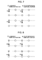
- In a progressive scanning 4 : 2 : 0 and an interlaced scanning of 4 : 2 : 0 (
Fig. 5(a) and 5(b) ), the sampling positions in the color difference signal corresponding to the sampling positions in the luminance signal are different (Fig. 6 ,Fig. 7, and Fig. 8 ). (Note that the sampling positions in a color difference signal corresponding to the sampling positions under interlaced scan of 4 : 2 : 0 have been also described inFig. 6-2 ofNPL 1.) - The technique described in
NPL 1 longitudinally shifts a sampling position in a down-sampled luminance signal (down-sampled luminance sampling position) by 1/2 pixels. Therefore, a down-sampled luminance sampling position under interlaced scan of 4 : 2 : 0 is longitudinally shifted. - Specifically, in the interlaced scanning, a sampling position in a down-sampled luminance signal corresponding to sampling position in a color difference signal is shifted downward in the top field by 1/4 pixels (
Fig. 9(b) ). In addition, a sampling position in the down-sampled luminance signal corresponding to a sampling position in the color difference signal is shifted in the bottom field by 1/4 pixels (Fig. 9(b) ). - If the sampling position in the down-sampled luminance signal is longitudinally shifted, the color difference prediction signal is generated from the down-sampled luminance signal in which a sampling position is longitudinally shifted. As a result, since the sampling position in the color difference prediction signal is also longitudinally shifted, there is a problem that the image quality of the color difference signal is lowered.
- The present invention is directed to suitably maintain the sampling position in the color difference prediction signal generated from the down-sampled luminance signal, thereby preventing degradation in image quality of the color difference signals.
- A video encoding device according to the present invention comprises: a luminance signal down-sample means configured to down-sample a luminance signal; and a prediction means configured to linearly predict a color difference signal from a down-sampled luminance signal, wherein the luminance signal down-sample means shifts a sampling position in the down-sampled luminance signal depending on a scan to be processed.
- A video decoding device according to the present invention comprises: a luminance signal down-sample means configured to down-sample a luminance signal; and a prediction means configured to linearly predict a color difference signal from a down-sampled luminance signal, wherein the luminance signal down-sample means shifts a sampling position in the down-sampled luminance signal depending on a scan to be processed.
- A video encoding method according to the present invention is a video encoding method comprising: down-sampling a luminance signal and linearly predicting a color difference signal from a down-sampled luminance signal, the method further comprising: shifting a sampling position in the down-sampled luminance signal depending on a scan to be processed.
- A video decoding method according to the present invention is a video decoding method comprising: down-sampling a luminance signal and linearly predicting to a color difference signal from a down-sampled luminance signal, the method further comprising: shifting a sampling position in the down-sampled luminance signal depending on a scan to be processed.
- A video encoding program according to the present invention is a video encoding program for causing a computer to execute a process of down-sampling a luminance signal and a process of linearly predicting a color difference signal from a down-sampled luminance signal, and the video encoding program causes a computer to execute a process of shifting a sampling position in the down-sampled luminance signal depending on a scan to be processed.
- A video decoding program according to the present invention is a video decoding program for causing a computer to execute a process of down-sampling a luminance signal and a process of linearly predicting a color difference signal from a down-sampled luminance signal, and the video decoding program causes a computer to execute a process of shifting a sampling position in the down-sampled luminance signal depending on a scan to be processed.
- According to the present invention, the sampling position in the color difference prediction signal generated from the down-sampled luminance signal is kept suitable, and it is possible to prevent degradation in image quality of the color difference signals.
-
-
Fig. 1 It depicts an explanatory diagram illustrating the relationship between a luminance block (Y) and color difference blocks (V and U). -
Fig. 2 It depicts a configuration diagram illustrating a general video encoding device. -
Fig. 3 It depicts an explanatory diagram illustrating the relationship between, a frame, an LCU, and a CU. -
Fig. 4 It depicts an explanatory diagram illustrating a shape of a PU (in the case of intra-CU). -
Fig. 5 . It depicts an explanatory diagram illustrating an example of a progressive scanning and an interlaced scanning. -
Fig. 6 It depicts an explanatory diagram illustrating sampling positions in a color difference signal and a luminance signal under progressive scan. -
Fig. 7 It depicts an explanatory diagram illustrating the sampling positions of the luminance signal and the color difference signal in the top field of the interlaced scanning. -
Fig. 8 It depicts an explanatory diagram illustrating the sampling positions of the luminance signal and the color difference signal in the bottom field of the interlaced scanning. -
Fig. 9 It depicts an explanatory diagram illustrating a luminance down-sampling position (number within a circle in the luminance sampling position is a filter coefficient) according to the related art. -
Fig. 10 It depicts a block diagram illustrating a configuration example of a video encoding device according to a first exemplary embodiment. -
Fig. 11 It depicts a flowchart illustrating an operation example of a down-sampler with sampling position shifter. -
Fig. 12 It depicts an explanatory diagram illustrating a luminance down-sampling position (number within a circle in the luminance sampling position is a filter coefficient) according to the present technology. -
Fig. 13 It depicts a block diagram illustrating a configuration example of a video encoding device according to a second exemplary embodiment. -
Fig. 14 It depicts a flowchart illustrating an operation example of a down-sampler with sampling position shifter. -
Fig. 15 It depicts an explanatory diagram illustrating a first example of a luminance down-sampling position according to other embodiments of the present invention. -
Fig. 16 It depicts an explanatory diagram illustrating a second example of the luminance down-sampling position according to other embodiments of the present invention. -
Fig. 17 It depicts an explanatory diagram illustrating an example of a frame packing of an interlaced signal. -
Fig. 18 It depicts a block diagram illustrating a configuration example of an information processing apparatus according to the present invention. - The present invention generates a down-sampled luminance signal of a sampling position corresponding to a sampling position in a color difference signal with respect to a sampling position in a luminance signal to be processed. If a target to be processed is scanned by a 4 : 2 : 0 progressive scanning, a down-sampled luminance signal with a sampling position vertically shifted by 1/2 pixels is generated. If a target to be processed is a top field of a 4 : 2 : 0 interlaced scanning, a down-sampled luminance signal with a sampling position vertically shifted by 1/4 pixels is generated. If a target to be processed is a bottom field of the 4 : 2 : 0 interlaced scanning, a down-sampled luminance signal with a sampling position vertically shifted by 3/4 is generated. Thus, a down-sampled luminance signal of a sampling position corresponding to a scan to be processed is generated. As a result, the sampling position in the color difference prediction signal generated from the down-sampled luminance signal is kept suitable, and it is possible to prevent degradation in image quality of the color difference signals.
- A video encoding device of a first exemplary embodiment illustrated in
Fig. 10 includes apredictor 101, afrequency transformer 102, aquantizer 103, anentropy encoder 104, an inverse quantizer/inverse frequency transformer 105, abuffer 106, and a down-sampler withsampling position shifter 107. - As is apparent from comparison with a video encoding device illustrated in
Fig. 2 , the down-sampler withsampling position shifter 107 is the feature part of the present invention. Since multiplexing the scan according to a bitstream by theentropy encoder 104 is not the feature of the present invention, theentropy encoder 104 is also equivalent to theentropy encoder 104 illustrated inFig. 2 . Hereinafter, the operation of the down-sampler withsampling position shifter 107 being the feature of the present invention will be described. - The down-sampler with
sampling position shifter 107 generates a down-sampled luminance signal having a shift amount which corresponds to the sampling position in the color difference signal corresponding to the sampling position in the luminance signal in the scan to be processed. - The scanning to be processed may be determined by the video encoding device according to a dynamic/static determination of a target to be processed (applying a progressive scanning to a static area, applying an interlaced scanning to a dynamic region wherein an odd line is assigned to a top field and an even line is assigned to a bottom field) or an encoding determination (the better encoding result of the progressive scanning and the interlaced scanning). It is assumed that the auxiliary information on the scanning to be processed is multiplexed to a bitstream by the
entropy encoder 104. Moreover, if the scanning to be processed is the interlaced scanning, it is assumed that auxiliary information indicating the top field or the bottom field is also multiplexed to the bitstream by theentropy encoder 104. - Hereinafter, the operation of the down-sampler with
sampling position shifter 107 being the feature of the present invention will be described with reference to the flowchart ofFig. 11 . - If a target to be processed is the progressive scanning (step S101), a down-sampler with
sampling position shifter 107, in step S102, calculates a down-sampled luminance signal pY'[x, y] (x = -1 .. nS - 1, y = -1 .. nS - 1) in the above-describedstep 1 by Formula (3) below.
- That is, a down-sampled luminance signal is generated by a filter of [1/2, 1/2] so that a sampling position in the down-sampled luminance signal is vertically shifted by 1/2 (
Fig. 12 (a) ). - When the target to be processed is the top field of interlaced scanning (step S103), the down-sampler with
sampling position shifter 107, in step S104, calculates the down-sampled luminance signal pY'[x, y] (x = -1 .. nS - 1, y = -1 .. nS - 1) according to the above-describedstep 1 by Formula (4) below.
- That is, a down-sampled luminance signal is generated by a filter of [3/4, 1/4] so that the sampling position in the down-sampled luminance signal is vertically shifted by 1/4 (
Fig. 12 (b) ). - When the target to be processed is the bottom field of interlaced scanning (step S105), the down-sampler with
sampling position shifter 107, in step S106, calculates the down-sampled luminance signal pY'[x, y] (x = -1 .. nS - 1, y = -1 .. nS - 1) in the above-describedstep 1 by Formula (5) below.
- That is, a down-sampled luminance signal is generated by a filter of [1/4, 3/4] so that the sampling position in the down-sampled luminance signal is vertically shifted by 3/4 (
Fig. 12 (c) ). - As above, the description about the operation of the down-sampler with
sampling position shifter 107 is finished. - By the operation of the down-sampler with
sampling position shifter 107 as described above, a down-sampled luminance signal having a shift amount with respect to a sampling position in a luminance signal is generated according to a scan to be processed. As a result, in the video encoding device of the present invention, it is possible to suitably maintain a sampling position in a color difference prediction signal generated from the down-sampled luminance signal, thereby preventing the degradation in image quality of the color difference signal. - A video decoding device according to a second exemplary embodiment of the present invention illustrated in
Fig. 13 includes anentropy decoder 201, an inverse quantizer/inverse frequency transformer 202, apredictor 203, abuffer 204, and a down-sampler withsampling position shifter 205. - The
entropy decoder 201 entropy-decodes a bitstream, and entropy-decodes a scan to be processed (frame, block or slice) and a residual level. In addition, if the scanning of the target to be processed is an interlaced scanning, auxiliary information indicating the top field or the bottom field is also entropy-decoded. - The inverse quantizer/
inverse frequency transformer 202 inverse-quantizes a supplied residual level, and performs inverse frequency transform of the inverse-quantized residual level to output a reconstructed residual signal. A prediction signal supplied from thepredictor 203 is added to reconstructed residual signal so that the result is stored in thebuffer 204 as a reconstructed signal. - The operation of the down-sampler with
sampling position shifter 205 being the feature of the present invention will now be described with reference to the flowchart ofFig. 14 . - The down-sampler with
sampling position shifter 205 generates a down-sampled luminance signal of a sampling position which corresponds to sampling position of color difference signal corresponding to a sampling position in a luminance signal of a scan based on the scan to be processed, which is supplied from theentropy decoder 201. - Specifically, when the target to be processed is the progressive scanning (step S201), the down-sampler with
sampling position shifter 205, in step S202, the down-sampled luminance signal pY'[x, y] (x = -1 .. nS - 1, y = - 1 .. nS - 1) in the above-describedstep 1 by Formula (3). - That is, a down-sampled luminance signal is generated by a filter of [1/2, 1/2] so that a sampling position in the down-sampled luminance signal is vertically shifted by 1/2 (
Fig. 12 (a) ). - When the target to be processed is the top field of interlaced scanning (step S203), the down-sampler with
sampling position shifter 205, in step S204, calculates the down-sampled luminance signal pY'[x, y] (x = -1 .. nS - 1, y = -1 .. nS - 1) according to the above-describedstep 1 by Formula (4) below. - That is, the down-sampled luminance signal is generated by a filter of [3/4, 1/4] so that a sampling position in the down-sampled luminance signal is vertically shifted by 1/4 (
Fig. 12 (b) ). - When the scan to be processed is the bottom field of interlaced scanning (step S205), the down-sampler with
sampling position shifter 205, in step S206, calculates the down-sampled luminance signal pY'[x, y] (x = -1 .. nS - 1, y = -1 .. nS - 1) in the above-describedstep 1 by Formula (5) below. - That is, the down-sampled luminance signal is generated by a filter of [1/4, 3/4] so that the sampling position in the down-sampled luminance signal is vertically shifted by 3/4 (
Fig. 12 (c) ). - Using the down-sampled luminance signal supplied from the down-sampler with
sampling position shifter 205 and the reconstructed color difference signal supplied from thebuffer 204, thepredictor 203 generates the color difference prediction signal on the basis of the processing in the above-describedsteps - As above, the description about the operation of the video decoding device of the second exemplary embodiment of the present invention is finished.
- By the operation of the down-sampler with
sampling position shifter 205 as described above, a down-sampled luminance signal having a shift amount according to a sampling position in color difference signal corresponding to a sampling position in a luminance signal of a scan to be processed is generated based on the scan to be processed, which is supplied from theentropy decoder 201. As a result, in the video decoding device of the present invention, it is possible to suitably maintain a sampling position in a color difference prediction signal generated from the down-sampled luminance signal, thereby preventing the degradation in image quality of the color difference signal. - Incidentally,
NPL 4 is suggested to calculate a down-sampled luminance signal pY'[x, y] (x, y = 0 .. nS - 1) in a block by Formula (6) below instead of Formula (1).
- Formula (6) means that the shifted luminance signal is down-sampled by 1/2 by vertically shifting a luminance signal by 1/2 pixels using a two-dimensional filter with coefficients of [[1/8, 2/8, 1/8] and [1/8, 2/8, 1/8]] (
Fig. 15 (a) ). - When a two-dimensional filter described above is used in a progressive scanning to be processed, if a target to be processed is a top field of an interlaced scanning, the down-sampler with sampling position shifter according to the above exemplary embodiment may generate a down-sampled luminance signal by a two-dimensional filter with coefficients of [[3/16, 6/16, 3/16] and [1/16, 2/16, 1/16]] so that a sampling position in a down-sampled luminance signal is vertically 1/4 shifted in step 1 (
Fig. 15(b) ). That is, if the target to be processed is a top field of an interlaced scanning, Formula (7) below may be used.
- Similarly, if the target to be processed is a bottom field of an interlaced scanning, the down-sampler with sampling position shifter according to the above exemplary embodiment may generate the down-sampled luminance signal by a two-dimensional filter with coefficients of [[1/16, 2/16, 1/16] and [3/16, 6/16, 3/16]] so that a sampling position in a down-sampled luminance signal is vertically 3/4 shifted in step 1 (
Fig. 15(b) ). That is, if the target to be processed is a bottom field of an interlaced scanning, Formula (8) below may be used.
- Unlike the third exemplary embodiment, a sample-position shift down-sampler according to a fourth exemplary embodiment may use a two-dimensional filter of
Figs. 16(a) to 16(c) . - In other words, if the target to be processed is a progressive scanning, Formula (9) below may be used.

- If the target to be processed is the top field of interlaced scanning, Formula (10) below may be used.


- If the target to be processed is the bottom field of interlaced scanning, Formula (11) below may be used.

- Incidentally,
NPL 5 is suggested to calculate a row down-sampled luminance signal pY'[x, y] (x = 0 .. nS - 1, y = -1) in a block boundary by Formula (12) below in order to remove the line buffer.
- When combining the present invention with the technique described in
NPL 5, a row down-sampled luminance signal of the block boundary may be calculated by Formula (12) above, and other down-sampled luminance signal may be calculated by Formulas of the present invention. - Furthermore, in order to reduce the calculation amount,
NPL 5 has suggested to calculate a column down-sampled luminance signal pY'[x, y] (x = -1, y = 0 .. nS - 1) of the block boundary by Formula (13) below.
- When combining the present invention with a technique described in
NPL 5, row and column luminance signals of the block boundary may be calculated by Formulas (12) and (13) above, respectively, and other down-sampled luminance signals may be calculated by Formula of the present invention. In addition, a column down-sampled luminance signal pY'[x, y] (x = -1, y = 0 .. nS - 1) of the block boundary may be calculated by Formulas (1), (2) and (3) according to the first exemplary embodiment and the second exemplary embodiment. - Video encoding based on
NPL 3 may signal to a video decoding side that the target to be processed is the progressive scanning by setting field_pic_flag described in 7.3.3 Slice header syntax as 0 and setting mb_field_decoding_flag described in 7.3.4 Slice data syntax described as 0. The video encoding may also signal to the video decoding side that the target to be processed is the top field of the interlaced scanning by setting field_pic_flag and bottom_field_flag described in 7.3.3 Slice header syntax as 1 and 0, respectively, and by setting mb_field_decoding_flag described in 7.3.4 Slice data syntax as 1. Similarly, the video encoding may also signal to the video decoding side that the target to be processed is the top field of the interlaced scanning by setting field_pic_flag described in 7.3.3 Slice header syntax as 1, by setting bottom_field_flag as 1, and by setting mb_field_decoding_flag described in 7.3.4 Slice data syntax as 1. - Incidentally, video coding based on
NPL 2 does not include the field_pic_flag syntax, the bottom_field_flag syntax, and the mb_field_decoding_flag syntax ofNPL 3. Thus, as alternatives of the syntaxes, it may newly define a syntax that explicitly indicates a sampling position relationship between the luminance signal and the color difference signal to be processed (that is, the shift amount of the sampling position in the down-sampled luminance signal). - For example, referring to
Fig. 6 , the sampling position relationship between the luminance signal and the color difference signal to be processed under progressive scan is vertically shifted by 1/2 pixels. Referring toFig. 7 , the sampling position relationship between the luminance signal and the color difference signal to be processed in the top field of the interlaced scanning is vertically shifted by 1/4 pixels. Referring toFig. 8 , the sampling position relationship between the luminance signal and the color difference signal to be processed in the bottom field of the interlaced scanning is vertically shifted by 3/4 pixels. Therefore, a syntax luma_down_sampling_shift_idc indicating the shift amount of the sampling position in the down-sampled luminance signal may be defined as follows. - luma_down_sampling_shift_idc indicates the shift amount of the sampling position in the down-sampled luminance signal. luma_down_sampling_shift_idc = 0 indicates a shift amount of 1/2 pixels. luma_down_sampling_shift_idc = 1 indicates the shift amount of 1/4 pixels. luma_down_sampling_shift_idc = 2 indicates the shift amount of 3/4 pixels. luma_down_sampling_shift_idc has a value in the range of 0 to 3. If the luma_down_sampling_shift_idc is not present, its value is regarded as 0.
- Based on 1/2 pixel shift in the progressive scanning, a shift amount of 1/4 pixels in the top field of the interlaced scanning is -1/4 pixel shift, and a shift amount of 3/4 pixels in the bottom field of the interlaced scanning is 1/4 pixel shift. In that case, the above definition is as follows.
- luma_down_sampling_shift_idc indicates the shift amount of the sampling position in the down-sampled luminance signal. luma_down_sampling_shift_idc = 0 indicates a shift amount of 1/2 pixels. luma_down_sampling_shift_idc = 1 indicates the shift amount of -1/4 pixels with respect to the shift amount of the luma_down_sampling_shift_idc = 0. luma_down_sampling_shift_idc = 2 indicates the shift amount of +1/4 pixels with respect to the shift amount of a luma_down_sampling_shift_idc = 0. luma_down_sampling_shift_idc has a value in the range of 0 to 3. If the luma_down_sampling_shift_idc is not present, its value is regarded as 0.
- The luma_down_sampling_shift_idc syntax may be signaled in a signaling/sequence parameter set, a picture parameter set, a slice header, and the like.
- Furthermore, video encoding based on
NPL 2 does not include the field_pic_flag syntax, the bottom_field_flag syntax, and the mb_field_decoding_flag syntax ofNPL 3. Therefore, when encoding an input video of an interlaced scanning signal of 4 : 2 : 0, it may be considered to invalidate the intra_chromaFromLuma prediction. To invalidate the intra_chromaFromLuma prediction is to set chroma_pred_from_luma_enabled_flag described in 7.3.2.1 Sequence parameter set RBSP syntax as 0 or to set the chroma_pred_from_luma_enabled_flag and 1, and to set intra_chroma_pred_mode described in 7.3.7 Prediction unit syntax to non-zero (set IntraPredMode to a value other than 35, that is, Intra_FromLuma prediction mode). The input video of the interlaced scanning signal of 4 : 2 : 0 may be detected by an external setting, or may be detected by the dynamic/static determination. - Meanwhile, the present invention is also applicable to a packed frame illustrated in
Fig. 17(a) and 17(b). Fig. 17(a) illustrates a frame packing where a top field and a bottom field are disposed at a lower half and an upper half of one frame, respectively. In the frame packing case ofFig. 17(a) , in the encoding/decoding of the upper half of the frame, the present invention generates a down-sampled luminance signal so that a sampling position in the down-sampled luminance signal is vertically shifted by 1/4. In the encoding/decoding of the lower half of the frame, the present invention generates the down-sampled luminance signal so that the sampling position in the down-sampled luminance signal is vertically shifted by 3/4. In the frame packing case ofFig. 17(b) (when a top field and a bottom field are disposed in the top half and the bottom half of one frame, respectively), the present invention generates the down-sampled luminance signal so that the sampling position in the down-sampled luminance signal is vertically shifted by 3/4 in the encoding/decoding of the upper half of the frame. In the encoding/decoding of the lower half of the frame, the present invention generates a down-sampled luminance signal so that a sampling position in the down-sampled luminance signal is vertically shifted by 1/4. - In the above-described exemplary embodiments of the invention, as is apparent from the above description, it can be configured by hardware, and can also be implemented by a computer program.
- The information processing system illustrated in
Fig. 18 includes aprocessor 1001, aprogram memory 1002, astorage medium 1003 for storing video data, and thestorage medium 1004 for storing a bitstream. Thestorage medium 1003 and thestorage medium 1004 may be different storage mediums, or may be storage areas on the same storage medium. A magnetic storage medium such as a hard disk may be used as the storage medium. - In the information processing system illustrated in
Fig. 18 , theprogram memory 1002 stores a program for carrying out the function of each block illustrated in each ofFigs. 10 and13 , respectively. Theprocessor 1001 performs processing according to the program stored in theprogram memory 1002 to carry out the functions of the video encoding device or the video decoding device illustrated inFigs. 10 and13 , respectively. - All or part of the exemplary embodiments disclosed above can be described as follows, but the configuration of the present invention is not limited thereto.
- A video encoding device comprising a luminance signal down-sample means configured to at least vertically down-sample a luminance signal by 1/2, and a prediction means configured to linearly predict (perform linear prediction) a color difference signal from a down-sampled luminance signal, wherein the luminance signal down-sample means shifts a sampling position in the down-sampled luminance signal depending on a scan to be processed, the luminance signal down-sample means shifts by 1/2 a sampling position in a down-sampled luminance signal under progressive scan using a filter with a coefficient of [1/2, 1/2], shifts by 1/4 a sampling position in a down-sampled luminance signal included in a top field of an interlaced scanning using a filter with a coefficient of [1/4, 3/4], and shifts by 3/4 a sampling position in the down-sampled luminance signal included in a bottom field of the interlaced scanning using a filter with a coefficient of [3/4, 1/4].
- A video encoding device comprising a luminance signal down-sample means configured to at least vertically down-sample a luminance signal by 1/2, and a prediction means configured to linearly predict a color difference signal from a down-sampled luminance signal, wherein the luminance signal down-sample means shifts by 1/2 a sampling position in a down-sampled luminance signal under progressive scan, shifts by 1/4 a sampling position in a down-sampled luminance signal included in a top field of an interlaced scanning, and shifts by 3/4 a sampling position in the down-sampled luminance signal included in a bottom field of the interlaced scanning, and the luminance signal down-sample means shifts by 1/2 the sampling position in the down-sampled luminance signal in the progressive scanning using a two-dimensional filter with coefficients of [[1/8, 2/8, 1/8] and [1/8, 2/8, 1/8]], shifts by 1/4 the sampling position in a down-sampled luminance signal included in a top field of the interlaced scanning using a filter with coefficients of [[3/16, 6/16, 3/16] and [1/16, 2/16, 1/16]], and shifts by 3/4 the sampling position in the down-sampled luminance signal included in a bottom field of the interlaced scanning using a filter with coefficients of [[1/16, 2/16, 1/16] and [3/16, 6/16, 3/16]].
- A video encoding device comprising a luminance signal down-sample means configured to at least vertically down-sample a luminance signal by 1/2, and a prediction means configured to linearly predict a color difference signal from a down-sampled luminance signal, wherein the luminance signal down-sample means shifts a sampling position in the down-sampled luminance signal depending on a scan to be processed, and the luminance signal down-sample means shifts by 1/2 a sampling position in a down-sampled luminance signal under progressive scan using a two-dimensional filter with coefficients of [[1/4, 0, 1/8] and [1/8, 2/8, 1/8]], shifts by 1/4 a sampling position in a down-sampled luminance signal included in a top field of an interlaced scanning using a filter with coefficients of [[3/8 0, 3/8] and [1/8, 0, 1/8]], and shifts by 3/4 a sampling position in the down-sampled luminance signal included in a bottom field of the interlaced scanning using a filter with coefficients of [[1/8, 0, 1/8] and [3/8 0, 3/8]].
- A video decoding device comprising a luminance signal down-sample means configured to at least vertically down-sample a luminance signal by 1/2, and a prediction means configured to linearly predict a color difference signal from a down-sampled luminance signal, wherein the luminance signal down-sample means shifts a sampling position in the down-sampled luminance signal depending on a scan to be processed, the luminance signal down-sample means shifts by 1/2 a sampling position in a down-sampled luminance signal under progressive scan using a filter with a coefficient of [1/2, 1/2], shifts by 1/4 a sampling position in a down-sampled luminance signal included in a top field of an interlaced scanning using a filter with a coefficient of [1/4, 3/4], and shifts by 3/4 a sampling position in the down-sampled luminance signal included in a bottom field of the interlaced scanning using a filter with a coefficient of [3/4, 1/4].
- A video decoding device comprising a luminance signal down-sample means configured to at least vertically down-sample a luminance signal by 1/2, and a prediction means configured to linearly predict a color difference signal from a down-sampled luminance signal, wherein the luminance signal down-sample means shifts by 1/2 a sampling position in the down-sampled luminance signal under progressive scan, shifts by 1/4 the sampling position in the down-sampled luminance signal included in a top field of an interlaced scanning, and shifts by 3/4 the sampling position in the down-sampled luminance signal included in a bottom field of the interlaced scanning, and the luminance signal down-sample means shifts by 1/2 the sampling position in the down-sampled luminance signal in the progressive scanning using a two-dimensional filter with coefficients of [[1/8, 2/8, 1/8] and [1/8, 2/8, 1/8]], shifts by 1/4 the sampling position in the down-sampled luminance signal included in the top field of the interlaced scanning using a filter with coefficients of [[3/16, 6/16, 3/16] and [1/16, 2/16, 1/16]], and shifts by 3/4 the sampling position in the down-sampled luminance signal included in the bottom field of the interlaced scanning using a filter with coefficients of [[1/16, 2/16, 1/16] and [3/16, 6/16, 3/16]].
- A video decoding device comprising a luminance signal down-sample means configured to at least vertically down-sample a luminance signal by 1/2, and a prediction means configured to linearly predict a color difference signal from a down-sampled luminance signal, wherein the luminance signal down-sample means shifts a sampling position in the down-sampled luminance signal depending on a scan to be processed, and the luminance signal down-sample means shifts by 1/2 the sampling position in the down-sampled luminance signal under progressive scan using a two-dimensional filter with coefficients of [[1/4, 0, 1/8] and [1/8, 2/8, 1/8]], shifts by 1/4 the sampling position in the down-sampled luminance signal included in a top field of an interlaced scanning using a filter with coefficients of [[3/8 0, 3/8] and [1/8, 0, 1/8]], and shifts by 3/4 the sampling position in the down-sampled luminance signal included in a bottom field of the interlaced scanning using a filter with coefficients of [[1/8, 0, 1/8] and [3/8 0, 3/8]].
- A video encoding method comprising at least vertically down-sampling a luminance signal by 1/2, linearly predicting a color difference signal from a down-sampled luminance signal, and shifting a sampling position in the down-sampled luminance signal depending on a scan to be processed, the method further comprising: shifting by 1/2 the sampling position in the down-sampled luminance signal under progressive scan using a filter with a coefficient of [1/2, 1/2], shifting by 1/4 the sampling position in the down-sampled luminance signal included in a top field of an interlaced scanning using a filter with a coefficient of [1/4, 3/4], and shifting by 3/4 the sampling position in the down-sampled luminance signal included in a bottom field of the interlaced scanning using a filter with a coefficient of [3/4, 1/4].
- A video encoding method comprising at least vertically down-sampling a luminance signal by 1/2, linearly predicting a color difference signal from a down-sampled luminance signal, and shifting a sampling position in the down-sampled luminance signal depending on a scan to be processed, the method further comprising: shifting by 1/2 a sampling position in a down-sampled luminance signal in progressive scan using a two-dimensional filter with coefficients of [[1/8, 2/8, 1/8] and [1/8, 2/8, 1/8]]; shifting by 1/4 a sampling position in a down-sampled luminance signal included in a top field of an interlaced scanning using a filter with coefficients of [[3/16, 6/16, 3/16] and [1/16, 2/16, 1/16]]; and shifting by 3/4 a sampling position in the down-sampled luminance signal included in a bottom field of the interlaced scanning using a filter with coefficients of [[1/16, 2/16, 1/16] and [3/16, 6/16, 3/16]].
- A video encoding method comprising at least vertically down-sampling a luminance signal by 1/2, linearly predicting a color difference signal from a down-sampled luminance signal, and shifting a sampling position in the down-sampled luminance signal depending on a scan to be processed, the method further comprising: shifting by 1/2 a sampling position in a down-sampled luminance signal under progressive scan using a two-dimensional filter with coefficients of [[1/4, 0, 1/8] and [1/8, 2/8, 1/8]]; shifting by 1/4 a sampling position in a down-sampled luminance signal included in a top field of an interlaced scanning using a filter with coefficients of [[3/8 0, 3/8] and [1/8, 0, 1/8]]; and shifting by 3/4 a sampling position in the down-sampled luminance signal included in a bottom field of the interlaced scanning using a filter with coefficients of [[1/8, 0, 1/8] and [3/8 0, 3/8]].
- A video decoding method comprising at least vertically down-sampling a luminance signal by 1/2, linearly predicting a color difference signal from a down-sampled luminance signal, and shifting a sampling position in the down-sampled luminance signal depending on a scan to be processed, the method further comprising: shifting by 1/2 a sampling position in a down-sampled luminance signal under progressive scan using a filter with a coefficient of [1/2, 1/2]; shifting by 1/4 a sampling position in a down-sampled luminance signal included in a top field of an interlaced scanning using a filter with a coefficient of [1/4, 3/4]; and shifting by 3/4 a sampling position in the down-sampled luminance signal included in a bottom field of the interlaced scanning using a filter with a coefficient of [3/4, 1/4].
- A video decoding method comprising at least vertically down-sampling a luminance signal by 1/2, linearly predicting a color difference signal from a down-sampled luminance signal, and shifting a sampling position in the down-sampled luminance signal depending on a scan to be processed, the method further comprising: shifting by 1/2 a sampling position in a down-sampled luminance signal under progressive scan using a two-dimensional filter with coefficients of [[1/8, 2/8, 1/8] and [1/8, 2/8, 1/8]]; shifting by 1/4 a sampling position in a down-sampled luminance signal included in a top field of an interlaced scanning using a filter with coefficients of [[3/16, 6/16, 3/16] and [1/16, 2/16, 1/16]]; and shifting by 3/4 a sampling position in the down-sampled luminance signal included in a bottom field of the interlaced scanning using a filter with coefficients of [[1/16, 2/16, 1/16] and [3/16, 6/16, 3/16]].
- A video decoding method comprising at least vertically down-sampling a luminance signal by 1/2, linearly predicting a color difference signal from a down-sampled luminance signal, and shifting a sampling position in the down-sampled luminance signal depending on a scan to be processed, the method further comprising: shifting by 1/2 a sampling position in a down-sampled luminance signal under progressive scan using a two-dimensional filter with coefficients of [[1/4, 0, 1/8] and [1/8, 2/8, 1/8]]; shifting by 1/4 a sampling position in a down-sampled luminance signal included in a top field of an interlaced scanning using a filter with coefficients of [[3/8 0, 3/8] and [1/8, 0, 1/8]]; and shifting by 3/4 a sampling position in the down-sampled luminance signal in a bottom field of the interlaced scanning using a filter with coefficients of [[1/8, 0, 1/8] and [3/8 0, 3/8]].
- A video encoding program for causing a computer to execute processes of at least vertically down-sampling a luminance signal by 1/2, linearly predicting a color difference signal from a down-sampled luminance signal, and shifting a sampling position in the down-sampled luminance signal depending on a scan to be processed, the video encoding program for causing a computer to execute processes of shifting by 1/2 a sampling position in a down-sampled luminance signal under progressive scan; shifting by 1/4 a sampling position in a down-sampled luminance signal included in a top field of an interlaced scanning; and shifting by 3/4 a sampling position in the down-sampled luminance signal included in a bottom field of the interlaced scanning.
- The video encoding program of
Supplementary note 13 for causing a computer to execute processes of shifting by 1/2 a sampling position in the down-sampled luminance signal under progressive scan using a filter with a coefficient of [1/2, 1/2]; shifting by 1/4 a sampling position in the down-sampled luminance signal included in a top field of an interlaced scanning using a filter with a coefficient of [1/4, 3/4]; and shifting by 3/4 a sampling position in the down-sampled luminance signal included in a bottom field in the interlaced scanning using a filter with a coefficient of [3/4, 1/4]. - The video encoding program of
Supplementary note 13 for causing a computer to execute processes of shifting by 1/2 a sampling position in a down-sampled luminance signal under progressive scan using a two-dimensional filter with coefficients of [[1/8, 2/8, 1/8] and [1/8, 2/8, 1/8]]; shifting by 1/4 a sampling position in the down-sampled luminance signal included in a top field of an interlaced scanning using a filter with coefficients of [[3/16, 6/16, 3/16] and [1/16, 2/16, 1/16]]; and shifting by 3/4 a sampling position in the down-sampled luminance signal included in a bottom field under interlaced scan using a filter with coefficients of [[1/16, 2/16, 1/16] and [3/16, 6/16, 3/16]]. - The video encoding program of
Supplementary note 13 for causing a computer to execute processes of shifting by 1/2 a sampling position in a down-sampled luminance signal under progressive scan using a two-dimensional filter with coefficients of [[1/4, 0, 1/8] and [1/8, 2/8, 1/8]]; shifting by 1/4 a sampling position in a down-sampled luminance signal included in a top field of an interlaced scanning using a filter with coefficients of [[3/8 0, 3/8] and [1/8, 0, 1/8]]; and shifting by 3/4 a sampling position in the down-sampled luminance signal included in a bottom field of the interlaced scanning using a filter with coefficients of [[1/8, 0, 1/8] and [3/8 0, 3/8]]. - A video decoding program for causing a computer to execute processes of vertically down-sampling a luminance signal by 1/2, linearly predicting a color difference signal from a down-sampled luminance signal, and shift a sampling position in the down-sampled luminance signal depending on a scan to be processed, the video decoding program for causing a computer to execute processes of shifting by 1/2 a sampling position in the down-sampled luminance signal under progressive scan; shifting by 1/4 a sampling position in the down-sampled luminance signal included in a top field of an interlaced scanning; and shifting by 3/4 a sampling position in the down-sampled luminance signal included in a bottom field of the interlaced scanning.
- The video decoding program of
Supplementary note 17 for causing a computer to execute processes of shifting by 1/2 a sampling position in the down-sampled luminance signal under progressive scan using a filter with a coefficient of [1/2, 1/2]; shifting by 1/4 a sampling position in the down-sampled luminance signal included in a top field of an interlaced scanning using a filter with a coefficient of [1/4, 3/4]; and shifting by 3/4 a sampling position in the down-sampled luminance signal included in a bottom field of the interlaced scanning using a filter with a coefficient of [3/4, 1/4]. - The video decoding program of
Supplementary note 17 for causing a computer to execute processes of shifting by 1/2 a sampling position in the down-sampled luminance signal under progressive scan using a two-dimensional filter with coefficients of [[1/8, 2/8, 1/8] and [1/8, 2/8, 1/8]]; shifting by 1/4 a sampling position in the down-sampled luminance signal included in a top field of an interlaced scanning using a filter with coefficients of [[3/16, 6/16, 3/16] and [1/16, 2/16, 1/16]]; and shifting by 3/4 a sampling position in the down-sampled luminance signal included in a bottom field of the interlaced scanning using a filter with coefficients of [[1/16, 2/16, 1/16] and [3/16, 6/16, 3/16]]. - The video decoding program of
Supplementary note 17 for causing a computer to execute processes of shifting by 1/2 a sampling position in the down-sampled luminance signal under progressive scanning using a two-dimensional filter with coefficients of [[1/4, 0, 1/8] and [1/8, 2/8, 1/8]]; shifting by 1/4 a sampling position in the down-sampled luminance signal included in a top field of an interlaced scanning using a filter with coefficients of [[3/8 0, 3/8] and [1/8, 0, 1/8]]; and shifting by 3/4 a sampling position in the down-sampled luminance signal included in a bottom field of the interlaced scanning using a filter with coefficients of [[1/8, 0, 1/8] and [3/8 0, 3/8]]. - The present invention has been described above with reference the exemplary embodiments and examples, but the present invention is not limited to the aforementioned exemplary embodiments and examples. The configurations and details of the present invention can be modified in various forms understandable to those skilled in the art, without departing from the scope of the present invention.
- This application is based upon and claims the benefit of priority from Japanese Patent Application No.
2011-241450, filed November 2, 2011 - The present invention is preferably applicable to a video encoding device and a video decoding device for predicting color difference signals from a down-sampled luminance signal.
-
- 101
- predictor
- 102
- frequency transformer
- 103
- quantizer
- 104
- entropy encoder
- 105
- inverse quantizer/inverse frequency transformer
- 106
- buffer
- 107
- down-sampler with sampling position shifter
- 201
- entropy decoder
- 202
- inverse quantizer/inverse frequency transformer
- 203
- predictor
- 204
- buffer
- 205
- down-sampler with sampling position shifter
Claims (10)
- A video encoding device comprising:a luminance signal down-sample means configured to down-sample a luminance signal; anda prediction means configured to linearly predict a color difference signal from a down-sampled luminance signal,wherein the luminance signal down-sample means shifts a sampling position in the down-sampled luminance signal depending on a scan to be processed.
- The video encoding device according to claim 1,
wherein the luminance signal down-sample means at least vertically down-samples the luminance signal by 1/2, and
Wherein the luminance signal down-sample means shifts by 1/2 a sampling position in the down-sampled luminance signal under progressive scan, shifts by 1/4 a sampling position in the down-sampled luminance signal included in a top field of an interlaced scanning, and shifts by 3/4 a sampling position in the down-sampled luminance signal included in a bottom field of the interlaced scanning. - A video decoding device comprising:a luminance signal down-sample means configured to down-sample a luminance signal; anda prediction means configured to linearly predict a color difference signal from a down-sampled luminance signal,wherein the luminance signal down-sample means shifts a sampling position in the down-sampled luminance signal depending on a scan to be processed.
- The video decoding device according to claim 3,
wherein the luminance signal down-sample means at least vertically down-samples the luminance signal by 1/2, and
wherein the luminance signal down-sample means shifts by 1/2 a sampling position in the down-sampled luminance signal under progressive scan, shifts by 1/4 a sampling position in the down-sampled luminance signal included in a top field of an interlaced scanning, and shifts by 3/4 a sampling position in the down-sampled luminance signal included in a bottom field of the interlaced scanning. - A video encoding method comprising:down-sampling a luminance signal andlinearly predicting a color difference signal from a down-sampled luminance signal,the method further comprising:shifting a sampling position in the down-sampled luminance signal depending on a scan to be processed.
- The video encoding method according to claim 5,
wherein the luminance signal is at least vertically down-sampled by 1/2,
the method further comprises:shifting by 1/2 a sampling position in the down-sampled luminance signal under progressive scan;shifting by 1/4 a sampling position in the down-sampled luminance signal included in a top field of an interlaced scanning; andshifting by 3/4 a sampling position in the down-sampled luminance signal included in a bottom field of the interlaced scanning. - A video decoding method comprising:down-sampling a luminance signal andlinearly predicting a color difference signal from a down-sampled luminance signal,the method further comprising:shifting a sampling position in the down-sampled luminance signal depending on a scan to be processed.
- The video decoding method according to claim 7,
wherein the luminance signal is at least vertically down-sampled by 1/2,
the method further comprises:shifting by 1/2 a sampling position in the down-sampled luminance signal of a progressive scanning;shifting by 1/4 a sampling position in the down-sampled luminance signal included in a top field of an interlaced scanning; andshifting by 3/4 a sampling position in the down-sampled luminance signal included in a bottom field of the interlaced scanning. - A video encoding program for causing a computer to execute a process of down-sampling a luminance signal and a process of linearly predicting a color difference signal from a down-sampled luminance signal, and the video encoding program causes a computer to execute a process of shifting a sampling position in the down-sampled luminance signal depending on a scan to be processed.
- A video decoding program for causing a computer to execute a process of down-sampling a luminance signal and a process of linearly predicting a color difference signal from a down-sampled luminance signal, and the video decoding program causes a computer to execute a process of shifting a sampling position in the down-sampled luminance signal depending on a scan to be processed.
Applications Claiming Priority (2)
| Application Number | Priority Date | Filing Date | Title |
|---|---|---|---|
| JP2011241450 | 2011-11-02 | ||
| PCT/JP2012/006848 WO2013065263A1 (en) | 2011-11-02 | 2012-10-25 | Video encoding device, video decoding device, video encoding method, video decoding method, and program |
Publications (2)
| Publication Number | Publication Date |
|---|---|
| EP2775714A1 true EP2775714A1 (en) | 2014-09-10 |
| EP2775714A4 EP2775714A4 (en) | 2016-06-22 |
Family
ID=48191641
Family Applications (1)
| Application Number | Title | Priority Date | Filing Date |
|---|---|---|---|
| EP12845094.7A Withdrawn EP2775714A4 (en) | 2011-11-02 | 2012-10-25 | Video encoding device, video decoding device, video encoding method, video decoding method, and program |
Country Status (6)
| Country | Link |
|---|---|
| US (1) | US20140307790A1 (en) |
| EP (1) | EP2775714A4 (en) |
| JP (1) | JPWO2013065263A1 (en) |
| CN (1) | CN103907355A (en) |
| IN (1) | IN2014CN03184A (en) |
| WO (1) | WO2013065263A1 (en) |
Families Citing this family (3)
| Publication number | Priority date | Publication date | Assignee | Title |
|---|---|---|---|---|
| US9998742B2 (en) * | 2015-01-27 | 2018-06-12 | Qualcomm Incorporated | Adaptive cross component residual prediction |
| WO2018066849A1 (en) * | 2016-10-04 | 2018-04-12 | 한국전자통신연구원 | Method and device for encoding/decoding image, and recording medium storing bit stream |
| CN108134938B (en) * | 2016-12-01 | 2021-08-06 | 中兴通讯股份有限公司 | Video scanning mode detection and correction method, video playing method and device |
Family Cites Families (12)
| Publication number | Priority date | Publication date | Assignee | Title |
|---|---|---|---|---|
| JP2933487B2 (en) * | 1994-07-15 | 1999-08-16 | 松下電器産業株式会社 | How to convert chroma format |
| US7136417B2 (en) * | 2002-07-15 | 2006-11-14 | Scientific-Atlanta, Inc. | Chroma conversion optimization |
| US7474355B2 (en) * | 2003-08-06 | 2009-01-06 | Zoran Corporation | Chroma upsampling method and apparatus therefor |
| US7724827B2 (en) * | 2003-09-07 | 2010-05-25 | Microsoft Corporation | Multi-layer run level encoding and decoding |
| JP5003620B2 (en) * | 2008-03-11 | 2012-08-15 | 富士通株式会社 | Video signal processing apparatus and video signal processing method |
| US8212927B2 (en) * | 2008-07-28 | 2012-07-03 | Hitachi, Ltd. | Image signal processing apparatus, image signal processing method and video display apparatus |
| US8310592B2 (en) * | 2008-10-10 | 2012-11-13 | Panasonic Corporation | Signal processing apparatus, signal processing method, and program for signal processing |
| KR101359490B1 (en) * | 2008-12-23 | 2014-02-10 | 에스케이 텔레콤주식회사 | Color Video Encoding/Decoding Method and Apparatus |
| US8712153B2 (en) * | 2010-03-09 | 2014-04-29 | Dynamic Invention Llc | Subpixel-based image down-sampling |
| CN103141103B (en) * | 2010-04-09 | 2016-02-03 | Lg电子株式会社 | The method and apparatus of processing video data |
| JP2013034160A (en) * | 2011-07-06 | 2013-02-14 | Panasonic Corp | Moving image encoder and moving image encoding method |
| JP2013048307A (en) * | 2011-07-26 | 2013-03-07 | Panasonic Corp | Moving picture decoder and moving picture decoding method |
-
2012
- 2012-10-25 US US14/355,697 patent/US20140307790A1/en not_active Abandoned
- 2012-10-25 JP JP2013541613A patent/JPWO2013065263A1/en active Pending
- 2012-10-25 EP EP12845094.7A patent/EP2775714A4/en not_active Withdrawn
- 2012-10-25 IN IN3184CHN2014 patent/IN2014CN03184A/en unknown
- 2012-10-25 WO PCT/JP2012/006848 patent/WO2013065263A1/en active Application Filing
- 2012-10-25 CN CN201280053801.3A patent/CN103907355A/en active Pending
Also Published As
| Publication number | Publication date |
|---|---|
| CN103907355A (en) | 2014-07-02 |
| EP2775714A4 (en) | 2016-06-22 |
| WO2013065263A1 (en) | 2013-05-10 |
| JPWO2013065263A1 (en) | 2015-04-02 |
| US20140307790A1 (en) | 2014-10-16 |
| IN2014CN03184A (en) | 2015-07-03 |
Similar Documents
| Publication | Publication Date | Title |
|---|---|---|
| US10015515B2 (en) | Intra prediction from a predictive block | |
| US9883197B2 (en) | Intra prediction of chroma blocks using the same vector | |
| KR101441874B1 (en) | Video Coding Method and Apparatus by Using Adaptive Motion Vector Resolution | |
| JP6432662B2 (en) | Video encoding apparatus, video encoding method, and program | |
| EP3913918A1 (en) | Video signal processing method and device using motion compensation | |
| JP2020503815A (en) | Intra prediction techniques for video coding | |
| EP3357246A1 (en) | Intra block copy merge mode and padding of unavailable ibc reference region | |
| KR20170067766A (en) | Intra block copy prediction restrictions for parallel processing | |
| KR20150065706A (en) | Inter-view predicted motion vector for 3d video | |
| KR20060134976A (en) | Reduced resolution update mode for advanced video coding | |
| JP5787002B2 (en) | Video encoding apparatus, video decoding apparatus, video encoding method, video decoding method, and program | |
| KR20160002786A (en) | Method and apparatus for processing video signal | |
| JP6376130B2 (en) | Video encoding apparatus, video decoding apparatus, video encoding method, video decoding method, and program | |
| CN112956194A (en) | Image signal encoding/decoding method and apparatus thereof | |
| US9288485B2 (en) | Video image encoding and decoding device using adaptive pseudo random noise injection during planar mode filtering | |
| KR20160009543A (en) | Video signal processing method and apparatus | |
| KR101597278B1 (en) | Motion Vector Coding Method and Apparatus in Consideration of Differential Motion Vector Precision, and Video Processing Apparatus and Method therefor | |
| EP2775714A1 (en) | Video encoding device, video decoding device, video encoding method, video decoding method, and program | |
| JP2021518084A (en) | Video coding method based on motion vector and its device | |
| JP2023523638A (en) | entropy coding for split syntax | |
| KR20230090996A (en) | Method And Apparatus for Video Coding Using Mapping for Residual Signals | |
| KR20230105661A (en) | Method and apparatus for video encoding and decoding for constructing a merge candidate list by generating pairwise merge candidates | |
| KR20200040192A (en) | Method and Apparatus for Encoding and Decoding Quantized Transform Coefficients | |
| NZ715952B2 (en) | Intra prediction from a predictive block using displacement vectors | |
| KR20140129416A (en) | Method for encoding and decoding image using transform, and apparatus thereof |
Legal Events
| Date | Code | Title | Description |
|---|---|---|---|
| PUAI | Public reference made under article 153(3) epc to a published international application that has entered the european phase |
Free format text: ORIGINAL CODE: 0009012 |
|
| 17P | Request for examination filed |
Effective date: 20140320 |
|
| AK | Designated contracting states |
Kind code of ref document: A1 Designated state(s): AL AT BE BG CH CY CZ DE DK EE ES FI FR GB GR HR HU IE IS IT LI LT LU LV MC MK MT NL NO PL PT RO RS SE SI SK SM TR |
|
| DAX | Request for extension of the european patent (deleted) | ||
| RA4 | Supplementary search report drawn up and despatched (corrected) |
Effective date: 20160524 |
|
| RIC1 | Information provided on ipc code assigned before grant |
Ipc: H04N 19/186 20140101ALI20160518BHEP Ipc: H04N 19/16 20140101ALI20160518BHEP Ipc: H04N 19/182 20140101ALI20160518BHEP Ipc: H04N 19/132 20140101AFI20160518BHEP |
|
| STAA | Information on the status of an ep patent application or granted ep patent |
Free format text: STATUS: THE APPLICATION HAS BEEN WITHDRAWN |
|
| 17Q | First examination report despatched |
Effective date: 20191010 |
|
| 18W | Application withdrawn |
Effective date: 20191107 |