CN112956194A - Image signal encoding/decoding method and apparatus thereof - Google Patents
Image signal encoding/decoding method and apparatus thereof Download PDFInfo
- Publication number
- CN112956194A CN112956194A CN201980063279.9A CN201980063279A CN112956194A CN 112956194 A CN112956194 A CN 112956194A CN 201980063279 A CN201980063279 A CN 201980063279A CN 112956194 A CN112956194 A CN 112956194A
- Authority
- CN
- China
- Prior art keywords
- merge candidate
- prediction
- motion information
- prediction region
- block
- Prior art date
- Legal status (The legal status is an assumption and is not a legal conclusion. Google has not performed a legal analysis and makes no representation as to the accuracy of the status listed.)
- Pending
Links
- 238000000034 method Methods 0.000 title claims abstract description 114
- 239000013598 vector Substances 0.000 description 130
- PXFBZOLANLWPMH-UHFFFAOYSA-N 16-Epiaffinine Natural products C1C(C2=CC=CC=C2N2)=C2C(=O)CC2C(=CC)CN(C)C1C2CO PXFBZOLANLWPMH-UHFFFAOYSA-N 0.000 description 124
- 238000012545 processing Methods 0.000 description 75
- 239000013074 reference sample Substances 0.000 description 58
- 108091026890 Coding region Proteins 0.000 description 56
- 238000010586 diagram Methods 0.000 description 51
- 238000001514 detection method Methods 0.000 description 39
- 239000000523 sample Substances 0.000 description 39
- 238000005192 partition Methods 0.000 description 32
- 230000008569 process Effects 0.000 description 26
- 238000013139 quantization Methods 0.000 description 20
- 230000009466 transformation Effects 0.000 description 16
- 230000003044 adaptive effect Effects 0.000 description 15
- 208000037170 Delayed Emergence from Anesthesia Diseases 0.000 description 14
- 238000001914 filtration Methods 0.000 description 14
- 238000000638 solvent extraction Methods 0.000 description 13
- 230000002457 bidirectional effect Effects 0.000 description 8
- 238000009499 grossing Methods 0.000 description 8
- 238000012937 correction Methods 0.000 description 7
- 230000007774 longterm Effects 0.000 description 7
- 230000015654 memory Effects 0.000 description 7
- 230000008707 rearrangement Effects 0.000 description 7
- 239000011159 matrix material Substances 0.000 description 6
- 230000006835 compression Effects 0.000 description 5
- 238000007906 compression Methods 0.000 description 5
- 230000000694 effects Effects 0.000 description 5
- 230000006870 function Effects 0.000 description 5
- 230000002093 peripheral effect Effects 0.000 description 5
- 230000002123 temporal effect Effects 0.000 description 4
- 239000011449 brick Substances 0.000 description 3
- 230000008859 change Effects 0.000 description 3
- 230000003247 decreasing effect Effects 0.000 description 3
- 230000002441 reversible effect Effects 0.000 description 3
- 230000001174 ascending effect Effects 0.000 description 2
- 230000005540 biological transmission Effects 0.000 description 2
- 230000001131 transforming effect Effects 0.000 description 2
- 238000011144 upstream manufacturing Methods 0.000 description 2
- 241000023320 Luma <angiosperm> Species 0.000 description 1
- 238000011161 development Methods 0.000 description 1
- 238000003780 insertion Methods 0.000 description 1
- 230000037431 insertion Effects 0.000 description 1
- OSWPMRLSEDHDFF-UHFFFAOYSA-N methyl salicylate Chemical compound COC(=O)C1=CC=CC=C1O OSWPMRLSEDHDFF-UHFFFAOYSA-N 0.000 description 1
- 230000003287 optical effect Effects 0.000 description 1
- 230000001151 other effect Effects 0.000 description 1
- 238000011160 research Methods 0.000 description 1
- 238000010845 search algorithm Methods 0.000 description 1
- 238000011426 transformation method Methods 0.000 description 1
- 238000013519 translation Methods 0.000 description 1
- 230000000007 visual effect Effects 0.000 description 1
Images


Classifications
-
- H—ELECTRICITY
- H04—ELECTRIC COMMUNICATION TECHNIQUE
- H04N—PICTORIAL COMMUNICATION, e.g. TELEVISION
- H04N19/00—Methods or arrangements for coding, decoding, compressing or decompressing digital video signals
- H04N19/10—Methods or arrangements for coding, decoding, compressing or decompressing digital video signals using adaptive coding
- H04N19/102—Methods or arrangements for coding, decoding, compressing or decompressing digital video signals using adaptive coding characterised by the element, parameter or selection affected or controlled by the adaptive coding
- H04N19/103—Selection of coding mode or of prediction mode
- H04N19/11—Selection of coding mode or of prediction mode among a plurality of spatial predictive coding modes
-
- H—ELECTRICITY
- H04—ELECTRIC COMMUNICATION TECHNIQUE
- H04N—PICTORIAL COMMUNICATION, e.g. TELEVISION
- H04N19/00—Methods or arrangements for coding, decoding, compressing or decompressing digital video signals
- H04N19/50—Methods or arrangements for coding, decoding, compressing or decompressing digital video signals using predictive coding
- H04N19/503—Methods or arrangements for coding, decoding, compressing or decompressing digital video signals using predictive coding involving temporal prediction
- H04N19/51—Motion estimation or motion compensation
- H04N19/513—Processing of motion vectors
- H04N19/517—Processing of motion vectors by encoding
- H04N19/52—Processing of motion vectors by encoding by predictive encoding
-
- H—ELECTRICITY
- H04—ELECTRIC COMMUNICATION TECHNIQUE
- H04N—PICTORIAL COMMUNICATION, e.g. TELEVISION
- H04N19/00—Methods or arrangements for coding, decoding, compressing or decompressing digital video signals
- H04N19/50—Methods or arrangements for coding, decoding, compressing or decompressing digital video signals using predictive coding
- H04N19/503—Methods or arrangements for coding, decoding, compressing or decompressing digital video signals using predictive coding involving temporal prediction
- H04N19/51—Motion estimation or motion compensation
- H04N19/527—Global motion vector estimation
-
- H—ELECTRICITY
- H04—ELECTRIC COMMUNICATION TECHNIQUE
- H04N—PICTORIAL COMMUNICATION, e.g. TELEVISION
- H04N19/00—Methods or arrangements for coding, decoding, compressing or decompressing digital video signals
- H04N19/10—Methods or arrangements for coding, decoding, compressing or decompressing digital video signals using adaptive coding
- H04N19/102—Methods or arrangements for coding, decoding, compressing or decompressing digital video signals using adaptive coding characterised by the element, parameter or selection affected or controlled by the adaptive coding
- H04N19/103—Selection of coding mode or of prediction mode
- H04N19/105—Selection of the reference unit for prediction within a chosen coding or prediction mode, e.g. adaptive choice of position and number of pixels used for prediction
-
- H—ELECTRICITY
- H04—ELECTRIC COMMUNICATION TECHNIQUE
- H04N—PICTORIAL COMMUNICATION, e.g. TELEVISION
- H04N19/00—Methods or arrangements for coding, decoding, compressing or decompressing digital video signals
- H04N19/10—Methods or arrangements for coding, decoding, compressing or decompressing digital video signals using adaptive coding
- H04N19/102—Methods or arrangements for coding, decoding, compressing or decompressing digital video signals using adaptive coding characterised by the element, parameter or selection affected or controlled by the adaptive coding
- H04N19/103—Selection of coding mode or of prediction mode
- H04N19/109—Selection of coding mode or of prediction mode among a plurality of temporal predictive coding modes
-
- H—ELECTRICITY
- H04—ELECTRIC COMMUNICATION TECHNIQUE
- H04N—PICTORIAL COMMUNICATION, e.g. TELEVISION
- H04N19/00—Methods or arrangements for coding, decoding, compressing or decompressing digital video signals
- H04N19/10—Methods or arrangements for coding, decoding, compressing or decompressing digital video signals using adaptive coding
- H04N19/102—Methods or arrangements for coding, decoding, compressing or decompressing digital video signals using adaptive coding characterised by the element, parameter or selection affected or controlled by the adaptive coding
- H04N19/119—Adaptive subdivision aspects, e.g. subdivision of a picture into rectangular or non-rectangular coding blocks
-
- H—ELECTRICITY
- H04—ELECTRIC COMMUNICATION TECHNIQUE
- H04N—PICTORIAL COMMUNICATION, e.g. TELEVISION
- H04N19/00—Methods or arrangements for coding, decoding, compressing or decompressing digital video signals
- H04N19/10—Methods or arrangements for coding, decoding, compressing or decompressing digital video signals using adaptive coding
- H04N19/102—Methods or arrangements for coding, decoding, compressing or decompressing digital video signals using adaptive coding characterised by the element, parameter or selection affected or controlled by the adaptive coding
- H04N19/12—Selection from among a plurality of transforms or standards, e.g. selection between discrete cosine transform [DCT] and sub-band transform or selection between H.263 and H.264
- H04N19/122—Selection of transform size, e.g. 8x8 or 2x4x8 DCT; Selection of sub-band transforms of varying structure or type
-
- H—ELECTRICITY
- H04—ELECTRIC COMMUNICATION TECHNIQUE
- H04N—PICTORIAL COMMUNICATION, e.g. TELEVISION
- H04N19/00—Methods or arrangements for coding, decoding, compressing or decompressing digital video signals
- H04N19/10—Methods or arrangements for coding, decoding, compressing or decompressing digital video signals using adaptive coding
- H04N19/169—Methods or arrangements for coding, decoding, compressing or decompressing digital video signals using adaptive coding characterised by the coding unit, i.e. the structural portion or semantic portion of the video signal being the object or the subject of the adaptive coding
- H04N19/17—Methods or arrangements for coding, decoding, compressing or decompressing digital video signals using adaptive coding characterised by the coding unit, i.e. the structural portion or semantic portion of the video signal being the object or the subject of the adaptive coding the unit being an image region, e.g. an object
- H04N19/176—Methods or arrangements for coding, decoding, compressing or decompressing digital video signals using adaptive coding characterised by the coding unit, i.e. the structural portion or semantic portion of the video signal being the object or the subject of the adaptive coding the unit being an image region, e.g. an object the region being a block, e.g. a macroblock
-
- H—ELECTRICITY
- H04—ELECTRIC COMMUNICATION TECHNIQUE
- H04N—PICTORIAL COMMUNICATION, e.g. TELEVISION
- H04N19/00—Methods or arrangements for coding, decoding, compressing or decompressing digital video signals
- H04N19/42—Methods or arrangements for coding, decoding, compressing or decompressing digital video signals characterised by implementation details or hardware specially adapted for video compression or decompression, e.g. dedicated software implementation
- H04N19/423—Methods or arrangements for coding, decoding, compressing or decompressing digital video signals characterised by implementation details or hardware specially adapted for video compression or decompression, e.g. dedicated software implementation characterised by memory arrangements
-
- H—ELECTRICITY
- H04—ELECTRIC COMMUNICATION TECHNIQUE
- H04N—PICTORIAL COMMUNICATION, e.g. TELEVISION
- H04N19/00—Methods or arrangements for coding, decoding, compressing or decompressing digital video signals
- H04N19/42—Methods or arrangements for coding, decoding, compressing or decompressing digital video signals characterised by implementation details or hardware specially adapted for video compression or decompression, e.g. dedicated software implementation
- H04N19/43—Hardware specially adapted for motion estimation or compensation
-
- H—ELECTRICITY
- H04—ELECTRIC COMMUNICATION TECHNIQUE
- H04N—PICTORIAL COMMUNICATION, e.g. TELEVISION
- H04N19/00—Methods or arrangements for coding, decoding, compressing or decompressing digital video signals
- H04N19/50—Methods or arrangements for coding, decoding, compressing or decompressing digital video signals using predictive coding
- H04N19/503—Methods or arrangements for coding, decoding, compressing or decompressing digital video signals using predictive coding involving temporal prediction
-
- H—ELECTRICITY
- H04—ELECTRIC COMMUNICATION TECHNIQUE
- H04N—PICTORIAL COMMUNICATION, e.g. TELEVISION
- H04N19/00—Methods or arrangements for coding, decoding, compressing or decompressing digital video signals
- H04N19/50—Methods or arrangements for coding, decoding, compressing or decompressing digital video signals using predictive coding
- H04N19/593—Methods or arrangements for coding, decoding, compressing or decompressing digital video signals using predictive coding involving spatial prediction techniques
-
- H—ELECTRICITY
- H04—ELECTRIC COMMUNICATION TECHNIQUE
- H04N—PICTORIAL COMMUNICATION, e.g. TELEVISION
- H04N19/00—Methods or arrangements for coding, decoding, compressing or decompressing digital video signals
- H04N19/70—Methods or arrangements for coding, decoding, compressing or decompressing digital video signals characterised by syntax aspects related to video coding, e.g. related to compression standards
Abstract
The image decoding method according to the present invention includes the steps of: deriving merge candidates for the current block from neighboring blocks of the current block; adding the derived merge candidate to a merge candidate list; and adding at least one prediction region merge candidate included in the prediction region motion information list to the merge candidate list when the number of merge candidates that have been added to the merge candidate list is less than a threshold; deriving motion information for the current block based on the merge candidate list; and performing motion compensation on the current block based on the derived motion information.
Description
Technical Field
The present invention relates to a video signal encoding/decoding method and apparatus thereof.
Background
With the trend of larger display panels, video services with higher image quality are increasingly required. The largest problem of the high definition video service is that the amount of data is greatly increased, and in order to solve this problem, research for improving the video compression rate is actively being conducted. As a representative example, in 2009, Video Coding joint collaboration Team JCT-vc (joint Video Team on Video Coding) was established by Motion Picture Experts Group (MPEG) and Video Coding Experts Group (VCEG) under the International Telecommunication Union-Telecommunication (ITU-T) flag. JCT-VC proposes a Video compression standard HEVC (High Efficiency Video Coding) and is approved in 1 month and 25 days in 2013, and the compression performance of the JCT-VC is about 2 times that of H.264/AVC. With the rapid development of high definition video services, the performance of HEVC is gradually exposing its limitations.
Disclosure of Invention
Technical problem to be solved
An object of the present invention is to provide a method of deriving a merge candidate using a prediction region motion information list when encoding/decoding a video signal and an apparatus for performing the same.
An object of the present invention is to provide a redundancy detection method of detecting redundancy between a prediction region merge candidate included in a prediction region motion information list and a merge candidate included in a merge candidate list when encoding/decoding a video signal.
An object of the present invention is to provide a method of deriving a merge candidate of blocks included in a merge processing area when encoding/decoding a video signal and an apparatus for performing the method.
Technical problems to be achieved by the present invention are not limited to the above-mentioned technical problems, and other technical problems not mentioned will be clearly understood by those of ordinary skill in the art to which the present invention pertains from the following description.
Technical scheme
The video signal decoding/encoding method according to the present invention includes the steps of: deriving merge candidates for the current block from neighboring blocks of the current block; adding the derived merge candidate to a merge candidate list; and adding at least one prediction region merge candidate included in the prediction region motion information list to the merge candidate list when the number of merge candidates that have been added to the merge candidate list is less than a threshold; deriving motion information for the current block based on the merge candidate list; and performing motion compensation on the current block based on the derived motion information. In this case, it may be determined whether to add the prediction region merge candidate to the merge candidate list based on a result of comparison between the motion information of the prediction region merge candidate and the motion information of the merge candidate included in the merge candidate list.
In the video signal decoding/encoding method according to the present invention, the comparison may be performed on at least one merge candidate whose index in the merge candidate list is less than or equal to a threshold.
In the video signal decoding/encoding method according to the present invention, the comparison may be performed on at least one of a merge candidate derived from a left-neighboring block located on the left side of the current block or a merge candidate derived from an upper-neighboring block located above the current block.
In the video signal decoding/encoding method according to the present invention, when it is determined that a merge candidate having the same motion information as a first prediction region merge candidate exists in the merge candidate list, the first prediction region merge candidate is not added to the merge candidate list, and it may be determined whether to add a second prediction region merge candidate to the merge candidate list based on a result of comparison between motion information of the second prediction region merge candidate included in the prediction region motion information list and motion information of the merge candidate included in the merge candidate list.
In the video signal decoding/encoding method according to the present invention, the determination as to whether the motion information of the second prediction region merge candidate is the same as the motion information of a merge candidate having the same motion information as the first prediction region merge candidate may be skipped.
In the video signal decoding/encoding method according to the present invention, a difference between the number of prediction region merging candidates included in the prediction region merging candidate and an index of the prediction region merging candidate is less than or equal to a threshold value.
The video signal decoding/encoding method according to the present invention may further include the steps of: adding a current prediction region merge candidate derived based on motion information of the current block to the prediction region motion information list. In this case, when there is a prediction region merge candidate identical to the current prediction region merge candidate, the prediction region merge candidate identical to the current prediction region merge candidate may be deleted, and the maximum index may be allocated to the current prediction region merge candidate.
The features briefly summarized above are merely exemplary embodiments of the detailed description of the invention that will be described later, and do not limit the scope of the invention.
Advantageous effects
According to the present invention, it is possible to improve inter prediction efficiency by providing a method of deriving a merge candidate using a prediction region motion information list.
According to the present invention, it is possible to improve inter prediction efficiency by simplifying redundant detection between prediction region merging candidates and merging candidates.
According to the present invention, it is possible to improve inter prediction efficiency by providing a method of deriving a merge candidate of a block included in a merge processing area.
The effects obtainable in the present invention are not limited to the above-described effects, and other effects not mentioned will be clearly understood by those of ordinary skill in the art to which the present invention pertains from the following description.
Drawings
Fig. 1 is a block diagram of a video encoder (encoder) according to an embodiment of the present invention.
Fig. 2 is a block diagram of a video decoder (decoder) according to an embodiment of the present invention.
Fig. 3 is a diagram illustrating a basic coding tree unit of an embodiment of the present invention.
Fig. 4 is a diagram illustrating various partition types of a coding block.
Fig. 5 is a diagram illustrating a division pattern of a coding tree unit.
Fig. 6 is a flowchart of an inter prediction method according to an embodiment of the present invention.
Fig. 7 is a diagram illustrating a non-linear motion of an object.
Fig. 8 is a flowchart illustrating an affine motion based inter prediction method according to an embodiment of the present invention.
Fig. 9 is a diagram showing an example of affine seed vectors for each affine motion model.
Fig. 10 is a diagram showing an example of affine vectors of sub-blocks under a 4-parameter motion model.
Fig. 11 is a flowchart of a process of deriving motion information of a current block in a merge mode.
Fig. 12 is a diagram showing an example of a candidate block for deriving a merge candidate.
Fig. 13 is a diagram showing the position of the reference sample.
Fig. 14 is a diagram showing an example of a candidate block for deriving a merge candidate.
Fig. 15 is a diagram showing an example of changing the position of the reference sample.
Fig. 16 is a diagram showing an example of changing the position of the reference sample.
Fig. 17 is a flowchart illustrating a process for updating the prediction area motion information list.
Fig. 18 is a diagram illustrating an embodiment of updating a prediction region merge candidate list.
Fig. 19 is a diagram showing an example of updating the index of the stored prediction region merge candidate.
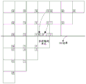
Fig. 20 is a diagram showing the positions of representative sub-blocks.
Fig. 21 is a diagram showing an example of generating a prediction region motion information list for each inter prediction mode.
Fig. 22 is a diagram showing an example of adding a prediction region merge candidate included in the long-term motion information list to the merge candidate list.
Fig. 23 is a diagram showing an example in which redundancy detection is performed only on some merging candidates.
Fig. 24 is a diagram showing an example of skipping redundancy detection for a specific merge candidate.
Fig. 25 is a diagram showing an example in which a candidate block included in the same merge processing area as the current block is set as unusable as a merge candidate.
Fig. 26 is a diagram showing a temporary motion information list.
Fig. 27 is a diagram showing an example of merging the prediction area motion information list and the temporary motion information list.
Fig. 28 and 29 are diagrams showing examples of address information of the coding-region merging candidate inclusion block.
Fig. 30 and 31 are diagrams illustrating an example in which an encoding region merge candidate having the same address information as a current block is set as a merge candidate that is not usable as the current block.
Detailed Description
Hereinafter, embodiments of the present invention will be described in detail with reference to the accompanying drawings.
Encoding and decoding of video are performed in units of blocks. For example, an encoding/decoding process such as transform, quantization, prediction, in-loop filtering, or reconstruction may be performed on an encoding block, a transform block, or a prediction block.
Hereinafter, a block to be encoded/decoded is referred to as a "current block". For example, the current block may represent an encoding block, a transform block, or a prediction block according to the current encoding/decoding process step.
In addition, the term "unit" used in the present specification denotes a basic unit for performing a specific encoding/decoding process, and "block" may be understood to mean a sample array of a predetermined size. Unless otherwise indicated, "block" and "unit" may be used interchangeably. For example, in the embodiments described later, the coding block and the coding unit may be understood to have the same meaning.
Fig. 1 is a block diagram of a video encoder (encoder) according to an embodiment of the present invention.
Referring to fig. 1, the video encoding apparatus 100 may include an image dividing part 110, prediction parts 120 and 125, a transformation part 130, a quantization part 135, a rearrangement part 160, an entropy encoding part 165, an inverse quantization part 140, an inverse transformation part 145, a filter part 150, and a memory 155.
The components shown in fig. 1 are shown separately to represent mutually different characteristic functions in the video encoding apparatus, and do not represent that the components are constituted by separate hardware or a single software component. That is, as for the respective components, in a manner of arranging the respective components so that at least two of the components are combined into one component or so that one component is divided into a plurality of components and thus functions are performed for convenience of description, such an embodiment of integrating the components and an embodiment of separating the components also belong to the scope of the present invention as long as they do not depart from the essence of the present invention.
Moreover, some of the components are not essential components for performing essential functions in the present invention, but are optional components for improving performance. The present invention may be embodied by only including components necessary for realizing the essence of the present invention except for structural elements for only improving performance, and a structure including only essential structural elements except for selective structural elements for only improving performance also falls within the scope of the present invention.
The image dividing part 110 may divide the input image into at least one processing unit. In this case, the processing Unit may be a Prediction Unit (PU), a Transform Unit (TU), or a Coding Unit (CU). The image dividing section 110 divides one image into a combination of a plurality of coding units, prediction units, and transformation units, and can encode the image by selecting one coding unit, prediction unit, and transformation unit combination based on a predetermined criterion (for example, a cost function).
For example, one image may be divided into a plurality of coding units. In order to divide an image into coding units, a recursive Tree Structure such as a Quad Tree Structure (Quad Tree Structure) may be used, and a coding unit may be divided into additional coding units, which may have children corresponding to the number of divided coding units, with one video or largest coding unit (large coding unit) as a root (root). Coding units that are no longer divided according to certain restrictions will become leaf nodes. That is, when it is assumed that one coding unit can implement only square division, one coding unit can be divided into 4 other coding units at the maximum.
Hereinafter, in an embodiment of the present invention, an encoding unit may mean a unit that performs encoding, and may also mean a unit that performs decoding.
The prediction unit in one coding unit may be divided into at least one of a square and a rectangle having the same size, or one prediction unit in one coding unit may be divided into a shape and/or a size different from that of another prediction unit.
In the case where the prediction unit performing intra prediction based on the coding unit is not the minimum coding unit, intra prediction may be performed without being divided into a plurality of prediction units nxn.
The prediction sections 120, 125 may include an inter prediction section 120 that performs inter prediction and an intra prediction section 125 that performs intra prediction. It is possible to determine whether to use inter prediction or perform intra prediction for the prediction unit, and determine specific information (e.g., an intra prediction mode, a motion vector, a reference image, etc.) based on each prediction method. In this case, the processing unit that performs prediction may be different from the processing unit that determines the prediction method and the specific contents. For example, a prediction method, a prediction mode, and the like may be determined by the prediction unit, and prediction may be performed by the transform unit. A residual value (residual block) between the generated prediction block and the original block may be input to the transform part 130. The prediction mode information, motion vector information, and the like used for prediction may be encoded in the entropy encoding unit 165 together with the residual value and transmitted to the decoder. When a specific coding mode is used, the prediction block may be generated by directly encoding the original block and transmitting to the decoder without the prediction units 120 and 125.
The inter prediction part 120 may predict the prediction unit based on information of at least one of a previous image or a next image of the current image, and in some cases, may also predict the prediction unit based on information of a part of an area that has been encoded within the current image. The inter prediction part 120 may include a reference image interpolation part, a motion prediction part, and a motion compensation part.
The reference image interpolation section receives the reference image information from the memory 155, and can generate pixel information of integer pixels or less from the reference image. For the luminance pixel, in order to generate pixel information of integer pixels or less in 1/4 pixel units, a DCT-based 8-order Interpolation Filter (DCT-based Interpolation Filter) having different Filter coefficients may be used. For the chrominance signal, in order to generate pixel information of integer pixels or less in 1/8-pixel units, a DCT-based 4-order Interpolation Filter (DCT-based Interpolation Filter) having different Filter coefficients may be used.
The motion prediction section may perform motion prediction based on the reference image interpolated by the reference image interpolation section. The method for calculating the motion vector may use various methods such as a Full Search Block Matching Algorithm (FBMA), a Three-Step Search method (TSS), a New Three-Step Search Algorithm (NTS), and the like. The motion vector may have a motion vector value in units of 1/2 pixels or 1/4 pixels based on the interpolated pixels. The current prediction unit may be predicted by adopting a different motion prediction method in the motion prediction section. The Motion Prediction method may use various methods such as a Skip (Skip) method, a Merge (Merge) method, an Advanced Motion Vector Prediction (AMVP) method, an Intra Block Copy (Intra Block Copy) method, and the like.
The intra prediction unit 125 may generate a prediction unit based on reference pixel information surrounding the current block, which is pixel information within the current image. In the case where the neighboring block of the current prediction unit is a block on which inter prediction has been performed and the reference pixel is a pixel on which inter prediction has been performed, the reference pixel included in the block on which inter prediction has been performed may be used as reference pixel information of the peripheral block on which intra prediction has been performed. That is, in the event that a reference pixel is unavailable, at least one of the available reference pixels may be used in place of the unavailable reference pixel information.
In the intra prediction, the prediction mode may have an angular prediction mode using reference pixel information in a prediction direction and a non-angular mode not using direction information when performing prediction. A mode for predicting luminance information and a mode for predicting chrominance information may be different, and in order to predict chrominance information, intra prediction mode information used for predicting luminance information or predicted luminance signal information may be applied.
When performing intra prediction, if the size of the prediction unit is the same as the size of the transform unit, intra prediction may be performed on the prediction unit based on pixels existing on the left side of the prediction unit, pixels existing on the upper left, and pixels existing on the upper side. However, when performing intra prediction, if the size of the prediction unit is different from the size of the transform unit, intra prediction may be performed using reference pixels based on the transform unit. Also, intra prediction using only N × N division for the minimum coding unit may be applied.
The Intra prediction method may generate a prediction block after applying an Adaptive Intra Smoothing (AIS) filter to the reference pixels according to a prediction mode. The type of adaptive intra smoothing filter used for the reference pixels may be different. In order to perform the intra prediction method, the intra prediction mode of the current prediction unit may be predicted from the intra prediction modes of prediction units existing at the periphery of the current prediction unit. In the case of predicting a prediction mode of a current prediction unit using mode information predicted from a peripheral prediction unit, if intra prediction modes of the current prediction unit and the peripheral prediction unit are the same, information indicating that prediction modes of the current prediction unit and the peripheral prediction unit are the same may be transmitted using predetermined flag information, and if prediction modes of the current prediction unit and the peripheral prediction unit are different, prediction mode information of a current block may be encoded by performing entropy encoding.
Also, a residual block may be generated that will include residual value information that is a difference between the prediction unit that performs prediction based on the prediction unit generated in the prediction parts 120, 125 and the original block of the prediction unit. The generated residual block may be input to the transform part 130.
In the transformation section 130, the original block and the residual block including the residual value (residual) information between the prediction units generated by the prediction sections 120 and 125 may be transformed using a transformation method such as Discrete Cosine Transform (DCT) or Discrete Sine Transform (DST). Wherein the DCT transform kernel comprises at least one of DCT2 or DCT8 and the DST transform kernel comprises DST 7. Whether DCT or DST is to be applied to transform the residual block may be determined based on intra prediction mode information of a prediction unit used to generate the residual block. The transformation of the residual block may also be skipped. A flag indicating whether to skip a transform of the residual block may be encoded. For residual blocks, luma components, or chroma components (below the 4:4:4 format) whose size is below a threshold, transform skipping may be allowed.
The quantization part 135 may quantize the value transformed into the frequency domain in the transformation part 130. The quantized coefficients may vary depending on the importance of the block or video. The values calculated in the quantization part 135 may be provided to the inverse quantization part 140 and the rearrangement part 160.
The rearrangement section 160 may perform rearrangement of the coefficient values on the quantized residual values.
The rearranging section 160 may change the 2-dimensional block shape coefficients into a 1-dimensional vector form by a Coefficient Scanning (coeffient Scanning) method. For example, the rearranging section 160 may Scan DC coefficients, even those of the high frequency domain, using a zigzag scanning (Zig-Zag Scan) method and change them into a 1-dimensional vector form. According to the size of the transform unit and the intra prediction mode, instead of the zigzag scanning, a vertical scanning that scans 2-dimensional block-shaped coefficients along the column direction and a horizontal scanning that scans 2-dimensional block-shaped coefficients along the row direction may also be used. That is, which scanning method of the zigzag scanning, the vertical direction scanning, and the horizontal direction scanning is used may be determined according to the size of the transform unit and the intra prediction mode.
The entropy encoding section 165 may perform entropy encoding based on the value calculated by the rearranging section 160. For example, the entropy Coding may use various Coding methods of Exponential Golomb code (explicit Golomb), Context-Adaptive Variable Length Coding (CAVLC), Context-Adaptive Binary Arithmetic Coding (CABAC), and the like.
The entropy encoding unit 165 may encode various types of information such as residual value coefficient information and block type information, prediction mode information, partition unit information, prediction unit information and transmission unit information, motion vector information, reference frame information, interpolation information of blocks, and filtering information of the coding units from the rearranging unit 160 and the prediction units 120 and 125.
The coefficient value of the coding unit input from the rearranging section 160 may be entropy-coded in the entropy coding section 165.
The inverse quantization unit 140 and the inverse transform unit 145 inversely quantize the plurality of values quantized by the quantization unit 135 and inversely transform the values transformed by the transform unit 130. The residual values generated by the inverse quantization unit 140 and the inverse transform unit 145 may be merged with the prediction units predicted by the motion prediction unit, the motion compensation unit, and the intra prediction unit included in the prediction units 120 and 125 to generate a Reconstructed Block (Reconstructed Block).
The Filter part 150 may include at least one of a deblocking Filter, an offset correction part, and an Adaptive Loop Filter (ALF).
The deblocking filter may remove block distortion generated in the reconstructed image due to boundaries between blocks. In order to determine whether to perform deblocking, whether to apply a deblocking filter to the current block can be determined based on pixels included in several columns or rows included in the block. In the case of applying a deblocking Filter to a block, a Strong Filter (Strong Filter) or a Weak Filter (Weak Filter) may be applied according to a required deblocking filtering strength. Also, in the process of using the deblocking filter, when vertical filtering and horizontal filtering are performed, horizontal filtering and vertical filtering can be processed in synchronization.
The offset correction section may correct an offset between the video subjected to deblocking and the original video on a pixel-by-pixel basis. In order to perform offset correction on a given image, a method may be used in which, after pixels included in a video are divided into a predetermined number of regions, a region in which offset is to be performed is determined, and the offset is applied to the corresponding region, or the offset is applied taking into account edge information of each pixel.
Adaptive Loop Filtering (ALF) may be performed based on values comparing the filtered reconstructed image and the original video. After dividing pixels included in the video into predetermined groups, filtering may be performed differently for each group by determining one filter to be used for the corresponding group. Information on whether or not to apply the adaptive loop filter and the luminance signal may be transmitted per Coding Unit (CU), and the shape of the adaptive loop filter to be applied and the filter coefficient may be different from block to block. Also, it is also possible to apply the same type (fixed type) of adaptive loop filter regardless of the characteristics of the block being applied.
The memory 155 may store the reconstructed block or image calculated by the filter part 150, and may provide the stored reconstructed block or image to the prediction parts 120 and 125 when performing inter prediction.
Fig. 2 is a block diagram of a video decoder (decoder) according to an embodiment of the present invention.
Referring to fig. 2, the video decoder 200 may include an entropy decoding part 210, a rearranging part 215, an inverse quantizing part 220, an inverse transforming part 225, a predicting part 230, a predicting part 235, a filter part 240, and a memory 245.
When a video bitstream is input from a video encoder, the input bitstream may be decoded in a reverse procedure to the video encoder.
The entropy decoding part 210 may perform entropy decoding in a reverse step to the step of performing entropy encoding in the entropy encoding part of the video encoder. For example, various methods such as Exponential Golomb code (explicit Golomb), Context-Adaptive Variable Length Coding (CAVLC), Context-Adaptive Binary Arithmetic Coding (CABAC), and the like may be applied corresponding to the method executed in the video encoder.
The entropy decoding unit 210 may decode information related to intra prediction and inter prediction performed by the encoder.
The rearranging section 215 can perform rearrangement based on a method of rearranging the bit stream entropy-decoded by the entropy decoding section 210 in the encoding section. The rearrangement may be performed by reconstructing a plurality of coefficients represented by a 1-dimensional vector form into 2-dimensional block-shaped coefficients. The rearranging section 215 receives information on the coefficient scanning performed at the encoding sections, and can perform rearrangement by a method of performing reverse scanning based on the scanning order performed at the respective encoding sections.
The inverse quantization part 220 may perform inverse quantization based on the quantization parameter provided by the encoder and the coefficient value of the rearranged block.
The inverse transform unit 225 may perform inverse discrete cosine transform and inverse discrete sine transform on the quantization result performed by the video encoder, which are inverse transforms of the transform performed by the transform unit, that is, inverse transforms of discrete cosine transform and discrete sine transform. Wherein the DCT transform kernel may include at least one of DCT2 or DCT8, and the DST transform kernel may include DST 7. Alternatively, if the transform is skipped in the video encoder, the inverse transform may not be performed in the inverse transform section 225. The inverse transform may be performed based on the transmission unit determined in the video encoder. In the inverse transform section 225 of the video decoder, a transform method (for example, DCT or DST) can be selectively performed according to a plurality of information such as a prediction method, the size of the current block, and a prediction direction.
The prediction parts 230, 235 can generate a prediction block based on information related to prediction block generation provided by the entropy decoding part 210 and previously decoded block or image information provided by the memory 245.
As described above, when intra prediction is performed in the same manner as the operation in the video encoder, if the size of the prediction unit is the same as the size of the transform unit, intra prediction is performed on the prediction unit based on the pixels existing on the left side of the prediction unit, the pixels existing on the upper left, and the pixels existing on the upper side, and if the size of the prediction unit when intra prediction is performed is different from the size of the transform unit, intra prediction may be performed using the reference pixels based on the transform unit. Also, intra prediction using only N × N division for the minimum coding unit may also be applied.
The prediction units 230 and 235 may include a prediction unit determination unit, an inter prediction unit, and an intra prediction unit. The prediction unit determination unit receives a plurality of information items such as prediction unit information, prediction mode information of an intra prediction method, and motion prediction related information of an inter prediction method, which are input from the entropy decoding unit 210, classifies the prediction units according to the current coding unit, and determines whether the prediction unit is performing inter prediction or intra prediction. The inter prediction part 230 may perform inter prediction on the current prediction unit based on information included in at least one of a previous image or a next image of the current image to which the current prediction unit belongs, using information required for inter prediction of the current prediction unit provided by the video encoder. Alternatively, inter prediction may also be performed based on information of a partial region that has been reconstructed within a current image to which a current prediction unit belongs.
In order to perform inter prediction, it can be determined on a coding unit basis which one of a Skip Mode (Skip Mode), a Merge Mode (Merge Mode), an advanced motion vector prediction Mode (AMVP Mode), and an intra block copy Mode a motion prediction method of a prediction unit included in a corresponding coding unit is.
The intra prediction part 235 may generate a prediction block based on pixel information within the current picture. When the prediction unit is a prediction unit that has performed intra prediction, intra prediction can be performed based on intra prediction mode information of the prediction unit provided by the video encoder. The Intra prediction part 235 may include an Adaptive Intra Smoothing (AIS) filter, a reference pixel interpolation part, and a DC filter. The adaptive intra smoothing filter is a part that performs filtering on reference pixels of the current block, and may determine whether to apply the filter according to a prediction mode of the current prediction unit. Adaptive intra smoothing filtering may be performed on reference pixels of a current block using a prediction mode of a prediction unit and adaptive intra smoothing filter information provided by a video encoder. If the prediction mode of the current block is a mode in which the adaptive intra smoothing filter is not performed, the adaptive intra smoothing filter may not be applied.
The reference pixel interpolation unit may generate a reference pixel in pixel units of an integer value or less by interpolating the reference pixel if a prediction mode of the prediction unit is a prediction unit that performs intra prediction based on a pixel value obtained by interpolating the reference pixel. If the prediction mode of the current prediction unit is a prediction mode in which a prediction block is generated in such a manner that reference pixels are not interpolated, the reference pixels may not be interpolated. If the prediction mode of the current block is the DC mode, the DC filter may generate the prediction block through filtering.
The reconstructed block or image may be provided to the filter part 240. The filter part 240 may include a deblocking filter, an offset correction part, and an ALF.
Information regarding whether a deblocking filter is applied to a corresponding block or image and information regarding whether a strong filter or a weak filter is applied when the deblocking filter is applied may be received from a video encoder. Information related to the deblocking filter provided by the video encoder is received from the deblocking filter of the video decoder, and deblocking filtering may be performed on the corresponding block at the video decoder.
The offset correction section can perform offset correction on the reconstructed video based on the type of offset correction used for the video at the time of encoding, the offset information, and the like.
The ALF may be applied to the encoding unit based on information related to whether the ALF is applied, ALF coefficient information, and the like, provided by the encoder. Such ALF information may be provided by being included in a specific parameter set.
The memory 245 stores the reconstructed image or block so that the image or block can be used as a reference image or reference block, and can provide the reconstructed image to the output.
Fig. 3 is a diagram illustrating a basic coding tree unit of an embodiment of the present invention.
The largest sized coding block may be defined as a coding tree block. One picture can be divided into a plurality of Coding Tree Units (CTUs). A Coding tree Unit is a Coding Unit with the Largest size, and may also be referred to as a Largest Coding Unit (LCU). Fig. 3 shows an example of dividing one image into a plurality of coding tree units.
The size of the coding tree unit may be defined in a picture level or a sequence level. For this, information representing the size of the coding tree unit may be signaled by a picture parameter set or a sequence parameter set.
For example, the size of the coding tree unit of the entire image within the sequence may be set to 128 × 128. Alternatively, either of 128 × 128 or 256 × 256 of the image level may be determined as the size of the coding tree unit. For example, the size of the coding tree unit in the first image may be set to 128 × 128, and the size of the coding tree unit in the second image may be set to 256 × 256.
The encoded blocks may be generated by dividing the encoding tree unit. The encoding block represents a basic unit for performing encoding/decoding processing. For example, prediction or transformation may be performed or a prediction encoding mode may be determined per different encoding block. Here, the prediction encoding mode indicates a method of generating a prediction image. For example, the Prediction coding mode may include Intra Prediction (Intra Prediction), Inter Prediction (Inter Prediction), Current Picture reference (CPR, or Intra Block Copy (IBC)), or Combined Prediction (Combined Prediction). For an encoding block, a prediction block related to the encoding block may be generated using at least one prediction coding mode of intra prediction, inter prediction, current picture reference, or combined prediction.
Information indicating the prediction encoding mode of the current block may be signaled through a bitstream. For example, the information may be a 1-bit flag indicating whether the prediction encoding mode is an intra mode or an inter mode. The current picture reference or the combined prediction may be used only if the prediction encoding mode of the current block is determined as the inter mode.
The current picture reference is used to set the current picture as a reference picture and obtain a prediction block of the current block from an already encoded/decoded region within the current picture. Wherein the current picture means a picture including the current block. Information indicating whether to apply the current picture reference to the current block may be signaled through a bitstream. For example, the information may be a 1-bit flag. When the flag is true, the prediction encoding mode of the current block may be determined as the current picture reference, and when the flag is false, the prediction mode of the current block may be determined as inter prediction.
Alternatively, the prediction encoding mode of the current block may be determined based on the reference picture index. For example, when the reference picture index points to the current picture, the predictive coding mode of the current block may be determined as the current reference picture. When the reference picture index points to other pictures instead of the current picture, the prediction encoding mode of the current block may be determined as inter prediction. That is, the current picture reference is a prediction method using information of an already encoded/decoded region within the current picture, and the inter prediction is a prediction method using information of another picture that has been already encoded/decoded.
The combined prediction indicates an encoding mode in which two or more of intra prediction, inter prediction, and current picture reference are combined. For example, in the case of applying combined prediction, a first prediction block may be generated based on one of intra prediction, inter prediction, or current picture reference, and a second prediction block may be generated based on the other. If the first prediction block and the second prediction block are generated, the final prediction block may be generated by an average operation or a weighted sum operation of the first prediction block and the second prediction block. Information indicating whether the combined prediction is applied may be signaled through a bitstream. The information may be a 1-bit flag.
Fig. 4 is a diagram illustrating various partition types of a coding block.
The coding block may be divided into a plurality of coding blocks based on a quadtree division, a binary tree division, or a ternary tree division. The divided coding block may be further divided into a plurality of coding blocks again based on quad tree division, binary tree division or ternary tree division.
Quad tree division refers to a division technique that divides a current block into 4 blocks. As a result of the quadtree division, the current block may be divided into 4 square partitions (refer to "SPLIT _ QT" in part (a) of fig. 4).
Binary tree partitioning refers to a partitioning technique that partitions a current block into 2 blocks. The process of dividing the current block into two blocks in the vertical direction (i.e., using a vertical line crossing the current block) may be referred to as a vertical direction binary tree division, and the process of dividing the current block into two blocks in the horizontal direction (i.e., using a horizontal line crossing the current block) may be referred to as a horizontal direction binary tree division. The current block may be partitioned into 2 non-square partitions after undergoing binary tree partitioning. "SPLIT _ BT _ VER" in the part of fig. 4(b) represents a vertical direction binary tree division result, and "SPLIT _ BT _ HOR" in the part of fig. 4(c) represents a horizontal direction binary tree division result.
The ternary tree division refers to a division technique of dividing a current block into 3 blocks. The process of dividing the current block into three blocks in the vertical direction (i.e., using two vertical lines crossing the current block) may be referred to as vertical-direction trie division, and the process of dividing the current block into three blocks in the horizontal direction (i.e., using two horizontal lines crossing the current block) may be referred to as horizontal-direction trie division. The current block may be divided into 3 non-square partitions after undergoing the ternary tree division. In this case, the width/height of the partition located at the center of the current block may be 2 times the width/height of the other partitions. "SPLIT _ TT _ VER" in the section (d) of fig. 4 represents the vertical-direction ternary-tree division result, and "SPLIT _ TT _ HOR" in the section (e) of fig. 4 represents the horizontal-direction ternary-tree division result.
The number of divisions of the coding tree unit may be defined as a division Depth (partioning Depth). The maximum partition depth of the coding tree unit may be determined at a sequence or image level. Thus, the maximum division depth of the coding tree unit may become different according to different sequences or images.
Alternatively, the maximum partitioning depth for each of the plurality of partitioning techniques may be determined separately. For example, the maximum partition depth that allows quadtree partitioning may be different from the maximum partition depth that allows binary tree partitioning and/or ternary tree partitioning.
The encoder may signal information representing at least one of a partition shape or a partition depth of the current block through a bitstream. The decoder may determine a partition shape and a partition depth of the coding tree unit based on information parsed from the bitstream.
Fig. 5 is a diagram illustrating a division pattern of a coding tree unit.
The process of dividing the coding blocks using a quadtree division, binary Tree division, and/or ternary Tree division technique may be referred to as Multi-Tree division (Multi Tree Partitioning).
An encoding block generated by applying a multi-tree partition to an encoding block may be referred to as a plurality of downstream encoding blocks. When the division depth of the coding block is k, the division depth of a plurality of downstream coding blocks is set to be k + 1.
On the other hand, for a plurality of coding blocks with a division depth of k +1, the coding block with the division depth of k may be referred to as an upstream coding block.
The partition type of the current coding block may be determined based on at least one of a partition shape of an upstream coding block or a partition type of an adjacent coding block. Wherein the adjacent coding block is adjacent to the current coding block, which may include at least one of an upper adjacent block, a left adjacent block, or an adjacent block adjacent to an upper left corner of the current coding block. The partition type may include at least one of whether to partition a quadtree, whether to partition a binary tree, a binary tree partition direction, whether to partition a ternary tree, or a ternary tree partition direction.
In order to determine the division shape of the coding block, information indicating whether the coding block is divided or not may be signaled through a bit stream. The information is a 1-bit flag 'split _ cu _ flag', and when the flag is true, it indicates that the coding block is divided by a multi-way tree division technique.
When the 'split _ cu _ flag' is true, information indicating whether the coding block is divided by the quadtree may be signaled through the bitstream. The information is a 1-bit flag "split _ qt _ flag", and when the flag is true, a coding block can be divided into 4 blocks.
For example, generation of 4 coding blocks with a division depth of 1 as a coding tree unit is divided by a quadtree is illustrated in the example shown in fig. 5. Also, it is illustrated that the quad-tree splitting is applied again to the first and fourth encoding blocks among the 4 encoding blocks generated as a result of the quad-tree splitting. Finally, 4 coded blocks with a partition depth of 2 may be generated.
And, the coding block having the division depth of 3 may be generated by applying the quadtree division again to the coding block having the division depth of 2.
When the quadtree division is not applied to the coding block, whether to perform the binary tree division or the ternary tree division on the coding block may be determined by considering at least one of a size of the coding block, whether the coding block is located at an image boundary, a maximum division depth, or a division shape of an adjacent block. When it is determined to perform binary tree splitting or ternary tree splitting on the encoded block, information indicating a splitting direction may be signaled through a bit stream. The information may be a 1-bit flag "mtt _ split _ cu _ vertical _ flag". Whether the division direction is the vertical direction or the horizontal direction may be determined based on the flag. In addition, information indicating which of binary tree partitioning or ternary tree partitioning is applied to the coding block may be signaled through a bit stream. The information may be a 1-bit flag "mtt _ split _ cu _ binary _ flag". Whether to apply binary tree partitioning or ternary tree partitioning to the coding block may be determined based on the flag.
For example, it is illustrated in the example shown in fig. 5 that the vertical direction binary tree division is applied to the coding blocks whose division depth is 1, the vertical direction ternary tree division is applied to the left coding block and the vertical direction binary tree division is applied to the right coding block among the coding blocks generated as a result of the division.
Inter prediction refers to a prediction encoding mode for predicting a current block using information of a previous image. For example, a block (hereinafter, referred to as a Collocated block) at the same position as the current block in the previous image may be set as the prediction block of the current block. Hereinafter, a Prediction Block generated based on a Block having the same position as the current Block is referred to as a Collocated Prediction Block (Collocated Prediction Block).
On the other hand, if an object existing in a previous image has moved to other positions in the current image, the motion of the object can be used to efficiently predict the current block. For example, if the moving direction and size of the object can be known by comparing the previous image and the current image, a prediction block (or a prediction image) of the current block can be generated in consideration of motion information of the object. Hereinafter, a prediction block generated using motion information may be referred to as a motion prediction block.
A residual block may be generated by subtracting the prediction block from the current block. In this case, when there is motion of an object, it is possible to reduce the energy of the residual block by using a motion prediction block instead of the same-position prediction block, so that the compression performance of the residual block can be improved.
As described above, the process of generating a prediction block using motion information may be referred to as motion compensated prediction. In most inter prediction, a prediction block may be generated based on motion compensated prediction.
The motion information may include at least one of a motion vector, a reference picture index, a prediction direction, or a bidirectional weight value index. The motion vector represents the moving direction and size of the object. The reference picture index specifies a reference picture of a current block among a plurality of reference pictures included in the reference picture list. The prediction direction refers to any one of unidirectional L0 prediction, unidirectional L1 prediction, or bidirectional prediction (L0 prediction and L1 prediction). At least one of the motion information of the L0 direction or the motion information of the L1 direction may be used according to the prediction direction of the current block. The bi-directional weight-value index specifies the weight values used for the L0 prediction block and the weight values applied to the L1 prediction block.
Fig. 6 is a flowchart of an inter prediction method according to an embodiment of the present invention.
Referring to fig. 6, the inter prediction method includes the steps of: determining an inter prediction mode of a current block (S601); obtaining motion information of the current block according to the determined inter prediction mode (S602); and performing motion compensated prediction on the current block based on the obtained motion information (S603).
Inter prediction modes represent various techniques for determining motion information of a current block, and may include an inter prediction mode using translational (Translation) motion information and an inter prediction mode using Affine (Affine) motion information. For example, the inter prediction modes using translational motion information may include a merge mode and an advanced motion vector prediction mode, and the inter prediction modes using affine motion information may include an affine merge mode and an affine motion vector prediction mode. According to the inter prediction mode, motion information of the current block may be determined based on a neighboring block adjacent to the current block or information parsed from a bitstream.
Hereinafter, the inter prediction method using affine motion information will be described in detail.
Fig. 7 is a diagram illustrating a non-linear motion of an object.
The motion of objects within the video may be non-linear. For example, as shown in the example of fig. 7, non-linear motion of the object may occur such as Zoom-in, Zoom-out, Rotation, or affine transformation. When a non-linear motion of an object occurs, the motion of the object cannot be effectively represented by translating the motion vector. Thus, at a portion where the nonlinear motion of the object occurs, the translational motion can be replaced by using the affine motion, thereby improving the encoding efficiency.
Fig. 8 is a flowchart illustrating an affine motion based inter prediction method according to an embodiment of the present invention.
Whether to apply an affine motion based inter prediction technique to the current block may be determined based on information parsed from the bitstream. Specifically, whether to apply the affine motion based inter prediction technique to the current block may be determined based on at least one of a flag indicating whether to apply an affine merge mode to the current block or a flag indicating whether to apply an affine motion vector prediction mode to the current block.
When the affine motion based inter prediction technique is applied to the current block, an affine motion model of the current block may be determined (S801). The affine motion model may be determined by at least one of a 6-parameter affine motion model or a 4-parameter affine motion model. The 6-parameter affine motion model uses 6 parameters to represent affine motion, and the 4-parameter affine motion model uses 4 parameters to represent affine motion.
[ EQUATION 1]
vx=ax-by+e
vy=cx+dy+f
When affine motion is represented using 6 parameters, complex motion can be represented, but the number of bits required to encode each parameter increases, which may reduce encoding efficiency. Thus, affine motion can also be represented using 4 parameters. Equation 2 is the case where affine motion is represented using 4 parameters.
[ equation 2]
vx=ax-by+e
vy=bx+ay+f
Information for determining an affine motion model of the current block may be encoded and may be signaled through a bitstream. For example, the information may be a 1-bit flag "affine _ type _ flag". A value of 0 for the flag indicates that a 4-parameter affine motion model is applied, and a value of 1 for the flag indicates that a 6-parameter affine motion model is applied. The flags may be encoded in units of slices, tiles, or blocks (e.g., coding blocks or coding tree units). When the flag is signaled at the slice level, the affine motion model determined at the slice level may be applied to all blocks belonging to the slice.
Alternatively, an affine motion model of the current block may be determined based on an affine inter prediction mode of the current block. For example, when the affine merge mode is applied, the affine motion model of the current block may be determined as a 4-parameter motion model. On the other hand, when the affine motion vector prediction mode is applied, information for determining an affine motion model of the current block may be encoded and may be signaled through a bitstream. For example, when the affine motion vector prediction mode is applied to the current block, an affine motion model of the current block may be determined based on a 1-bit flag "affine _ type _ flag".
Next, an affine seed vector for the current block may be derived (S802). When a 4-parameter affine motion model is selected, motion vectors on two control points of the current block can be derived. On the other hand, when the 6-parameter affine motion model is selected, motion vectors on three control points of the current block can be derived. The motion vector on the control point may be referred to as an affine seed vector. The control point may include at least one of an upper left corner, an upper right corner, or a lower left corner of the current block.
Fig. 9 is a diagram showing an example of affine seed vectors for each affine motion model.
In a 4-parameter affine motion model, affine seed vectors can be derived that are related to two of the top left, top right, or bottom left corners. For example, as shown in the example of fig. 9(a), when the 4-parameter affine motion model is selected, it is possible to select a motion vector by using an affine seed vector sv associated with the upper left corner of the current block (e.g., upper left sample (x0, y0))0And with the current blockTop right corner (e.g., top right sample (x1, y1)) related affine seed vector sv1To derive an affine vector. An affine seed vector associated with the lower left corner may also be used in place of the affine seed vector associated with the upper left corner, or an affine seed vector associated with the lower left corner may also be used in place of the affine seed vector associated with the upper right corner.
In a 6-parameter affine motion model, affine seed vectors can be derived that relate to the top left corner, top right corner, and bottom left corner. For example, as shown in the example of fig. 9(b), when the 6-parameter affine motion model is selected, it is possible to select a motion vector by using an affine seed vector sv associated with the upper left corner of the current block (e.g., upper left sample (x0, y0))0Affine seed vector sv relating to the upper right corner of the current block (e.g., upper right sample (x1, y1))1And affine seed vector sv associated with the top left corner of the current block (e.g., top left sample (x2, y2))2To derive an affine vector.
In the embodiment described later, under the 4-parameter affine motion model, the affine seed vectors of the upper left control point and the upper right control point are referred to as a first affine seed vector and a second affine seed vector, respectively. In the later-described embodiments using the first affine seed vector and the second affine seed vector, at least one of the first affine seed vector and the second affine seed vector may be replaced with the affine seed vector of the lower left control point (third affine seed vector) or the affine seed vector of the lower right control point (fourth affine seed vector).
In the 6-parameter affine motion model, affine seed vectors of the upper left control point, the upper right control point, and the lower left control point are referred to as a first affine seed vector, a second affine seed vector, and a third affine seed vector, respectively. In the later-described embodiments using the first, second, and third affine seed vectors, at least one of the first, second, and third affine seed vectors may be replaced with an affine seed vector of the lower-right control point (fourth affine seed vector).
Affine seed vectors may be used to derive affine vectors by different sub-blocks (S803). Wherein the affine vector represents a translational motion vector derived based on an affine seed vector. The affine vector of the sub-block may be referred to as an affine sub-block motion vector or a sub-block motion vector.
Fig. 10 is a diagram showing an example of affine vectors of sub-blocks under a 4-parameter motion model.
An affine vector for the sub-block may be derived based on the position of the control point, the position of the sub-block, and the affine seed vector. For example, equation 3 represents an example of deriving an affine sub-block vector.
[ equation 3]


In the formula 3, (x, y) represents the position of the subblock. Wherein the position of the sub-block represents a position of a reference sample included in the sub-block. The reference sample may be a sample located at the upper left corner of the sub-block or a sample located at the center position in at least one of the x-axis or y-axis coordinates. (x)0,y0) Represents the position of the first control point, and (sv)0x,sv0y) Representing a first affine seed vector. In addition, (x)1,y1) Indicates the position of the second control point, and (sv)1x,sv1y) Representing a second affine seed vector.
When the first control point and the second control point respectively correspond to the upper left corner and the upper right corner of the current block, x may be set1-x0Is set to the same value as the width of the current block.
Thereafter, motion compensated prediction may be performed on each sub-block using the affine vector of each sub-block (S804). After performing the motion compensated prediction, a prediction block may be generated with respect to each sub-block. The prediction block of the sub-block may be set as the prediction block of the current block.
Next, the inter prediction method using the translational motion information will be described in detail.
The motion information of the current block may be derived from motion information of other blocks of the current block. Wherein the other block may be a block that is encoded/decoded with inter prediction more preferentially than the current block. A case where the motion information of the current block is set to be the same as the motion information of the other blocks may be defined as the merge mode. And, a case in which the motion vector of the other block is set as the predictor of the motion vector of the current block may be defined as a motion vector prediction mode.
Fig. 11 is a flowchart of a process of deriving motion information of a current block in a merge mode.
A merge candidate of the current block may be derived (S1101). The merge candidate of the current block may be derived from a block encoded/decoded in inter prediction before the current block.
Fig. 12 is a diagram showing an example of a candidate block for deriving a merge candidate.
The candidate block may include at least one of a neighboring block including samples adjacent to the current block or a non-neighboring block including samples not adjacent to the current block. Hereinafter, a sample used for determining a candidate block is designated as a reference sample. In addition, reference samples adjacent to the current block are referred to as adjacent reference samples, and reference samples not adjacent to the current block are referred to as non-adjacent reference samples.
The neighboring reference samples may be included in a neighboring column of a leftmost column of the current block or a neighboring line of an uppermost line of the current block. For example, if the coordinates of the top-left sample of the current block are (0, 0), at least one of a block including the reference sample at the (-1, H-1) position, a block including the reference sample at the (W-1, -1) position, a block including the reference sample at the (W, -1) position, a block including the reference sample at the (-1, H) position, or a block including the reference sample at the (-1, -1) position may be used as the candidate block. Referring to the drawing, neighboring blocks having indexes of 0 to 4 may be used as candidate blocks.
The non-neighboring reference samples represent samples having at least one of an x-axis distance or a y-axis distance between reference samples neighboring the current block having a predefined value. For example, at least one of a block including a reference sample whose x-axis distance from the left reference sample is a predefined value, a block including a non-adjacent sample whose y-axis distance from the upper reference sample is a predefined value, or a block including a non-adjacent sample whose x-axis distance from the upper left reference sample and y-axis distance are predefined values may be used as a candidate block. The predefined value may be an integer of 4, 8, 12, 16, etc. Referring to the drawing, at least one of blocks having indexes 5 to 26 may be used as a candidate block.
Samples that are not on the same vertical, horizontal, or diagonal line as the neighboring reference sample may be set as non-neighboring reference samples.
Fig. 13 is a diagram showing the position of the reference sample.
As an example shown in fig. 13, the x-coordinate of the upper non-adjacent reference sample may be set to be different from the x-coordinate of the upper adjacent reference sample. For example, when the position of the upper adjacent reference sample is (W-1, -1), the position of the upper non-adjacent reference sample spaced apart from the upper adjacent reference sample by N along the y-axis may be set to ((W/2) -1, -1-N), and the position of the upper non-adjacent reference sample spaced apart from the upper adjacent reference sample by 2N along the y-axis may be set to (0, -1-2N). That is, the location of the non-neighboring reference sample may be determined based on the location of the neighboring reference sample and the distance to the neighboring reference sample.
Hereinafter, a candidate block containing neighboring reference samples among the candidate blocks is referred to as a neighboring block, and a block containing non-neighboring reference samples is referred to as a non-neighboring block.
When the distance between the current block and the candidate block is greater than or equal to a threshold, the candidate block may be set as unavailable as a merge candidate. The threshold may be determined based on the size of the coding tree unit. For example, the threshold may be set to a height of the coding tree unit (ctu _ height), or a value obtained by adding or subtracting an offset value to or from the height of the coding tree unit (e.g., ctu _ height ± N). The offset value N is a predefined value in the encoder and decoder and may be set to 4, 8, 16, 32, or ctu _ height.
The candidate block may be determined to be unusable as a merge candidate when a difference between y-axis coordinates of the current block and y-axis coordinates of samples included in the candidate block is greater than a threshold.
Alternatively, a candidate block that does not belong to the same coding tree unit as the current block may be set as unavailable as a merge candidate. For example, when the reference sample exceeds an upper boundary of the coding tree unit to which the current block belongs, the candidate block including the reference sample may be set as unavailable as the merge candidate.
If a plurality of candidate blocks are determined to be unavailable as merging candidates when the upper boundary of the current block is adjacent to the upper boundary of the coding tree unit, the encoding/decoding efficiency of the current block may be reduced. In order to solve the above problem, candidate blocks may be set such that the number of candidate blocks located above the current block is greater than the number of candidate blocks located to the left of the current block.
Fig. 14 is a diagram showing an example of a candidate block for deriving a merge candidate.
As an example shown in fig. 14, an upper square belonging to the top N block columns of the current block and a left block belonging to the left M block columns of the current block may be set as candidate blocks. At this time, by setting M to be larger than N, the number of left candidate blocks can be set to be larger than the number of above candidate blocks.
For example, the difference between the y-axis coordinate of the reference sample within the current block and the y-axis coordinate of the upper block available as a candidate block may be set not to exceed N times the height of the current block. In addition, a difference value between x-axis coordinates of a reference sample within the current block and x-axis coordinates of a left block available as a candidate block may be set not to exceed M times the width of the current block.
For example, as in the example shown in fig. 14, it is shown that blocks belonging to the upper two block columns of the current block and blocks belonging to the left five block columns of the current block are set as candidate blocks.
As another example, when the candidate block does not belong to the same coding tree unit as the current block, the merge candidate may be derived using a block belonging to the same coding tree unit as the current block or a block including reference samples adjacent to a boundary of the coding tree unit instead of the candidate block.
Fig. 15 is a diagram showing an example of changing the position of the reference sample.
When a reference sample is included in a coding tree unit different from the current block and the reference sample is not adjacent to a boundary of the coding tree unit, a candidate block reference sample may be determined using a reference sample adjacent to the boundary of the coding tree unit instead of the reference sample.
For example, in the examples shown in fig. 15(a) and 15(b), when the upper boundary of the current block and the upper boundary of the coding tree unit contact each other, the reference samples above the current block belong to a coding tree unit different from the current block. The reference samples that are not adjacent to the upper boundary of the coding tree unit among the reference samples belonging to a coding tree unit different from the current block may be replaced by samples adjacent to the upper boundary of the coding tree unit.
For example, as shown in the example of fig. 15(a), the reference sample at position 6 is replaced with a sample at position 6 'of the upper boundary of the coding tree unit, and as shown in the example of fig. 15(b), the reference sample at position 15 is replaced with a sample at position 15' of the upper boundary of the coding tree unit. At this time, the y-coordinate of the replacement sample may be changed to the adjacent position of the coding tree unit, and the x-coordinate of the replacement sample may be set to be the same as the reference sample. For example, a sample at the 6 'position may have the same x-coordinate as a sample at the 6 position, and a sample at the 15' position may have the same x-coordinate as a sample at the 15 position.
Alternatively, a value obtained by adding or subtracting an offset value to or from the x coordinate of the reference sample may be set as the x coordinate of the replacement sample. For example, when x-coordinates of a neighboring reference sample and a non-neighboring reference sample located above the current block are the same, a value obtained by adding or subtracting an offset value to or from the x-coordinate of the reference sample may be set as the x-coordinate of the replacement sample. This is to prevent a replacement sample for replacing a non-neighboring reference sample from being in the same position as other non-neighboring reference samples or neighboring reference samples.
Fig. 16 is a diagram showing an example of changing the position of the reference sample.
When a reference sample, which is included in a coding tree unit different from the current block and is not adjacent to the boundary of the coding tree unit, is replaced with a sample located at the boundary of the coding tree unit, a value obtained by adding or subtracting an offset value to or from the x-coordinate of the reference sample may be set as the x-coordinate of the replacement sample.
For example, in the example shown in FIG. 16, the reference sample at position 6 and the reference sample at position 15 may be replaced with the sample at position 6 'and the sample at position 15', respectively, having the same y-coordinate as the row adjacent to the upper boundary of the coding tree cell. At this time, the x-coordinate of the sample at the 6 'position may be set to a value differing by W/2 from the x-coordinate of the reference sample at the 6 position, and the x-coordinate of the sample at the 15' position may be set to a value differing by W-1 from the x-coordinate of the reference sample at the 15 position.
Unlike the examples shown in fig. 15 and 16, the y-coordinate of the line located above the uppermost line of the current block or the y-coordinate of the upper boundary of the coding tree unit may also be set as the y-coordinate of the replacement sample.
Although not shown, samples instead of reference samples may also be determined based on the left boundary of the coding tree unit. For example, when a reference sample is not included in the same coding tree unit as the current block and is not adjacent to the left boundary of the coding tree unit, the reference sample may be replaced with a sample adjacent to the left boundary of the coding tree unit. At this time, the replacement sample may have the same y-coordinate as the reference sample, or may have a y-coordinate obtained by adding or subtracting an offset value to the y-coordinate of the reference sample.
Thereafter, a block containing the replacement samples may be set as a candidate block, and a merge candidate of the current block may be derived based on the candidate block.
The merge candidate may also be derived from a temporally neighboring block included in a different image than the current block. For example, the merging candidate may be derived from the co-located block included in the co-located image.
The motion information of the merge candidate may be set to be the same as the motion information of the candidate block. For example, at least one of a motion vector of the candidate block, a reference picture index, a prediction direction, or a bidirectional weight value index may be set as the motion information of the merge candidate.
A merge candidate list including merge candidates may be generated (S1102). The merge candidates may be classified into neighboring merge candidates derived from neighboring blocks adjacent to the current block, and non-neighboring merge candidates derived from non-neighboring blocks.
The indexes of the plurality of merge candidates within the merge candidate list may be allocated in a predetermined order. For example, the index assigned to the neighboring merge candidate may have a smaller value than the index assigned to the non-neighboring merge candidate. Alternatively, an index may be assigned to each merge candidate based on the index of each block shown in fig. 12 or fig. 14.
When a plurality of merge candidates are included in the merge candidate list, at least one of the plurality of merge candidates may be selected (S1103). At this time, information indicating whether the motion information of the current block is derived from the neighboring merge candidates may be signaled through a bitstream. The information may be a 1-bit flag. For example, a syntax element isaddannontmergeflag indicating whether motion information of the current block is derived from neighboring merge candidates may be signaled through a bitstream. When the value of the syntax element isadjancentMergeFlag is 1, motion information of the current block may be derived based on the neighbor merge candidates. On the other hand, when the value of the syntax element isadjancentMergeFlag is 0, motion information of the current block may be derived based on non-neighboring merge candidates.
Table 1 shows a syntax table including a syntax element isAdjancentMergeFlag.
TABLE 1


Information for specifying any one of the plurality of merging candidates may be signaled through a bitstream. For example, information indicating any one index of the merge candidates included in the merge candidate list may be signaled through a bitstream.
When isadjacentmergflag is 1, a syntax element merge _ idx for determining any one of neighbor merge candidates may be signaled. The maximum value of the syntax element merge _ idx may be set to a value differing from the number of neighboring merge candidates by 1.
When isadjacentmergflag is 0, a syntax element NA _ merge _ idx for determining any one of non-adjacent merge candidates may be signaled. The syntax element NA _ merge _ idx indicates a value obtained by subtracting the index of the non-adjacent merge candidate from the number of adjacent merge candidates. The decoder may select a non-neighboring merge candidate by adding the index determined according to NA _ merge _ idx to the number of neighboring merge candidates.
When the number of merge candidates included in the merge candidate list is less than a threshold, the merge candidate included in the prediction region motion information list may be added to the merge candidate list. Wherein the threshold may be a value obtained by subtracting an offset from the number of the largest merge candidates or the number of the largest merge candidates that the merge candidate list may include. The offset may be an integer such as 1 or 2. The inter motion information list may include merge candidates derived based on a block encoded/decoded before the current block.
The prediction region motion information list includes merging candidates derived from blocks encoded/decoded based on inter prediction in the current image. For example, the motion information of the merge candidate included in the prediction region motion information list may be set equal to the motion information of the block encoded/decoded based on the inter prediction. Wherein the motion information may include at least one of a motion vector, a reference picture index, a prediction direction, or a bidirectional weight value index.
For convenience of explanation, the merge candidate included in the prediction region motion information list is referred to as a prediction region merge candidate.
The maximum number of merge candidates that the prediction region motion information list may include may be predefined by the encoder and decoder. For example, the prediction region motion information list may include a maximum number of merge candidates that may be 1, 2, 3, 4, 5, 6, 7, 8, or more (e.g., 16).
Alternatively, information indicating the maximum number of merge candidates that the prediction region motion information list may include may be signaled through a bitstream. The information is signaled at the sequence level, picture level, or slice level. The information may indicate a maximum number of merge candidates that the prediction region motion information list may include. Alternatively, the information may indicate a difference between the maximum number of merge candidates that the prediction region motion information list may include and the maximum number of merge candidates that the merge candidate list may include.
Alternatively, the maximum number of merging candidates in the prediction region motion information list may be determined according to the size of an image, the size of a slice, or the size of a coding tree unit.
The prediction region motion information list may be initialized in units of an image, a slice (slice), a tile (tile), a brick (brick), a coding tree unit, or a coding tree unit line (row or column). For example, if a slice is initialized, the prediction region motion information list is also initialized, and the prediction region motion information list may not include any merge candidate.
Alternatively, information indicating whether the prediction region motion information list is to be initialized may be signaled through a bitstream. The information may be signaled at the chip, tile, brick, or block level. The configured prediction region motion information list may be used before the information indicates that the prediction region motion information list is to be initialized.
Alternatively, the information on the initial prediction region merging candidate may be signaled through a picture parameter set or slice header. The prediction region motion information list may include an initial prediction region merging candidate even if the slice is initialized. Therefore, the prediction region merging candidate may be used for a block that is the first encoding/decoding target in the slice.
Alternatively, the prediction region merge candidate included in the prediction region motion information list of the previous coding tree unit may be set as the initial prediction region merge candidate. For example, among the prediction region merge candidates included in the prediction region motion information list of the previous coding tree unit, a prediction region merge candidate with the smallest index or a prediction region merge candidate with the largest index may be set as the initial prediction region merge candidate.
The blocks are encoded/decoded according to an encoding/decoding order, and the blocks encoded/decoded based on the inter prediction may be sequentially set as prediction region merging candidates according to the encoding/decoding order.
Fig. 17 is a flowchart illustrating a process for updating the prediction area motion information list.
When inter prediction is performed on the current block (S1701), a prediction region merge candidate may be derived based on the current block (S1702). The motion information of the prediction region merge candidate may be set equal to the motion information of the current block.
When the prediction region motion information list is empty (S1703), a prediction region merge candidate derived based on the current block may be added to the prediction region motion information list (S1704).
When the prediction region motion information list already includes the prediction region merge candidate (S1703), the motion information of the current block (or the prediction region merge candidate derived based on the current block) may be redundantly detected (S1705). The redundancy check is for determining whether motion information of a prediction region merge candidate, which has been stored in a prediction region motion information list, is identical to motion information of a current block. Redundancy detection may be performed on all prediction region merging candidates that have been stored in the prediction region motion information list. Alternatively, the redundancy detection may be performed on a prediction region merge candidate whose index is greater than or less than a threshold among the prediction region merge candidates already stored in the prediction region motion information list.
When an inter prediction merge candidate having the same motion information as that of the current block is not included, a prediction region merge candidate derived based on the current block may be added to the prediction region motion information list (S1708). Whether the inter-frame merging candidates are the same may be determined based on whether the motion information (e.g., the motion vector and/or the reference picture index, etc.) of the inter-frame merging candidates are the same.
In this case, when the maximum number of prediction region merge candidates has been stored in the prediction region motion information list (S1706), the oldest prediction region merge candidate is deleted (S1707), and a prediction region merge candidate derived based on the current block may be added to the prediction region motion information list (S1708). Here, the earliest prediction region merge candidate may be a prediction region merge candidate with the largest index or a prediction region merge candidate with the smallest index.
Each prediction region merging candidate may be identified by an index. When a prediction region merge candidate derived from the current block is added to the prediction region motion information list, a minimum index (e.g., 0) is allocated to the prediction region merge candidate, and the index of the stored prediction region merge candidate may be increased by 1. In this case, if the prediction region motion information list has stored the maximum number of inter prediction merge candidates, the prediction region merge candidate having the largest index is removed.
Alternatively, when a prediction region merge candidate derived from the current block is added to the prediction region motion information list, the largest index may be assigned to the prediction region merge candidate. For example, when the number of inter prediction merging candidates already stored in the prediction region motion information list is less than the maximum value, an index having the same value as the number of already stored inter prediction merging candidates may be allocated to the prediction region merging candidates. Alternatively, when the number of inter prediction merging candidates already stored in the prediction region motion information list is the same as the maximum value, an index obtained by subtracting 1 from the maximum value may be allocated to the prediction region merging candidate. Further, the prediction region merge candidate having the smallest index is removed, and the indexes of the remaining stored prediction region merge candidates may be decreased by 1.
Fig. 18 is a diagram illustrating an embodiment of updating a prediction region merge candidate list.
It is assumed that the largest index is allocated to the prediction region merge candidate when the prediction region merge candidate derived from the current block is added to the prediction region merge candidate list. Further, it is assumed that the maximum number of prediction region merging candidates have already been stored in the prediction region merging candidate list.
When a prediction region merge candidate HmvpCand [ n +1] derived from the current block is added to the prediction region merge candidate list HmvpCandList, the prediction region merge candidate HmvpCand [0] having the smallest index among the stored prediction region merge candidates is deleted, and the indexes of the remaining prediction region merge candidates may be decreased by 1. In addition, the index of the prediction region merging candidate hmvpland [ n +1] derived from the current block may be set to the maximum value (n in the example shown in fig. 18).
When the same prediction region merge candidate as the prediction region merge candidate derived based on the current block has been stored (S1705), the prediction region merge candidate derived based on the current block may not be added to the prediction region motion information list (S1709).
Alternatively, when a prediction region merge candidate derived based on the current block is added to the prediction region motion information list, a prediction region merge candidate that is already stored and identical to the prediction region merge candidate may be removed. In this case, the same effect as newly updating the index of the already stored prediction region merging candidate is obtained.
Fig. 19 is a diagram showing an example of updating the index of the stored prediction region merge candidate.
When the index of the inter prediction merge candidate stored to be the same as the prediction region merge candidate mvCand derived based on the current block is hdx, the index of the inter prediction merge candidate stored to be the same as the index of the inter prediction merge candidate is deleted, and the index of the inter prediction merge candidate having an index greater than hdx may be decreased by 1. For example, in the example shown in fig. 19, it is shown that hmvpland [2] that is the same as mvCand is deleted from the prediction region motion information list HvmpCand list, and the indexes of hmvpland [3] to hmvpland [ n ] are each reduced by 1.
In addition, a prediction region merge candidate mvCand derived based on the current block may be added to the end of the prediction region motion information list.
Alternatively, an index assigned to a stored prediction region merge candidate that is the same as the prediction region merge candidate derived based on the current block may be updated. For example, the index of the stored prediction region merging candidates may be changed to a minimum value or a maximum value.
It may be set not to add motion information of blocks included in the predetermined area to the prediction area motion information list. For example, a prediction region merge candidate derived based on motion information of blocks included in the merge processing region may not be added to the prediction region motion information list. Since the encoding/decoding order of the blocks included in the merge processing area is not defined, it is not appropriate to use the motion information of any of these blocks for inter prediction of other blocks. Therefore, the prediction region merge candidate derived based on the block included in the merge processing region may not be added to the prediction region motion information list.
Alternatively, it may be set not to add motion information of a block smaller than a preset size to the prediction area motion information list. For example, a prediction region merge candidate derived based on motion information of a coding block having a width or height smaller than 4 or 8 or motion information of a coding block having a size of 4 × 4 may not be added to the prediction region motion information list.
When motion compensation prediction is performed in units of sub-blocks, prediction region merge candidates may be derived based on motion information of a representative sub-block among a plurality of sub-blocks included in a current block. For example, when a sub-block merge candidate is used for a current block, a prediction region merge candidate may be derived based on motion information of a representative sub-block among the sub-blocks.
The motion vectors of the sub-blocks may be derived in the following order. First, any one of merge candidates included in the merge candidate list of the current block may be selected, and an initial shift vector (shVector) may be derived based on a motion vector of the selected merge candidate. Also, by adding the position (xSb, ySb) of the reference sample (e.g., the upper left sample or the middle position sample) of each sub-block within the coding block to the initial shift vector, a shifted sub-block having the position (xColSb, yclesb) of the reference sample can be derived. Equation 4 below shows an equation for deriving the shifted sub-block.
[ EQUATION 4 ]
(xColSb,yColSb)=(xSb+shVector[0]>>4,ySb+shVector[l]>>4)
Next, the motion vector of the co-located block corresponding to the sub-block center position including (xColSb, yColSb) is set as the motion vector of the sub-block including (xSb, ySb).
The representative sub-block may mean a sub-block including a top-left sample or a center sample of the current block.
Fig. 20 is a diagram showing the positions of representative sub-blocks.
Fig. 20(a) shows an example in which a sub-block located at the upper left of the current block is set as a representative sub-block, and fig. 20(b) shows an example in which a sub-block located at the center of the current block is set as a representative sub-block. When motion compensated prediction is performed in units of sub-blocks, prediction region merge candidates of a current block may be derived based on a motion vector of a sub-block including a top-left sample of the current block or a sub-block including a center sample of the current block.
Whether to use the current block as a prediction region merge candidate may be determined based on an inter prediction mode of the current block. For example, a block encoded/decoded based on an affine motion model may be set to be unusable as a prediction region merging candidate. Thus, even if the current block is encoded/decoded by inter prediction, the inter prediction mode of the current block is an affine prediction mode, and the inter prediction motion information list is not updated based on the current block.
Alternatively, the prediction region merge candidate may be derived based on at least one sub-block vector among sub-blocks included in a block encoded/decoded based on an affine motion model. For example, the prediction region merge candidate may be derived using a sub-block located at the upper left of the current block, a sub-block located at the center of the current block, or a sub-block located at the upper right of the current block. Alternatively, the average value of the sub-block vectors of the plurality of sub-blocks may be set as the motion vector of the prediction region merge candidate.
Alternatively, the prediction region merging candidate may be derived from an average of affine seed vectors of blocks encoded/decoded based on an affine motion model. For example, an average value of at least one of the first affine seed vector, the second affine seed vector, and the third affine seed vector of the current block may be set as a motion vector of the prediction region merge candidate.
Alternatively, the prediction region motion information list may be configured for each inter prediction mode. For example, at least one of the following may be defined: a prediction region motion information list for a block encoded/decoded by intra block copy, a prediction region motion information list for a block encoded/decoded based on a translational motion model, a prediction region motion information list for a block encoded/decoded based on an affine motion model. Any one of the plurality of prediction region motion information lists may be selected according to an inter prediction mode of the current block.
Fig. 21 is a diagram showing an example of generating a prediction region motion information list for each inter prediction mode.
When a block is encoded/decoded based on a non-affine motion model, a prediction region merging candidate mvCand derived based on the block may be added to a prediction region non-affine motion information list hmvpandlist. On the other hand, when a block is encoded/decoded based on an affine motion model, a prediction region merge candidate mvAfCand derived based on the block may be added to the prediction region affine motion information list HmvpAfCandList.
Affine seed vectors of blocks encoded/decoded based on affine motion models may be stored in prediction region merge candidates derived from the blocks. Thus, the prediction region merge candidate may be used as a merge candidate for deriving an affine seed vector of the current block.
In addition to the above-described prediction region motion information list, another prediction region motion information list may be defined. In addition to the above-described prediction region motion information list (hereinafter referred to as a first prediction region motion information list), a long-term motion information list (hereinafter referred to as a second prediction region motion information list) may be defined. Wherein the long-term motion information list includes long-term merge candidates.
When both the first prediction region motion information list and the second prediction region motion information list are empty, first, a prediction region merge candidate may be added to the second prediction region motion information list. The prediction region merge candidate may be added to the first prediction region motion information list only after the number of available prediction region merge candidates in the second prediction region motion information list reaches a maximum number.
Alternatively, one inter prediction merge candidate may be added to both the second prediction region motion information list and the first prediction region motion information list.
In this case, the second prediction region motion information list whose configuration has been completed may not be updated any more. Alternatively, the second prediction region motion information list may be updated when the decoded region is greater than or equal to a predetermined ratio of slices. Alternatively, the second prediction region motion information list may be updated every N coding tree unit lines.
On the other hand, the first prediction region motion information list may be updated every time a block encoded/decoded by inter prediction is generated. However, it may be set not to update the first prediction region motion information list using the prediction region merge candidate added to the second prediction region motion information list.
Information for selecting any one of the first prediction region motion information list and the second prediction region motion information list may be signaled through a bitstream. When the number of merge candidates included in the merge candidate list is less than a threshold, the merge candidate included in the prediction region motion information list indicated by the information may be added to the merge candidate list.
Alternatively, the prediction region motion information list may be selected based on the size and shape of the current block, an inter prediction mode, whether bi-prediction is enabled, whether motion vector refinement is enabled, or whether triangle division is enabled.
Alternatively, even if the prediction region merge candidate included in the first prediction region motion information list is added, if the number of merge candidates included in the merge candidate list is less than the maximum number of merges, the prediction region merge candidate included in the second prediction region motion information list may be added to the merge candidate list.
Fig. 22 is a diagram showing an example of adding a prediction region merge candidate included in the long-term motion information list to the merge candidate list.
When the number of merge candidates included in the merge candidate list is less than the maximum number, the prediction region merge candidate included in the first prediction region motion information list hmvpandlist may be added to the merge candidate list. The prediction region merge candidates included in the long-term motion information list hmvpltband list may be added to the merge candidate list if the number of the merge candidates included in the merge candidate list is less than the maximum number even if the prediction region merge candidate included in the first prediction region motion information list is added to the merge candidate list.
Table 2 shows a process of adding the prediction region merge candidate included in the long-term motion information list to the merge candidate list.
TABLE 2

The prediction region merging candidate may be set to include additional information in addition to the motion information. For example, for the prediction region merging candidate, the size, shape, or partition information of the block may be additionally stored. In constructing the merge candidate list of the current block, only an inter merge candidate having the same or similar size, shape, or partition information as the current block is used among the inter merge candidates, or an inter merge candidate having the same or similar size, shape, or partition information as the current block may be preferentially added to the merge candidate list.
Alternatively, the prediction region motion information list may be generated for each of the size, shape, or partition information of the block. Among the plurality of prediction region motion information lists, a merge candidate list of the current block may be generated by using a prediction region motion information list corresponding to the shape, size, or partition information of the current block.
The prediction region merge candidate included in the prediction region motion information list may be added to the merge candidate list when the number of merge candidates included in the merge candidate list of the current block is less than a threshold. The addition process is performed in ascending or descending order of the index. For example, the prediction region merge candidate with the largest index may be added to the merge candidate list first.
When it is desired to add the prediction region merge candidate included in the prediction region motion information list to the merge candidate list, redundancy detection may be performed between the prediction region merge candidate and the merge candidate already stored in the merge candidate list.
For example, table 3 shows a process of adding prediction region merge candidates to the merge candidate list.
TABLE 3

The redundancy detection may be performed only on some prediction region merge candidates included in the prediction region motion information list. For example, the redundancy detection may be performed only on prediction region merging candidates whose index is greater than or equal to a threshold value. Alternatively, the redundancy detection may be performed only on the N merge candidates with the largest index or the N merge candidates with the smallest index.
Alternatively, redundancy detection may be performed on only some of the stored merge candidates in the merge candidate list. For example, redundancy detection may be performed only on merge candidates whose indices are above or below a threshold or merge candidates derived from a block at a particular location. Wherein the specific position may include at least one of a left-neighboring block, an upper-right neighboring block, or a lower-left neighboring block of the current block.
Fig. 23 is a diagram showing an example in which redundancy detection is performed only on some merging candidates.
When it is desired to add a prediction region merge candidate hmvpand [ j ] to a merge candidate list, redundancy detection may be performed on the prediction region merge candidate and two merge candidates, mergemanddcandlist [ NumMerge-2] and mergeCandList [ NumMerge-1], having the largest index. Where NumMerge may represent the number of available spatial merge candidates and temporal merge candidates.
Unlike the example shown in the drawing, when it is desired to add the prediction region merge candidate hmvpand [ j ] to the merge candidate list, redundancy detection may be performed on the prediction region merge candidate and at most two merge candidates having the smallest indexes. For example, it can be confirmed whether or not the mergeCandList [0] and the mergeCandList [1] are the same as HmvpCand [ j ].
Alternatively, redundancy detection may be performed only on merging candidates derived from a specific location. For example, the redundancy detection may be performed only on at least one of a merge candidate derived from a neighboring block located on the left side of the current block or a merge candidate derived from a neighboring block located above the current block. When there is no merge candidate derived from a specific position in the merge candidate list, the prediction region merge candidate may be added to the merge candidate list without redundancy detection.
When it is desired to add a prediction region merge candidate hmvpand [ j ] to a merge candidate list, redundancy detection may be performed on the prediction region merge candidate and two merge candidates, mergemanddcandlist [ NumMerge-2] and mergeCandList [ NumMerge-1], having the largest index. Where NumMerge may represent the number of available spatial merge candidates and temporal merge candidates.
Redundant detection with merging candidates may be performed only for some prediction region merging candidates. For example, the redundancy detection may be performed only on N prediction region merge candidates having a larger index or N prediction region merge candidates having a smaller index among the prediction region merge candidates included in the prediction region motion information list. For example, the redundancy detection may be performed only on prediction region merge candidates whose difference between the number of prediction region merge candidates included in the prediction region motion information list and the index is less than or equal to a threshold. When the threshold is 2, redundancy detection may be performed only on three prediction region merge candidates having the largest index values among the prediction region merge candidates included in the prediction region motion information list. For prediction region merge candidates other than the three prediction region merge candidates, redundancy detection may be skipped. When skipping redundancy detection, a prediction region merge candidate may be added to the merge candidate list regardless of whether the prediction region merge candidate has the same motion information as the merge candidate.
On the other hand, it may be set to perform redundancy detection only on prediction region merge candidates for which a difference between the number of prediction region merge candidates included in the prediction region motion information list and the index is equal to or greater than a threshold value.
The number of prediction region merging candidates on which redundancy detection is performed may be predefined in the encoder and decoder. For example, the threshold may be an integer such as 0, 1, or 2.
Alternatively, the threshold may be determined based on at least one of the number of merge candidates included in the merge candidate list and the number of prediction region merge candidates included in the prediction region motion information list.
When a merging candidate identical to the first prediction region merging candidate is found and redundancy detection is performed on the second prediction region merging candidate, redundancy detection of a merging candidate identical to the first prediction region merging candidate may be skipped.
Fig. 24 is a diagram showing an example of skipping redundancy detection for a specific merge candidate.
When it is desired to add the prediction region merge candidate hmvpand [ i ] having the index i to the merge candidate list, redundancy detection is performed between the prediction region merge candidate and the merge candidate already stored in the merge candidate list. In this case, when a merge candidate mergeCand list [ j ] identical to the prediction region merge candidate hmvpland [ i ] is found, redundancy detection may be performed between the prediction region merge candidate hmvpland [ i-1] with an index of i-1 and the merge candidate without adding the prediction region merge candidate hmvpland [ i ] to the merge candidate list. In this case, redundancy detection between the prediction region merge candidate HmvpCand [ i-1] and the merge candidate mergeCandList [ j ] can be skipped.
For example, in the example shown in FIG. 24, HmvpCand [ i ] is determined to be the same as mergeCandList [2 ]. Thus, HmvpCand [ i ] is not added to the merge candidate list, and redundancy detection can be performed on HmvpCand [ i-1 ]. In this case, redundant detection between HvmpCold [ i-1] and mergeCandList [2] may be skipped.
When the number of merge candidates included in the merge candidate list of the current block is less than a threshold, at least one of a pair of merge candidates and a zero merge candidate may be further included in addition to the prediction region merge candidate. The pair merge candidate is a merge candidate in which the average value of the motion vectors of two or more merge candidates is set as a motion vector, and the zero merge candidate is a merge candidate in which the motion vector is 0.
The merge candidate list of the current block may add merge candidates in the following order.
Spatial merge candidate-temporal merge candidate-prediction region merge candidate- (prediction region affine merge candidate) -pairwise merge candidate-zero merge candidate
The spatial merging candidate refers to a merging candidate derived from at least one of a neighboring block or a non-neighboring block, and the temporal merging candidate refers to a merging candidate derived from a previous reference picture. The prediction region affine merge candidate column represents a prediction region merge candidate derived from a block encoded/decoded with an affine motion model.
The prediction region motion information list may also be used in a motion vector prediction mode. For example, when the number of motion vector prediction candidates included in the motion vector prediction candidate list of the current block is less than a threshold value, the prediction region merge candidate included in the prediction region motion information list may be set as the motion vector prediction candidate of the current block. Specifically, the motion vector of the prediction region merge candidate may be set as a motion vector prediction candidate.
If any one of the motion vector prediction candidates included in the motion vector prediction candidate list of the current block is selected, the selected candidate is set as the motion vector predictor of the current block. Then, after decoding the motion vector residual value of the current block, the motion vector of the current block may be obtained by adding the motion vector predictor and the motion vector residual value.
The motion vector prediction candidate list of the current block may be constructed in the following order.
Spatial motion vector prediction candidate-temporal motion vector prediction candidate-inter prediction region merge candidate- (inter prediction region affine merge candidate) -zero motion vector prediction candidate
The spatial mv prediction candidate refers to a mv prediction candidate derived from at least one of neighboring blocks or non-neighboring blocks, and the temporal mv prediction candidate refers to a mv prediction candidate derived from a previous reference picture. The prediction region affine merge candidate column represents a prediction region motion vector prediction candidate derived from a block encoded/decoded with an affine motion model. The zero motion vector prediction candidate represents a candidate having a motion vector value of 0.
A merge processing region larger in size than the coding block can be specified. The encoded blocks included in the merge processing region are not encoded/decoded sequentially but may be processed in parallel. Here, encoding/decoding in no order means that the encoding/decoding order is not specified. Thereby, the encoding/decoding process of the blocks included in the merge processing area can be independently processed. Alternatively, the blocks included in the merge processing area may share a merge candidate. Wherein the merging candidates may be derived based on the merging processing area.
According to the features, the Merge processing Region may also be referred to as a parallel processing Region, a Merge Shared Region (SMR), or a Merge Estimation Region (MER).
The merge candidate of the current block may be derived based on the encoded block. However, when the current block is included in a merge processing region having a size larger than that of the current block, a candidate block included in the same merge processing region as the current block may be set as unavailable as a merge candidate.
Fig. 25 is a diagram showing an example in which a candidate block included in the same merge processing area as the current block is set as unusable as a merge candidate.
In the example shown in fig. 25(a), a block including reference samples adjacent to CU5 may be set as a candidate block when encoding/decoding CU 5. In this case, candidate blocks X3 and X4 included in the same merging processing area as CU5 may be set as unavailable as merging candidates for CU 5. On the other hand, candidate blocks X0, X1, and X2 that are not included in the same merging processing area as the CU5 may be set to be available as merging candidates.
In the example shown in fig. 25(b), a block including reference samples adjacent to CU8 may be set as a candidate block when encoding/decoding CU 8. In this case, candidate blocks X6, X7, and X8 included in the same merging processing area as CU8 may be set as unavailable as merging candidates. On the other hand, candidate blocks X5 and X9 that are not included in the same parallel merging region as the CU8 may be set to be available as merging candidates.
The merged processing region may be square or non-square. Information for determining the combining processing region may be signaled through a bitstream. The information may include at least one of information indicating a shape of the merge processing region and information indicating a size of the merge processing region. When the merging processing region is non-square, at least one of information indicating the size of the merging processing region, information indicating the width and/or height of the merging processing region, and information indicating the ratio of the width to the height of the merging processing region may be signaled through a bitstream.
The size of the merging processing area may be determined based on at least one of information signaled through a bitstream, an image resolution, a slice (slice) size, or a tile (tile) size.
When motion compensation prediction is performed on a block included in the merging processing area, a prediction area merging candidate derived based on motion information of the block on which motion compensation prediction has been performed may be added to the prediction area motion information list.
However, in the case where a prediction region merge candidate derived from a block included in the merge processing region is added to the prediction region motion information list, when another block (which would actually be encoded/decoded after the block is encoded/decoded) in the merge processing region is encoded/decoded, there may be a case where the prediction region merge candidate derived from the block is used. That is, although dependencies between blocks should be excluded when encoding/decoding a block included in the merging processing area, there may be a case where motion prediction compensation is performed using motion information of another block included in the merging processing area. To solve the problem, even if encoding/decoding of a block included in the merging processing area has been completed, motion information of the encoded/decoded block may not be added to the prediction area motion information list.
Alternatively, when motion-compensated prediction is performed on blocks included in the merging processing area, prediction area merging candidates derived from the blocks may be added to the prediction area motion information list in a predefined order. Here, the predefined order may be determined according to a scanning order of the coding blocks in the merge processing area or the coding tree unit. The scan order may be at least one of raster scan, horizontal scan, vertical scan, or zigzag scan. Alternatively, the predefined order may be determined based on the number of blocks having motion information of each block or the same motion information.
Alternatively, the prediction region merge candidate including the unidirectional motion information may be added to the prediction region merge list before the prediction region merge candidate including the bidirectional motion information. On the other hand, the prediction region merge candidate including the bidirectional motion information may be added to the prediction region merge candidate list before the prediction region merge candidate including the unidirectional motion information.
Alternatively, the prediction region merge candidate may be added to the prediction region motion information list according to the order of high use frequency or low use frequency within the merge processing region or the coding tree unit.
When the current block is included in the merge processing area and the number of merge candidates included in the merge candidate list of the current block is less than the maximum number, the prediction area merge candidate included in the prediction area motion information list may be added to the merge candidate list. In this case, it may be set not to add a prediction region merge candidate derived from a block included in the same merge processing region as the current block to the merge candidate list of the current block.
Alternatively, when the current block is included in the merge processing area, it may be set not to use the prediction area merge candidate included in the prediction area motion information list. That is, even if the number of merge candidates included in the merge candidate list of the current block is less than the maximum number, the prediction region merge candidate included in the prediction region motion information list may not be added to the merge candidate list.
A prediction region motion information list of the merge processing region or the coding tree unit may be configured. The prediction area motion information list functions to temporarily store motion information of blocks included in the merge processing area. In order to distinguish the general prediction region motion information list from the prediction region motion information list of the merge processing region or coding tree unit, the prediction region motion information list of the merge processing region or coding tree unit is referred to as a temporary motion information list. In addition, the prediction region merge candidate stored in the temporary motion information list is referred to as a temporary merge candidate.
Fig. 26 is a diagram showing a temporary motion information list.
A temporary motion information list of the coding tree unit or the merging processing area may be configured. When motion compensation prediction has been performed on a current block included in a coding tree unit or a merge processing area, motion information of the block may not be added to the inter prediction motion information list hmvpandlist. Instead, the temporary merge candidate derived from the block may be added to the temporary motion information list hmvpercardlist. That is, the temporary merge candidate added to the temporary motion information list may not be added to the prediction region motion information list. Thus, the prediction region motion information list may not include prediction region merge candidates derived based on motion information of blocks included in the coding tree unit or the merge processing region.
The maximum number of merge candidates that the temporary motion information list may include may be set to be the same as the maximum number of merge candidates that the prediction region motion information list may include. Alternatively, the maximum number of merge candidates that the temporary motion information list may include may be determined according to the size of the coding tree unit or the merge processing area.
The current block included in the coding tree unit or the merge processing region may be set as a temporary motion information list that does not use the corresponding coding tree unit or the corresponding merge processing region. That is, when the number of merge candidates included in the merge candidate list of the current block is less than the threshold, the prediction region merge candidate included in the prediction region motion information list is added to the merge candidate list, and the temporary merge candidate included in the temporary motion information list may not be added to the merge candidate list. Therefore, motion information of other blocks included in the same coding tree unit or merge processing region as the current block may not be used for motion-compensated prediction of the current block.
When encoding/decoding of all blocks included in the coding tree unit or the merge processing area is completed, the prediction area motion information list and the temporary motion information list may be merged.
Fig. 27 is a diagram showing an example of merging the prediction area motion information list and the temporary motion information list.
When encoding/decoding of all blocks included in the coding tree unit or the merge processing area is completed, the prediction area motion information list may be updated with the temporary merge candidates included in the temporary motion information list, as shown in the example of fig. 27.
In this case, the temporary merge candidates included in the temporary motion information list may be added to the prediction region motion information list in the order of insertion into the temporary motion information list (i.e., in the ascending or descending order of index values).
As another example, the temporary merge candidates included in the temporary motion information list may be added to the prediction region motion information list in a predefined order.
Here, the predefined order may be determined according to a scanning order of the coding blocks in the merge processing area or the coding tree unit. The scan order may be at least one of raster scan, horizontal scan, vertical scan, or zigzag scan. Alternatively, the predefined order may be determined based on the number of blocks having motion information of each block or the same motion information.
Alternatively, the temporary merge candidate including unidirectional motion information may be added to the prediction region merge list before the temporary merge candidate including bidirectional motion information. On the other hand, the temporary merge candidate including the bidirectional motion information may be added to the prediction region merge candidate list before the temporary merge candidate including the unidirectional motion information.
Alternatively, the temporary merge candidate may be added to the prediction region motion information list according to the order of high use frequency or low use frequency within the merge processing region or the coding tree unit.
When the temporary merge candidate included in the temporary motion information list is added to the prediction region motion information list, redundancy detection of the temporary merge candidate may be performed. For example, when the same prediction region merge candidate as the temporary merge candidate included in the temporary motion information list has been stored in the prediction region motion information list, the temporary merge candidate may not be added to the prediction region motion information list. In this case, redundancy detection may be performed on some prediction region merge candidates included in the prediction region motion information list. For example, redundancy detection may be performed on inter prediction merge candidates having an index greater than or equal to a threshold. For example, when the temporary merge candidate is identical to the prediction region merge candidate having the index greater than or equal to the predefined value, the temporary merge candidate may not be added to the prediction region motion information list.
It is possible to restrict the prediction region merge candidate derived from a block included in the same coding tree unit or merge processing region as that of the current block from being used as a merge candidate of the current block. For this reason, address information of the block may be additionally stored for the prediction region merge candidate. The address information of the block includes at least one of: a location of the block, an address of the block, an index of the block, a location of a merge processing region including the block, an address of a merge processing region including the block, an index of a merge processing region including the block, a location of a coding tree region including the block, an address of a coding tree region including the block, and an index of a coding tree region including the block.
Fig. 28 and 29 are diagrams showing examples of address information of the coding-region merging candidate inclusion block.
Motion information of a block encoded by inter prediction may be stored as motion information of a coding region merging candidate. For example, the motion vector mv of the block may be stored as the motion vector mvCand of the coding region merge candidate, and the reference picture index RefIdx of the block may be stored as the reference picture index RefIdxCand of the coding region merge candidate.
In addition, for the coding region merging candidate, address information of the block may be further stored. For example, the address BLK _ ADR of the block, the address MER _ ADDR of the merge processing area including the block, or the address CTU _ ADDR of the coding tree unit including the block may be additionally stored.
In the example shown in fig. 28, it is shown that the motion vector mvCand, the reference image index RefIdxCand, and the address MER _ ADDR of the merge processing area are stored for the coding-area merge candidate.
For the coding region merge candidates, a plurality of address information may be stored. In the example shown in fig. 29, it is shown that, for the coding-region merging candidate, the motion vector mvCand, the reference-image index RefIdxCand, the address MER _ ADDR of the merging processing region, and the address CTU _ ADDR of the coding tree unit are stored.
Whether the encoding region merge candidate can be used as the merge candidate of the current block may be determined by comparing the address of the current block with the address of the encoding region merge candidate. For example, when the index of the merge processing region including the current block is the same as the index of the merge processing region indicated by the coding region merge candidate, the coding region merge candidate may be set as a merge candidate that is not usable as the current block. Alternatively, when the index of the coding tree region including the current block is the same as the index of the coding tree region indicated by the coding region merge candidate, the coding region merge candidate may be set as a merge candidate that is not usable as the current block. That is, the coding region merge candidate derived from a block included in the same merge processing region or coding tree unit as that of the current block or the coding tree unit, or the coding region merge candidate derived from a block adjacent to the current block may not be added to the merge candidate list of the current block.
Fig. 30 and 31 are diagrams illustrating an example in which an encoding region merge candidate having the same address information as a current block is set as a merge candidate that is not usable as the current block.
When the index of the merge processing area to which the current block belongs is 2, an encoding area merge candidate derived from a block belonging to the merge processing area having the index of 2 may be set as a merge candidate that is not usable as the current block. In the example shown in fig. 30, since the address information of the coding region merge candidate HvmpCand [5] having an index of 5 indicates an index of 2, the coding region merge candidate may be set as a merge candidate that is not usable as the current block.
When the index of the coding tree unit to which the current block belongs is 2 and the index of the merge processing region to which the current block belongs is 1, a coding region merge candidate derived from a block included in the same coding tree unit and merge processing region as those of the current block may be set as a merge candidate that is not usable as the current block. In the example shown in fig. 31, in the case of the coding region merge candidate HvmpCand [5] having an index of 5, since the index of the coding tree unit indicates 2 and the index of the merge processing region indicates 1, the coding region merge candidate may be set as a merge candidate that is not usable as the current block.
As another example, when a difference value between address information indicated by the coding region merge candidate and address information of the current block is greater than or equal to a threshold value, the coding region merge candidate may be set as unavailable. For example, when a difference between an address or index of a coding tree unit indicated by the coding region merge candidate and an address or index of a coding tree unit to which the current block belongs is greater than or equal to a threshold value, the coding region merge candidate may be set as unavailable.
Alternatively, as another example, when a difference value between address information indicated by the coding region merge candidate and address information of the current block is less than or equal to a threshold value, the coding region merge candidate may be set as unavailable. For example, when a difference between an address or index indicated by the coding region merge candidate and an address or index of the current block is less than or equal to a threshold, the coding region merge candidate may be set as unavailable. That is, the coding region merge candidate derived from a block adjacent to the current block may be set as a merge candidate that is not usable as the current block.
When a coding region merge candidate derived from the current block is to be added to the coding region motion information list, redundancy detection may be performed. In this case, the redundancy check may be to determine whether the motion information and address information of the coding region merge candidate derived from the current block are the same as those of the coding region merge candidates already stored in the coding region motion information list. For example, when a coding region merge candidate having the same motion vector, reference picture index, and address information as those of a coding region merge candidate derived from the current block has been stored, the coding region merge candidate derived from the current block may not be added to the coding region motion information list. Alternatively, when a coding region merge candidate having the same motion vector, reference picture index, and address information as those of the coding region merge candidate derived from the current block has been stored, the stored coding region merge candidate may be deleted, and the coding region merge candidate derived from the current block may be added to the coding region motion information list. In this case, a maximum index or a minimum index may be allocated to the coding region merge candidate derived from the current block.
Alternatively, it may be set to detect redundancy regardless of whether the address information is the same. For example, even if the address information of the coding region merge candidate derived from the current block is different from the address information of the coding region merge candidate already stored in the coding region motion information list, the coding region merge candidate derived from the current block may not be added to the coding region motion information list if the motion information of the two coding region merge candidates is the same. Alternatively, if the address information (motion information) is different although the address information of the coding region merge candidate derived from the current block is the same as the motion information (address information) of the coding region merge candidate already stored in the coding region motion information list, the stored coding region merge candidate may be deleted and the coding region merge candidate derived from the current block may be added to the coding region motion information list. In this case, a maximum index or a minimum index may be allocated to the coding region merge candidate derived from the current block.
The intra prediction is to predict the current block using reconstructed samples encoded/decoded around the current block. In this case, the intra prediction of the current block may use reconstructed samples before applying the in-loop filter.
The intra prediction techniques include Matrix (Matrix) -based intra prediction and general intra prediction considering directionality with surrounding reconstructed samples. Information indicating an intra prediction technique of the current block may be signaled through a bitstream. The information may be a 1-bit flag. Alternatively, the intra prediction technique of the current block may be determined based on at least one of a position, a size, a shape, or an intra prediction technique of a neighboring block of the current block. For example, when the current block exists across an image boundary, the current block is set not to apply matrix-based intra prediction.
Matrix-based intra prediction is a method of obtaining a prediction block for a current block based on matrix multiplication between matrices already stored in the encoder and decoder and reconstructed samples surrounding the current block. Information specifying any one of the stored plurality of matrices may be signaled through a bitstream. The decoder may determine a matrix for intra prediction of the current block based on the information and the size of the current block.
General intra prediction is a method of obtaining a prediction block related to a current block based on a non-angular intra prediction mode or an angular intra prediction mode.
The derived residual image may be derived by subtracting the original image from the predicted image. In this case, when the residual image is changed to the frequency domain, the subjective image quality of the video is not significantly degraded even if the high frequency component is removed from the frequency components. Thus, if the value of the high frequency component is made small or set to 0, there is an effect of improving the compression efficiency without causing noticeable visual distortion. Reflecting the above characteristics, the current block may be transformed to decompose the residual image into 2-dimensional frequency components. The Transform may be performed using a Transform technique such as a Discrete Cosine Transform (DCT) or a Discrete Sine Transform (DST).
After the current block is transformed using DCT or DST, the transformed current block may be transformed again. In this case, a DCT-or DST-based transform may be defined as a first transform, and a process of transforming a block to which the first transform is applied again may be referred to as a second transform.
The first transformation may be performed using any one of a plurality of transformation kernel candidates. For example, the first transform may be performed using any one of DCT2, DCT8, or DCT 7.
Different transform kernels may also be used for the horizontal and vertical directions. Information indicating a combination of a transform kernel in the horizontal direction and a transform kernel in the vertical direction may also be signaled via a bitstream.
The execution units of the first transformation and the second transformation are different. For example, a first transform may be performed on an 8 × 8 block, and a second transform may be performed on a sub-block of size 4 × 4 in the transformed 8 × 8 block. In this case, the transform coefficient of the remaining region where the second transform is not performed may also be set to 0.
Alternatively, the first transform may be performed on a 4 × 4 block, and the second transform may be performed on a region of size 8 × 8 of the 4 × 4 block including the transform.
Information indicating whether to perform the second transformation may be signaled through a bitstream.
The inverse transform of the second transform (second inverse transform) may be performed in the decoder, and the inverse transform of the first transform (first inverse transform) may be performed on the result thereof. As a result of the execution of the second inverse transform and the first inverse transform, a residual signal of the current block may be obtained.
Quantization is used to reduce the energy of a block, and the quantization process includes a process of dividing a transform coefficient by a certain constant. The constant may be derived from a quantization parameter, and the quantization parameter may be defined as a value between 1 and 63.
If transformation and quantization are performed in the encoder, the decoder can obtain the residual block by inverse quantization and inverse transformation. The prediction block and the residual block are added together in the decoder, and a reconstructed block of the current block can be obtained.
If a reconstructed block of the current block is obtained, information loss generated In the quantization and encoding processes may be reduced through In-loop filtering. The in-Loop Filter may include at least one of a Deblocking Filter (Deblocking Filter), a Sample Adaptive Offset Filter (SAO), or an Adaptive Loop Filter (ALF).
It is also within the scope of the present invention to use the embodiment described centering on the decoding process or the encoding process for the encoding process or the decoding process. It is also within the scope of the invention to change the various embodiments described in the predetermined order in a different order than described.
The embodiments have been described based on a series of steps or flowcharts, but this does not limit the time-series order of the invention, and may be performed simultaneously or in another order as necessary. Also, in the above-described embodiments, the structural elements (e.g., units, modules, etc.) constituting the block diagram may also be implemented as hardware devices or software, respectively, and a plurality of the structural elements may be implemented in combination as a single hardware device or software. The embodiments may be embodied in the form of program instructions that can be executed by various computer components and recorded in a computer-readable recording medium. The computer-readable recording medium may include program instructions, data files, data structures, etc. alone or in combination. Examples of the computer-readable recording medium may include magnetic media such as hard disks, floppy disks, and magnetic tapes, optical recording media such as CD-ROMs and DVDs, magneto-optical media such as flexible disks (magnetic-optical media), and hardware devices specifically configured to store program instructions and to execute the instructions, ROMs, RAMs, flash memories, and the like. The hardware device may be configured to operate as one or more software modules to perform processes according to the present invention, and vice versa.
Industrial applicability
The present invention can be applied to an electronic device that encodes/decodes video.
Claims (15)
1. A video decoding method, comprising the steps of:
deriving merge candidates for a current block from neighboring blocks of the current block;
adding the derived merge candidate to a merge candidate list;
adding at least one prediction region merge candidate included in a prediction region motion information list to the merge candidate list when the number of merge candidates that have been added to the merge candidate list is less than a threshold;
deriving motion information for the current block based on the merge candidate list; and
performing motion compensation on the current block based on the derived motion information, wherein,
determining whether to add the prediction region merge candidate to the merge candidate list based on a result of comparison between motion information of the prediction region merge candidate and motion information of a merge candidate included in the merge candidate list.
2. The video decoding method of claim 1,
the comparing is performed on at least one merge candidate in the merge candidate list whose index is less than or equal to a threshold.
3. The video decoding method of claim 1,
the comparing is performed on at least one of a merge candidate derived from a left-neighboring block located to the left of the current block or a merge candidate derived from an above-neighboring block located above the current block.
4. The video decoding method of claim 1,
skipping adding a first prediction region merge candidate to the merge candidate list when it is determined that a merge candidate having the same motion information as the first prediction region merge candidate exists in the merge candidate list,
and determining whether to add a second prediction region merge candidate to the merge candidate list based on a result of comparison between motion information of the second prediction region merge candidate included in the prediction region motion information list and motion information of a merge candidate included in the merge candidate list.
5. The video decoding method of claim 4,
skipping a determination as to whether or not the motion information of the second prediction region merge candidate is the same as the motion information of a merge candidate having the same motion information as the first prediction region merge candidate.
6. The video decoding method of claim 1,
a difference between the number of prediction region merge candidates included in the prediction region merge candidate and an index of the prediction region merge candidate is less than or equal to a threshold.
7. The video decoding method of claim 1,
adding a current prediction region merge candidate derived based on motion information of the current block to the prediction region motion information list, wherein,
when there is a prediction region merge candidate identical to the current prediction region merge candidate, the prediction region merge candidate identical to the current prediction region merge candidate is deleted, and the maximum index is assigned to the current prediction region merge candidate.
8. A video encoding method comprising the steps of: deriving merge candidates for a current block from neighboring blocks of the current block;
adding the derived merge candidate to a merge candidate list;
adding at least one prediction region merge candidate included in a prediction region motion information list to the merge candidate list when the number of merge candidates that have been added to the merge candidate list is less than a threshold;
deriving motion information for the current block based on the merge candidate list; and
performing motion compensation on the current block based on the derived motion information, wherein,
determining whether to add the prediction region merge candidate to the merge candidate list based on a result of comparison between motion information of the prediction region merge candidate and motion information of a merge candidate included in the merge candidate list.
9. The video coding method of claim 8,
the comparing is performed on at least one merge candidate in the merge candidate list whose index is less than or equal to a threshold.
10. The video coding method of claim 8,
the comparing is performed on at least one of a merge candidate derived from a left-neighboring block located to the left of the current block or a merge candidate derived from an above-neighboring block located above the current block.
11. The video coding method of claim 8,
not adding the first prediction region merge candidate to the merge candidate list when it is determined that there is a merge candidate having the same motion information as the first prediction region merge candidate in the merge candidate list,
and determining whether to add a second prediction region merge candidate to the merge candidate list based on a result of comparison between motion information of the second prediction region merge candidate included in the prediction region motion information list and motion information of a merge candidate included in the merge candidate list.
12. The video coding method of claim 11,
skipping a determination as to whether or not the motion information of the second prediction region merge candidate is the same as the motion information of a merge candidate having the same motion information as the first prediction region merge candidate.
13. The video coding method of claim 8,
a difference between the number of prediction region merge candidates included in the prediction region merge candidate and an index of the prediction region merge candidate is less than or equal to a threshold.
14. The video coding method of claim 8,
adding a current prediction region merge candidate derived based on motion information of the current block to the prediction region motion information list, wherein,
when there is a prediction region merge candidate identical to the current prediction region merge candidate, the prediction region merge candidate identical to the current prediction region merge candidate is deleted, and the maximum index is assigned to the current prediction region merge candidate.
15. A video decoding apparatus comprising: an inter prediction unit configured to: deriving merge candidates for a current block from neighboring blocks of the current block; adding the derived merge candidate to a merge candidate list; adding at least one prediction region merge candidate included in a prediction region motion information list to the merge candidate list when the number of merge candidates that have been added to the merge candidate list is less than a threshold; deriving motion information for the current block based on the merge candidate list; and performing motion compensation on the current block based on the derived motion information, wherein,
determining whether to add the prediction region merge candidate to the merge candidate list based on a result of comparison between motion information of the prediction region merge candidate and motion information of a merge candidate included in the merge candidate list.
Priority Applications (4)
| Application Number | Priority Date | Filing Date | Title |
|---|---|---|---|
| CN202310809137.0A CN117241040A (en) | 2018-11-08 | 2019-11-08 | Image signal encoding/decoding method and apparatus therefor |
| CN202310811808.7A CN116760998A (en) | 2018-11-08 | 2019-11-08 | Image signal encoding/decoding method and apparatus therefor |
| CN202110723570.3A CN113507603B (en) | 2018-11-08 | 2019-11-08 | Image signal encoding/decoding method and apparatus therefor |
| CN202310811138.9A CN117041592A (en) | 2018-11-08 | 2019-11-08 | Image signal encoding/decoding method and apparatus therefor |
Applications Claiming Priority (5)
| Application Number | Priority Date | Filing Date | Title |
|---|---|---|---|
| KR20180136308 | 2018-11-08 | ||
| KR10-2018-0136308 | 2018-11-08 | ||
| KR20180148874 | 2018-11-27 | ||
| KR10-2018-0148874 | 2018-11-27 | ||
| PCT/KR2019/015199 WO2020096427A1 (en) | 2018-11-08 | 2019-11-08 | Image signal encoding/decoding method and apparatus therefor |
Related Child Applications (4)
| Application Number | Title | Priority Date | Filing Date |
|---|---|---|---|
| CN202310811138.9A Division CN117041592A (en) | 2018-11-08 | 2019-11-08 | Image signal encoding/decoding method and apparatus therefor |
| CN202310809137.0A Division CN117241040A (en) | 2018-11-08 | 2019-11-08 | Image signal encoding/decoding method and apparatus therefor |
| CN202110723570.3A Division CN113507603B (en) | 2018-11-08 | 2019-11-08 | Image signal encoding/decoding method and apparatus therefor |
| CN202310811808.7A Division CN116760998A (en) | 2018-11-08 | 2019-11-08 | Image signal encoding/decoding method and apparatus therefor |
Publications (1)
| Publication Number | Publication Date |
|---|---|
| CN112956194A true CN112956194A (en) | 2021-06-11 |
Family
ID=70610734
Family Applications (5)
| Application Number | Title | Priority Date | Filing Date |
|---|---|---|---|
| CN202110723570.3A Active CN113507603B (en) | 2018-11-08 | 2019-11-08 | Image signal encoding/decoding method and apparatus therefor |
| CN202310809137.0A Pending CN117241040A (en) | 2018-11-08 | 2019-11-08 | Image signal encoding/decoding method and apparatus therefor |
| CN202310811138.9A Pending CN117041592A (en) | 2018-11-08 | 2019-11-08 | Image signal encoding/decoding method and apparatus therefor |
| CN202310811808.7A Pending CN116760998A (en) | 2018-11-08 | 2019-11-08 | Image signal encoding/decoding method and apparatus therefor |
| CN201980063279.9A Pending CN112956194A (en) | 2018-11-08 | 2019-11-08 | Image signal encoding/decoding method and apparatus thereof |
Family Applications Before (4)
| Application Number | Title | Priority Date | Filing Date |
|---|---|---|---|
| CN202110723570.3A Active CN113507603B (en) | 2018-11-08 | 2019-11-08 | Image signal encoding/decoding method and apparatus therefor |
| CN202310809137.0A Pending CN117241040A (en) | 2018-11-08 | 2019-11-08 | Image signal encoding/decoding method and apparatus therefor |
| CN202310811138.9A Pending CN117041592A (en) | 2018-11-08 | 2019-11-08 | Image signal encoding/decoding method and apparatus therefor |
| CN202310811808.7A Pending CN116760998A (en) | 2018-11-08 | 2019-11-08 | Image signal encoding/decoding method and apparatus therefor |
Country Status (15)
| Country | Link |
|---|---|
| US (2) | US11259043B2 (en) |
| EP (1) | EP3876532A4 (en) |
| JP (3) | JP7423624B2 (en) |
| KR (1) | KR20200054112A (en) |
| CN (5) | CN113507603B (en) |
| AU (1) | AU2019377757A1 (en) |
| BR (1) | BR112021008625A2 (en) |
| CA (1) | CA3118429C (en) |
| CL (1) | CL2021001164A1 (en) |
| IL (1) | IL282847A (en) |
| MX (1) | MX2021005271A (en) |
| PH (1) | PH12021551029A1 (en) |
| SG (1) | SG11202104749RA (en) |
| WO (1) | WO2020096427A1 (en) |
| ZA (1) | ZA202103441B (en) |
Families Citing this family (6)
| Publication number | Priority date | Publication date | Assignee | Title |
|---|---|---|---|---|
| US11252464B2 (en) | 2017-06-14 | 2022-02-15 | Mellanox Technologies, Ltd. | Regrouping of video data in host memory |
| WO2020130714A1 (en) * | 2018-12-21 | 2020-06-25 | 주식회사 엑스리스 | Video signal encoding/decoding method, and device therefor |
| WO2020139903A1 (en) * | 2018-12-25 | 2020-07-02 | Beijing Dajia Internet Information Technology Co., Ltd. | Video coding with triangular shape prediction units |
| CN114009037A (en) * | 2019-06-22 | 2022-02-01 | 北京字节跳动网络技术有限公司 | Motion candidate list construction for intra block copy mode |
| US20210168354A1 (en) * | 2019-12-03 | 2021-06-03 | Mellanox Technologies, Ltd. | Video Coding System |
| WO2022262694A1 (en) * | 2021-06-15 | 2022-12-22 | Beijing Bytedance Network Technology Co., Ltd. | Method, device, and medium for video processing |
Family Cites Families (34)
| Publication number | Priority date | Publication date | Assignee | Title |
|---|---|---|---|---|
| CN103081470B (en) | 2010-09-02 | 2016-08-03 | Lg电子株式会社 | The method of coding and decoding video and the device using the method |
| KR101506446B1 (en) * | 2010-12-15 | 2015-04-08 | 에스케이 텔레콤주식회사 | Code Motion Information Generating/Motion Information Reconstructing Method and Apparatus Using Motion Information Merge and Image Encoding/Decoding Method and Apparatus Using The Same |
| PL2698999T3 (en) * | 2011-04-12 | 2017-10-31 | Sun Patent Trust | Motion-video encoding method, motion-video encoding apparatus, motion-video decoding method, motion-video decoding apparatus, and motion-video encoding/decoding apparatus |
| CN102158709B (en) * | 2011-05-27 | 2012-07-11 | 山东大学 | Derivable motion compensation prediction method of decoding terminal |
| ES2861773T3 (en) * | 2011-05-31 | 2021-10-06 | Jvc Kenwood Corp | Motion picture decoding device, motion picture decoding procedure and motion picture decoding program |
| KR101423648B1 (en) * | 2011-09-09 | 2014-07-28 | 주식회사 케이티 | Methods of decision of candidate block on inter prediction and appratuses using the same |
| ES2713477T3 (en) * | 2011-09-09 | 2019-05-22 | Lg Electronics Inc | Inter prediction method and corresponding device |
| US9083983B2 (en) * | 2011-10-04 | 2015-07-14 | Qualcomm Incorporated | Motion vector predictor candidate clipping removal for video coding |
| JP2013090032A (en) * | 2011-10-14 | 2013-05-13 | Jvc Kenwood Corp | Video image coding device, video image coding method, and video image coding program |
| KR101835625B1 (en) | 2011-10-26 | 2018-04-19 | 인텔렉추얼디스커버리 주식회사 | Method and apparatus for scalable video coding using inter prediction mode |
| CN103108178B (en) * | 2011-11-11 | 2016-03-30 | 华为技术有限公司 | The method of video image encoding and decoding and device |
| EP2942961A1 (en) * | 2011-11-23 | 2015-11-11 | HUMAX Holdings Co., Ltd. | Methods for encoding/decoding of video using common merging candidate set of asymmetric partitions |
| WO2013100635A1 (en) * | 2011-12-30 | 2013-07-04 | (주)휴맥스 | Method and device for encoding three-dimensional image, and decoding method and device |
| US20130188715A1 (en) | 2012-01-09 | 2013-07-25 | Qualcomm Incorporated | Device and methods for merge list reordering in video coding |
| US9729873B2 (en) * | 2012-01-24 | 2017-08-08 | Qualcomm Incorporated | Video coding using parallel motion estimation |
| US20130336406A1 (en) * | 2012-06-14 | 2013-12-19 | Qualcomm Incorporated | Redundancy removal for merge/skip mode motion information candidate list construction |
| CN104396248B (en) * | 2012-10-12 | 2019-11-08 | 韩国电子通信研究院 | Image coding/decoding method and the device for using it |
| JP5942818B2 (en) * | 2012-11-28 | 2016-06-29 | 株式会社Jvcケンウッド | Moving picture coding apparatus, moving picture coding method, and moving picture coding program |
| CN106105191B (en) * | 2014-03-19 | 2018-08-10 | 株式会社Kt | Method and apparatus for handling multiview video signal |
| KR20150110357A (en) * | 2014-03-21 | 2015-10-02 | 주식회사 케이티 | A method and an apparatus for processing a multi-view video signal |
| KR102071581B1 (en) | 2014-03-31 | 2020-04-01 | 삼성전자주식회사 | Interlayer video decoding method for performing sub-block-based prediction and apparatus therefor, and interlayer video encoding method for performing sub-block-based prediction and apparatus therefor |
| US10027981B2 (en) * | 2014-09-01 | 2018-07-17 | Hfi Innovation Inc. | Method of intra picture block copy for screen content and video coding |
| EP3306935A4 (en) * | 2015-06-05 | 2019-01-02 | Intellectual Discovery Co., Ltd. | Image encoding and decoding method and image decoding device |
| US10812822B2 (en) * | 2015-10-02 | 2020-10-20 | Qualcomm Incorporated | Intra block copy merge mode and padding of unavailable IBC reference region |
| KR20180069789A (en) * | 2015-10-16 | 2018-06-25 | 엘지전자 주식회사 | Filtering method and apparatus for prediction improvement in video coding system |
| US10819978B2 (en) * | 2016-01-11 | 2020-10-27 | Samsung Electronics Co., Ltd. | Image encoding method and apparatus, and image decoding method and apparatus |
| WO2017147765A1 (en) * | 2016-03-01 | 2017-09-08 | Mediatek Inc. | Methods for affine motion compensation |
| CN116546206A (en) * | 2016-04-08 | 2023-08-04 | 韩国电子通信研究院 | Method and apparatus for deriving motion prediction information |
| WO2017176092A1 (en) * | 2016-04-08 | 2017-10-12 | 한국전자통신연구원 | Method and device for inducing motion prediction information |
| US10560718B2 (en) * | 2016-05-13 | 2020-02-11 | Qualcomm Incorporated | Merge candidates for motion vector prediction for video coding |
| AU2016425069B2 (en) * | 2016-09-30 | 2022-03-03 | Huawei Technologies Co., Ltd. | Method and apparatus for image coding and decoding through inter prediction |
| CN108259913A (en) * | 2016-12-29 | 2018-07-06 | 北京大学深圳研究生院 | A kind of intra-frame prediction method in MB of prediction frame |
| US20180242024A1 (en) * | 2017-02-21 | 2018-08-23 | Mediatek Inc. | Methods and Apparatuses of Candidate Set Determination for Quad-tree Plus Binary-tree Splitting Blocks |
| US20180310017A1 (en) * | 2017-04-21 | 2018-10-25 | Mediatek Inc. | Sub-prediction unit temporal motion vector prediction (sub-pu tmvp) for video coding |
-
2019
- 2019-11-08 MX MX2021005271A patent/MX2021005271A/en unknown
- 2019-11-08 BR BR112021008625-0A patent/BR112021008625A2/en unknown
- 2019-11-08 CN CN202110723570.3A patent/CN113507603B/en active Active
- 2019-11-08 CA CA3118429A patent/CA3118429C/en active Active
- 2019-11-08 CN CN202310809137.0A patent/CN117241040A/en active Pending
- 2019-11-08 CN CN202310811138.9A patent/CN117041592A/en active Pending
- 2019-11-08 JP JP2021523789A patent/JP7423624B2/en active Active
- 2019-11-08 KR KR1020190142817A patent/KR20200054112A/en active Search and Examination
- 2019-11-08 SG SG11202104749RA patent/SG11202104749RA/en unknown
- 2019-11-08 CN CN202310811808.7A patent/CN116760998A/en active Pending
- 2019-11-08 WO PCT/KR2019/015199 patent/WO2020096427A1/en unknown
- 2019-11-08 CN CN201980063279.9A patent/CN112956194A/en active Pending
- 2019-11-08 EP EP19882955.8A patent/EP3876532A4/en active Pending
- 2019-11-08 AU AU2019377757A patent/AU2019377757A1/en active Pending
-
2021
- 2021-04-29 US US17/244,720 patent/US11259043B2/en active Active
- 2021-05-02 IL IL282847A patent/IL282847A/en unknown
- 2021-05-03 CL CL2021001164A patent/CL2021001164A1/en unknown
- 2021-05-04 PH PH12021551029A patent/PH12021551029A1/en unknown
- 2021-05-20 ZA ZA2021/03441A patent/ZA202103441B/en unknown
- 2021-12-30 US US17/646,509 patent/US11695952B2/en active Active
-
2024
- 2024-01-17 JP JP2024005164A patent/JP2024038411A/en active Pending
- 2024-01-17 JP JP2024005196A patent/JP2024038412A/en active Pending
Also Published As
| Publication number | Publication date |
|---|---|
| US11259043B2 (en) | 2022-02-22 |
| EP3876532A1 (en) | 2021-09-08 |
| SG11202104749RA (en) | 2021-06-29 |
| BR112021008625A2 (en) | 2021-08-10 |
| AU2019377757A1 (en) | 2021-06-03 |
| JP2024038412A (en) | 2024-03-19 |
| CN117241040A (en) | 2023-12-15 |
| WO2020096427A1 (en) | 2020-05-14 |
| EP3876532A4 (en) | 2022-04-20 |
| CL2021001164A1 (en) | 2021-11-12 |
| JP2024038411A (en) | 2024-03-19 |
| US11695952B2 (en) | 2023-07-04 |
| CN113507603A (en) | 2021-10-15 |
| JP7423624B2 (en) | 2024-01-29 |
| MX2021005271A (en) | 2021-06-18 |
| CA3118429C (en) | 2023-08-15 |
| PH12021551029A1 (en) | 2021-12-06 |
| JP2022506423A (en) | 2022-01-17 |
| CA3118429A1 (en) | 2020-05-14 |
| CN117041592A (en) | 2023-11-10 |
| CN116760998A (en) | 2023-09-15 |
| CN113507603B (en) | 2023-06-23 |
| US20210250605A1 (en) | 2021-08-12 |
| IL282847A (en) | 2021-06-30 |
| US20220150534A1 (en) | 2022-05-12 |
| ZA202103441B (en) | 2022-07-27 |
| KR20200054112A (en) | 2020-05-19 |
Similar Documents
| Publication | Publication Date | Title |
|---|---|---|
| CN113329224B (en) | Video signal encoding/decoding method and apparatus for the same | |
| JP7391958B2 (en) | Video signal encoding/decoding method and equipment used in the method | |
| CN113507603B (en) | Image signal encoding/decoding method and apparatus therefor | |
| CN113395517B (en) | Video signal encoding/decoding method and apparatus thereof | |
| CN113347429B (en) | Image signal encoding/decoding method and apparatus therefor | |
| CN113382234B (en) | Video signal encoding/decoding method and apparatus for the same | |
| CN112970260A (en) | Video signal encoding/decoding method and apparatus for the same | |
| CN113225560A (en) | Video encoding/decoding method, video encoding/decoding apparatus, and storage medium | |
| CN113039799B (en) | Image signal encoding/decoding method and apparatus therefor | |
| KR20200078391A (en) | Method for encodign/decodign video signal and apparatus therefor | |
| CN112237003A (en) | Method for encoding/decoding image signal and apparatus therefor | |
| RU2799079C2 (en) | Method and device for coding/decoding image signals |
Legal Events
| Date | Code | Title | Description |
|---|---|---|---|
| PB01 | Publication | ||
| PB01 | Publication | ||
| REG | Reference to a national code |
Ref country code: HK Ref legal event code: DE Ref document number: 40045584 Country of ref document: HK |
|
| SE01 | Entry into force of request for substantive examination | ||
| SE01 | Entry into force of request for substantive examination |