EP2775121A1 - Klappeneinrichtung - Google Patents
Klappeneinrichtung Download PDFInfo
- Publication number
- EP2775121A1 EP2775121A1 EP14157553.0A EP14157553A EP2775121A1 EP 2775121 A1 EP2775121 A1 EP 2775121A1 EP 14157553 A EP14157553 A EP 14157553A EP 2775121 A1 EP2775121 A1 EP 2775121A1
- Authority
- EP
- European Patent Office
- Prior art keywords
- flap
- drive shaft
- housing
- shaft
- pivot axis
- Prior art date
- Legal status (The legal status is an assumption and is not a legal conclusion. Google has not performed a legal analysis and makes no representation as to the accuracy of the status listed.)
- Granted
Links
Images




Classifications
-
- F—MECHANICAL ENGINEERING; LIGHTING; HEATING; WEAPONS; BLASTING
- F02—COMBUSTION ENGINES; HOT-GAS OR COMBUSTION-PRODUCT ENGINE PLANTS
- F02D—CONTROLLING COMBUSTION ENGINES
- F02D9/00—Controlling engines by throttling air or fuel-and-air induction conduits or exhaust conduits
- F02D9/08—Throttle valves specially adapted therefor; Arrangements of such valves in conduits
- F02D9/10—Throttle valves specially adapted therefor; Arrangements of such valves in conduits having pivotally-mounted flaps
- F02D9/1065—Mechanical control linkage between an actuator and the flap, e.g. including levers, gears, springs, clutches, limit stops of the like
-
- F—MECHANICAL ENGINEERING; LIGHTING; HEATING; WEAPONS; BLASTING
- F02—COMBUSTION ENGINES; HOT-GAS OR COMBUSTION-PRODUCT ENGINE PLANTS
- F02D—CONTROLLING COMBUSTION ENGINES
- F02D11/00—Arrangements for, or adaptations to, non-automatic engine control initiation means, e.g. operator initiated
- F02D11/06—Arrangements for, or adaptations to, non-automatic engine control initiation means, e.g. operator initiated characterised by non-mechanical control linkages, e.g. fluid control linkages or by control linkages with power drive or assistance
- F02D11/08—Arrangements for, or adaptations to, non-automatic engine control initiation means, e.g. operator initiated characterised by non-mechanical control linkages, e.g. fluid control linkages or by control linkages with power drive or assistance of the pneumatic type
-
- F—MECHANICAL ENGINEERING; LIGHTING; HEATING; WEAPONS; BLASTING
- F16—ENGINEERING ELEMENTS AND UNITS; GENERAL MEASURES FOR PRODUCING AND MAINTAINING EFFECTIVE FUNCTIONING OF MACHINES OR INSTALLATIONS; THERMAL INSULATION IN GENERAL
- F16K—VALVES; TAPS; COCKS; ACTUATING-FLOATS; DEVICES FOR VENTING OR AERATING
- F16K1/00—Lift valves or globe valves, i.e. cut-off apparatus with closure members having at least a component of their opening and closing motion perpendicular to the closing faces
- F16K1/16—Lift valves or globe valves, i.e. cut-off apparatus with closure members having at least a component of their opening and closing motion perpendicular to the closing faces with pivoted closure-members
- F16K1/18—Lift valves or globe valves, i.e. cut-off apparatus with closure members having at least a component of their opening and closing motion perpendicular to the closing faces with pivoted closure-members with pivoted discs or flaps
- F16K1/22—Lift valves or globe valves, i.e. cut-off apparatus with closure members having at least a component of their opening and closing motion perpendicular to the closing faces with pivoted closure-members with pivoted discs or flaps with axis of rotation crossing the valve member, e.g. butterfly valves
- F16K1/221—Lift valves or globe valves, i.e. cut-off apparatus with closure members having at least a component of their opening and closing motion perpendicular to the closing faces with pivoted closure-members with pivoted discs or flaps with axis of rotation crossing the valve member, e.g. butterfly valves specially adapted operating means therefor
-
- F—MECHANICAL ENGINEERING; LIGHTING; HEATING; WEAPONS; BLASTING
- F16—ENGINEERING ELEMENTS AND UNITS; GENERAL MEASURES FOR PRODUCING AND MAINTAINING EFFECTIVE FUNCTIONING OF MACHINES OR INSTALLATIONS; THERMAL INSULATION IN GENERAL
- F16K—VALVES; TAPS; COCKS; ACTUATING-FLOATS; DEVICES FOR VENTING OR AERATING
- F16K31/00—Actuating devices; Operating means; Releasing devices
- F16K31/002—Actuating devices; Operating means; Releasing devices actuated by temperature variation
-
- F—MECHANICAL ENGINEERING; LIGHTING; HEATING; WEAPONS; BLASTING
- F16—ENGINEERING ELEMENTS AND UNITS; GENERAL MEASURES FOR PRODUCING AND MAINTAINING EFFECTIVE FUNCTIONING OF MACHINES OR INSTALLATIONS; THERMAL INSULATION IN GENERAL
- F16K—VALVES; TAPS; COCKS; ACTUATING-FLOATS; DEVICES FOR VENTING OR AERATING
- F16K31/00—Actuating devices; Operating means; Releasing devices
- F16K31/12—Actuating devices; Operating means; Releasing devices actuated by fluid
- F16K31/126—Actuating devices; Operating means; Releasing devices actuated by fluid the fluid acting on a diaphragm, bellows, or the like
-
- F—MECHANICAL ENGINEERING; LIGHTING; HEATING; WEAPONS; BLASTING
- F16—ENGINEERING ELEMENTS AND UNITS; GENERAL MEASURES FOR PRODUCING AND MAINTAINING EFFECTIVE FUNCTIONING OF MACHINES OR INSTALLATIONS; THERMAL INSULATION IN GENERAL
- F16K—VALVES; TAPS; COCKS; ACTUATING-FLOATS; DEVICES FOR VENTING OR AERATING
- F16K31/00—Actuating devices; Operating means; Releasing devices
- F16K31/44—Mechanical actuating means
- F16K31/52—Mechanical actuating means with crank, eccentric, or cam
- F16K31/528—Mechanical actuating means with crank, eccentric, or cam with pin and slot
- F16K31/5282—Mechanical actuating means with crank, eccentric, or cam with pin and slot comprising a pivoted disc or flap
-
- F—MECHANICAL ENGINEERING; LIGHTING; HEATING; WEAPONS; BLASTING
- F02—COMBUSTION ENGINES; HOT-GAS OR COMBUSTION-PRODUCT ENGINE PLANTS
- F02D—CONTROLLING COMBUSTION ENGINES
- F02D9/00—Controlling engines by throttling air or fuel-and-air induction conduits or exhaust conduits
- F02D9/02—Controlling engines by throttling air or fuel-and-air induction conduits or exhaust conduits concerning induction conduits
- F02D2009/0201—Arrangements; Control features; Details thereof
- F02D2009/0215—Pneumatic governor
-
- F—MECHANICAL ENGINEERING; LIGHTING; HEATING; WEAPONS; BLASTING
- F02—COMBUSTION ENGINES; HOT-GAS OR COMBUSTION-PRODUCT ENGINE PLANTS
- F02D—CONTROLLING COMBUSTION ENGINES
- F02D9/00—Controlling engines by throttling air or fuel-and-air induction conduits or exhaust conduits
- F02D9/02—Controlling engines by throttling air or fuel-and-air induction conduits or exhaust conduits concerning induction conduits
- F02D2009/0201—Arrangements; Control features; Details thereof
- F02D2009/0266—Arrangements; Control features; Details thereof in which movement is transmitted through a vacuum motor
Definitions
- the present invention relates to a flap device for controlling a fluid flow of an internal combustion engine, having the features of the preamble of claim 1.
- a flap device in which a flap housing encloses a flow through an exhaust gas flow in an axial direction channel portion in a circumferential direction.
- a flap is arranged pivotably about a pivot axis extending transversely to the axial direction in the flap housing.
- An actuating device for driving the flap has a linearly adjustable drive shaft, wherein a coupling device is provided which rotatably connected to the flap, coaxial with the pivot axis extending flap shaft coupled to the coaxial with the pivot axis drive shaft, such that they linear movements of the drive shaft in Rotational movements of the valve shaft converts.
- the known flap device works with an electric motor drive for linear adjustment of the drive shaft.
- a linear stepper motor with axially movable drive shaft is for example from DE 199 41 309 A1 known.
- a rotary motor is used to drive a drive shaft rotating.
- the drive shaft is configured as a spindle, on which a nut is mounted, which carries a radially projecting pin.
- the nut is rotatably held in a stationary axial guide, so that a rotation of the spindle a Axial movement of the nut along the spindle causes.
- the pin is engaged with a link, which is formed on a flap shaft.
- the backdrop is helically shaped so that an axial displacement of the pin leads to a rotation of the valve shaft connected to the flap, wherein the flap pivots coaxially to the axis of rotation of the spindle.
- the present invention is concerned with the problem of providing for a flap device of the type mentioned an improved or at least another embodiment, which is characterized in particular by a low-cost structure.
- the aim is to configure the flap device so that an assembly which is equipped with such a flap device, can be easily pre-assembled and easily installed in the associated periphery of the internal combustion engine.
- the invention is based on the general idea to design the adjusting device as a hydraulically or pneumatically controllable pressure cell or as a temperature-controlled wax expansion element. Both a pressure cell and a Wachsdehnelement work without electrical power, which reduces the effort to realize the flap device. Similarly, the assembly of a so-equipped assembly on the internal combustion engine simplified because no electrical contacts must be laid and manufactured. Furthermore, pressure cans work very reliable. Also, the supply of the required control pressure is relatively easy to implement, since in the field of an internal combustion engine a variety of hydraulic or pneumatic systems are available, which can be used to provide the desired control pressure.
- the adjusting device in which the adjusting device is designed as a pressure cell, the pressure cell in a pressure box housing having a control chamber which is bounded by an elastic membrane which is fixedly connected to the drive shaft, wherein the pressure box housing fluidisch with the control chamber has connected control terminal, via which the control chamber for adjusting the membrane with an overpressure or a negative pressure can be acted upon.
- the pressure cell has a particularly simple, easy to manufacture structure, which is characterized by a reliable operation.
- the pressure cell used is either a vacuum unit or an overpressure box.
- a return spring or biasing spring interacting with the membrane may be provided in the pressure cell, with which the membrane is biased into a first end position. Without pressurization of the control chamber, the membrane then automatically assumes this first end position. By pressurizing the control chamber, the membrane from the first end position against the spring force of the restoring or biasing spring can be adjusted, maximum up to a second end position.
- the drive shaft can be led out of the pressure box housing through a wall section of the pressure box housing, wherein a torque-supporting linear guide is formed between the drive shaft and the wall section.
- a torque-supporting linear guide is formed between the drive shaft and the wall section.
- Torques that rotationally drive the drive shaft arise in the drive shaft in response to the torques that arise within the coupling device when converting the linear movement of the drive shaft into a rotational movement of the valve shaft quasi as an action. Due to the torque support of the drive shaft on the pressure box, the membrane is completely relieved of torque, so that in the pressure box, a conventional diaphragm can be used with conventional connection to the drive shaft.
- the linear guide can be realized for example with at least one tongue and groove guide.
- a tongue-and-groove guide can thereby be implemented once or twice or several times in order to support the torque of the drive shaft in the circumferential direction at one point or at two points or at several points on the pressure box housing.
- the respective groove may be formed in the drive shaft, so that the spring engaging therein is then arranged on the pressure box housing. It is also possible to form the spring on the drive shaft and to provide the associated groove on the pressure box housing. The latter variant seems to be advantageous in view of the possibility of supporting larger torques.
- the torque-supporting contour of the pressure box housing may preferably be formed directly on an opening edge, which encloses a passage opening in the circumferential direction, through which the drive shaft is led out of the pressure box housing.
- linear guides which cause a torque support, can be realized for example by means of a polygonal in cross-section outer contour of the drive shaft, which cooperates with a complementary, polygonal inner contour at the above-mentioned opening edge.
- the pressure box housing may have a main body and a lid which closes one of the flap facing mounting opening of the body.
- the base body contains the control chamber.
- the base body preferably has the control connection.
- the membrane is suitably clamped between the base body and the lid, so that the membrane is fixed by attaching the lid to the base body.
- the cover has the wall section of the pressure-box housing, which contains the through-opening penetrated by the drive shaft.
- the base body and the lid can be clipped together. Thus, for example, a tool-free installation is possible.
- the cover can be formed integrally on the valve housing.
- the pressure cell is completed by attaching the body with inserted membrane on the lid or on the valve body.
- this makes the flap device particularly easy to implement. For example, additional fastening measures and fasteners can be omitted, with which the pressure cell must be attached to the valve body.
- the coupling device may have at least one helically extending coaxially to the pivot axis, radially open screw guide into which a bolt engages radially.
- a helical screw guide forces a rotational adjustment between the bolt and the screw guide during a linear adjustment between the bolt and the screw guide.
- the screw guide and associated bolt may be arranged so that the bolt engages radially outwardly or radially inwardly into the screw guide.
- the coupling device can either have only a single helical screw guide or a plurality of coaxially arranged, axially interlocking helical screw guides.
- a configuration in which exactly two helical screw guides are provided, which are arranged offset in the circumferential direction by 180 ° to one another, is particularly expedient.
- the two screw guides are arranged quasi in the manner of a double helix. This results in a distributed in the circumferential direction, preferably symmetrical torque support within the coupling device between the bolts and the associated screw guides.
- the bolt can be rotatably connected to the drive shaft and engage radially outward in the respective screw guide, which is rotatably connected to the valve shaft.
- Such a design is particularly easy to implement.
- the respective bolt can be mounted in the form of a separate component to the drive shaft.
- the drive shaft for this purpose have a bolt opening into which the respective bolt is inserted.
- a single bolt body can be used, which is inserted into a drive shaft penetrating the bolt hole so that it forms with its longitudinal ends, the two projecting from the drive shaft bolts ,
- the respective screw guide can be formed integrally on the flap shaft, whereby the assembly of the flap device is simplified.
- the coupling device may comprise a guide housing which is non-rotatably connected to the valve shaft, which has the at least one screw guide and which has an insertion opening on one of the actuator facing through which the drive shaft with the respective bolt inserted into the guide housing is.
- the guide housing may be integrally formed on the flap shaft.
- the guide housing can be designed to be closed except for the insertion opening to the outside, wherein the insertion opening is closed by a cap which contains a passage opening through which the drive shaft is passed.
- an interior of the guide housing can be hermetically sealed to the outside, for example, to prevent contamination of the respective screw guide.
- the cap can have a radial seal in the region of the passage opening, which bears against the outside of the drive shaft.
- the drive shaft can, according to a preferred design, be equipped with a circular-cylindrical cross-section, at least in a longitudinal section which moves relative to the guide housing within the passage opening during operation of the flap device, that is to say in the case of the linear adjustment of the drive shaft. This makes it possible to significantly improve the sealing of the passage opening with the aid of a radial seal.
- the flow-through cross section of the channel section in a direction parallel to the pivot axis width direction at least twice or at least three times, preferably four or five times, be greater than in a transverse thereto height direction.
- the flow-through cross section of the channel section is thereby flat, which can be realized for the flap device a compact design.
- the flow-through cross section of the channel section tapers in a direction parallel to the pivot axis width direction with increasing distance from the adjusting device.
- a special geometry is created for the channel section, which may be advantageous for certain applications.
- the taper of the flow-through cross section is advantageously carried out continuously.
- the flap is suitably shaped complementary to the flow-through cross section, in order to close the cross section in a closed position as much as possible.
- the pivot axis extends substantially centrally to the flow-through cross section, wherein the flap then extends on both sides of the pivot axis, whereby the flap is configured as a kind of butterfly flap.
- the flap shaft proximal to the position in the direction and distal to the actuating device each have a bearing portion which is inserted in a bearing region of the housing or the channel portion parallel to the axial direction. This measure also leads to a simplified production of the flap device.
- the flap is preferably integrally formed on the flap shaft, whereby a simple feasibility can be achieved here as well.
- a preferred application of the flap device is seen in a fresh air system, for example as a throttle device.
- a fresh air side arrangement of the flap device has the advantage that many components can be made of a plastic.
- the valve body, the flap and the pressure box can be made of plastic.
- the flap shaft and the drive shaft can be made of plastic.
- the coupling device made of plastic can also be produced inexpensively.
- the coupling device may be arranged outside of a housing of the adjusting device. This makes it possible to use virtually any known adjusting devices, so that can be used on inexpensive, proven in practice embodiments of adjusting devices. As a result, the valve device designed comparatively inexpensive.
- the coupling device is arranged axially between a housing of the adjusting device and the flap housing. This results in a very slim and easy to install design.
- the coupling device may comprise a separate or separate housing, which is rotatably connected to the flap shaft.
- the coupling device can be easily protected against contamination.
- the housing of the coupling device is provided in particular additionally and separately to the valve housing and / or to a housing of the adjusting device.
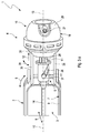
- FIG. 1 comprises a flap device 1, with the aid of which a fluid flow of an internal combustion engine can be controlled, a flap housing 2, at least one flap 3, an adjusting device 4 and a coupling device 5.
- the flap housing 2 encloses in a circumferential direction 6 at least one channel section 7, of the respective Fluid flow in an axial direction 8 can be flowed through.
- the entire fluid flow expediently flows through the channel section 7.
- the flap 3 is pivotable about a pivot axis 10 in the flap housing 2.
- the pivot axis 10 extends transversely, ie perpendicular to the axial direction 8.
- the adjusting device 4 serves to drive the flap 3 and has a linearly adjustable drive shaft 11.
- a linear direction of movement 12 of the drive shaft 11 extends parallel to a longitudinal central axis 13 of the drive shaft 11 which is coaxial with the pivot axis 10, that coincides with this.
- the coupling device 5 has a flap shaft 14 connected in a rotationally fixed manner to the flap 3 and extending coaxially with the pivot axis 10.
- the coupling device 5 couples the flap shaft 14 with the drive shaft 11.
- Flap shaft 14 and drive shaft 11 are aligned coaxially with each other or coaxially to the pivot axis 10.
- the coupling between the flap shaft 14 and the drive shaft 11 by means of the coupling device 5 takes place so that the coupling device 5, the linear movements 12 of the drive shaft 11 in rotational movements 15 of the valve shaft 14 converts.
- the adjusting device 4 is designed as a pressure box 16, which can be controlled hydraulically or pneumatically.
- Fig. 6 an embodiment in which the adjusting device 4 is designed as a temperature-controlled Wachsdehnelement 17.
- the following description refers explicitly only to the variant with the pressure cell 16 as adjusting device 4. It is clear, however, that all features without direct reference to the pressure box 16 in the variant with the Kirdehnelement 17 can be realized as adjusting device 4 and that also features Direct relation to the pressure cell 16 in principle also in the wax expansion element 17 can be realized. Overall, the following description is also implicitly related to the variant with the Wachsdehnelement 17 as adjusting device 4.
- the pressure box 16 comprises a pressure box housing 18, which according to Fig. 5 includes a control room 19. This is limited in the pressure box housing 18 by an elastic membrane 20 which is fixedly connected to the drive shaft 11.
- the pressure box housing 18 also has a control port 21 which is fluidly connected to the control chamber 19. Via the control connection 21, the control chamber 19 can be subjected to an overpressure or a negative pressure, which leads to a corresponding stroke 22 of the membrane 20.
- the hub 22 of the membrane 20 is oriented so that the membrane 20 thereby moves into the control chamber 19 in, that reduces the volume of the control chamber 19. Accordingly, the control chamber 19 is acted upon for adjusting the membrane 20 with a negative pressure.
- a vacuum box 16 In the control chamber 19 is in accordance with Fig. 5
- a return spring 23 is arranged, which drives the membrane 20 from the control chamber 19, ie against the stroke 22.
- the drive shaft 11 is led out of the pressure box housing 18 through a wall section 24 of the pressure box housing 18.
- the wall portion 24 includes a through hole 25 which is penetrated by the drive shaft 11.
- a linear guide 26 is formed, which supports a torque between the drive shaft 11 and pressure box housing 18.
- the linear guide 26 is designed as a double or double tongue and groove guide, in each case a spring 27 engages in a groove 28.
- the two springs 27 are formed on the wall section 24 or on an opening edge enclosing the passage opening 25, while the two grooves 28 are formed on the drive shaft 11 and extend parallel to the longitudinal central axis 13 of the drive shaft 11.
- the two springs 27 are formed on the drive shaft 11, wherein they extend parallel to the longitudinal central axis 13 of the drive shaft 11.
- the associated grooves 28 are in this case formed on the wall section 24 or at the opening edge of the passage opening 25.
- the pressure box housing 18 has a base body 29 and a lid 30 which closes a mounting opening 31 of the base body 29, said mounting opening 31 facing the flap 3.
- the base body 29 contains the control chamber 19 and the return spring 23.
- the membrane 20 forms a separate component with respect to the main body 29 and the lid 30 and is clamped between the main body 29 and the lid 30.
- the membrane 20 is axially clamped or clamped on a retaining edge 32 between corresponding annular steps of the main body 29 and the cover 30, ie parallel to the longitudinal central axis 13 of the drive shaft 11. In this case, the fixation of the membrane 20 on the base body 29 by the fixation of the lid 30 on the base body 29 takes place.
- this may be the base body 29 is latched or clipped to the lid 30.
- Corresponding latching lugs 33 of the cover 30 engage for this purpose in complementary latching openings 34 of the base body 29 a.
- the lid 30 has the wall portion 24 and the passage opening 25.
- the lid 30 is formed integrally on the valve body 2.
- the cover 30 may be connected to the flap housing 2 or to the channel section 7 with the aid of two webs 35 extending parallel to the pivot axis 10.
- the coupling device 5 comprises at least one screw guide 36, in which a bolt 37 engages.
- two such screw guides 36 are provided, which are arranged offset in the circumferential direction 38 of the drive shaft 11 by 180 ° to each other.
- the respective screw guide 36 extends coaxially to the pivot axis 10 helically and is radially open with respect to the pivot axis 10.
- the FIGS. 1 . 4 and 5 show a variant in which the respective screw guide 36 is only radially inwardly open, while it is closed radially on the outside.
- these embodiments show a radial only on one side open screw guide 36.
- 3a to 3c an embodiment in which the respective screw guide 36 is radially inwardly and radially outwardly open, that is designed to be radially continuous.
- the respective screw guide 36 extends helically.
- the two screw guides extend relative to each other in the manner of a double helix.
- the respective pin 37 is rotatably connected to the drive shaft 11, wherein it projects radially outward from the drive shaft 11.
- the respective screw guide 36 is rotatably connected to the flap 3 and is arranged with respect to the drive shaft 11 radially outward. Accordingly, the respective pin 37 engages outwardly into the respective screw guide 36.
- the two bolts 36 are arranged diametrically opposite relative to the longitudinal center axis 13 of the drive shaft 11 and formed by the two longitudinal ends of a single, common pin body 39.
- the drive shaft 11 has a through hole 40 through which the bolt body 39 is passed and is positioned therein so that its longitudinal ends 37 project radially from the drive shaft 11 and thereby form the two bolts 37.
- the coupling device 5 comprises a guide housing 41, which is non-rotatably connected to the valve shaft 14 and which has the screw guides 36.
- the guide housing 41 has on an actuator 4 side facing an insertion opening 42 through which the drive shaft 11 is inserted with the bolts 37 in the guide housing 41, such that in the interior of the guide housing 41 of the respective bolt 37 radially into the associated screw guide 36th intervenes.
- the guide housing 41 is radially open by the consistently designed screw guides 36.
- a cap 43 is also provided, which contains a passage opening 44, through which the drive shaft 11 is passed.
- the cap 43 may include a radial seal 45, which bears against the outer contour of the drive shaft 11.
- the outer contour of the drive shaft 11 is in an axial portion of the drive shaft 11, which is moved relative to the cap 43 in the context of the linear adjustment 12 of the drive shaft 11, cylindrical, preferably circular cylindrical, thereby simplifying the seal.
- Fig. 3a is the pressure cell 18 in an initial position.
- the return spring 23 presses the membrane 20 into the cover 30 into a first end position.
- the membrane 20 can be moved in the direction of the main body 29, whereby it performs a stroke 22.
- the membrane 20 takes the drive shaft 11, whereby the drive shaft 11 performs its linear movement 12.
- Fig. 3b is an intermediate position of the pressure cell 16 reproduced, in which the drive shaft 11 has performed about half a stroke. Since the drive shaft 11 is rotatably supported on the pressure box housing 18 via the linear guide 26, the screws 37 engaging in the screw guides 36 force a rotation of the guide housing 41. Since the guide housing 41 is non-rotatably connected with the flap shaft 14 and this is rotationally fixed to the flap 3 a corresponding rotational adjustment of the flap 3 about the pivot axis 10th
- Fig. 3c the membrane 20 is maximally adjusted into the main body 29, so that it reaches its second end position.
- the drive shaft 11 has now reached its maximum travel.
- the flap 3 is maximally adjusted in this final state.
- Fig. 3a In the initial state according to Fig. 3a is the flap 3 in a closed position in which it obstructs the flow-through cross section 9 of the channel section 7.
- the flap 3 In the end position according to Fig. 3c the flap 3 is pivoted by 90 ° relative to the starting position, so that it releases the flow-through cross-section 9.
- the intermediate position according to Fig. 3b is the flap 3, for example, pivoted about 45 ° relative to the starting position.
- the respective screw guide 36 In order to achieve such a 90 ° pivoting of the flap 3, the respective screw guide 36 extends in the circumferential direction over approximately 90 °, whereby at maximum stroke of the drive shaft 11 and the membrane 20 a quarter turn of the flap 3 is achieved.
- the flow-through cross-section 9 of the channel section 7 according to a preferred embodiment in a parallel to the pivot axis 10 extending width direction 46 dimensioned larger than in a transverse thereto height direction 47.
- the orientalströmbare cross-section 9 about five to six times wider than high.
- the flow-through cross-section 9 in the width direction 46 tapers with increasing distance from the adjusting device 4.
- the rejuvenation is continuously designed here. For example, the height of the flow-through cross-section 9 decreases over the entire width by about 25%.
- the flap 3 is designed here as a butterfly flap, which is shaped in terms of their contour complementary to the geometry of the flow-through cross-section 9.
- the valve shaft 14 has distal and proximal to the adjusting device 4 each have a bearing portion 48, which preferably has a circular-cylindrical outer contour.
- the respective bearing section 48 is inserted into a bearing region 49 of the housing 2 or the channel section 7 parallel to the axial direction 8.
- the flap 3 is made with its flap shaft 14 and the guide housing 41 integrally from one piece.
Landscapes
- Engineering & Computer Science (AREA)
- General Engineering & Computer Science (AREA)
- Mechanical Engineering (AREA)
- Chemical & Material Sciences (AREA)
- Combustion & Propulsion (AREA)
- Lift Valve (AREA)
Abstract
Description
- Die vorliegende Erfindung betrifft eine Klappeneinrichtung zum Steuern einer Fluidströmung einer Brennkraftmaschine, mit den Merkmalen des Oberbegriffs des Anspruchs 1.
- Aus der
DE 10 2007 003 317 A1 ist eine Klappeneinrichtung bekannt, bei der ein Klappengehäuse einen von einer Abgasströmung in einer Axialrichtung durchströmbaren Kanalabschnitt in einer Umfangsrichtung umschließt. Zum Steuern eines durchströmbaren Querschnitts des Kanalabschnitts ist im Klappengehäuse eine Klappe um eine quer zur Axialrichtung verlaufende Schwenkachse verschwenkbar angeordnet. Eine Stelleinrichtung zum Antreiben der Klappe weist eine linear verstellbare Antriebswelle auf, wobei eine Kopplungseinrichtung vorgesehen ist, die eine drehfest mit der Klappe verbundene, koaxial zur Schwenkachse verlaufende Klappenwelle mit der koaxial zur Schwenkachse ausgerichteten Antriebswelle koppelt, derart, dass sie lineare Bewegungen der Antriebswelle in Drehbewegungen der Klappenwelle umwandelt. Die bekannte Klappeneinrichtung arbeitet dabei mit einem elektromotorischen Antrieb zum linearen Verstellen der Antriebswelle. - Ein Linear-Schrittmotor mit axial bewegbarer Antriebswelle ist beispielsweise aus der
DE 199 41 309 A1 bekannt. - Aus der
DE 100 15 978 A1 ist eine weitere Klappeneinrichtung bekannt, bei der ein Rotationsmotor verwendet wird, um eine Antriebswelle drehend anzutreiben. Dabei ist die Antriebswelle als Spindel konfiguriert, auf die eine Mutter aufgesetzt ist, die einen davon radial abstehenden Zapfen trägt. Die Mutter ist in einer stehenden Axialführung drehfest gehalten, so dass eine Rotation der Spindel eine Axialbewegung der Mutter entlang der Spindel bewirkt. Der Zapfen steht dabei mit einer Kulisse in Eingriff, die an einer Klappenwelle ausgebildet ist. Die Kulisse ist dabei schraubenförmig geformt, so dass eine Axialverstellung des Zapfens zu einer Rotation der mit der Klappenwelle verbundenen Klappe führt, wobei die Klappe koaxial zur Drehachse der Spindel schwenkt. - Die vorliegende Erfindung beschäftigt sich mit dem Problem, für eine Klappeneinrichtung der eingangs genannten Art eine verbesserte oder zumindest eine andere Ausführungsform anzugeben, die sich insbesondere durch einen preiswerten Aufbau auszeichnet. Gleichzeitig ist angestrebt, die Klappeneinrichtung so zu konfigurieren, dass eine Baugruppe, welche mit einer derartigen Klappeneinrichtung ausgestattet ist, einfach vormontierbar und einfach in die zugehörige Peripherie der Brennkraftmaschine eingebaut werden kann.
- Dieses Problem wird erfindungsgemäß durch den Gegenstand des unabhängigen Anspruchs gelöst. Vorteilhafte Ausführungsformen sind Gegenstand der abhängigen Ansprüche.
- Die Erfindung beruht auf dem allgemeinen Gedanken, die Stelleinrichtung als hydraulisch oder pneumatisch ansteuerbare Druckdose oder als temperaturgesteuertes Wachsdehnelement auszugestalten. Sowohl eine Druckdose als auch ein Wachsdehnelement arbeiten ohne elektrische Energieversorgung, was den Aufwand zur Realisierung der Klappeneinrichtung reduziert. Ebenso vereinfacht sich die Montage einer damit ausgestatteten Baugruppe an der Brennkraftmaschine, da keine elektrischen Kontakte verlegt und hergestellt werden müssen. Des weiteren arbeiten Druckdosen sehr zuverlässig. Auch ist die Versorgung mit dem erforderlichen Steuerdruck relativ einfach realisierbar, da im Bereich einer Brennkraftmaschine unterschiedlichste hydraulische oder pneumatische Systeme zur Verfügung stehen, die zur Bereitstellung des gewünschten Steuerdrucks genutzt werden können.
- Die Verwendung eines Wachsdehnelements ermöglicht eine einfache, zuverlässige Temperatursteuerung der Klappe.
- Entsprechend einer vorteilhaften Ausführungsform der Klappeneinrichtung, bei welcher die Stelleinrichtung als Druckdose ausgestaltet ist, kann die Druckdose in einem Druckdosengehäuse einen Steuerraum aufweisen, der durch eine elastische Membran begrenzt ist, die fest mit der Antriebswelle verbunden ist, wobei das Druckdosengehäuse einen mit dem Steuerraum fluidisch verbundenen Steueranschluss aufweist, über den der Steuerraum zum Verstellen der Membran mit einem Überdruck oder mit einem Unterdruck beaufschlagbar ist. Hierdurch besitzt die Druckdose einen besonders einfachen, leicht herstellbaren Aufbau, der sich durch eine zuverlässige Funktionsweise auszeichnet. Je nach dem, ob zum Ansteuern der Membran ein Überdruck oder ein Unterdruck im Steuerraum erzeugt wird, handelt es sich bei der verwendeten Druckdose entweder um eine Unterdruckdose oder um eine Überdruckdose.
- Gemäß einer vorteilhaften Weiterbildung kann in der Druckdose eine mit der Membran zusammenwirkende Rückstellfeder oder Vorspannfeder vorgesehen sein, mit der die Membran in eine erste Endstellung vorgespannt ist. Ohne Druckbeaufschlagung des Steuerraums nimmt die Membran dann diese erste Endstellung selbsttätig ein. Durch die Druckbeaufschlagung des Steuerraums kann die Membran aus der ersten Endstellung entgegen der Federkraft der Rückstell- oder Vorspannfeder verstellt werden, maximal bis in eine zweite Endstellung.
- Bei einer anderen vorteilhaften Weiterbildung kann die Antriebswelle durch einen Wandabschnitt des Druckdosengehäuses aus dem Druckdosengehäuse herausgeführt sein, wobei zwischen der Antriebswelle und dem Wandabschnitt eine Drehmoment abstützende Linearführung ausgebildet ist. Mit anderen Worten, zwischen der mit der Membran verbundenen Antriebswelle und dem Druckdosengehäuse erfolgt eine Drehmomentabstützung mittels einer Linearführung. Hierdurch wird erreicht, dass die Antriebswelle, die durch die Hubbewegungen der Membran linear angetrieben ist, keine Rotationsbewegung um ihre Längsmittelachse durchführen kann, die sich koaxial zur Schwenkachse der Klappe erstreckt. Drehmomente, welche die Antriebswelle drehend antreiben, entstehen in der Antriebswelle als Reaktion zu den Drehmomenten, die innerhalb der Kopplungseinrichtung beim Umwandeln der linearen Bewegung der Antriebswelle in eine Drehbewegung der Klappenwelle quasi als Aktion entstehen. Durch die Drehmomentabstützung der Antriebswelle am Druckdosengehäuse ist die Membran völlig von Drehmomenten entlastet, so dass in der Druckdose eine herkömmliche Membran mit herkömmlicher Anbindung zur Antriebswelle verwendet werden kann.
- Die Linearführung kann beispielsweise mit wenigstens einer Nut-Feder-Führung realisiert sein. Eine derartige Nut-Feder-Führung lässt sich dabei einfach oder zweifach oder mehrfach realisieren, um das Drehmoment der Antriebswelle in der Umfangsrichtung an einer Stelle oder an zwei Stellen oder an mehreren Stellen am Druckdosengehäuse abzustützen. Dabei kann die jeweilige Nut in der Antriebswelle ausgebildet sein, so dass die darin eingreifende Feder dann am Druckdosengehäuse angeordnet ist. Ebenso ist es möglich, die Feder an der Antriebswelle auszubilden und die zugehörige Nut am Druckdosengehäuse vorzusehen. Letztere Variante scheint im Hinblick auf die Möglichkeit, größere Drehmomente abzustützen, vorteilhaft zu sein. Die Drehmoment abstützende Kontur des Druckdosengehäuses, also insbesondere die jeweilige Nut oder die jeweilige Feder, kann dabei vorzugsweise unmittelbar an einem Öffnungsrand ausgeformt sein, der eine Durchgangsöffnung in der Umfangsrichtung einfasst, durch welche die Antriebswelle aus dem Druckdosengehäuse herausgeführt ist.
- Andere Linearführungen, die eine Drehmomentabstützung bewirken, lassen sich beispielsweise mittels einer im Querschnitt mehrkantigen Außenkontur der Antriebswelle realisieren, die mit einer dazu komplementären, mehrkantigen Innenkontur an vorstehend genanntem Öffnungsrand zusammenwirkt.
- Bei einer anderen vorteilhaften Weiterbildung kann das Druckdosengehäuse einen Grundkörper und einen Deckel aufweisen, der eine der Klappe zugewandte Montageöffnung des Grundkörpers verschließt. Hierdurch ergibt sich ein einfacher Aufbau für die Druckdose, was deren Herstellung preiswert macht. Vorzugsweise enthält der Grundkörper den Steuerraum. Ferner weist der Grundkörper bevorzugt den Steueranschluss auf. Die Membran ist zweckmäßig zwischen dem Grundkörper und dem Deckel geklemmt, so dass die Membran durch das Anbringen des Deckels am Grundkörper fixiert wird. Der Deckel weist dagegen den Wandabschnitt des Druckdosengehäuses auf, der die von der Antriebswelle durchsetzte Durchgangsöffnung enthält. Zweckmäßig können der Grundkörper und der Deckel miteinander verclipst sein. Wodurch beispielsweise eine werkzeugfreie Montage ermöglicht wird.
- Gemäß einer besonders vorteilhaften Weiterbildung kann der Deckel integral am Klappengehäuse ausgeformt sein. Auf diese Weise wird die Druckdose durch das Anbringen des Grundkörpers mit eingesetzter Membran am Deckel bzw. am Klappengehäuse vervollständigt. Insgesamt lässt sich dadurch die Klappeneinrichtung besonders einfach realisieren. Beispielsweise können zusätzliche Befestigungsmaßnahmen und Befestigungselemente entfallen, mit denen die Druckdose am Klappengehäuse befestigt werden muss.
- Bei einer anderen vorteilhaften Ausführungsform kann die Kopplungseinrichtung wenigstens eine sich koaxial zur Schwenkachse schraubenförmig erstreckende, radial offene Schraubenführung aufweisen, in die ein Bolzen radial eingreift. Eine derartige helixartige Schraubenführung erzwingt bei einer Linearverstellung zwischen Bolzen und Schraubenführung eine Drehverstellung zwischen Bolzen und Schraubenführung. Die Schraubenführung und zugehöriger Bolzen können beispielsweise so angeordnet sein, dass der Bolzen radial nach außen oder radial nach innen in die Schraubenführung eingreift. Ferner kann vorgesehen sein, die Schraubenführung bezüglich der Klappenwelle oder bezüglich der Antriebswelle drehfest anzuordnen, wobei dann der zugehörige Bolzen entweder bezüglich der Antriebswelle oder bezüglich der Klappenwelle drehfest angeordnet ist.
- Die Kopplungseinrichtung kann dabei entweder nur eine einzige helixartige Schraubenführung oder mehrere, koaxial zueinander angeordnete, axial ineinandergreifende helixartige Schraubenführungen aufweisen. Besonders zweckmäßig ist dabei eine Konfiguration, bei welcher genau zwei helixartige Schraubenführungen vorgesehen sind, die in der Umfangsrichtung um 180° zueinander versetzt angeordnet sind. Demnach sind die beiden Schraubenführungen quasi nach Art einer Doppelhelix angeordnet. Hierdurch ergibt sich eine in der Umfangsrichtung verteilte, vorzugsweise symmetrische Drehmomentabstützung innerhalb der Kopplungseinrichtung zwischen den Bolzen und den zugehörigen Schraubenführungen.
- Bei einer anderen vorteilhaften Weiterbildung kann der Bolzen drehfest mit der Antriebswelle verbunden sein und radial nach außen in die jeweilige Schraubenführung eingreifen, die drehfest mit der Klappenwelle verbunden ist. Eine derartige Bauform ist besonders einfach realisierbar.
- Der jeweilige Bolzen kann in Form eines separaten Bauteils an die Antriebswelle angebaut sein. Beispielsweise kann die Antriebswelle hierzu eine Bolzenöffnung aufweisen, in die der jeweilige Bolzen eingesteckt ist. Zur Realisierung von zwei diametral angeordneten, jeweils nach außen abstehenden Bolzen, die mit zwei Schraubenführungen zusammenwirken, kann ein einziger Bolzenkörper verwendet werden, der in eine die Antriebswelle durchdringende Bolzenöffnung so eingesetzt ist, dass er mit seinen Längsenden die beiden von der Antriebswelle abstehenden Bolzen bildet.
- Gemäß einer anderen vorteilhaften Ausführungsform kann die jeweilige Schraubenführung integral an der Klappenwelle ausgeformt sein, wodurch sich der Zusammenbau der Klappeneinrichtung vereinfacht.
- Gemäß einer anderen vorteilhaften Weiterbildung kann die Kopplungseinrichtung ein Führungsgehäuse aufweisen, das drehfest mit der Klappenwelle verbunden ist, das die wenigstens eine Schraubenführung aufweist und das an einer der Stelleinrichtung zugewandten Seite eine Einführöffnung aufweist, durch welche die Antriebswelle mit dem jeweiligen Bolzen in das Führungsgehäuse eingeführt ist. Auch diese Maßnahme führt zu einem einfach realisierbaren Aufbau. Insbesondere kann das Führungsgehäuse integral an der Klappenwelle ausgeformt sein.
- Bei einer Weiterbildung kann das Führungsgehäuse abgesehen von der Einführöffnung nach außen geschlossen ausgestaltet sein, wobei die Einführöffnung mit einer Kappe verschlossen ist, die eine Durchgangsöffnung enthält, durch welche die Antriebswelle hindurchgeführt ist. Somit lässt sich ein Innenraum des Führungsgehäuses nach außen hermetisch verschließen, beispielsweise um eine Verschmutzung der jeweiligen Schraubenführung zu verhindern.
- Gemäß einer zweckmäßigen Weiterbildung kann die Kappe im Bereich der Durchgangsöffnung eine Radialdichtung aufweisen, die außen an der Antriebswelle anliegt. Hierdurch kann die Abdichtung des Innenraums des Führungsgehäuses zusätzlich verbessert werden. Die Antriebswelle kann gemäß einer bevorzugten Bauform zumindest in einem Längsabschnitt, der sich im Betrieb der Klappeneinrichtung, also bei der Linearverstellung der Antriebswelle, innerhalb der Durchgangsöffnung relativ zum Führungsgehäuse bewegt, mit einem kreiszylindrischen Querschnitt ausgestattet sein. Hierdurch lässt sich die Abdichtung der Durchgangsöffnung mit Hilfe einer Radialdichtung signifikant verbessern.
- Bei einer anderen vorteilhaften Ausführungsform kann der durchströmbare Querschnitt des Kanalabschnitts in einer parallel zur Schwenkachse verlaufenden Breitenrichtung mindestens zweimal oder mindestens dreimal, vorzugsweise vieroder fünfmal, größer sein als in einer quer dazu verlaufenden Höhenrichtung. Der durchströmbare Querschnitt des Kanalabschnitts wird dadurch flach, wodurch sich für die Klappeneinrichtung eine kompakte Bauform realisieren lässt.
- Zusätzlich oder alternativ kann vorgesehen sein, dass sich der durchströmbare Querschnitt des Kanalabschnitts in einer parallel zur Schwenkachse verlaufenden Breitenrichtung mit zunehmendem Abstand von der Stelleinrichtung verjüngt. Hierdurch wird für den Kanalabschnitt eine spezielle Geometrie geschaffen, die für bestimmte Anwendungsformen vorteilhaft sein kann. Die Verjüngung des durchströmbaren Querschnitts erfolgt zweckmäßig kontinuierlich.
- Die Klappe ist zweckmäßig komplementär zum durchströmbaren Querschnitt geformt, um den Querschnitt in einer Schließstellung möglichst weitgehend verschließen zu können.
- Gemäß einer vorteilhaften Ausführungsform erstreckt sich die Schwenkachse im Wesentlichen mittig zum durchströmbaren Querschnitt, wobei sich die Klappe dann beiderseits der Schwenkachse erstreckt, wodurch die Klappe quasi als Schmetterlingsklappe konfiguriert ist.
- Bei einer anderen Ausführungsform kann die Klappenwelle proximal zur Stellein.richtung und distal zur Stelleinrichtung jeweils einen Lagerabschnitt aufweisen, der in einem Lagerbereich des Gehäuses bzw. des Kanalabschnitts parallel zur Axialrichtung eingesetzt ist. Auch diese Maßnahme führt zu einer vereinfachten Herstellung der Klappeneinrichtung.
- Die Klappe ist vorzugsweise integral an der Klappenwelle ausgeformt, wodurch auch hier eine einfache Realisierbarkeit erzielt werden kann.
- Eine bevorzugte Anwendung der Klappeneinrichtung wird in einer Frischluftanlage gesehen, beispielsweise als Drosselklappeneinrichtung. Eine derartige frischluftseitige Anordnung der Klappeneinrichtung hat den Vorteil, dass viele Komponenten aus einem Kunststoff hergestellt werden können. Beispielsweise können das Klappengehäuse, die Klappe und das Druckdosengehäuse aus Kunststoff hergestellt werden. Zusätzlich können auch die Klappenwelle und die Antriebswelle aus Kunststoff hergestellt werden. Schließlich lässt sich außerdem die Kopplungseinrichtung aus Kunststoff preiswert herstellen.
- Gemäß einer vorteilhaften Ausführungsform kann die Kopplungseinrichtung außerhalb eines Gehäuses der Stelleinrichtung angeordnet sein. Hierdurch ist es möglich, quasi beliebige bekannte Stelleinrichtungen zu verwenden, so dass auf preiswerte, in der praxis bewährte Ausführungsformen von Stelleinrichtungen zurückgegriffen werden kann. Hierdurch gestaltet sich die Klappeneinrichtung vergleichsweise preiswert.
- Besonders vorteilhaft ist eine Ausführungsform, bei der die Kopplungseinrichtung axial zwischen einem Gehäuse der Stelleinrichtung und dem Klappengehäuse angeordnet ist. Hierdurch ergibt sich eine sehr schlanke und einfach montierbare Bauform.
- Gemäß einer weiteren Ausführungsform kann die Kopplungseinrichtung ein separates oder eigenes Gehäuse aufweist, das mit der Klappenwelle drehfest verbunden ist. Hierdurch lässt sich die Kopplungseinrichtung beispielsweise einfach gegen Verschmutzung schützen. Das Gehäuse der Kopplungseinrichtung ist dabei insbesondere zusätzlich und separat zum Klappengehäuse und/oder zu einem Gehäuse der Stelleinrichtung vorgesehen.
- Weitere wichtige Merkmale und Vorteile der Erfindung ergeben sich aus den Unteransprüchen, aus den Zeichnungen und aus der zugehörigen Figurenbeschreibung anhand der Zeichnungen.
- Es versteht sich, dass die vorstehend genannten und die nachstehend noch zu erläuternden Merkmale nicht nur in der jeweils angegebenen Kombination, sondern auch in anderen Kombinationen oder in Alleinstellung verwendbar sind, ohne den Rahmen der vorliegenden Erfindung zu verlassen.
- Bevorzugte Ausführungsbeispiele der Erfindung sind in den Zeichnungen dargestellt und werden in der nachfolgenden Beschreibung näher erläutert, wobei sich gleiche Bezugszeichen auf gleiche oder ähnliche oder funktional gleiche Komponenten beziehen.
- Es zeigen, jeweils schematisch
- Fig. 1
- eine isometrische Ansicht einer Klappeneinrichtung,
- Fig. 2
- eine isometrische Ansicht einer Stelleinrichtung,
- Fig. 3
- isometrische Ansichten der Klappeneinrichtung im Bereich der Stelleinrichtung bei verschiedenen Betriebszuständen a, b und c,
- Fig. 4
- eine isometrische Ansicht der Klappeneinrichtung im Bereich der Stelleinrichtung, bei einer anderen Ausführungsform,
- Fig. 5
- eine isometrische, auseinandergezogene Darstellung der Klappeneinrichtung aus
Fig. 4 , - Fig. 6
- eine isometrische Ansicht der Stelleinrichtung bei einer weiteren Ausführungsform.
- Entsprechend
Fig. 1 umfasst eine Klappeneinrichtung 1, mit deren Hilfe eine Fluidströmung einer Brennkraftmaschine gesteuert werden kann, ein Klappengehäuse 2, zumindest eine Klappe 3, eine Stelleinrichtung 4 und eine Kopplungseinrichtung 5. Das Klappengehäuse 2 umschließt in einer Umfangsrichtung 6 zumindest einen Kanalabschnitt 7, der von der jeweiligen Fluidströmung in einer Axialrichtung 8 durchströmbar ist. Zweckmäßig strömt dabei die gesamte Fluidströmung durch den Kanalabschnitt 7. Die Klappe 3 ist zum Steuern eines durchströmbaren Querschnitts 9 des Kanalabschnitts 7 um eine Schwenkachse 10 im Klappengehäuse 2 verschwenkbar angeordnet. Die Schwenkachse 10 erstreckt sich dabei quer, also senkrecht zur Axialrichtung 8. Die Stelleinrichtung 4 dient zum Antreiben der Klappe 3 und weist eine linear verstellbare Antriebswelle 11 auf. Eine lineare Bewegungsrichtung 12 der Antriebswelle 11 verläuft dabei parallel zu einer Längsmittelachse 13 der Antriebswelle 11, die koaxial zur Schwenkachse 10 verläuft, also mit dieser zusammenfällt. - Die Kopplungseinrichtung 5 weist eine drehfest mit der Klappe 3 verbundene Klappenwelle 14 auf, die sich koaxial zur Schwenkachse 10 erstreckt. Die Kopplungseinrichtung 5 koppelt die Klappenwelle 14 mit der Antriebswelle 11. Klappenwelle 14 und Antriebswelle 11 sind dabei koaxial zueinander bzw. koaxial zur Schwenkachse 10 ausgerichtet. Die Kopplung zwischen der Klappenwelle 14 und der Antriebswelle 11 mit Hilfe der Kopplungseinrichtung 5 erfolgt dabei so, dass die Kopplungseinrichtung 5 die linearen Bewegungen 12 der Antriebswelle 11 in Drehbewegungen 15 der Klappenwelle 14 umwandelt.
- Bei den Ausführungsformen der
Figuren 1 bis 5 ist die Stelleinrichtung 4 als Druckdose 16 ausgestaltet, die hydraulisch oder pneumatisch angesteuert werden kann. Im Unterschied dazu zeigtFig. 6 eine Ausführungsform, bei welcher die Stelleinrichtung 4 als temperaturgesteuertes Wachsdehnelement 17 ausgestaltet ist. Die nachfolgende Beschreibung bezieht sich explizit nur auf die Variante mit der Druckdose 16 als Stelleinrichtung 4. Es ist jedoch klar, dass alle Merkmale ohne direkten Bezug zur Druckdose 16 auch bei der Variante mit dem Wechseldehnelement 17 als Stelleinrichtung 4 realisierbar sind und dass auch Merkmale mit direktem Bezug zur Druckdose 16 grundsätzlich auch beim Wachsdehnelement 17 realisierbar sind. Insgesamt ist die nachfolgende Beschreibung auch implizit auf die Variante mit dem Wachsdehnelement 17 als Stelleinrichtung 4 bezogen. - Entsprechend den
Figuren 1 bis 5 umfasst die Druckdose 16 ein Druckdosengehäuse 18, das gemäßFig. 5 einen Steuerraum 19 enthält. Dieser ist im Druckdosengehäuse 18 durch eine elastische Membran 20 begrenzt, die mit der Antriebswelle 11 fest verbunden ist. Das Druckdosengehäuse 18 weist außerdem einen Steueranschluss 21 auf, der mit dem Steuerraum 19 fluidisch verbunden ist. Über den Steueranschluss 21 kann der Steuerraum 19 mit einem Überdruck oder mit einem Unterdruck beaufschlagt werden, was zu einem entsprechenden Hub 22 der Membran 20 führt. GemäßFig. 5 ist der Hub 22 der Membran 20 so orientiert, dass sich die Membran 20 dabei in den Steuerraum 19 hinein bewegt, also das Volumen des Steuerraums 19 reduziert. Dementsprechend wird der Steuerraum 19 zum Verstellen der Membran 20 mit einem Unterdruck beaufschlagt. Dementsprechend handelt es sich bei der hier gezeigten, bevorzugten Ausführungsform um eine Unterdruckdose 16. Im Steuerraum 19 ist gemäßFig. 5 außerdem eine Rückstellfeder 23 angeordnet, welche die Membran 20 aus dem Steuerraum 19, also entgegen dem Hub 22, antreibt. - Gemäß den
Figuren 2 und4 ist die Antriebswelle 11 durch einen Wandabschnitt 24 des Druckdosengehäuses 18 aus dem Druckdosengehäuse 18 herausgeführt. Hierzu enthält der Wandabschnitt 24 eine Durchgangsöffnung 25, die von der Antriebswelle 11 durchsetzt ist. Zwischen der Antriebswelle 11 und dem Wandabschnitt 24 ist eine Linearführung 26 ausgebildet, die ein Drehmoment zwischen Antriebswelle 11 und Druckdosengehäuse 18 abstützt. Bei den hier gezeigten Beispielen ist die Linearführung 26 als doppelte bzw. zweifache Nut-Feder-Führung konzipiert, bei der jeweils eine Feder 27 in eine Nut 28 eingreift. Bei der inFig. 2 gezeigten Ausführungsform sind die beiden Federn 27 am Wandabschnitt 24 bzw. an einem die Durchgangsöffnung 25 einfassenden Öffnungsrand ausgebildet, während die beiden Nuten 28 an der Antriebswelle 11 ausgebildet sind und sich parallel zur Längsmittelachse 13 der Antriebswelle 11 erstrecken. Bei der inFig. 4 gezeigten Ausführungsform sind dagegen die beiden Federn 27 an der Antriebswelle 11 ausgeformt, wobei sie sich parallel zur Längsmittelachse 13 der Antriebswelle 11 erstrecken. Die zugehörigen Nuten 28 sind hierbei am Wandabschnitt 24 bzw. am Öffnungsrand der Durchgangsöffnung 25 ausgebildet. - Bei den hier gezeigten Ausführungsformen besitzt das Druckdosengehäuse 18 einen Grundkörper 29 und einen Deckel 30, der eine Montageöffnung 31 des Grundkörpers 29 verschließt, wobei diese Montageöffnung 31 der Klappe 3 zugewandt ist. Zweckmäßig enthält der Grundkörper 29 den Steuerraum 19 und die Rückstellfeder 23. Die Membran 20 bildet bezüglich des Grundkörpers 29 und des Deckels 30 ein separates Bauteil und ist zwischen dem Grundkörper 29 und dem Deckel 30 eingeklemmt. Zweckmäßig wird die Membran 20 an einem Halterand 32 zwischen entsprechenden Ringstufen des Grundkörpers 29 und des Deckels 30 axial, also parallel zur Längsmittelachse 13 der Antriebswelle 11 geklemmt bzw. verspannt. Dabei erfolgt die Fixierung der Membran 20 am Grundkörper 29 durch die Fixierung des Deckels 30 am Grundkörper 29. Beispielsweise kann hierzu der Grundkörper 29 mit dem Deckel 30 verrastet oder verclipst sein. Entsprechende Rastnasen 33 des Deckels 30 greifen hierzu in dazu komplementäre Rastöffnungen 34 des Grundkörpers 29 ein. Der Deckel 30 weist den Wandabschnitt 24 und die Durchgangsöffnung 25 auf. Gemäß den bevorzugten Ausführungsformen der
Figuren 1 und3 bis 5 ist der Deckel 30 integral am Klappengehäuse 2 ausgeformt. Beispielsweise kann der Deckel 30 hierzu mit Hilfe von zwei parallel zur Schwenkachse 10 verlaufenden Stegen 35 mit dem Klappengehäuse 2 bzw. mit dem Kanalabschnitt 7 verbunden sein. - Gemäß den
Figuren 1 und3 bis 5 umfasst die Kopplungseinrichtung 5 zumindest eine Schraubenführung 36, in die ein Bolzen 37 eingreift. Bei den hier gezeigten Ausführungsformen sind zwei derartige Schraubenführungen 36 vorgesehen, die in der Umfangsrichtung 38 der Antriebswelle 11 um 180° zueinander versetzt angeordnet sind. Die jeweilige Schraubenführung 36 erstreckt sich dabei koaxial zur Schwenkachse 10 schraubenförmig und ist dabei bezüglich der Schwenkachse 10 radial offen. DieFiguren 1 ,4 und5 zeigen dabei eine Variante, bei welcher die jeweilige Schraubenführung 36 nur radial innen offen ist, während sie radial außen geschlossen ist. Also zeigen diese Ausführungsformen eine nur einseitig radial offene Schraubenführung 36. Im Unterschied dazu zeigen dieFiguren 3a bis 3c eine Ausführungsform, bei welcher die jeweilige Schraubenführung 36 radial nach innen und radial nach außen offen ist, also radial durchgängig konzipiert ist. Die jeweilige Schraubenführung 36 erstreckt sich helixartig. Die beiden Schraubenführungen erstrecken sich relativ zueinander nach Art einer Doppelhelix. - Bei den hier gezeigten Ausführungsformen ist der jeweilige Bolzen 37 drehfest mit der Antriebswelle 11 verbunden, wobei er von der Antriebswelle 11 radial nach außen absteht. Die jeweilige Schraubenführung 36 ist drehfest mit der Klappe 3 verbunden und ist bezüglich der Antriebswelle 11 radial außen angeordnet. Dementsprechend greift der jeweilige Bolzen 37 nach außen in die jeweilige Schraubenführung 36 ein. Bei den hier gezeigten Ausführungsformen sind die beiden Bolzen 36 bezüglich der Längsmittelachse 13 der Antriebswelle 11 diametral gegenüberliegend angeordnet und durch die beiden Längsenden eines einzigen, gemeinsamen Bolzenkörpers 39 gebildet. Zur Aufnahme des Bolzenkörpers 39 besitzt die Antriebswelle 11 eine Durchgangsöffnung 40, durch die der Bolzenkörper 39 hindurchgeführt ist und darin so positioniert ist, dass seine Längsenden 37 radial von der Antriebswelle 11 abstehen und dadurch die beiden Bolzen 37 bilden.
- Bei den hier gezeigten Ausführungsformen umfasst die Kopplungseinrichtung 5 ein Führungsgehäuse 41, das drehfest mit der Klappenwelle 14 verbunden ist und das die Schraubenführungen 36 aufweist. Das Führungsgehäuse 41 weist an einer der Stelleinrichtung 4 zugewandten Seite eine Einführöffnung 42 auf, durch welche die Antriebswelle 11 mit den Bolzen 37 in das Führungsgehäuse 41 eingeführt ist, derart, dass im Inneren des Führungsgehäuses 41 der jeweilige Bolzen 37 radial in die zugehörige Schraubenführung 36 eingreift.
- Bei der in den
Figuren 3a bis 3c gezeigten Ausführungsform ist das Führungsgehäuse 41 durch die durchgängig konzipierten Schraubenführungen 36 radial offen. Im Unterschied dazu ist das Führungsgehäuse 41 bei den Ausführungsformen derFiguren 1 ,4 und5 abgesehen von der Einführöffnung 42 nach außen verschlossen. Zum Verschließen der Einführöffnung 42 ist außerdem eine Kappe 43 vorgesehen, die eine Durchgangsöffnung 44 enthält, durch welche die Antriebswelle 11 hindurchgeführt ist. Im Bereich dieser Durchgangsöffnung 44 kann die Kappe 43 eine Radialdichtung 45 enthalten, die an der Außenkontur der Antriebswelle 11 anliegt. Die Außenkontur der Antriebswelle 11 ist in einem Axialabschnitt der Antriebswelle 11, der im Rahmen der Linearverstellungen 12 der Antriebswelle 11 relativ zur Kappe 43 bewegt wird, zylindrisch, vorzugsweise kreiszylindrisch konzipiert, wodurch sich die Abdichtung vereinfacht. - Die Funktion der Kopplungseinrichtung 5 wird mit Bezug auf die
Figuren 3a bis 3c näher erläutert. InFig. 3a befindet sich die Druckdose 18 in einer Ausgangsstellung. In dieser Ausgangsstellung drückt die Rückstellfeder 23 die Membran 20 in den Deckel 30 hinein in eine erste Endstellung. Durch Anlegen eines Unterdrucks über den Steueranschluss 21 an den Steuerraum 19 kann die Membran 20 in Richtung Grundkörper 29 bewegt werden, wodurch sie einen Hub 22 durchführt. Hierbei nimmt die Membran 20 die Antriebswelle 11 mit, wodurch die Antriebswelle 11 ihre lineare Bewegung 12 durchführt. - In
Fig. 3b ist eine Zwischenstellung der Druckdose 16 wiedergegeben, in der die Antriebswelle 11 etwa einen halben Hub durchgeführt hat. Da die Antriebswelle 11 über die Linearführung 26 drehfest am Druckdosengehäuse 18 abgestützt ist, erzwingen die in die Schraubenführungen 36 eingreifenden Bolzen 37 eine Rotation des Führungsgehäuses 41. Da das Führungsgehäuse 41 drehfest mit der Klappenwelle 14 und diese drehfest mit der Klappe 3 verbunden ist, ergibt sich eine entsprechende Drehverstellung der Klappe 3 um die Schwenkachse 10. - In
Fig. 3c ist die Membran 20 maximal in den Grundkörper 29 hinein verstellt, so dass sie ihre zweite Endstellung erreicht. Auch die Antriebswelle 11 hat nun ihren maximalen Stellweg erreicht. Somit ist auch die Klappe 3 in diesem Endzustand maximal verstellt. - Im Ausgangszustand gemäß
Fig. 3a ist die Klappe 3 in einer Schließstellung, in der sie den durchströmbaren Querschnitt 9 des Kanalabschnitts 7 versperrt. In der Endstellung gemäßFig. 3c ist die Klappe 3 gegenüber der Ausgangsstellung um 90° verschwenkt, so dass sie den durchströmbaren Querschnitt 9 frei gibt. In der Zwischenstellung gemäßFig. 3b ist die Klappe 3 beispielsweise um etwa 45° gegenüber der Ausgangsstellung verschwenkt. Um eine derartige 90°-Verschwenkung der Klappe 3 zu erzielen, erstreckt sich die jeweilige Schraubenführung 36 in der Umfangsrichtung über etwa 90°, wodurch bei maximalem Hub der Antriebswelle 11 bzw. der Membran 20 eine Vierteldrehung der Klappe 3 erreicht wird. - Wie sich insbesondere
Fig. 1 entnehmen lässt, ist der durchströmbare Querschnitt 9 des Kanalabschnitts 7 gemäß einer bevorzugten Ausführungsform in einer parallel zur Schwenkachse 10 verlaufenden Breitenrichtung 46 größer dimensioniert als in einer quer dazu verlaufenden Höhenrichtung 47. Im Beispiel derFig. 1 ist der durchströmbare Querschnitt 9 etwa fünf- bis sechsmal breiter als hoch. Des Weiteren ist hier vorgesehen, dass sich der durchströmbare Querschnitt 9 in der Breitenrichtung 46 mit zunehmendem Abstand von der Stelleinrichtung 4 verjüngt. Die Verjüngung ist hier kontinuierlich konzipiert. Beispielsweise nimmt die Höhe des durchströmbaren Querschnitts 9 über die gesamte Breite um etwa 25% ab. - Die Klappe 3 ist hier als Schmetterlingsklappe konzipiert, die hinsichtlich ihrer Kontur komplementär zur Geometrie des durchströmbaren Querschnitts 9 geformt ist.
- Die Klappenwelle 14 besitzt distal und proximal zur Stelleinrichtung 4 jeweils einen Lagerabschnitt 48, der bevorzugt eine kreis-zylindrische Außenkontur besitzt. Der jeweilige Lagerabschnitt 48 ist dabei in einen Lagerbereich 49 des Gehäuses 2 bzw. des Kanalabschnitts 7 parallel zur Axialrichtung 8 eingesetzt. Im Beispiel ist die Klappe 3 mit ihrer Klappenwelle 14 und dem Führungsgehäuse 41 integral aus einem Stück hergestellt.
Claims (15)
- Klappeneinrichtung zum Steuern einer Fluidströmung einer Brennkraftmaschine,- mit einem Klappengehäuse (2), das wenigstens einen von der Fluidströmung in einer Axialrichtung (8) durchströmbaren Kanalabschnitt (7) in einer Umfangsrichtung (6) umschließt,- mit wenigstens einer Klappe (3), die zum Steuern eines durchströmbaren Querschnitts (9) des Kanalabschnitts (7) um eine quer zur Axialrichtung (8) verlaufende Schwenkachse (10) im Klappengehäuse (2) verschwenkbar angeordnet ist,- mit einer Stelleinrichtung (4) zum Antreiben der Klappe (3), die eine linear verstellbare Antriebswelle (11) aufweist,- mit einer Kopplungseinrichtung (5), die eine drehfest mit der Klappe (3) verbundene, koaxial zur Schwenkachse (10) verlaufende Klappenwelle (14) mit der koaxial zur Schwenkachse (10) ausgerichteten Antriebswelle (11) koppelt, derart, dass sie lineare Bewegungen (12) der Antriebswelle (11) in Drehbewegungen (15) der Klappenwelle (14) umwandelt,dadurch gekennzeichnet,
dass die Stelleinrichtung (4) als hydraulisch oder pneumatisch ansteuerbare Druckdose (16) oder als temperaturgesteuertes Wachsdehnelement (17) ausgestaltet ist. - Klappeneinrichtung nach Anspruch 1, bei der die Stelleinrichtung (4) als Druckdose (16) ausgestaltet ist,
dadurch gekennzeichnet,
dass die Druckdose (16) in einem Druckdosengehäuse (18) einen Steuerraum (19) aufweist, der durch eine elastische Membran (20) begrenzt ist, die fest mit der Antriebswelle (11) verbunden ist, wobei das Druckdosengehäuse (18) einen mit dem Steuerraum (19) fluidisch verbundenen Steueranschluss (21) aufweist, über den der Steuerraum (19) zum Verstellen der Membran (20) mit einem Überdruck oder mit einem Unterdruck beaufschlagbar ist. - Klappeneinrichtung nach Anspruch 2,
dadurch gekennzeichnet,
dass die Antriebswelle (11) durch einen Wandabschnitt (24) des Druckdosengehäuses (18) aus dem Druckdosengehäuse (18) herausgeführt ist, wobei zwischen der Antriebswelle (11) und dem Wandabschnitt (24) eine Drehmoment abstützende Linearführung (26) ausgebildet ist. - Klappeneinrichtung nach Anspruch 2 oder 3,
dadurch gekennzeichnet,
dass das Druckdosengehäuse (18) einen Grundkörper (29) und einen Deckel (30) aufweist, der eine der Klappe (3) zugewandten Montageöffnung (31) des Grundkörpers (29) verschließt. - Klappeneinrichtung nach Anspruch 4,
dadurch gekennzeichnet,
dass der Deckel (30) integral am Klappengehäuse (2) ausgeformt ist. - Klappeneinrichtung nach einem der Ansprüche 1 bis 5,
dadurch gekennzeichnet,
dass die Kopplungseinrichtung (5) wenigstens eine sich koaxial zur Schwenkachse (10) schraubenförmig erstreckende, radial offene Schraubenführung (36) aufweist, in die ein Bolzen (37) eingreift. - Klappeneinrichtung nach Anspruch 6,
dadurch gekennzeichnet,
dass der jeweilige Bolzen (37) drehfest mit der Antriebswelle (11) verbunden ist und radial nach außen in die jeweilige Schraubenführung (36) eingreift, die drehfest mit der Klappenwelle (14) verbunden ist. - Klappeneinrichtung nach Anspruch 6 oder 7,
dadurch gekennzeichnet,
dass die Kopplungseinrichtung (5) ein Führungsgehäuse (41) aufweist, das drehfest mit der Klappenwelle (14) verbunden ist, das die wenigstens eine Schraubenführung (36) aufweist und das an einer der Stelleinrichtung (4) zugewandten Seite eine Einführöffnung (42) aufweist, durch welche die Antriebswelle (11) mit dem wenigstens einen Bolzen (37) in das Führungsgehäuse (41) eingeführt ist. - Klappeneinrichtung nach Anspruch 8,
dadurch gekennzeichnet,
dass das Führungsgehäuse (41) abgesehen von der Einführöffnung (42) nach außen geschlossen ist, wobei die Einführöffnung (42) mit einer Kappe (43) verschlossen ist, die eine Durchgangsöffnung (44) enthält, durch welche die Antriebswelle (11) hindurchgeführt ist. - Klappeneinrichtung nach Anspruch 9,
dadurch gekennzeichnet,
dass die Kappe (43) im Bereich der Durchgangsöffnung (44) eine Radialdichtung (45) aufweist, die außen an der Antriebswelle (11) anliegt. - Klappeneinrichtung nach einem der Ansprüche 1 bis 10,
dadurch gekennzeichnet,
dass der durchströmbare Querschnitt (9) des Kanalabschnitts (7) in einer parallel zur Schwenkachse (10) verlaufenden Breitenrichtung (46) mindestens zweimal oder mindestens dreimal größer ist als in einer quer dazu verlaufenden Höhenrichtung (47). - Klappeneinrichtung nach einem der Ansprüche 1 bis 11,
dadurch gekennzeichnet,
dass sich der durchströmbare Querschnitt (9) des Kanalabschnitts (7) in einer parallel zur Schwenkachse (10) verlaufenden Breitenrichtung (46) mit zunehmendem Abstand von der Stelleinrichtung (4) verjüngt. - Klappeneinrichtung nach einem der Ansprüche 1 bis 12,
dadurch gekennzeichnet,
dass die Kopplungseinrichtung (5) außerhalb eines Gehäuses (18) der Stelleinrichtung (4) angeordnet ist. - Klappeneinrichtung nach einem der Ansprüche 1 bis 13,
dadurch gekennzeichnet,
dass die Kopplungseinrichtung (5) axial zwischen einem Gehäuse (18) der Stelleinrichtung (4) und dem Klappengehäuse (2) angeordnet ist. - Klappeneinrichtung nach einem der Ansprüche 1 bis 14,
dadurch gekennzeichnet,
dass die Kopplungseinrichtung (5) ein separates Gehäuse (41) aufweist, das mit der Klappenwelle (14) drehfest verbunden ist.
Applications Claiming Priority (1)
| Application Number | Priority Date | Filing Date | Title |
|---|---|---|---|
| DE102013203961.1A DE102013203961A1 (de) | 2013-03-08 | 2013-03-08 | Klappeneinrichtung |
Publications (2)
| Publication Number | Publication Date |
|---|---|
| EP2775121A1 true EP2775121A1 (de) | 2014-09-10 |
| EP2775121B1 EP2775121B1 (de) | 2018-10-03 |
Family
ID=50193321
Family Applications (1)
| Application Number | Title | Priority Date | Filing Date |
|---|---|---|---|
| EP14157553.0A Active EP2775121B1 (de) | 2013-03-08 | 2014-03-04 | Klappeneinrichtung |
Country Status (2)
| Country | Link |
|---|---|
| EP (1) | EP2775121B1 (de) |
| DE (1) | DE102013203961A1 (de) |
Cited By (2)
| Publication number | Priority date | Publication date | Assignee | Title |
|---|---|---|---|---|
| EP2966281A1 (de) * | 2014-07-09 | 2016-01-13 | Mahle International GmbH | Klappeneinrichtung |
| EP4394275A1 (de) * | 2022-12-28 | 2024-07-03 | Wilh. Schlechtendahl & Söhne GmbH & Co. KG | Beschlaganordnung |
Citations (10)
| Publication number | Priority date | Publication date | Assignee | Title |
|---|---|---|---|---|
| US2315775A (en) * | 1941-05-12 | 1943-04-06 | Mason Neilan Regulator Co | Control valve |
| GB1193190A (en) * | 1966-06-08 | 1970-05-28 | Maenaka Valve Works Co Ltd | Improvements in and relating to Butterfly Valves. |
| US4504038A (en) * | 1983-04-25 | 1985-03-12 | King Ottis W | Valve actuator |
| FR2715437A1 (fr) * | 1994-01-27 | 1995-07-28 | Solex | Dispositif de dosage de fluide, notamment pour gaz d'échappement. |
| EP0851106A2 (de) * | 1996-12-26 | 1998-07-01 | Nippon Thermostat Co., Ltd. | Betätigungsvorrichtung und Auspuffbremse mit solcher Vorrichtung |
| DE19941309A1 (de) | 1999-08-31 | 2001-03-01 | Behr Gmbh & Co | Anordnung zur Verstellung einer Klappe in einem Luftführungskanal einer Heiz- oder Klimaanlage eines Kraftfahrzeuges |
| DE10015978A1 (de) | 2000-03-30 | 2001-10-04 | Behr Gmbh & Co | Anordnung zur Verstellung einer Klappe in einem Luftführungskanal einer Heizungs- oder Klimaanlage eines Kraftfahrzeuges |
| US20050109970A1 (en) * | 2003-10-15 | 2005-05-26 | Aisan Kogyo Kabushiki Kaisha | Valve devices for controlling flow of intake air |
| DE102007003317A1 (de) | 2007-01-17 | 2008-07-24 | Küster Automotive Control Systems GmbH | Stelleinrichtung für eine Abgasstauklappe |
| US20090266334A1 (en) * | 2008-04-25 | 2009-10-29 | Honda Motor Co., Ltd. | General purpose internal combustion engine |
Family Cites Families (3)
| Publication number | Priority date | Publication date | Assignee | Title |
|---|---|---|---|---|
| FR2719921B1 (fr) * | 1994-05-11 | 1996-07-26 | Solex | Dispositif de dosage de fluide, à organe d'étranglement pivotant dans un conduit. |
| FR2800434B1 (fr) * | 1999-11-02 | 2002-01-25 | Coutier Moulage Gen Ind | Dispositif de commande d'une vanne a papillon |
| JP2003172349A (ja) * | 2001-12-04 | 2003-06-20 | Aisan Ind Co Ltd | シャフトの軸受構造 |
-
2013
- 2013-03-08 DE DE102013203961.1A patent/DE102013203961A1/de not_active Withdrawn
-
2014
- 2014-03-04 EP EP14157553.0A patent/EP2775121B1/de active Active
Patent Citations (10)
| Publication number | Priority date | Publication date | Assignee | Title |
|---|---|---|---|---|
| US2315775A (en) * | 1941-05-12 | 1943-04-06 | Mason Neilan Regulator Co | Control valve |
| GB1193190A (en) * | 1966-06-08 | 1970-05-28 | Maenaka Valve Works Co Ltd | Improvements in and relating to Butterfly Valves. |
| US4504038A (en) * | 1983-04-25 | 1985-03-12 | King Ottis W | Valve actuator |
| FR2715437A1 (fr) * | 1994-01-27 | 1995-07-28 | Solex | Dispositif de dosage de fluide, notamment pour gaz d'échappement. |
| EP0851106A2 (de) * | 1996-12-26 | 1998-07-01 | Nippon Thermostat Co., Ltd. | Betätigungsvorrichtung und Auspuffbremse mit solcher Vorrichtung |
| DE19941309A1 (de) | 1999-08-31 | 2001-03-01 | Behr Gmbh & Co | Anordnung zur Verstellung einer Klappe in einem Luftführungskanal einer Heiz- oder Klimaanlage eines Kraftfahrzeuges |
| DE10015978A1 (de) | 2000-03-30 | 2001-10-04 | Behr Gmbh & Co | Anordnung zur Verstellung einer Klappe in einem Luftführungskanal einer Heizungs- oder Klimaanlage eines Kraftfahrzeuges |
| US20050109970A1 (en) * | 2003-10-15 | 2005-05-26 | Aisan Kogyo Kabushiki Kaisha | Valve devices for controlling flow of intake air |
| DE102007003317A1 (de) | 2007-01-17 | 2008-07-24 | Küster Automotive Control Systems GmbH | Stelleinrichtung für eine Abgasstauklappe |
| US20090266334A1 (en) * | 2008-04-25 | 2009-10-29 | Honda Motor Co., Ltd. | General purpose internal combustion engine |
Cited By (2)
| Publication number | Priority date | Publication date | Assignee | Title |
|---|---|---|---|---|
| EP2966281A1 (de) * | 2014-07-09 | 2016-01-13 | Mahle International GmbH | Klappeneinrichtung |
| EP4394275A1 (de) * | 2022-12-28 | 2024-07-03 | Wilh. Schlechtendahl & Söhne GmbH & Co. KG | Beschlaganordnung |
Also Published As
| Publication number | Publication date |
|---|---|
| EP2775121B1 (de) | 2018-10-03 |
| DE102013203961A1 (de) | 2014-09-11 |
Similar Documents
| Publication | Publication Date | Title |
|---|---|---|
| DE102009004157B3 (de) | Drehschieber | |
| DE102010004559B4 (de) | Ladeeinrichtung | |
| WO2008058779A1 (de) | Regelvorrichtung für eine verbrennungskraftmaschine | |
| EP3559521B1 (de) | Ventilanordnung für ein kraftfahrzeug | |
| WO2019030039A1 (de) | Spindelantrieb für ein verschlusselement eines kraftfahrzeugs | |
| DE102008007561A1 (de) | Nockenwellensteller | |
| DE202015102015U1 (de) | Membranventil | |
| EP2507498B1 (de) | Ventilvorrichtung für eine verbrennungskraftmaschine | |
| EP0856657A2 (de) | Abgasrückführventil für eine Brennkraftmaschine | |
| EP3227540B1 (de) | Klappenvorrichtung für eine verbrennungskraftmaschine | |
| EP2775121B1 (de) | Klappeneinrichtung | |
| DE102020215268A1 (de) | Expansionsventil | |
| EP2966281B1 (de) | Kopplungseinrichtung | |
| EP2336519A2 (de) | Viergelenk-Koppelgetriebe sowie Abgasturbolader | |
| EP2478204B1 (de) | Stellvorrichtung und kopplungseinrichtung | |
| WO2011032827A2 (de) | Stellvorrichtung | |
| DE102022120844A1 (de) | Ventilantriebsvorrichtung | |
| DE102011017452A1 (de) | Betätigungseinrichtung in einem Kraftfahrzeug | |
| EP1366316B1 (de) | Motorisch betätigbare klappe | |
| EP2966290B1 (de) | Ventilvorrichtung zur abgasrückführung in einem verbrennungsmotor | |
| DE102017206128A1 (de) | Stelleinrichtung und zugehöriges Herstellungsverfahren | |
| EP4381211B1 (de) | Ventilantriebsvorrichtung | |
| EP1792095B1 (de) | Kupplung zur drehmomentübertragung | |
| EP2910798B1 (de) | Mehrwegeventil | |
| EP2564100A1 (de) | Betätigungsvorrichtung für einen drehbaren verschlussteil eines ventils |
Legal Events
| Date | Code | Title | Description |
|---|---|---|---|
| PUAI | Public reference made under article 153(3) epc to a published international application that has entered the european phase |
Free format text: ORIGINAL CODE: 0009012 |
|
| 17P | Request for examination filed |
Effective date: 20140304 |
|
| AK | Designated contracting states |
Kind code of ref document: A1 Designated state(s): AL AT BE BG CH CY CZ DE DK EE ES FI FR GB GR HR HU IE IS IT LI LT LU LV MC MK MT NL NO PL PT RO RS SE SI SK SM TR |
|
| AX | Request for extension of the european patent |
Extension state: BA ME |
|
| R17P | Request for examination filed (corrected) |
Effective date: 20150305 |
|
| RBV | Designated contracting states (corrected) |
Designated state(s): AL AT BE BG CH CY CZ DE DK EE ES FI FR GB GR HR HU IE IS IT LI LT LU LV MC MK MT NL NO PL PT RO RS SE SI SK SM TR |
|
| STAA | Information on the status of an ep patent application or granted ep patent |
Free format text: STATUS: EXAMINATION IS IN PROGRESS |
|
| 17Q | First examination report despatched |
Effective date: 20170802 |
|
| GRAP | Despatch of communication of intention to grant a patent |
Free format text: ORIGINAL CODE: EPIDOSNIGR1 |
|
| STAA | Information on the status of an ep patent application or granted ep patent |
Free format text: STATUS: GRANT OF PATENT IS INTENDED |
|
| INTG | Intention to grant announced |
Effective date: 20180508 |
|
| GRAS | Grant fee paid |
Free format text: ORIGINAL CODE: EPIDOSNIGR3 |
|
| GRAA | (expected) grant |
Free format text: ORIGINAL CODE: 0009210 |
|
| STAA | Information on the status of an ep patent application or granted ep patent |
Free format text: STATUS: THE PATENT HAS BEEN GRANTED |
|
| AK | Designated contracting states |
Kind code of ref document: B1 Designated state(s): AL AT BE BG CH CY CZ DE DK EE ES FI FR GB GR HR HU IE IS IT LI LT LU LV MC MK MT NL NO PL PT RO RS SE SI SK SM TR |
|
| REG | Reference to a national code |
Ref country code: GB Ref legal event code: FG4D Free format text: NOT ENGLISH |
|
| REG | Reference to a national code |
Ref country code: CH Ref legal event code: EP Ref country code: AT Ref legal event code: REF Ref document number: 1048870 Country of ref document: AT Kind code of ref document: T Effective date: 20181015 |
|
| REG | Reference to a national code |
Ref country code: IE Ref legal event code: FG4D Free format text: LANGUAGE OF EP DOCUMENT: GERMAN Ref country code: DE Ref legal event code: R096 Ref document number: 502014009612 Country of ref document: DE |
|
| REG | Reference to a national code |
Ref country code: NL Ref legal event code: MP Effective date: 20181003 |
|
| REG | Reference to a national code |
Ref country code: LT Ref legal event code: MG4D |
|
| PG25 | Lapsed in a contracting state [announced via postgrant information from national office to epo] |
Ref country code: NL Free format text: LAPSE BECAUSE OF FAILURE TO SUBMIT A TRANSLATION OF THE DESCRIPTION OR TO PAY THE FEE WITHIN THE PRESCRIBED TIME-LIMIT Effective date: 20181003 |
|
| PG25 | Lapsed in a contracting state [announced via postgrant information from national office to epo] |
Ref country code: HR Free format text: LAPSE BECAUSE OF FAILURE TO SUBMIT A TRANSLATION OF THE DESCRIPTION OR TO PAY THE FEE WITHIN THE PRESCRIBED TIME-LIMIT Effective date: 20181003 Ref country code: PL Free format text: LAPSE BECAUSE OF FAILURE TO SUBMIT A TRANSLATION OF THE DESCRIPTION OR TO PAY THE FEE WITHIN THE PRESCRIBED TIME-LIMIT Effective date: 20181003 Ref country code: LT Free format text: LAPSE BECAUSE OF FAILURE TO SUBMIT A TRANSLATION OF THE DESCRIPTION OR TO PAY THE FEE WITHIN THE PRESCRIBED TIME-LIMIT Effective date: 20181003 Ref country code: NO Free format text: LAPSE BECAUSE OF FAILURE TO SUBMIT A TRANSLATION OF THE DESCRIPTION OR TO PAY THE FEE WITHIN THE PRESCRIBED TIME-LIMIT Effective date: 20190103 Ref country code: BG Free format text: LAPSE BECAUSE OF FAILURE TO SUBMIT A TRANSLATION OF THE DESCRIPTION OR TO PAY THE FEE WITHIN THE PRESCRIBED TIME-LIMIT Effective date: 20190103 Ref country code: FI Free format text: LAPSE BECAUSE OF FAILURE TO SUBMIT A TRANSLATION OF THE DESCRIPTION OR TO PAY THE FEE WITHIN THE PRESCRIBED TIME-LIMIT Effective date: 20181003 Ref country code: LV Free format text: LAPSE BECAUSE OF FAILURE TO SUBMIT A TRANSLATION OF THE DESCRIPTION OR TO PAY THE FEE WITHIN THE PRESCRIBED TIME-LIMIT Effective date: 20181003 Ref country code: ES Free format text: LAPSE BECAUSE OF FAILURE TO SUBMIT A TRANSLATION OF THE DESCRIPTION OR TO PAY THE FEE WITHIN THE PRESCRIBED TIME-LIMIT Effective date: 20181003 Ref country code: IS Free format text: LAPSE BECAUSE OF FAILURE TO SUBMIT A TRANSLATION OF THE DESCRIPTION OR TO PAY THE FEE WITHIN THE PRESCRIBED TIME-LIMIT Effective date: 20190203 Ref country code: CZ Free format text: LAPSE BECAUSE OF FAILURE TO SUBMIT A TRANSLATION OF THE DESCRIPTION OR TO PAY THE FEE WITHIN THE PRESCRIBED TIME-LIMIT Effective date: 20181003 |
|
| PG25 | Lapsed in a contracting state [announced via postgrant information from national office to epo] |
Ref country code: GR Free format text: LAPSE BECAUSE OF FAILURE TO SUBMIT A TRANSLATION OF THE DESCRIPTION OR TO PAY THE FEE WITHIN THE PRESCRIBED TIME-LIMIT Effective date: 20190104 Ref country code: PT Free format text: LAPSE BECAUSE OF FAILURE TO SUBMIT A TRANSLATION OF THE DESCRIPTION OR TO PAY THE FEE WITHIN THE PRESCRIBED TIME-LIMIT Effective date: 20190203 Ref country code: RS Free format text: LAPSE BECAUSE OF FAILURE TO SUBMIT A TRANSLATION OF THE DESCRIPTION OR TO PAY THE FEE WITHIN THE PRESCRIBED TIME-LIMIT Effective date: 20181003 Ref country code: SE Free format text: LAPSE BECAUSE OF FAILURE TO SUBMIT A TRANSLATION OF THE DESCRIPTION OR TO PAY THE FEE WITHIN THE PRESCRIBED TIME-LIMIT Effective date: 20181003 Ref country code: AL Free format text: LAPSE BECAUSE OF FAILURE TO SUBMIT A TRANSLATION OF THE DESCRIPTION OR TO PAY THE FEE WITHIN THE PRESCRIBED TIME-LIMIT Effective date: 20181003 |
|
| REG | Reference to a national code |
Ref country code: DE Ref legal event code: R097 Ref document number: 502014009612 Country of ref document: DE |
|
| PG25 | Lapsed in a contracting state [announced via postgrant information from national office to epo] |
Ref country code: DK Free format text: LAPSE BECAUSE OF FAILURE TO SUBMIT A TRANSLATION OF THE DESCRIPTION OR TO PAY THE FEE WITHIN THE PRESCRIBED TIME-LIMIT Effective date: 20181003 Ref country code: IT Free format text: LAPSE BECAUSE OF FAILURE TO SUBMIT A TRANSLATION OF THE DESCRIPTION OR TO PAY THE FEE WITHIN THE PRESCRIBED TIME-LIMIT Effective date: 20181003 |
|
| PLBE | No opposition filed within time limit |
Free format text: ORIGINAL CODE: 0009261 |
|
| STAA | Information on the status of an ep patent application or granted ep patent |
Free format text: STATUS: NO OPPOSITION FILED WITHIN TIME LIMIT |
|
| PG25 | Lapsed in a contracting state [announced via postgrant information from national office to epo] |
Ref country code: SK Free format text: LAPSE BECAUSE OF FAILURE TO SUBMIT A TRANSLATION OF THE DESCRIPTION OR TO PAY THE FEE WITHIN THE PRESCRIBED TIME-LIMIT Effective date: 20181003 Ref country code: SM Free format text: LAPSE BECAUSE OF FAILURE TO SUBMIT A TRANSLATION OF THE DESCRIPTION OR TO PAY THE FEE WITHIN THE PRESCRIBED TIME-LIMIT Effective date: 20181003 Ref country code: EE Free format text: LAPSE BECAUSE OF FAILURE TO SUBMIT A TRANSLATION OF THE DESCRIPTION OR TO PAY THE FEE WITHIN THE PRESCRIBED TIME-LIMIT Effective date: 20181003 Ref country code: RO Free format text: LAPSE BECAUSE OF FAILURE TO SUBMIT A TRANSLATION OF THE DESCRIPTION OR TO PAY THE FEE WITHIN THE PRESCRIBED TIME-LIMIT Effective date: 20181003 |
|
| 26N | No opposition filed |
Effective date: 20190704 |
|
| PG25 | Lapsed in a contracting state [announced via postgrant information from national office to epo] |
Ref country code: MC Free format text: LAPSE BECAUSE OF FAILURE TO SUBMIT A TRANSLATION OF THE DESCRIPTION OR TO PAY THE FEE WITHIN THE PRESCRIBED TIME-LIMIT Effective date: 20181003 Ref country code: SI Free format text: LAPSE BECAUSE OF FAILURE TO SUBMIT A TRANSLATION OF THE DESCRIPTION OR TO PAY THE FEE WITHIN THE PRESCRIBED TIME-LIMIT Effective date: 20181003 |
|
| REG | Reference to a national code |
Ref country code: CH Ref legal event code: PL |
|
| GBPC | Gb: european patent ceased through non-payment of renewal fee |
Effective date: 20190304 |
|
| PG25 | Lapsed in a contracting state [announced via postgrant information from national office to epo] |
Ref country code: LU Free format text: LAPSE BECAUSE OF NON-PAYMENT OF DUE FEES Effective date: 20190304 |
|
| REG | Reference to a national code |
Ref country code: BE Ref legal event code: MM Effective date: 20190331 |
|
| PG25 | Lapsed in a contracting state [announced via postgrant information from national office to epo] |
Ref country code: CH Free format text: LAPSE BECAUSE OF NON-PAYMENT OF DUE FEES Effective date: 20190331 Ref country code: IE Free format text: LAPSE BECAUSE OF NON-PAYMENT OF DUE FEES Effective date: 20190304 Ref country code: LI Free format text: LAPSE BECAUSE OF NON-PAYMENT OF DUE FEES Effective date: 20190331 Ref country code: GB Free format text: LAPSE BECAUSE OF NON-PAYMENT OF DUE FEES Effective date: 20190304 |
|
| PG25 | Lapsed in a contracting state [announced via postgrant information from national office to epo] |
Ref country code: BE Free format text: LAPSE BECAUSE OF NON-PAYMENT OF DUE FEES Effective date: 20190331 Ref country code: FR Free format text: LAPSE BECAUSE OF NON-PAYMENT OF DUE FEES Effective date: 20190331 |
|
| PG25 | Lapsed in a contracting state [announced via postgrant information from national office to epo] |
Ref country code: TR Free format text: LAPSE BECAUSE OF FAILURE TO SUBMIT A TRANSLATION OF THE DESCRIPTION OR TO PAY THE FEE WITHIN THE PRESCRIBED TIME-LIMIT Effective date: 20181003 |
|
| PG25 | Lapsed in a contracting state [announced via postgrant information from national office to epo] |
Ref country code: MT Free format text: LAPSE BECAUSE OF FAILURE TO SUBMIT A TRANSLATION OF THE DESCRIPTION OR TO PAY THE FEE WITHIN THE PRESCRIBED TIME-LIMIT Effective date: 20181003 |
|
| REG | Reference to a national code |
Ref country code: AT Ref legal event code: MM01 Ref document number: 1048870 Country of ref document: AT Kind code of ref document: T Effective date: 20190304 |
|
| PG25 | Lapsed in a contracting state [announced via postgrant information from national office to epo] |
Ref country code: AT Free format text: LAPSE BECAUSE OF NON-PAYMENT OF DUE FEES Effective date: 20190304 |
|
| PG25 | Lapsed in a contracting state [announced via postgrant information from national office to epo] |
Ref country code: CY Free format text: LAPSE BECAUSE OF FAILURE TO SUBMIT A TRANSLATION OF THE DESCRIPTION OR TO PAY THE FEE WITHIN THE PRESCRIBED TIME-LIMIT Effective date: 20181003 |
|
| PG25 | Lapsed in a contracting state [announced via postgrant information from national office to epo] |
Ref country code: HU Free format text: LAPSE BECAUSE OF FAILURE TO SUBMIT A TRANSLATION OF THE DESCRIPTION OR TO PAY THE FEE WITHIN THE PRESCRIBED TIME-LIMIT; INVALID AB INITIO Effective date: 20140304 |
|
| PG25 | Lapsed in a contracting state [announced via postgrant information from national office to epo] |
Ref country code: MK Free format text: LAPSE BECAUSE OF FAILURE TO SUBMIT A TRANSLATION OF THE DESCRIPTION OR TO PAY THE FEE WITHIN THE PRESCRIBED TIME-LIMIT Effective date: 20181003 |
|
| P01 | Opt-out of the competence of the unified patent court (upc) registered |
Effective date: 20240527 |
|
| PGFP | Annual fee paid to national office [announced via postgrant information from national office to epo] |
Ref country code: DE Payment date: 20260319 Year of fee payment: 13 |