EP2774829B1 - Electric power steering system - Google Patents
Electric power steering system Download PDFInfo
- Publication number
- EP2774829B1 EP2774829B1 EP14156933.5A EP14156933A EP2774829B1 EP 2774829 B1 EP2774829 B1 EP 2774829B1 EP 14156933 A EP14156933 A EP 14156933A EP 2774829 B1 EP2774829 B1 EP 2774829B1
- Authority
- EP
- European Patent Office
- Prior art keywords
- temperature
- rack shaft
- steering
- steering angle
- rotation angle
- Prior art date
- Legal status (The legal status is an assumption and is not a legal conclusion. Google has not performed a legal analysis and makes no representation as to the accuracy of the status listed.)
- Not-in-force
Links
Images
Classifications
-
- B—PERFORMING OPERATIONS; TRANSPORTING
- B62—LAND VEHICLES FOR TRAVELLING OTHERWISE THAN ON RAILS
- B62D—MOTOR VEHICLES; TRAILERS
- B62D5/00—Power-assisted or power-driven steering
- B62D5/04—Power-assisted or power-driven steering electrical, e.g. using an electric servo-motor connected to, or forming part of, the steering gear
- B62D5/0457—Power-assisted or power-driven steering electrical, e.g. using an electric servo-motor connected to, or forming part of, the steering gear characterised by control features of the drive means as such
- B62D5/046—Controlling the motor
- B62D5/0463—Controlling the motor calculating assisting torque from the motor based on driver input
-
- B—PERFORMING OPERATIONS; TRANSPORTING
- B62—LAND VEHICLES FOR TRAVELLING OTHERWISE THAN ON RAILS
- B62D—MOTOR VEHICLES; TRAILERS
- B62D5/00—Power-assisted or power-driven steering
- B62D5/04—Power-assisted or power-driven steering electrical, e.g. using an electric servo-motor connected to, or forming part of, the steering gear
- B62D5/0457—Power-assisted or power-driven steering electrical, e.g. using an electric servo-motor connected to, or forming part of, the steering gear characterised by control features of the drive means as such
- B62D5/0481—Power-assisted or power-driven steering electrical, e.g. using an electric servo-motor connected to, or forming part of, the steering gear characterised by control features of the drive means as such monitoring the steering system, e.g. failures
- B62D5/0496—Power-assisted or power-driven steering electrical, e.g. using an electric servo-motor connected to, or forming part of, the steering gear characterised by control features of the drive means as such monitoring the steering system, e.g. failures by using a temperature sensor
-
- B—PERFORMING OPERATIONS; TRANSPORTING
- B62—LAND VEHICLES FOR TRAVELLING OTHERWISE THAN ON RAILS
- B62D—MOTOR VEHICLES; TRAILERS
- B62D15/00—Steering not otherwise provided for
- B62D15/02—Steering position indicators ; Steering position determination; Steering aids
- B62D15/021—Determination of steering angle
- B62D15/0235—Determination of steering angle by measuring or deriving directly at the electric power steering motor
-
- B—PERFORMING OPERATIONS; TRANSPORTING
- B62—LAND VEHICLES FOR TRAVELLING OTHERWISE THAN ON RAILS
- B62D—MOTOR VEHICLES; TRAILERS
- B62D5/00—Power-assisted or power-driven steering
- B62D5/04—Power-assisted or power-driven steering electrical, e.g. using an electric servo-motor connected to, or forming part of, the steering gear
- B62D5/0409—Electric motor acting on the steering column
Definitions
- the invention relates to a rack assist type electric power steering system.
- the steering angle calculation portion calculates a steering angle by using the combination of a detection value obtained by a shaft angle detector and a detection value obtained by a motor angle detector that detects a rotation angle of a motor for steering angle assistance
- the steering angle calculation portion corrects the detection value obtained by the shaft angle detector or the motor angle detector on the basis of a temperature detected by the temperature sensor and calculates the steering angle by using the corrected detection value.
- correction is performed to cancel an amount of deviation between the detection value obtained by the shaft angle detector or the motor angle detector and the actual steering angle at the time when the ambient temperature around the rack shaft has changed.
- this correction is correction for correcting the number of turns of the steering shaft, that is, the number of revolutions ( ⁇ 1 revolution, ⁇ 2 revolutions, or the like) based on a steering angle middle point of the steering shaft, at the time when an initial steering angle is calculated.
- This correction is not correction for correcting the detection value obtained by the shaft angle detector or the motor angle detector during one rotation of the steering shaft. Therefore, the detection value obtained by the shaft angle detector or the motor angle detector still includes a deviation. Accordingly, the steering angle that is calculated on the basis of the detection value obtained by the shaft angle detector or the motor angle detector also includes a deviation.
- An object of the invention is to provide an electric power steering system in which a steering angle can be calculated more accurately even when an ambient temperature has changed.
- An electric power steering system includes a housing; a rack shaft that is accommodated in the housing, the rack shaft reciprocating in an axial direction in accordance with rotation of a steering shaft, and the rack shaft being formed of a material different from a material of which the housing is formed; an electric motor that is fixed to the housing and applies an assist force to the rack shaft; a rotation angle sensor that detects a rotation angle of the electric motor; a control portion that controls driving of the electric motor; and an estimate portion that estimates a temperature of the rack shaft or a characteristic value that depends on the temperature.
- the control portion calculates a steering angle of a steering wheel based on an output of the rotation angle sensor, determines a correction amount for canceling a deviation of the calculated steering angle or the output of the rotation angle sensor, based on an estimate result obtained by the estimate portion, and corrects the calculated steering angle or the output of the rotation angle sensor by taking into account the correction amount, the deviation being caused due to a change in an ambient temperature around the rack shaft.
- the control portion calculates the steering angle of the steering wheel based on the output of the rotation angle sensor, determines the correction amount for canceling the deviation of the calculated steering angle or the output of the rotation angle sensor, based on the estimate result obtained by the estimate portion, and corrects the calculated steering angle or the output of the rotation angle sensor by taking into account the correction amount, the deviation being caused due to the change in the ambient temperature around the rack shaft.
- the estimate portion is a temperature sensor disposed in a vicinity of the rack shaft
- the control portion includes a storage portion in which a map is stored, the map showing a correlation between the temperature of the rack shaft and the correction amount, and the control portion determines the correction amount corresponding to the temperature at each moment, based on the output of the temperature sensor and the map stored in the storage portion, and corrects the calculated steering angle or the output of the rotation angle sensor by adding the correction amount to the calculated steering angle or the output of the rotation angle sensor.
- control portion determines the correction amount corresponding to the temperature at each moment, based on the output of the temperature sensor and the map stored in the storage portion, and corrects the calculated steering angle or the output of the rotation angle sensor by adding the correction amount to the calculated steering angle or the output of the rotation angle sensor.
- the control portion determines the correction amount corresponding to the temperature at each moment, based on the output of the temperature sensor and the map stored in the storage portion, and corrects the calculated steering angle or the output of the rotation angle sensor by adding the correction amount to the calculated steering angle or the output of the rotation angle sensor.
- an EPS 1 includes a steering mechanism 10 that changes a steered angle of wheels 3 depending on the rotation of a steering wheel 2, and an assist mechanism 20 that assists the steering of the steering wheel 2.
- the steering mechanism 10 includes a steering shaft 11 that is connected to the steering wheel 2, and a rack-and-pinion mechanism 12 to which the steering shaft 11 is connected.
- the rack-and-pinion mechanism 12 is accommodated in a housing 21 extending in the right-left direction of a vehicle body.
- the rack-and-pinion mechanism 12 includes a pinion shaft 11a provided at an end portion of the steering shaft 11 on the side opposite to the steering wheel 2, and a rack portion 13a provided at a portion of a rack shaft 13 extending in the right-left direction of the vehicle body.
- the wheels 3 are connected to respective ends of the rack shaft 13. Accordingly, the rotation of the steering wheel 2 is converted into an axial linear motion of the rack shaft 13 by the rack-and-pinion mechanism 12. Thus, the wheels 3 are steered.
- the housing 21 is formed of aluminum
- the rack shaft 13 is formed of steel.
- the assist mechanism 20 includes a brushless motor 22 (hereinafter referred to as a motor 22) that generates an assist force, and a transmission mechanism 24 that transmits the driving force of the motor 22 to the rack shaft 13.
- a brushless motor 22 hereinafter referred to as a motor 22
- a transmission mechanism 24 that transmits the driving force of the motor 22 to the rack shaft 13.
- the motor 22 is fixed to the housing 21.
- An output shaft 23 of the motor 22 is parallel to the rack shaft 13.
- the transmission mechanism 24 includes a belt speed reducer 24a and a ball screw 24b.
- the ball screw 24b includes a ball screw portion 13b provided at a portion of the rack shaft 13, and a ball nut 26 screwed to the ball screw portion 13b with a plurality of balls (not shown) interposed therebetween.
- the belt speed reducer 24a includes a driving pulley 25 connected to the output shaft 23, a driven pulley 30 fixed to the ball nut 26, and a belt 27 that transmits the rotation of the driving pulley 25 to the driven pulley 30. Accordingly, the rotation force of the motor 22 is transmitted to the driven pulley 30 through the driving pulley 25 and the belt 27 and converted into the axial linear motion of the rack shaft 13 through the ball nut 26 that rotates together with the driven pulley 30.
- the EPS 1 includes a torque sensor 14, a temperature sensor 15, a rotation angle sensor 28, and an ECU 29.
- the torque sensor 14 is provided at the steering shaft 11.
- the torque sensor 14 detects steering torque that is applied to the steering shaft 11 in accordance with a driver's steering operation.
- the temperature sensor 15 is provided inside the housing 21 at a position in the vicinity of the rack shaft 13.
- the rotation angle sensor 28 is provided in the motor 22, thereby detecting a rotation angle thereof.
- the ECU 29 calculates a steering angle of the steering wheel 2 on the basis of a detection result from the rotation angle sensor 28 and an EPS gear ratio (a gear ratio between the rack portion 13a and the pinion shaft 11a and a speed reducing ratio of the transmission mechanism 24).
- the coefficient of expansion of the rack shaft 13 formed of steel is different from the coefficient of expansion of the housing 21 formed of aluminum. Therefore, when the temperature of the rack shaft 13 has changed, the following problem occurs. A deviation occurs between a steering angle calculated on the basis of an output of the rotation angle sensor 28 for the motor 22 fixed to the housing 21 and the steering angle (the actual steering angle) of the steering wheel 2 connected to the rack shaft 13 supported in the housing 21 through the rack-and-pinion mechanism 12.
- the ECU 29 performs correction to cancel a deviation that is caused due to thermal displacement of the rack shaft 13, when calculating the steering angle.
- a map M used for performing correction to cancel the amount of change in the steering angle due to a change in the temperature of the rack shaft 13 is stored in advance in a memory 29a of the ECU 29.
- the ECU 29 determines the amount of current (a current command value) that is supplied to the motor 22, on the basis of the corrected steering angle, a detection result obtained by the torque sensor 14, and the like. An electric current in accordance with the current command value is supplied to the motor 22, whereby the motor 22 generates appropriate assist torque at each moment.
- the temperature sensor 15 corresponds to an estimate portion
- the memory 29a corresponds to a storage portion.
- processing for correcting the steering angle performed by the ECU 29 will be described.
- the ECU 29 corrects the calculated steering angle by using the map M so as to cancel the deviation.
- the map M shows a correlation between the temperature of the rack shaft 13 and a correction amount.
- the correction amount is obtained by calculating, in advance, a steering angle that is required to eliminate the deviation that is caused depending on the temperature.
- the ECU 29 determines the correction amount corresponding to the detection result obtained by the temperature sensor 15 with the use of the map M, and performs correction by adding the correction amount to the steering angle calculated according to Equation 1 described above.
- Steering angle Motor rotation angle / EPS gear ratio + Correction amount
- the ECU 29 can determine the accurate steering angle by correcting the calculated steering angle by using the amount of change in the steering angle, which is caused depending on the temperature of the rack shaft 13 (i.e., by using the correction amount). That is, as shown in FIG. 4 , even if the temperature of the rack shaft 13 changes, it is possible to ensure the sufficient accuracy of the calculated steering angle, by reducing the deviation, which is the amount of deviation of the steering angle, to 0.
- the embodiment described above has the following advantageous effects.
- the ECU 29 calculates the steering angle of the steering wheel 2 based on the output of the rotation angle sensor 28 and the EPS gear ratio. Subsequently, the ECU 29 corrects the calculated steering angle of the steering wheel 2 on the basis of the temperature of the rack shaft 13 (precisely, the temperature around the rack shaft 13), which is detected by the temperature sensor 15, and the map M stored in the memory 29a. Thus, it is possible to perform the correction to cancel the deviation between the steering angle of the steering wheel 2, that is, the steering angle calculated by the ECU 29 and the actual steering angle, the deviation being caused due to the change in the temperature of the rack shaft 13.
- the calculated steering angle itself of the steering wheel 2 is corrected on the basis of the detection result obtained by the temperature sensor 15. Therefore, as compared to the conventional electric power steering system in which the number of turns (the number of revolutions) of the steering shaft is corrected when the initial steering angle is calculated, it is possible to determine the steering angle more accurately.
- the ECU 29 corrects the calculated steering angle, every time the steering angle is calculated. Thus, even when a vehicle is in a state in which a temperature change is likely to occur, for example, when the vehicle is traveling at a low speed due to a traffic jam or the like, or when the vehicle that has been traveling stops and then immediately restarts traveling, it is possible to determine the accurate steering angle.
- the ECU 29 may correct the output of the rotation angle sensor 28, instead of the calculated steering angle.
- This case is different from the embodiment only in that the motor rotation angle is corrected, and a correction method and the like in this case are the same as those in the embodiment, the description thereof will be omitted.
- the same effects as those described above are obtained by correcting the output of the rotation angle sensor 28, which is used to calculate the steering angle.
- a temperature sensor provided in the rotation angle sensor 28, or a temperature sensor provided in a Hall IC that is used for the torque sensor 14 may be used instead of the temperature sensor 15 in this embodiment. Since a temperature sensor provided in an existing sensor is used, it is not necessary to provide a new temperature sensor. Therefore, it is possible to reduce the cost of the steering system and simplify the configuration of the steering system.
- the temperature may be estimated from not only the temperature sensor, but also the resistance value of a coil of the motor 22, for example.
- the temperature is estimated by using a characteristic in which the resistance value of the coil increases in direct proportion to a change in the temperature. That is, the temperature of the rack shaft 13 is estimated from the resistance value of the coil of the motor 22 that is present in the vicinity of the rack shaft 13. Then, the same steering angle correction as that in this embodiment is performed on the basis of the estimated temperature of the rack shaft 13.
- the resistance value of the coil corresponds to a characteristic value.
Description
- The invention relates to a rack assist type electric power steering system.
- In a conventional rack assist type electric power steering system, since the coefficient of expansion of a rack shaft is different from the coefficient of expansion of a rack housing that accommodates the rack shaft, the rack shaft moves in a shaft length direction relative to the rack housing due to a change in an ambient temperature. Therefore, a detected rotation angle of a steering shaft is deviated with respect to the actual rotation angle by an amount corresponding to the amount of thermal displacement of the steering shaft. Therefore, in an electric power steering system described in, for example, Japanese Patent Application Publication No.
2010-30469 JP 2010-30469 A - In the system described in Japanese Patent Application Publication No.
2010-30469 JP 2010-30469 A - An object of the invention is to provide an electric power steering system in which a steering angle can be calculated more accurately even when an ambient temperature has changed.
- An electric power steering system according to an aspect of the invention includes a housing; a rack shaft that is accommodated in the housing, the rack shaft reciprocating in an axial direction in accordance with rotation of a steering shaft, and the rack shaft being formed of a material different from a material of which the housing is formed; an electric motor that is fixed to the housing and applies an assist force to the rack shaft; a rotation angle sensor that detects a rotation angle of the electric motor; a control portion that controls driving of the electric motor; and an estimate portion that estimates a temperature of the rack shaft or a characteristic value that depends on the temperature. The control portion calculates a steering angle of a steering wheel based on an output of the rotation angle sensor, determines a correction amount for canceling a deviation of the calculated steering angle or the output of the rotation angle sensor, based on an estimate result obtained by the estimate portion, and corrects the calculated steering angle or the output of the rotation angle sensor by taking into account the correction amount, the deviation being caused due to a change in an ambient temperature around the rack shaft.
- With the configuration according to the above-described aspect, The control portion calculates the steering angle of the steering wheel based on the output of the rotation angle sensor, determines the correction amount for canceling the deviation of the calculated steering angle or the output of the rotation angle sensor, based on the estimate result obtained by the estimate portion, and corrects the calculated steering angle or the output of the rotation angle sensor by taking into account the correction amount, the deviation being caused due to the change in the ambient temperature around the rack shaft. Thus, it is possible to perform the correction to cancel the deviation of the steering angle of the steering wheel due to the change in the temperature of the rack shaft. Accordingly, even when the temperature of the rack shaft has changed, it is possible to determine the accurate steering angle.
- In the electric power steering system according to the above-described aspect, the estimate portion is a temperature sensor disposed in a vicinity of the rack shaft, the control portion includes a storage portion in which a map is stored, the map showing a correlation between the temperature of the rack shaft and the correction amount, and the control portion determines the correction amount corresponding to the temperature at each moment, based on the output of the temperature sensor and the map stored in the storage portion, and corrects the calculated steering angle or the output of the rotation angle sensor by adding the correction amount to the calculated steering angle or the output of the rotation angle sensor.
- With the above-described configuration, the control portion determines the correction amount corresponding to the temperature at each moment, based on the output of the temperature sensor and the map stored in the storage portion, and corrects the calculated steering angle or the output of the rotation angle sensor by adding the correction amount to the calculated steering angle or the output of the rotation angle sensor. Thus, it is possible to perform the correction to cancel the deviation of the steering angle due to the change in the temperature of the rack shaft.
- According to the above-described aspect, even when the ambient temperature has changed, it is possible to calculate the steering angle more accurately.
- The foregoing and further features and advantages of the invention will become apparent from the following description of example embodiments with reference to the accompanying drawings, wherein like numerals are used to represent like elements and wherein:
-
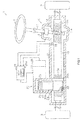
FIG. 1 is a sectional view showing a configuration of a steering system according to an embodiment of the invention; -
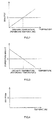
FIG. 2 is a graph showing a relation between a difference between a calculated steering angle and an actual steering angle of a steering wheel, and an ambient temperature in the embodiment; -
FIG. 3 is a map stored in a control portion in the embodiment, the map showing a relation between a coefficient (a steering angle change amount that changes depending on the ambient temperature) and a temperature; and -
FIG. 4 is a graph showing a relation between a deviation after the steering angle is corrected by the control portion, and the temperature in the embodiment. - Hereinafter, an embodiment of a rack assist type electric power steering system (EPS) will be described. As shown in
FIG. 1 , an EPS 1 includes asteering mechanism 10 that changes a steered angle ofwheels 3 depending on the rotation of asteering wheel 2, and anassist mechanism 20 that assists the steering of thesteering wheel 2. - The
steering mechanism 10 includes a steering shaft 11 that is connected to thesteering wheel 2, and a rack-and-pinion mechanism 12 to which the steering shaft 11 is connected. The rack-and-pinion mechanism 12 is accommodated in a housing 21 extending in the right-left direction of a vehicle body. The rack-and-pinion mechanism 12 includes apinion shaft 11a provided at an end portion of the steering shaft 11 on the side opposite to thesteering wheel 2, and a rack portion 13a provided at a portion of arack shaft 13 extending in the right-left direction of the vehicle body. Thewheels 3 are connected to respective ends of therack shaft 13. Accordingly, the rotation of thesteering wheel 2 is converted into an axial linear motion of therack shaft 13 by the rack-and-pinion mechanism 12. Thus, thewheels 3 are steered. In addition, the housing 21 is formed of aluminum, and therack shaft 13 is formed of steel. - The
assist mechanism 20 includes a brushless motor 22 (hereinafter referred to as a motor 22) that generates an assist force, and atransmission mechanism 24 that transmits the driving force of the motor 22 to therack shaft 13. - The motor 22 is fixed to the housing 21. An
output shaft 23 of the motor 22 is parallel to therack shaft 13. Thetransmission mechanism 24 includes abelt speed reducer 24a and aball screw 24b. Theball screw 24b includes aball screw portion 13b provided at a portion of therack shaft 13, and aball nut 26 screwed to theball screw portion 13b with a plurality of balls (not shown) interposed therebetween. Thebelt speed reducer 24a includes adriving pulley 25 connected to theoutput shaft 23, a drivenpulley 30 fixed to theball nut 26, and abelt 27 that transmits the rotation of thedriving pulley 25 to the drivenpulley 30. Accordingly, the rotation force of the motor 22 is transmitted to the drivenpulley 30 through thedriving pulley 25 and thebelt 27 and converted into the axial linear motion of therack shaft 13 through theball nut 26 that rotates together with the drivenpulley 30. - Next, the electrical configuration of the EPS 1 will be described. The EPS 1 includes a
torque sensor 14, atemperature sensor 15, a rotation angle sensor 28, and anECU 29. Thetorque sensor 14 is provided at the steering shaft 11. Thetorque sensor 14 detects steering torque that is applied to the steering shaft 11 in accordance with a driver's steering operation. Thetemperature sensor 15 is provided inside the housing 21 at a position in the vicinity of therack shaft 13. The rotation angle sensor 28 is provided in the motor 22, thereby detecting a rotation angle thereof. - The
ECU 29 calculates a steering angle of thesteering wheel 2 on the basis of a detection result from the rotation angle sensor 28 and an EPS gear ratio (a gear ratio between the rack portion 13a and thepinion shaft 11a and a speed reducing ratio of the transmission mechanism 24). - The coefficient of expansion of the
rack shaft 13 formed of steel is different from the coefficient of expansion of the housing 21 formed of aluminum. Therefore, when the temperature of therack shaft 13 has changed, the following problem occurs. A deviation occurs between a steering angle calculated on the basis of an output of the rotation angle sensor 28 for the motor 22 fixed to the housing 21 and the steering angle (the actual steering angle) of thesteering wheel 2 connected to therack shaft 13 supported in the housing 21 through the rack-and-pinion mechanism 12. - In order to cope with the caused deviation, the ECU 29 performs correction to cancel a deviation that is caused due to thermal displacement of the
rack shaft 13, when calculating the steering angle. A map M used for performing correction to cancel the amount of change in the steering angle due to a change in the temperature of therack shaft 13 is stored in advance in amemory 29a of theECU 29. - The
ECU 29 determines the amount of current (a current command value) that is supplied to the motor 22, on the basis of the corrected steering angle, a detection result obtained by thetorque sensor 14, and the like. An electric current in accordance with the current command value is supplied to the motor 22, whereby the motor 22 generates appropriate assist torque at each moment. - In addition, the
temperature sensor 15 corresponds to an estimate portion, and thememory 29a corresponds to a storage portion. Next, processing for correcting the steering angle performed by theECU 29 will be described. TheECU 29 calculates the steering angle of thesteering wheel 2 on the basis of the output of the rotation angle sensor 28 (a motor rotation angle) and the gear ratio of the rack portion 13a (the EPS gear ratio). Specifically, the steering angle is calculated by Equation 1 described below.
- There is the following correlation between the deviation that is a difference between the calculated steering angle and the actual steering angle, and the temperature of the
rack shaft 13. For example, as shown in the graph ofFIG. 2 , when the deviation at an ordinary temperature (reference temperature) is set to be 0, the deviation increases as the temperature of therack shaft 13 rises. The deviation similarly increases when the temperature decreases. - In order to eliminate the steering angle deviation due to the change in the temperature of the
rack shaft 13, theECU 29 corrects the calculated steering angle by using the map M so as to cancel the deviation. As shown inFIG. 3 , the map M shows a correlation between the temperature of therack shaft 13 and a correction amount. The correction amount is obtained by calculating, in advance, a steering angle that is required to eliminate the deviation that is caused depending on the temperature. Next, as shown byEquation 2, theECU 29 determines the correction amount corresponding to the detection result obtained by thetemperature sensor 15 with the use of the map M, and performs correction by adding the correction amount to the steering angle calculated according to Equation 1 described above.
- Thus, the
ECU 29 can determine the accurate steering angle by correcting the calculated steering angle by using the amount of change in the steering angle, which is caused depending on the temperature of the rack shaft 13 (i.e., by using the correction amount). That is, as shown inFIG. 4 , even if the temperature of therack shaft 13 changes, it is possible to ensure the sufficient accuracy of the calculated steering angle, by reducing the deviation, which is the amount of deviation of the steering angle, to 0. - The embodiment described above has the following advantageous effects. The
ECU 29 calculates the steering angle of thesteering wheel 2 based on the output of the rotation angle sensor 28 and the EPS gear ratio. Subsequently, theECU 29 corrects the calculated steering angle of thesteering wheel 2 on the basis of the temperature of the rack shaft 13 (precisely, the temperature around the rack shaft 13), which is detected by thetemperature sensor 15, and the map M stored in thememory 29a. Thus, it is possible to perform the correction to cancel the deviation between the steering angle of thesteering wheel 2, that is, the steering angle calculated by theECU 29 and the actual steering angle, the deviation being caused due to the change in the temperature of therack shaft 13. - The calculated steering angle itself of the
steering wheel 2 is corrected on the basis of the detection result obtained by thetemperature sensor 15. Therefore, as compared to the conventional electric power steering system in which the number of turns (the number of revolutions) of the steering shaft is corrected when the initial steering angle is calculated, it is possible to determine the steering angle more accurately. - The
ECU 29 corrects the calculated steering angle, every time the steering angle is calculated. Thus, even when a vehicle is in a state in which a temperature change is likely to occur, for example, when the vehicle is traveling at a low speed due to a traffic jam or the like, or when the vehicle that has been traveling stops and then immediately restarts traveling, it is possible to determine the accurate steering angle. - In addition, the embodiment described above can be implemented in the following forms in which the embodiment is appropriately changed. The
ECU 29 may correct the output of the rotation angle sensor 28, instead of the calculated steering angle. This case is different from the embodiment only in that the motor rotation angle is corrected, and a correction method and the like in this case are the same as those in the embodiment, the description thereof will be omitted. The same effects as those described above are obtained by correcting the output of the rotation angle sensor 28, which is used to calculate the steering angle. - For example, a temperature sensor provided in the rotation angle sensor 28, or a temperature sensor provided in a Hall IC that is used for the
torque sensor 14 may be used instead of thetemperature sensor 15 in this embodiment. Since a temperature sensor provided in an existing sensor is used, it is not necessary to provide a new temperature sensor. Therefore, it is possible to reduce the cost of the steering system and simplify the configuration of the steering system. - The temperature may be estimated from not only the temperature sensor, but also the resistance value of a coil of the motor 22, for example. In this case, the temperature is estimated by using a characteristic in which the resistance value of the coil increases in direct proportion to a change in the temperature. That is, the temperature of the
rack shaft 13 is estimated from the resistance value of the coil of the motor 22 that is present in the vicinity of therack shaft 13. Then, the same steering angle correction as that in this embodiment is performed on the basis of the estimated temperature of therack shaft 13. The resistance value of the coil corresponds to a characteristic value.
Claims (1)
- An electric power steering system (1) comprising:a housing (21);a rack shaft (13) that is accommodated in the housing (21), the rack shaft (13) reciprocating in an axial direction in accordance with rotation of a steering shaft (11), and the rack shaft (13) being formed of a material different from a material of which the housing (21) is formed;an electric motor (22) that is fixed to the housing (21) and applies an assist force to the rack shaft (13);one rotation angle sensor (28) that detects a rotation angle of the electric motor;a control portion (29) that controls driving of the electric motor; andan estimate portion (15) that estimates a temperature of the rack shaft (13) or a characteristic value that depends on the temperature,wherein the control portion (29) calculates a steering angle of a steering wheel (2) based on an output of the rotation angle sensor (28), determines a correction amount for canceling a deviation of the calculated steering angle or the output of the rotation angle sensor (28), based on an estimate result obtained by the estimate portion (15), and corrects the calculated steering angle or the output of the rotation angle sensor (28) by taking into account the correction amount, the deviation being caused due to a change in an ambient temperature around the rack shaft (13);the estimate portion (15) is a temperature sensor (15) disposed in a vicinity of the rack shaft (13),the control portion (29) includes a storage portion (29a) in which a map (M) is stored, the map (M) showing a correlation between the temperature of the rack shaft (13) and the correction amount;characterized in thatthe control portion (29) determines the correction amount corresponding to the temperature at each moment, based on the output of the temperature sensor (15) and the map (M) stored in the storage portion (29a), and corrects the calculated steering angle or the output of said only one rotation angle sensor (28) by adding the correction amount to the calculated steering angle or the output of said only one rotation angle sensor (28).
Applications Claiming Priority (1)
| Application Number | Priority Date | Filing Date | Title |
|---|---|---|---|
| JP2013043348A JP2014169061A (en) | 2013-03-05 | 2013-03-05 | Electric power steering device |
Publications (2)
| Publication Number | Publication Date |
|---|---|
| EP2774829A1 EP2774829A1 (en) | 2014-09-10 |
| EP2774829B1 true EP2774829B1 (en) | 2016-09-07 |
Family
ID=50238131
Family Applications (1)
| Application Number | Title | Priority Date | Filing Date |
|---|---|---|---|
| EP14156933.5A Not-in-force EP2774829B1 (en) | 2013-03-05 | 2014-02-27 | Electric power steering system |
Country Status (4)
| Country | Link |
|---|---|
| US (1) | US9174668B2 (en) |
| EP (1) | EP2774829B1 (en) |
| JP (1) | JP2014169061A (en) |
| CN (1) | CN104029716A (en) |
Families Citing this family (13)
| Publication number | Priority date | Publication date | Assignee | Title |
|---|---|---|---|---|
| JP2014169061A (en) * | 2013-03-05 | 2014-09-18 | Jtekt Corp | Electric power steering device |
| US20160075372A1 (en) * | 2014-09-12 | 2016-03-17 | GM Global Technology Operations LLC | Early fault detection for an eps system |
| DE112015004346T5 (en) * | 2014-09-24 | 2017-06-01 | Hitachi Automotive Systems, Ltd. | CONTROL DEVICE FOR VEHICLE-ASSEMBLED DEVICE AND POWER STEERING DEVICE |
| JP6394399B2 (en) * | 2015-01-09 | 2018-09-26 | 株式会社デンソー | Rotation angle detector |
| DE102015013965B4 (en) * | 2015-10-29 | 2022-02-03 | Thyssenkrupp Ag | Angle and torque measuring device |
| WO2018038108A1 (en) * | 2016-08-26 | 2018-03-01 | 日本精工株式会社 | Control device for electric power steering device |
| CN109863684B (en) | 2016-09-02 | 2023-06-06 | 康斯博格股份有限公司 | Technique for limiting current supplied to motor in electric power steering system |
| JP6744802B2 (en) * | 2016-10-28 | 2020-08-19 | 株式会社ジェイテクト | Steering control device |
| JP7131345B2 (en) * | 2017-12-14 | 2022-09-06 | トヨタ自動車株式会社 | steering system |
| JP6574830B2 (en) * | 2017-12-21 | 2019-09-11 | 本田技研工業株式会社 | Spoke angle deviation measuring device |
| US11383727B2 (en) * | 2018-03-19 | 2022-07-12 | Qualcomm Incorporated | Vehicle operation based on vehicular measurement data processing |
| US11254345B2 (en) | 2019-01-29 | 2022-02-22 | Steering Solutions Ip Holding Corporation | Securing steering wheel in steer-by-wire systems |
| US11192579B2 (en) * | 2019-01-31 | 2021-12-07 | Nsk Ltd. | Actuator control device used in steering of vehicle |
Family Cites Families (43)
| Publication number | Priority date | Publication date | Assignee | Title |
|---|---|---|---|---|
| JPS6035663A (en) * | 1983-08-08 | 1985-02-23 | Aisin Seiki Co Ltd | Motor power steering system |
| US4800974A (en) * | 1985-10-23 | 1989-01-31 | Trw Inc. | Electric steering gear |
| JPS62251273A (en) * | 1986-04-22 | 1987-11-02 | Honda Motor Co Ltd | Electrically driven power steering device |
| KR910000398B1 (en) * | 1986-06-12 | 1991-01-25 | 미쓰비시전기 주식회사 | Motor-driven power steering system for a vehicle |
| JPH0686221B2 (en) * | 1986-09-16 | 1994-11-02 | 本田技研工業株式会社 | Electric power steering device |
| JP3584832B2 (en) * | 2000-01-25 | 2004-11-04 | オムロン株式会社 | Electric power steering device |
| JP3687472B2 (en) * | 2000-03-13 | 2005-08-24 | 豊田工機株式会社 | Temperature detection device |
| JP3723748B2 (en) * | 2001-06-05 | 2005-12-07 | 三菱電機株式会社 | Electric power steering control system |
| US6900607B2 (en) * | 2001-08-17 | 2005-05-31 | Delphi Technologies, Inc. | Combined feedforward and feedback parameter estimation for electric machines |
| US7071649B2 (en) * | 2001-08-17 | 2006-07-04 | Delphi Technologies, Inc. | Active temperature estimation for electric machines |
| US7199549B2 (en) * | 2001-08-17 | 2007-04-03 | Delphi Technologies, Inc | Feedback parameter estimation for electric machines |
| JP4019873B2 (en) * | 2001-10-12 | 2007-12-12 | 日産自動車株式会社 | Rudder angle ratio control device |
| JP3938902B2 (en) * | 2002-11-27 | 2007-06-27 | 株式会社ジェイテクト | Angle detection device and torque sensor including the same |
| JP4131393B2 (en) * | 2003-02-17 | 2008-08-13 | 株式会社デンソー | Control device for electric power steering |
| JP3891288B2 (en) * | 2003-03-28 | 2007-03-14 | 株式会社ジェイテクト | Electric power steering device |
| JP4046005B2 (en) * | 2003-05-12 | 2008-02-13 | 株式会社デンソー | Electric motor drive device and electric power steering device |
| FR2869862B1 (en) * | 2004-05-06 | 2008-12-26 | Favess Co Ltd | DEVICE FORMING POWER ASSISTED STEERING |
| JP3931181B2 (en) * | 2004-06-02 | 2007-06-13 | 三菱電機株式会社 | Electric power steering device |
| JP4600653B2 (en) * | 2004-10-28 | 2010-12-15 | 株式会社ジェイテクト | Steering control device |
| US7163080B2 (en) * | 2005-03-11 | 2007-01-16 | Trw Automotive U.S. Llc | Method and apparatus for detecting a failed temperature sensor in an electric assist steering system |
| DE102006010357A1 (en) * | 2006-03-07 | 2007-09-13 | Zf Lenksysteme Gmbh | Electromechanical steering device for a motor vehicle has an electric motor and power-output electronics for triggering the electric motor |
| JP4296186B2 (en) * | 2006-04-19 | 2009-07-15 | 三菱電機株式会社 | Electric power steering device |
| CA2593889C (en) * | 2006-07-26 | 2011-09-27 | Sumitaka Ogawa | Motor protection system |
| JP2008049968A (en) * | 2006-08-28 | 2008-03-06 | Hitachi Ltd | Power steering device |
| JP4297144B2 (en) | 2006-09-15 | 2009-07-15 | トヨタ自動車株式会社 | Vehicle steering control device |
| JP4907283B2 (en) * | 2006-09-27 | 2012-03-28 | 株式会社ショーワ | Electric power steering device |
| US8251172B2 (en) * | 2008-02-07 | 2012-08-28 | Jtekt Corporation | Electric power steering device |
| JP5369527B2 (en) | 2008-07-29 | 2013-12-18 | 株式会社ジェイテクト | Rudder angle detector |
| KR101285423B1 (en) * | 2009-09-15 | 2013-07-12 | 주식회사 만도 | Electric power steering apparatus and control method for current thereof |
| JP5269748B2 (en) * | 2009-11-05 | 2013-08-21 | 本田技研工業株式会社 | Overheat protection device |
| JP5062245B2 (en) * | 2009-12-25 | 2012-10-31 | トヨタ自動車株式会社 | Load driving device and vehicle equipped with the same |
| KR101286823B1 (en) * | 2009-12-31 | 2013-07-17 | 현대모비스 주식회사 | Protecting method of motor driven steering system from overheat |
| KR20110085376A (en) * | 2010-01-20 | 2011-07-27 | 현대모비스 주식회사 | Protecting method of motor driven steering system from overheat |
| JP5355530B2 (en) * | 2010-10-26 | 2013-11-27 | 三菱電機株式会社 | Electric power steering device |
| JP5817418B2 (en) * | 2011-02-14 | 2015-11-18 | 株式会社ジェイテクト | Electric power steering device |
| WO2012144047A1 (en) * | 2011-04-21 | 2012-10-26 | 三菱電機株式会社 | Electric power steering control device |
| JP5318179B2 (en) * | 2011-05-30 | 2013-10-16 | 三菱電機株式会社 | Control device for internal combustion engine |
| JP5327277B2 (en) * | 2011-06-08 | 2013-10-30 | 日本精工株式会社 | Control device for electric power steering device |
| JP5397785B2 (en) * | 2011-08-01 | 2014-01-22 | 株式会社デンソー | Control device for three-phase rotating machine |
| DE102011121272A1 (en) * | 2011-12-15 | 2013-06-20 | Audi Ag | Method and device for temperature-dependent control of an electric motor |
| EP2813414B1 (en) * | 2012-02-06 | 2018-04-04 | NSK Ltd. | Electric power steering device |
| DE102013201468A1 (en) * | 2013-01-30 | 2014-07-31 | Zf Lenksysteme Gmbh | METHOD FOR OPERATING AN ELECTRIC MOTOR |
| JP2014169061A (en) * | 2013-03-05 | 2014-09-18 | Jtekt Corp | Electric power steering device |
-
2013
- 2013-03-05 JP JP2013043348A patent/JP2014169061A/en active Pending
-
2014
- 2014-02-26 US US14/190,772 patent/US9174668B2/en not_active Expired - Fee Related
- 2014-02-27 EP EP14156933.5A patent/EP2774829B1/en not_active Not-in-force
- 2014-02-28 CN CN201410072595.1A patent/CN104029716A/en active Pending
Also Published As
| Publication number | Publication date |
|---|---|
| JP2014169061A (en) | 2014-09-18 |
| CN104029716A (en) | 2014-09-10 |
| EP2774829A1 (en) | 2014-09-10 |
| US9174668B2 (en) | 2015-11-03 |
| US20140257642A1 (en) | 2014-09-11 |
Similar Documents
| Publication | Publication Date | Title |
|---|---|---|
| EP2774829B1 (en) | Electric power steering system | |
| EP2078661B1 (en) | Steering System for vehicle | |
| US9002579B2 (en) | Steering assist device | |
| EP2792574B1 (en) | Electric power steering system | |
| KR101285423B1 (en) | Electric power steering apparatus and control method for current thereof | |
| EP2527229B1 (en) | Electric power steering system | |
| CN107215385B (en) | Steering torque compensation apparatus and method for electric power steering system | |
| US9701334B2 (en) | Vehicle steering device | |
| US20170334480A1 (en) | Electric power steering device | |
| EP3056410B1 (en) | Drive assist control apparatus | |
| EP3756977A1 (en) | Steering device | |
| EP2426031A2 (en) | Electric power steering system | |
| US20120330511A1 (en) | Steering control system | |
| JP4627012B2 (en) | Electric power steering device | |
| JP4545054B2 (en) | Electric power steering device | |
| JP4545055B2 (en) | Electric power steering device | |
| EP3505423B1 (en) | Steering control device | |
| JP5867287B2 (en) | Steering angle detection device for vehicle and electric power steering device | |
| JP4928581B2 (en) | Sensor midpoint correction method | |
| JP2009143427A (en) | Steering device | |
| EP2555414B1 (en) | Motor control unit and electric power steering system | |
| JP6486605B2 (en) | Steering control device | |
| JP2014189115A (en) | Steering angle detection device | |
| EP3967574B1 (en) | Steering system | |
| KR20180053789A (en) | Method for compensating offset of current sensor |
Legal Events
| Date | Code | Title | Description |
|---|---|---|---|
| PUAI | Public reference made under article 153(3) epc to a published international application that has entered the european phase |
Free format text: ORIGINAL CODE: 0009012 |
|
| 17P | Request for examination filed |
Effective date: 20140227 |
|
| AK | Designated contracting states |
Kind code of ref document: A1 Designated state(s): AL AT BE BG CH CY CZ DE DK EE ES FI FR GB GR HR HU IE IS IT LI LT LU LV MC MK MT NL NO PL PT RO RS SE SI SK SM TR |
|
| AX | Request for extension of the european patent |
Extension state: BA ME |
|
| R17P | Request for examination filed (corrected) |
Effective date: 20150309 |
|
| RBV | Designated contracting states (corrected) |
Designated state(s): AL AT BE BG CH CY CZ DE DK EE ES FI FR GB GR HR HU IE IS IT LI LT LU LV MC MK MT NL NO PL PT RO RS SE SI SK SM TR |
|
| 17Q | First examination report despatched |
Effective date: 20150805 |
|
| GRAP | Despatch of communication of intention to grant a patent |
Free format text: ORIGINAL CODE: EPIDOSNIGR1 |
|
| RIC1 | Information provided on ipc code assigned before grant |
Ipc: B62D 6/00 20060101ALN20160215BHEP Ipc: B62D 3/12 20060101ALN20160215BHEP Ipc: B62D 5/04 20060101ALN20160215BHEP Ipc: B62D 15/02 20060101AFI20160215BHEP |
|
| INTG | Intention to grant announced |
Effective date: 20160304 |
|
| GRAS | Grant fee paid |
Free format text: ORIGINAL CODE: EPIDOSNIGR3 |
|
| GRAA | (expected) grant |
Free format text: ORIGINAL CODE: 0009210 |
|
| RIN1 | Information on inventor provided before grant (corrected) |
Inventor name: KICHISE, HIROSHI |
|
| AK | Designated contracting states |
Kind code of ref document: B1 Designated state(s): AL AT BE BG CH CY CZ DE DK EE ES FI FR GB GR HR HU IE IS IT LI LT LU LV MC MK MT NL NO PL PT RO RS SE SI SK SM TR |
|
| REG | Reference to a national code |
Ref country code: GB Ref legal event code: FG4D |
|
| REG | Reference to a national code |
Ref country code: CH Ref legal event code: EP |
|
| REG | Reference to a national code |
Ref country code: IE Ref legal event code: FG4D |
|
| REG | Reference to a national code |
Ref country code: AT Ref legal event code: REF Ref document number: 826550 Country of ref document: AT Kind code of ref document: T Effective date: 20161015 |
|
| REG | Reference to a national code |
Ref country code: DE Ref legal event code: R096 Ref document number: 602014003445 Country of ref document: DE |
|
| REG | Reference to a national code |
Ref country code: LT Ref legal event code: MG4D |
|
| REG | Reference to a national code |
Ref country code: NL Ref legal event code: MP Effective date: 20160907 |
|
| REG | Reference to a national code |
Ref country code: FR Ref legal event code: PLFP Year of fee payment: 4 |
|
| PG25 | Lapsed in a contracting state [announced via postgrant information from national office to epo] |
Ref country code: HR Free format text: LAPSE BECAUSE OF FAILURE TO SUBMIT A TRANSLATION OF THE DESCRIPTION OR TO PAY THE FEE WITHIN THE PRESCRIBED TIME-LIMIT Effective date: 20160907 Ref country code: RS Free format text: LAPSE BECAUSE OF FAILURE TO SUBMIT A TRANSLATION OF THE DESCRIPTION OR TO PAY THE FEE WITHIN THE PRESCRIBED TIME-LIMIT Effective date: 20160907 Ref country code: NO Free format text: LAPSE BECAUSE OF FAILURE TO SUBMIT A TRANSLATION OF THE DESCRIPTION OR TO PAY THE FEE WITHIN THE PRESCRIBED TIME-LIMIT Effective date: 20161207 Ref country code: FI Free format text: LAPSE BECAUSE OF FAILURE TO SUBMIT A TRANSLATION OF THE DESCRIPTION OR TO PAY THE FEE WITHIN THE PRESCRIBED TIME-LIMIT Effective date: 20160907 Ref country code: LT Free format text: LAPSE BECAUSE OF FAILURE TO SUBMIT A TRANSLATION OF THE DESCRIPTION OR TO PAY THE FEE WITHIN THE PRESCRIBED TIME-LIMIT Effective date: 20160907 |
|
| REG | Reference to a national code |
Ref country code: AT Ref legal event code: MK05 Ref document number: 826550 Country of ref document: AT Kind code of ref document: T Effective date: 20160907 |
|
| PG25 | Lapsed in a contracting state [announced via postgrant information from national office to epo] |
Ref country code: GR Free format text: LAPSE BECAUSE OF FAILURE TO SUBMIT A TRANSLATION OF THE DESCRIPTION OR TO PAY THE FEE WITHIN THE PRESCRIBED TIME-LIMIT Effective date: 20161208 Ref country code: LV Free format text: LAPSE BECAUSE OF FAILURE TO SUBMIT A TRANSLATION OF THE DESCRIPTION OR TO PAY THE FEE WITHIN THE PRESCRIBED TIME-LIMIT Effective date: 20160907 Ref country code: ES Free format text: LAPSE BECAUSE OF FAILURE TO SUBMIT A TRANSLATION OF THE DESCRIPTION OR TO PAY THE FEE WITHIN THE PRESCRIBED TIME-LIMIT Effective date: 20160907 Ref country code: NL Free format text: LAPSE BECAUSE OF FAILURE TO SUBMIT A TRANSLATION OF THE DESCRIPTION OR TO PAY THE FEE WITHIN THE PRESCRIBED TIME-LIMIT Effective date: 20160907 Ref country code: SE Free format text: LAPSE BECAUSE OF FAILURE TO SUBMIT A TRANSLATION OF THE DESCRIPTION OR TO PAY THE FEE WITHIN THE PRESCRIBED TIME-LIMIT Effective date: 20160907 |
|
| PG25 | Lapsed in a contracting state [announced via postgrant information from national office to epo] |
Ref country code: EE Free format text: LAPSE BECAUSE OF FAILURE TO SUBMIT A TRANSLATION OF THE DESCRIPTION OR TO PAY THE FEE WITHIN THE PRESCRIBED TIME-LIMIT Effective date: 20160907 Ref country code: RO Free format text: LAPSE BECAUSE OF FAILURE TO SUBMIT A TRANSLATION OF THE DESCRIPTION OR TO PAY THE FEE WITHIN THE PRESCRIBED TIME-LIMIT Effective date: 20160907 |
|
| PGFP | Annual fee paid to national office [announced via postgrant information from national office to epo] |
Ref country code: DE Payment date: 20170221 Year of fee payment: 4 Ref country code: FR Payment date: 20170112 Year of fee payment: 4 |
|
| PG25 | Lapsed in a contracting state [announced via postgrant information from national office to epo] |
Ref country code: AT Free format text: LAPSE BECAUSE OF FAILURE TO SUBMIT A TRANSLATION OF THE DESCRIPTION OR TO PAY THE FEE WITHIN THE PRESCRIBED TIME-LIMIT Effective date: 20160907 Ref country code: PT Free format text: LAPSE BECAUSE OF FAILURE TO SUBMIT A TRANSLATION OF THE DESCRIPTION OR TO PAY THE FEE WITHIN THE PRESCRIBED TIME-LIMIT Effective date: 20170109 Ref country code: CZ Free format text: LAPSE BECAUSE OF FAILURE TO SUBMIT A TRANSLATION OF THE DESCRIPTION OR TO PAY THE FEE WITHIN THE PRESCRIBED TIME-LIMIT Effective date: 20160907 Ref country code: IS Free format text: LAPSE BECAUSE OF FAILURE TO SUBMIT A TRANSLATION OF THE DESCRIPTION OR TO PAY THE FEE WITHIN THE PRESCRIBED TIME-LIMIT Effective date: 20170107 Ref country code: BG Free format text: LAPSE BECAUSE OF FAILURE TO SUBMIT A TRANSLATION OF THE DESCRIPTION OR TO PAY THE FEE WITHIN THE PRESCRIBED TIME-LIMIT Effective date: 20161207 Ref country code: SK Free format text: LAPSE BECAUSE OF FAILURE TO SUBMIT A TRANSLATION OF THE DESCRIPTION OR TO PAY THE FEE WITHIN THE PRESCRIBED TIME-LIMIT Effective date: 20160907 Ref country code: PL Free format text: LAPSE BECAUSE OF FAILURE TO SUBMIT A TRANSLATION OF THE DESCRIPTION OR TO PAY THE FEE WITHIN THE PRESCRIBED TIME-LIMIT Effective date: 20160907 Ref country code: BE Free format text: LAPSE BECAUSE OF FAILURE TO SUBMIT A TRANSLATION OF THE DESCRIPTION OR TO PAY THE FEE WITHIN THE PRESCRIBED TIME-LIMIT Effective date: 20160907 Ref country code: SM Free format text: LAPSE BECAUSE OF FAILURE TO SUBMIT A TRANSLATION OF THE DESCRIPTION OR TO PAY THE FEE WITHIN THE PRESCRIBED TIME-LIMIT Effective date: 20160907 |
|
| REG | Reference to a national code |
Ref country code: DE Ref legal event code: R097 Ref document number: 602014003445 Country of ref document: DE |
|
| PG25 | Lapsed in a contracting state [announced via postgrant information from national office to epo] |
Ref country code: IT Free format text: LAPSE BECAUSE OF FAILURE TO SUBMIT A TRANSLATION OF THE DESCRIPTION OR TO PAY THE FEE WITHIN THE PRESCRIBED TIME-LIMIT Effective date: 20160907 |
|
| PLBE | No opposition filed within time limit |
Free format text: ORIGINAL CODE: 0009261 |
|
| STAA | Information on the status of an ep patent application or granted ep patent |
Free format text: STATUS: NO OPPOSITION FILED WITHIN TIME LIMIT |
|
| PG25 | Lapsed in a contracting state [announced via postgrant information from national office to epo] |
Ref country code: DK Free format text: LAPSE BECAUSE OF FAILURE TO SUBMIT A TRANSLATION OF THE DESCRIPTION OR TO PAY THE FEE WITHIN THE PRESCRIBED TIME-LIMIT Effective date: 20160907 |
|
| 26N | No opposition filed |
Effective date: 20170608 |
|
| PG25 | Lapsed in a contracting state [announced via postgrant information from national office to epo] |
Ref country code: SI Free format text: LAPSE BECAUSE OF FAILURE TO SUBMIT A TRANSLATION OF THE DESCRIPTION OR TO PAY THE FEE WITHIN THE PRESCRIBED TIME-LIMIT Effective date: 20160907 |
|
| PG25 | Lapsed in a contracting state [announced via postgrant information from national office to epo] |
Ref country code: MC Free format text: LAPSE BECAUSE OF FAILURE TO SUBMIT A TRANSLATION OF THE DESCRIPTION OR TO PAY THE FEE WITHIN THE PRESCRIBED TIME-LIMIT Effective date: 20160907 |
|
| REG | Reference to a national code |
Ref country code: CH Ref legal event code: PL |
|
| PG25 | Lapsed in a contracting state [announced via postgrant information from national office to epo] |
Ref country code: CH Free format text: LAPSE BECAUSE OF NON-PAYMENT OF DUE FEES Effective date: 20170228 Ref country code: LI Free format text: LAPSE BECAUSE OF NON-PAYMENT OF DUE FEES Effective date: 20170228 |
|
| REG | Reference to a national code |
Ref country code: IE Ref legal event code: MM4A |
|
| PG25 | Lapsed in a contracting state [announced via postgrant information from national office to epo] |
Ref country code: LU Free format text: LAPSE BECAUSE OF NON-PAYMENT OF DUE FEES Effective date: 20170227 |
|
| PG25 | Lapsed in a contracting state [announced via postgrant information from national office to epo] |
Ref country code: IE Free format text: LAPSE BECAUSE OF NON-PAYMENT OF DUE FEES Effective date: 20170227 |
|
| REG | Reference to a national code |
Ref country code: DE Ref legal event code: R119 Ref document number: 602014003445 Country of ref document: DE |
|
| PG25 | Lapsed in a contracting state [announced via postgrant information from national office to epo] |
Ref country code: MT Free format text: LAPSE BECAUSE OF NON-PAYMENT OF DUE FEES Effective date: 20170227 |
|
| GBPC | Gb: european patent ceased through non-payment of renewal fee |
Effective date: 20180227 |
|
| PG25 | Lapsed in a contracting state [announced via postgrant information from national office to epo] |
Ref country code: AL Free format text: LAPSE BECAUSE OF FAILURE TO SUBMIT A TRANSLATION OF THE DESCRIPTION OR TO PAY THE FEE WITHIN THE PRESCRIBED TIME-LIMIT Effective date: 20160907 |
|
| REG | Reference to a national code |
Ref country code: FR Ref legal event code: ST Effective date: 20181031 |
|
| PG25 | Lapsed in a contracting state [announced via postgrant information from national office to epo] |
Ref country code: DE Free format text: LAPSE BECAUSE OF NON-PAYMENT OF DUE FEES Effective date: 20180901 |
|
| PG25 | Lapsed in a contracting state [announced via postgrant information from national office to epo] |
Ref country code: GB Free format text: LAPSE BECAUSE OF NON-PAYMENT OF DUE FEES Effective date: 20180227 Ref country code: FR Free format text: LAPSE BECAUSE OF NON-PAYMENT OF DUE FEES Effective date: 20180228 |
|
| PG25 | Lapsed in a contracting state [announced via postgrant information from national office to epo] |
Ref country code: HU Free format text: LAPSE BECAUSE OF FAILURE TO SUBMIT A TRANSLATION OF THE DESCRIPTION OR TO PAY THE FEE WITHIN THE PRESCRIBED TIME-LIMIT; INVALID AB INITIO Effective date: 20140227 |
|
| PG25 | Lapsed in a contracting state [announced via postgrant information from national office to epo] |
Ref country code: CY Free format text: LAPSE BECAUSE OF NON-PAYMENT OF DUE FEES Effective date: 20160907 |
|
| PG25 | Lapsed in a contracting state [announced via postgrant information from national office to epo] |
Ref country code: MK Free format text: LAPSE BECAUSE OF FAILURE TO SUBMIT A TRANSLATION OF THE DESCRIPTION OR TO PAY THE FEE WITHIN THE PRESCRIBED TIME-LIMIT Effective date: 20160907 |
|
| PG25 | Lapsed in a contracting state [announced via postgrant information from national office to epo] |
Ref country code: TR Free format text: LAPSE BECAUSE OF FAILURE TO SUBMIT A TRANSLATION OF THE DESCRIPTION OR TO PAY THE FEE WITHIN THE PRESCRIBED TIME-LIMIT Effective date: 20160907 |