EP2774797A1 - Power source system and vehicle provided therewith, and method of controlling power source system - Google Patents
Power source system and vehicle provided therewith, and method of controlling power source system Download PDFInfo
- Publication number
- EP2774797A1 EP2774797A1 EP11875036.3A EP11875036A EP2774797A1 EP 2774797 A1 EP2774797 A1 EP 2774797A1 EP 11875036 A EP11875036 A EP 11875036A EP 2774797 A1 EP2774797 A1 EP 2774797A1
- Authority
- EP
- European Patent Office
- Prior art keywords
- power
- charging
- power storage
- storage device
- vehicle
- Prior art date
- Legal status (The legal status is an assumption and is not a legal conclusion. Google has not performed a legal analysis and makes no representation as to the accuracy of the status listed.)
- Granted
Links
Images




Classifications
-
- B—PERFORMING OPERATIONS; TRANSPORTING
- B60—VEHICLES IN GENERAL
- B60L—PROPULSION OF ELECTRICALLY-PROPELLED VEHICLES; SUPPLYING ELECTRIC POWER FOR AUXILIARY EQUIPMENT OF ELECTRICALLY-PROPELLED VEHICLES; ELECTRODYNAMIC BRAKE SYSTEMS FOR VEHICLES IN GENERAL; MAGNETIC SUSPENSION OR LEVITATION FOR VEHICLES; MONITORING OPERATING VARIABLES OF ELECTRICALLY-PROPELLED VEHICLES; ELECTRIC SAFETY DEVICES FOR ELECTRICALLY-PROPELLED VEHICLES
- B60L1/00—Supplying electric power to auxiliary equipment of vehicles
- B60L1/003—Supplying electric power to auxiliary equipment of vehicles to auxiliary motors, e.g. for pumps, compressors
-
- B—PERFORMING OPERATIONS; TRANSPORTING
- B60—VEHICLES IN GENERAL
- B60L—PROPULSION OF ELECTRICALLY-PROPELLED VEHICLES; SUPPLYING ELECTRIC POWER FOR AUXILIARY EQUIPMENT OF ELECTRICALLY-PROPELLED VEHICLES; ELECTRODYNAMIC BRAKE SYSTEMS FOR VEHICLES IN GENERAL; MAGNETIC SUSPENSION OR LEVITATION FOR VEHICLES; MONITORING OPERATING VARIABLES OF ELECTRICALLY-PROPELLED VEHICLES; ELECTRIC SAFETY DEVICES FOR ELECTRICALLY-PROPELLED VEHICLES
- B60L15/00—Methods, circuits, or devices for controlling the traction-motor speed of electrically-propelled vehicles
- B60L15/007—Physical arrangements or structures of drive train converters specially adapted for the propulsion motors of electric vehicles
-
- B—PERFORMING OPERATIONS; TRANSPORTING
- B60—VEHICLES IN GENERAL
- B60L—PROPULSION OF ELECTRICALLY-PROPELLED VEHICLES; SUPPLYING ELECTRIC POWER FOR AUXILIARY EQUIPMENT OF ELECTRICALLY-PROPELLED VEHICLES; ELECTRODYNAMIC BRAKE SYSTEMS FOR VEHICLES IN GENERAL; MAGNETIC SUSPENSION OR LEVITATION FOR VEHICLES; MONITORING OPERATING VARIABLES OF ELECTRICALLY-PROPELLED VEHICLES; ELECTRIC SAFETY DEVICES FOR ELECTRICALLY-PROPELLED VEHICLES
- B60L50/00—Electric propulsion with power supplied within the vehicle
- B60L50/10—Electric propulsion with power supplied within the vehicle using propulsion power supplied by engine-driven generators, e.g. generators driven by combustion engines
- B60L50/16—Electric propulsion with power supplied within the vehicle using propulsion power supplied by engine-driven generators, e.g. generators driven by combustion engines with provision for separate direct mechanical propulsion
-
- B—PERFORMING OPERATIONS; TRANSPORTING
- B60—VEHICLES IN GENERAL
- B60L—PROPULSION OF ELECTRICALLY-PROPELLED VEHICLES; SUPPLYING ELECTRIC POWER FOR AUXILIARY EQUIPMENT OF ELECTRICALLY-PROPELLED VEHICLES; ELECTRODYNAMIC BRAKE SYSTEMS FOR VEHICLES IN GENERAL; MAGNETIC SUSPENSION OR LEVITATION FOR VEHICLES; MONITORING OPERATING VARIABLES OF ELECTRICALLY-PROPELLED VEHICLES; ELECTRIC SAFETY DEVICES FOR ELECTRICALLY-PROPELLED VEHICLES
- B60L50/00—Electric propulsion with power supplied within the vehicle
- B60L50/40—Electric propulsion with power supplied within the vehicle using propulsion power supplied by capacitors
-
- B—PERFORMING OPERATIONS; TRANSPORTING
- B60—VEHICLES IN GENERAL
- B60L—PROPULSION OF ELECTRICALLY-PROPELLED VEHICLES; SUPPLYING ELECTRIC POWER FOR AUXILIARY EQUIPMENT OF ELECTRICALLY-PROPELLED VEHICLES; ELECTRODYNAMIC BRAKE SYSTEMS FOR VEHICLES IN GENERAL; MAGNETIC SUSPENSION OR LEVITATION FOR VEHICLES; MONITORING OPERATING VARIABLES OF ELECTRICALLY-PROPELLED VEHICLES; ELECTRIC SAFETY DEVICES FOR ELECTRICALLY-PROPELLED VEHICLES
- B60L50/00—Electric propulsion with power supplied within the vehicle
- B60L50/50—Electric propulsion with power supplied within the vehicle using propulsion power supplied by batteries or fuel cells
- B60L50/60—Electric propulsion with power supplied within the vehicle using propulsion power supplied by batteries or fuel cells using power supplied by batteries
- B60L50/61—Electric propulsion with power supplied within the vehicle using propulsion power supplied by batteries or fuel cells using power supplied by batteries by batteries charged by engine-driven generators, e.g. series hybrid electric vehicles
-
- B—PERFORMING OPERATIONS; TRANSPORTING
- B60—VEHICLES IN GENERAL
- B60L—PROPULSION OF ELECTRICALLY-PROPELLED VEHICLES; SUPPLYING ELECTRIC POWER FOR AUXILIARY EQUIPMENT OF ELECTRICALLY-PROPELLED VEHICLES; ELECTRODYNAMIC BRAKE SYSTEMS FOR VEHICLES IN GENERAL; MAGNETIC SUSPENSION OR LEVITATION FOR VEHICLES; MONITORING OPERATING VARIABLES OF ELECTRICALLY-PROPELLED VEHICLES; ELECTRIC SAFETY DEVICES FOR ELECTRICALLY-PROPELLED VEHICLES
- B60L53/00—Methods of charging batteries, specially adapted for electric vehicles; Charging stations or on-board charging equipment therefor; Exchange of energy storage elements in electric vehicles
- B60L53/20—Methods of charging batteries, specially adapted for electric vehicles; Charging stations or on-board charging equipment therefor; Exchange of energy storage elements in electric vehicles characterised by converters located in the vehicle
-
- B—PERFORMING OPERATIONS; TRANSPORTING
- B60—VEHICLES IN GENERAL
- B60L—PROPULSION OF ELECTRICALLY-PROPELLED VEHICLES; SUPPLYING ELECTRIC POWER FOR AUXILIARY EQUIPMENT OF ELECTRICALLY-PROPELLED VEHICLES; ELECTRODYNAMIC BRAKE SYSTEMS FOR VEHICLES IN GENERAL; MAGNETIC SUSPENSION OR LEVITATION FOR VEHICLES; MONITORING OPERATING VARIABLES OF ELECTRICALLY-PROPELLED VEHICLES; ELECTRIC SAFETY DEVICES FOR ELECTRICALLY-PROPELLED VEHICLES
- B60L53/00—Methods of charging batteries, specially adapted for electric vehicles; Charging stations or on-board charging equipment therefor; Exchange of energy storage elements in electric vehicles
- B60L53/60—Monitoring or controlling charging stations
- B60L53/63—Monitoring or controlling charging stations in response to network capacity
-
- B—PERFORMING OPERATIONS; TRANSPORTING
- B60—VEHICLES IN GENERAL
- B60L—PROPULSION OF ELECTRICALLY-PROPELLED VEHICLES; SUPPLYING ELECTRIC POWER FOR AUXILIARY EQUIPMENT OF ELECTRICALLY-PROPELLED VEHICLES; ELECTRODYNAMIC BRAKE SYSTEMS FOR VEHICLES IN GENERAL; MAGNETIC SUSPENSION OR LEVITATION FOR VEHICLES; MONITORING OPERATING VARIABLES OF ELECTRICALLY-PROPELLED VEHICLES; ELECTRIC SAFETY DEVICES FOR ELECTRICALLY-PROPELLED VEHICLES
- B60L53/00—Methods of charging batteries, specially adapted for electric vehicles; Charging stations or on-board charging equipment therefor; Exchange of energy storage elements in electric vehicles
- B60L53/60—Monitoring or controlling charging stations
- B60L53/65—Monitoring or controlling charging stations involving identification of vehicles or their battery types
-
- B—PERFORMING OPERATIONS; TRANSPORTING
- B60—VEHICLES IN GENERAL
- B60L—PROPULSION OF ELECTRICALLY-PROPELLED VEHICLES; SUPPLYING ELECTRIC POWER FOR AUXILIARY EQUIPMENT OF ELECTRICALLY-PROPELLED VEHICLES; ELECTRODYNAMIC BRAKE SYSTEMS FOR VEHICLES IN GENERAL; MAGNETIC SUSPENSION OR LEVITATION FOR VEHICLES; MONITORING OPERATING VARIABLES OF ELECTRICALLY-PROPELLED VEHICLES; ELECTRIC SAFETY DEVICES FOR ELECTRICALLY-PROPELLED VEHICLES
- B60L55/00—Arrangements for supplying energy stored within a vehicle to a power network, i.e. vehicle-to-grid [V2G] arrangements
-
- B—PERFORMING OPERATIONS; TRANSPORTING
- B60—VEHICLES IN GENERAL
- B60L—PROPULSION OF ELECTRICALLY-PROPELLED VEHICLES; SUPPLYING ELECTRIC POWER FOR AUXILIARY EQUIPMENT OF ELECTRICALLY-PROPELLED VEHICLES; ELECTRODYNAMIC BRAKE SYSTEMS FOR VEHICLES IN GENERAL; MAGNETIC SUSPENSION OR LEVITATION FOR VEHICLES; MONITORING OPERATING VARIABLES OF ELECTRICALLY-PROPELLED VEHICLES; ELECTRIC SAFETY DEVICES FOR ELECTRICALLY-PROPELLED VEHICLES
- B60L58/00—Methods or circuit arrangements for monitoring or controlling batteries or fuel cells, specially adapted for electric vehicles
- B60L58/10—Methods or circuit arrangements for monitoring or controlling batteries or fuel cells, specially adapted for electric vehicles for monitoring or controlling batteries
- B60L58/18—Methods or circuit arrangements for monitoring or controlling batteries or fuel cells, specially adapted for electric vehicles for monitoring or controlling batteries of two or more battery modules
- B60L58/20—Methods or circuit arrangements for monitoring or controlling batteries or fuel cells, specially adapted for electric vehicles for monitoring or controlling batteries of two or more battery modules having different nominal voltages
-
- B—PERFORMING OPERATIONS; TRANSPORTING
- B60—VEHICLES IN GENERAL
- B60L—PROPULSION OF ELECTRICALLY-PROPELLED VEHICLES; SUPPLYING ELECTRIC POWER FOR AUXILIARY EQUIPMENT OF ELECTRICALLY-PROPELLED VEHICLES; ELECTRODYNAMIC BRAKE SYSTEMS FOR VEHICLES IN GENERAL; MAGNETIC SUSPENSION OR LEVITATION FOR VEHICLES; MONITORING OPERATING VARIABLES OF ELECTRICALLY-PROPELLED VEHICLES; ELECTRIC SAFETY DEVICES FOR ELECTRICALLY-PROPELLED VEHICLES
- B60L2210/00—Converter types
- B60L2210/10—DC to DC converters
- B60L2210/12—Buck converters
-
- B—PERFORMING OPERATIONS; TRANSPORTING
- B60—VEHICLES IN GENERAL
- B60L—PROPULSION OF ELECTRICALLY-PROPELLED VEHICLES; SUPPLYING ELECTRIC POWER FOR AUXILIARY EQUIPMENT OF ELECTRICALLY-PROPELLED VEHICLES; ELECTRODYNAMIC BRAKE SYSTEMS FOR VEHICLES IN GENERAL; MAGNETIC SUSPENSION OR LEVITATION FOR VEHICLES; MONITORING OPERATING VARIABLES OF ELECTRICALLY-PROPELLED VEHICLES; ELECTRIC SAFETY DEVICES FOR ELECTRICALLY-PROPELLED VEHICLES
- B60L2210/00—Converter types
- B60L2210/10—DC to DC converters
- B60L2210/14—Boost converters
-
- B—PERFORMING OPERATIONS; TRANSPORTING
- B60—VEHICLES IN GENERAL
- B60L—PROPULSION OF ELECTRICALLY-PROPELLED VEHICLES; SUPPLYING ELECTRIC POWER FOR AUXILIARY EQUIPMENT OF ELECTRICALLY-PROPELLED VEHICLES; ELECTRODYNAMIC BRAKE SYSTEMS FOR VEHICLES IN GENERAL; MAGNETIC SUSPENSION OR LEVITATION FOR VEHICLES; MONITORING OPERATING VARIABLES OF ELECTRICALLY-PROPELLED VEHICLES; ELECTRIC SAFETY DEVICES FOR ELECTRICALLY-PROPELLED VEHICLES
- B60L2210/00—Converter types
- B60L2210/40—DC to AC converters
-
- B—PERFORMING OPERATIONS; TRANSPORTING
- B60—VEHICLES IN GENERAL
- B60L—PROPULSION OF ELECTRICALLY-PROPELLED VEHICLES; SUPPLYING ELECTRIC POWER FOR AUXILIARY EQUIPMENT OF ELECTRICALLY-PROPELLED VEHICLES; ELECTRODYNAMIC BRAKE SYSTEMS FOR VEHICLES IN GENERAL; MAGNETIC SUSPENSION OR LEVITATION FOR VEHICLES; MONITORING OPERATING VARIABLES OF ELECTRICALLY-PROPELLED VEHICLES; ELECTRIC SAFETY DEVICES FOR ELECTRICALLY-PROPELLED VEHICLES
- B60L2240/00—Control parameters of input or output; Target parameters
- B60L2240/80—Time limits
-
- Y—GENERAL TAGGING OF NEW TECHNOLOGICAL DEVELOPMENTS; GENERAL TAGGING OF CROSS-SECTIONAL TECHNOLOGIES SPANNING OVER SEVERAL SECTIONS OF THE IPC; TECHNICAL SUBJECTS COVERED BY FORMER USPC CROSS-REFERENCE ART COLLECTIONS [XRACs] AND DIGESTS
- Y02—TECHNOLOGIES OR APPLICATIONS FOR MITIGATION OR ADAPTATION AGAINST CLIMATE CHANGE
- Y02E—REDUCTION OF GREENHOUSE GAS [GHG] EMISSIONS, RELATED TO ENERGY GENERATION, TRANSMISSION OR DISTRIBUTION
- Y02E60/00—Enabling technologies; Technologies with a potential or indirect contribution to GHG emissions mitigation
-
- Y—GENERAL TAGGING OF NEW TECHNOLOGICAL DEVELOPMENTS; GENERAL TAGGING OF CROSS-SECTIONAL TECHNOLOGIES SPANNING OVER SEVERAL SECTIONS OF THE IPC; TECHNICAL SUBJECTS COVERED BY FORMER USPC CROSS-REFERENCE ART COLLECTIONS [XRACs] AND DIGESTS
- Y02—TECHNOLOGIES OR APPLICATIONS FOR MITIGATION OR ADAPTATION AGAINST CLIMATE CHANGE
- Y02T—CLIMATE CHANGE MITIGATION TECHNOLOGIES RELATED TO TRANSPORTATION
- Y02T10/00—Road transport of goods or passengers
- Y02T10/60—Other road transportation technologies with climate change mitigation effect
- Y02T10/62—Hybrid vehicles
-
- Y—GENERAL TAGGING OF NEW TECHNOLOGICAL DEVELOPMENTS; GENERAL TAGGING OF CROSS-SECTIONAL TECHNOLOGIES SPANNING OVER SEVERAL SECTIONS OF THE IPC; TECHNICAL SUBJECTS COVERED BY FORMER USPC CROSS-REFERENCE ART COLLECTIONS [XRACs] AND DIGESTS
- Y02—TECHNOLOGIES OR APPLICATIONS FOR MITIGATION OR ADAPTATION AGAINST CLIMATE CHANGE
- Y02T—CLIMATE CHANGE MITIGATION TECHNOLOGIES RELATED TO TRANSPORTATION
- Y02T10/00—Road transport of goods or passengers
- Y02T10/60—Other road transportation technologies with climate change mitigation effect
- Y02T10/64—Electric machine technologies in electromobility
-
- Y—GENERAL TAGGING OF NEW TECHNOLOGICAL DEVELOPMENTS; GENERAL TAGGING OF CROSS-SECTIONAL TECHNOLOGIES SPANNING OVER SEVERAL SECTIONS OF THE IPC; TECHNICAL SUBJECTS COVERED BY FORMER USPC CROSS-REFERENCE ART COLLECTIONS [XRACs] AND DIGESTS
- Y02—TECHNOLOGIES OR APPLICATIONS FOR MITIGATION OR ADAPTATION AGAINST CLIMATE CHANGE
- Y02T—CLIMATE CHANGE MITIGATION TECHNOLOGIES RELATED TO TRANSPORTATION
- Y02T10/00—Road transport of goods or passengers
- Y02T10/60—Other road transportation technologies with climate change mitigation effect
- Y02T10/70—Energy storage systems for electromobility, e.g. batteries
-
- Y—GENERAL TAGGING OF NEW TECHNOLOGICAL DEVELOPMENTS; GENERAL TAGGING OF CROSS-SECTIONAL TECHNOLOGIES SPANNING OVER SEVERAL SECTIONS OF THE IPC; TECHNICAL SUBJECTS COVERED BY FORMER USPC CROSS-REFERENCE ART COLLECTIONS [XRACs] AND DIGESTS
- Y02—TECHNOLOGIES OR APPLICATIONS FOR MITIGATION OR ADAPTATION AGAINST CLIMATE CHANGE
- Y02T—CLIMATE CHANGE MITIGATION TECHNOLOGIES RELATED TO TRANSPORTATION
- Y02T10/00—Road transport of goods or passengers
- Y02T10/60—Other road transportation technologies with climate change mitigation effect
- Y02T10/7072—Electromobility specific charging systems or methods for batteries, ultracapacitors, supercapacitors or double-layer capacitors
-
- Y—GENERAL TAGGING OF NEW TECHNOLOGICAL DEVELOPMENTS; GENERAL TAGGING OF CROSS-SECTIONAL TECHNOLOGIES SPANNING OVER SEVERAL SECTIONS OF THE IPC; TECHNICAL SUBJECTS COVERED BY FORMER USPC CROSS-REFERENCE ART COLLECTIONS [XRACs] AND DIGESTS
- Y02—TECHNOLOGIES OR APPLICATIONS FOR MITIGATION OR ADAPTATION AGAINST CLIMATE CHANGE
- Y02T—CLIMATE CHANGE MITIGATION TECHNOLOGIES RELATED TO TRANSPORTATION
- Y02T10/00—Road transport of goods or passengers
- Y02T10/60—Other road transportation technologies with climate change mitigation effect
- Y02T10/72—Electric energy management in electromobility
-
- Y—GENERAL TAGGING OF NEW TECHNOLOGICAL DEVELOPMENTS; GENERAL TAGGING OF CROSS-SECTIONAL TECHNOLOGIES SPANNING OVER SEVERAL SECTIONS OF THE IPC; TECHNICAL SUBJECTS COVERED BY FORMER USPC CROSS-REFERENCE ART COLLECTIONS [XRACs] AND DIGESTS
- Y02—TECHNOLOGIES OR APPLICATIONS FOR MITIGATION OR ADAPTATION AGAINST CLIMATE CHANGE
- Y02T—CLIMATE CHANGE MITIGATION TECHNOLOGIES RELATED TO TRANSPORTATION
- Y02T90/00—Enabling technologies or technologies with a potential or indirect contribution to GHG emissions mitigation
- Y02T90/10—Technologies relating to charging of electric vehicles
- Y02T90/12—Electric charging stations
-
- Y—GENERAL TAGGING OF NEW TECHNOLOGICAL DEVELOPMENTS; GENERAL TAGGING OF CROSS-SECTIONAL TECHNOLOGIES SPANNING OVER SEVERAL SECTIONS OF THE IPC; TECHNICAL SUBJECTS COVERED BY FORMER USPC CROSS-REFERENCE ART COLLECTIONS [XRACs] AND DIGESTS
- Y02—TECHNOLOGIES OR APPLICATIONS FOR MITIGATION OR ADAPTATION AGAINST CLIMATE CHANGE
- Y02T—CLIMATE CHANGE MITIGATION TECHNOLOGIES RELATED TO TRANSPORTATION
- Y02T90/00—Enabling technologies or technologies with a potential or indirect contribution to GHG emissions mitigation
- Y02T90/10—Technologies relating to charging of electric vehicles
- Y02T90/14—Plug-in electric vehicles
-
- Y—GENERAL TAGGING OF NEW TECHNOLOGICAL DEVELOPMENTS; GENERAL TAGGING OF CROSS-SECTIONAL TECHNOLOGIES SPANNING OVER SEVERAL SECTIONS OF THE IPC; TECHNICAL SUBJECTS COVERED BY FORMER USPC CROSS-REFERENCE ART COLLECTIONS [XRACs] AND DIGESTS
- Y02—TECHNOLOGIES OR APPLICATIONS FOR MITIGATION OR ADAPTATION AGAINST CLIMATE CHANGE
- Y02T—CLIMATE CHANGE MITIGATION TECHNOLOGIES RELATED TO TRANSPORTATION
- Y02T90/00—Enabling technologies or technologies with a potential or indirect contribution to GHG emissions mitigation
- Y02T90/10—Technologies relating to charging of electric vehicles
- Y02T90/16—Information or communication technologies improving the operation of electric vehicles
-
- Y—GENERAL TAGGING OF NEW TECHNOLOGICAL DEVELOPMENTS; GENERAL TAGGING OF CROSS-SECTIONAL TECHNOLOGIES SPANNING OVER SEVERAL SECTIONS OF THE IPC; TECHNICAL SUBJECTS COVERED BY FORMER USPC CROSS-REFERENCE ART COLLECTIONS [XRACs] AND DIGESTS
- Y02—TECHNOLOGIES OR APPLICATIONS FOR MITIGATION OR ADAPTATION AGAINST CLIMATE CHANGE
- Y02T—CLIMATE CHANGE MITIGATION TECHNOLOGIES RELATED TO TRANSPORTATION
- Y02T90/00—Enabling technologies or technologies with a potential or indirect contribution to GHG emissions mitigation
- Y02T90/10—Technologies relating to charging of electric vehicles
- Y02T90/16—Information or communication technologies improving the operation of electric vehicles
- Y02T90/167—Systems integrating technologies related to power network operation and communication or information technologies for supporting the interoperability of electric or hybrid vehicles, i.e. smartgrids as interface for battery charging of electric vehicles [EV] or hybrid vehicles [HEV]
-
- Y—GENERAL TAGGING OF NEW TECHNOLOGICAL DEVELOPMENTS; GENERAL TAGGING OF CROSS-SECTIONAL TECHNOLOGIES SPANNING OVER SEVERAL SECTIONS OF THE IPC; TECHNICAL SUBJECTS COVERED BY FORMER USPC CROSS-REFERENCE ART COLLECTIONS [XRACs] AND DIGESTS
- Y04—INFORMATION OR COMMUNICATION TECHNOLOGIES HAVING AN IMPACT ON OTHER TECHNOLOGY AREAS
- Y04S—SYSTEMS INTEGRATING TECHNOLOGIES RELATED TO POWER NETWORK OPERATION, COMMUNICATION OR INFORMATION TECHNOLOGIES FOR IMPROVING THE ELECTRICAL POWER GENERATION, TRANSMISSION, DISTRIBUTION, MANAGEMENT OR USAGE, i.e. SMART GRIDS
- Y04S10/00—Systems supporting electrical power generation, transmission or distribution
- Y04S10/12—Monitoring or controlling equipment for energy generation units, e.g. distributed energy generation [DER] or load-side generation
- Y04S10/126—Monitoring or controlling equipment for energy generation units, e.g. distributed energy generation [DER] or load-side generation the energy generation units being or involving electric vehicles [EV] or hybrid vehicles [HEV], i.e. power aggregation of EV or HEV, vehicle to grid arrangements [V2G]
-
- Y—GENERAL TAGGING OF NEW TECHNOLOGICAL DEVELOPMENTS; GENERAL TAGGING OF CROSS-SECTIONAL TECHNOLOGIES SPANNING OVER SEVERAL SECTIONS OF THE IPC; TECHNICAL SUBJECTS COVERED BY FORMER USPC CROSS-REFERENCE ART COLLECTIONS [XRACs] AND DIGESTS
- Y04—INFORMATION OR COMMUNICATION TECHNOLOGIES HAVING AN IMPACT ON OTHER TECHNOLOGY AREAS
- Y04S—SYSTEMS INTEGRATING TECHNOLOGIES RELATED TO POWER NETWORK OPERATION, COMMUNICATION OR INFORMATION TECHNOLOGIES FOR IMPROVING THE ELECTRICAL POWER GENERATION, TRANSMISSION, DISTRIBUTION, MANAGEMENT OR USAGE, i.e. SMART GRIDS
- Y04S30/00—Systems supporting specific end-user applications in the sector of transportation
- Y04S30/10—Systems supporting the interoperability of electric or hybrid vehicles
- Y04S30/14—Details associated with the interoperability, e.g. vehicle recognition, authentication, identification or billing
Definitions
- the present invention relates to a power supply system, a vehicle equipped with the same, and a control method for the power supply system, and in particular to a power supply system which is mounted in a vehicle and can supply and receive electric power to and from the outside of the vehicle, the vehicle equipped with the same, and a control method for the power supply system.
- a hybrid vehicle is a vehicle equipped with an internal combustion engine and a motor serving as motive power sources.
- a vehicle including a power storage device which can be charged by a power supply outside the vehicle (hereinafter also referred to as an "external power supply", and charging of a power storage device by an external power supply will be also referred to as “external charging”) has been known.
- electric power is supplied from a general household power supply to the power storage device by connecting a power outlet provided in a house and a charging inlet provided in the vehicle using a charging cable.
- Patent Document 1 discloses a charging/discharging system for an electrically powered vehicle which can perform external charging and can also perform external discharging (see Patent Document 1).
- one object of the present invention is to be able to output, in a power supply system which can supply and receive electric power to and from the outside of a vehicle and the vehicle equipped with the same, power or a power amount which is greater than usual to the outside of the vehicle, in an emergency or upon a user's request.
- Another object of the present invention is to be able to output, in a control method for a power supply system which can supply and receive electric power to and from the outside of a vehicle, power or a power amount which is greater than usual to the outside of the vehicle, in an emergency or upon a user's request.
- a power supply system mounted in a vehicle, including a chargeable/dischargeable power storage unit and a power conversion unit.
- the power conversion unit selectively performs first power conversion converting power supplied from outside of the vehicle into charging power for the power storage unit, and second power conversion converting power stored in the power storage unit into output power to the outside of the vehicle.
- the power conversion unit performs the first power conversion such that a state quantity indicating a state of charge of the power storage unit becomes greater than usual.
- the power storage unit includes first and second power storage devices.
- the first power storage device stores power for traveling.
- the second power storage device stores power for an auxiliary machine.
- the power conversion unit performs the first power conversion such that a state quantity indicating a state of charge of the second power storage device becomes greater than usual.
- the power conversion unit includes first to third power conversion devices.
- the first power conversion device selectively performs third power conversion converting the power supplied from the outside of the vehicle into charging power for the first power storage device, and fourth power conversion converting power stored in the first power storage device into the output power to the outside of the vehicle.
- the second power conversion device selectively performs fifth power conversion converting the power supplied from the outside of the vehicle into charging power for the second power storage device, and sixth power conversion converting power stored in the second power storage device into the output power to the outside of the vehicle.
- the third power conversion device converts the power stored in the first power storage device into the power for the auxiliary machine.
- the second power conversion device has a power rating lower than that of the third power conversion device.
- the power supply system further includes a control device controlling the first to third power conversion devices.
- the control device switches between a first charging path for charging the second power storage device using the second power conversion device and a second charging path for charging the second power storage device using the first and third power conversion devices, depending on efficiency during the charging of the power storage unit from the outside of the vehicle.
- the control device calculates a first charging time indicating a charging time for charging the first power storage device by the first power conversion device, and a second charging time indicating a charging time for charging the second power storage device by the second power conversion device, and when the first charging time is longer than the second charging time, the control device selects the first charging path, and when the second charging time is longer than the first charging time, the control device selects the second charging path.
- the predetermined situation is a situation during a power failure of a commercial system power supply to which an electric load receiving the power output from the vehicle when the second power conversion is performed is connected.
- the power supply system further includes an input manipulation unit.
- the input manipulation unit allows a user to request that the power or the power amount to be output to the outside of the vehicle when the second power conversion is performed be greater than usual.
- the predetermined situation is a situation where the input manipulation unit is manipulated by the user.
- a vehicle including any power supply system described above.
- the power supply system includes a chargeable/dischargeable power storage unit and a power conversion unit.
- the power conversion unit selectively performs first power conversion converting power supplied from outside of the vehicle into charging power for the power storage unit, and second power conversion converting power stored in the power storage unit into output power to the outside of the vehicle.
- the control method includes the steps of: determining whether or not there arises a predetermined situation where power or a power amount to be output to the outside of the vehicle when the second power conversion is performed is requested to be greater than usual; determining whether or not charging of the power storage unit from the outside of the vehicle is performed by the power conversion unit; and, when the charging of the power storage unit is performed by the power conversion unit in the predetermined situation, performing the first power conversion such that a state quantity indicating a state of charge of the power storage unit becomes greater than usual.
- the power storage unit includes first and second power storage devices.
- the first power storage device stores power for traveling.
- the second power storage device stores power for an auxiliary machine.
- the step of performing the first power conversion includes the step of performing the first power conversion, when the charging of the power storage unit is performed by the power conversion unit in the predetermined situation, such that a state quantity indicating a state of charge of the second power storage device becomes greater than usual.
- the power conversion unit includes first to third power conversion devices.
- the first power conversion device selectively performs third power conversion converting the power supplied from the outside of the vehicle into charging power for the first power storage device, and fourth power conversion converting power stored in the first power storage device into the output power to the outside of the vehicle.
- the second power conversion device selectively performs fifth power conversion converting the power supplied from the outside of the vehicle into charging power for the second power storage device, and sixth power conversion converting power stored in the second power storage device into the output power to the outside of the vehicle.
- the third power conversion device converts the power stored in the first power storage device into the power for the auxiliary machine.
- the second power conversion device has a power rating lower than that of the third power conversion device.
- the control method further includes the step of switching, when the charging of the power storage unit is performed by the power conversion unit in the predetermined situation, between a first charging path for charging the second power storage device using the second power conversion device and a second charging path for charging the second power storage device using the first and third power conversion devices, depending on efficiency during the charging of the power storage unit from the outside of the vehicle.
- the power storage unit is charged more than usual when charging of the power storage unit from the outside of the vehicle is performed by the power conversion unit in a predetermined situation where power or a power amount to be output to the outside of the vehicle is requested to be greater than usual. Therefore, according to the present invention, power or a power amount which is greater than usual can be output to the outside of the vehicle in the predetermined situation.
- Fig. 1 is an overall configuration diagram of a vehicle equipped with a power supply system in accordance with Embodiment 1 of the present invention.
- a vehicle 10 includes a main power storage device 12, a system main relay (hereinafter referred to as an "SMR") 14, a power control unit (hereinafter referred to as a "PCU") 16, a motive power output device 18, drive wheels 20, a main DC-DC converter 22, and an MG-ECU (Electronic Control Unit) 24.
- SMR system main relay
- PCU power control unit
- Main power storage device 12 stores power for traveling.
- Main power storage device 12 is a chargeable/dischargeable direct-current (DC) power supply, and is composed of, for example, a secondary battery such as a nickel hydride battery and a lithium ion battery.
- main power storage device 12 power supplied from an external power supply (not shown) and power generated in motive power output device 18 are stored. It is noted that a large-capacity capacitor can also be employed as main power storage device 12.
- SMR 14 is provided between main power storage device 12 and PCU 16.
- SMR 14 is a relay for establishing electrical connection/disconnection between main power storage device 12 and PCU 16.
- PCU 16 collectively refers to power conversion devices for receiving power from main power storage device 12 to drive motive power output device 18.
- PCU 16 includes an inverter for driving a motor included in motive power output device 18, a converter boosting the power output from main power storage device 12, and the like.
- Motive power output device 18 collectively refers to devices for driving drive wheels 20.
- motive power output device 18 includes the motor, an engine, and the like driving drive wheels 20. Further, motive power output device 18 generates electric power by the motor driving drive wheels 20 during braking of the vehicle and the like, and outputs the generated electric power to PCU 16.
- Main DC-DC converter 22 is connected to a power line between SMR 14 and PCU 16.
- Main DC-DC converter 22 is provided to generate electric power for an auxiliary machine while the vehicle is traveling (including the case where the vehicle stops to wait for a traffic light, and the like).
- main DC-DC converter 22 converts power received from main power storage device 12 or PCU 16 into the power for the auxiliary machine, and outputs it to an auxiliary machine 38 and a power storage device 40 for the auxiliary machine (described later). It is noted that, in Embodiment 1, depending on circumstances, main DC-DC converter 22 can also operate during external charging, as described later.
- MG-ECU 24 controls PCU 16 which drives motive power output device 18, by software processing performed by executing a prestored program by a central processing unit (CPU) and/or hardware processing performed by a dedicated electronic circuit. Further, when a remaining capacity of power storage device 40 for the auxiliary machine is decreased while the vehicle is traveling (including the case where the vehicle stops to wait for a traffic light, and the like), MG-ECU 24 controls main DC-DC converter 22 to charge power storage device 40 for the auxiliary machine by main DC-DC converter 22.
- CPU central processing unit
- Vehicle 10 further includes a power supplying/receiving unit 30, a bidirectional converter 32, a charging relay 34, a sub DC-DC converter 36, auxiliary machine 38, power storage device 40 for the auxiliary machine, and a charging/discharging ECU 42.
- Power supplying/receiving unit 30 receives power supplied from an external power supply or an electric load outside the vehicle not shown (hereinafter also collectively referred to as "external power supply and the like") during external charging, and outputs power stored in main power storage device 12 and/or power storage device 40 for the auxiliary machine to the external power supply and the like during external discharging.
- Power supplying/receiving unit 30 may be configured to supply and receive power to and from the external power supply and the like by being connected to a power cable connected to the external power supply and the like, or may be configured to supply and receive power to and from the external power supply and the like in a non-contact manner using a non-contact power transmission technique such as electromagnetic induction or a so-called resonance method.
- Bidirectional converter 32 is provided between power supplying/receiving unit 30 and main power storage device 12. Charging relay 34 is further provided between bidirectional converter 32 and main power storage device 12.
- bidirectional converter 32 converts the power supplied from the external power supply and input from power supplying/receiving unit 30 into charging power for main power storage device 12, and outputs the converted power to main power storage device 12.
- sub DC-DC converter 36 is connected to bidirectional converter 32.
- bidirectional converter 32 outputs the power received by power supplying/receiving unit 30 to sub DC-DC converter 36. It is noted that a configuration of connection between bidirectional converter 32 and sub DC-DC converter 36 will be described later with reference to a circuit diagram.
- bidirectional converter 32 converts the power stored in main power storage device 12 and power received from sub DC-DC converter 36 into output power to the external power supply and the like, and outputs the converted power to power supplying/receiving unit 30.
- charging relay 34 establishes electrical connection/disconnection between bidirectional converter 32 and main power storage device 12.
- Sub DC-DC converter 36 is connected to bidirectional converter 32. Sub DC-DC converter 36 is provided to generate power for the auxiliary machine during external charging. When sub DC-DC converter 36 receives a control command from charging/discharging ECU 42 during external charging, sub DC-DC converter 36 converts the power received from bidirectional converter 32 into the power for the auxiliary machine, and outputs it to auxiliary machine 38 and power storage device 40 for the auxiliary machine. Further, during external discharging, in accordance with a control command from charging/discharging ECU 42, sub DC-DC converter 36 converts power stored in power storage device 40 for the auxiliary machine into power to be output from power supplying/receiving unit 30 to the external power supply and the like, and outputs the converted power to bidirectional converter 32.
- Auxiliary machine 38 collectively refers to auxiliary machines mounted in vehicle 10. Auxiliary machine 38 operates upon receiving supply of power from power storage device 40 for the auxiliary machine. Further, while sub DC-DC converter 36 is operating during external charging, auxiliary machine 38 operates upon receiving supply of power from sub DC-DC converter 36. It is noted that auxiliary machine 38 has different magnitudes of loads during traveling and during external charging and external discharging (hereinafter also referred to as “during external charging/discharging”), that is, auxiliary machine 38 has a high load during traveling, and has a low load during external charging/discharging (because auxiliary machines to be operated are limited). Thus, the power rating of sub DC-DC converter 36 is designed to have a value lower than that of main DC-DC converter 22.
- Power storage device 40 for the auxiliary machine stores operating power for auxiliary machine 38, MG-ECU 24, charging/discharging ECU 42, and the like.
- Power storage device 40 for the auxiliary machine is a chargeable/dischargeable DC power supply, and is composed of, for example, a secondary battery such as a lithium ion battery, a nickel hydride battery, and a lead battery.
- Charging/discharging ECU 42 controls external charging and external discharging, by software processing performed by executing a prestored program by a CPU and/or hardware processing performed by a dedicated electronic circuit. Specifically, charging/discharging ECU 42 calculates a remaining capacity (SOC) of main power storage device 12 using a voltage VB1 and/or a current IB1 of main power storage device 12, and calculates an SOC of power storage device 40 for the auxiliary machine using a voltage VB2 and/or a current IB2 of power storage device 40 for the auxiliary machine. It is noted that various known methods can be used to calculate the SOC. Further, the voltage and the current of each of main power storage device 12 and power storage device 40 for the auxiliary machine are detected by a voltage sensor and a current sensor not shown.
- charging/discharging ECU 42 During external charging, charging/discharging ECU 42 generates a control signal for driving bidirectional converter 32 to convert the power input from power supplying/receiving unit 30 into the charging power for the main power storage device, based on the SOC of main power storage device 12, and outputs the generated control signal to bidirectional converter 32. Further, during external charging, charging/discharging ECU 42 generates a control signal for driving sub DC-DC converter 36 as necessary, and outputs the generated control signal to sub DC-DC converter 36.
- charging/discharging ECU 42 controls sub DC-DC converter 36 or main DC-DC converter 22 such that the SOC of power storage device 40 for the auxiliary machine becomes greater than usual, to ensure more power (W) or power amount (Wh) which can be externally discharged from vehicle 10.
- an "emergency” refers to a situation where a commercial system power supply fails or a power failure thereof is expected, and more specifically, where a commercial system power supply connected to an electric load receiving supply of power from power supplying/receiving unit 30 during external discharging fails, or a power failure thereof is expected.
- Examples of the situation where external charging is performed in an emergency include, but are not limited to, a situation where external charging is performed when a power failure of a commercial system power supply is scheduled (i.e., in an emergency), and a situation where, when a commercial system power supply in a region fails (i.e., in an emergency), external charging is performed at a charging station and the like in a region other than the region where power fails.
- "usual" described above refers to not being in the above "emergency”.
- the SOC of main power storage device 12 may be set to be greater than usual.
- main power storage device 12 since main power storage device 12 is charged to a high SOC also in usual external charging, main power storage device 12 has little room for further charging, and thus it is preferable to charge power storage device 40 for the auxiliary machine, which has room for charging greater than that of main power storage device 12.
- voltage VB2 of power storage device 40 for the auxiliary machine may be set to be greater than usual, instead of the SOC thereof.
- a charging path for charging power storage device 40 for the auxiliary machine can be switched between a charging path using sub DC-DC converter 36 and a charging path using main DC-DC converter 22.
- Which charging path is to be used to charge power storage device 40 for the auxiliary machine is determined based on efficiency during charging of power storage device 40 for the auxiliary machine. Namely, as described above, sub DC-DC converter 36 has a power rating lower than that of main DC-DC converter 22, and higher power conversion efficiency is obtained when sub DC-DC converter 36 is used to generate power for auxiliary machine 38 and power storage device 40 for the auxiliary machine during external charging.
- a charging time for charging power storage device 40 for the auxiliary machine by sub DC-DC converter 36 is compared with a charging time for charging main power storage device 12, and when the charging time for charging power storage device 40 for the auxiliary machine is longer than the charging time for charging main power storage device 12, main DC-DC converter 22 having a higher power rating is operated (sub DC-DC converter 36 is stopped), and power storage device 40 for the auxiliary machine is charged by main DC-DC converter 22.
- This can prevent an increase in an external charging time due to an increase in the charging time for charging power storage device 40 for the auxiliary machine by sub DC-DC converter 36 when external charging is performed in an emergency.
- Fig. 2 is a circuit diagram of bidirectional converter 32 shown in Fig. 1 .
- bidirectional converter 32 includes conversion units 52, 54, 58, and an insulation transformer 56.
- Each of conversion units 52, 54, 58 is composed of a single-phase bridge circuit capable of converting power bi-directionally.
- Conversion unit 52 converts alternating current (AC) power from the external power supply input from power supplying/receiving unit 30 into DC power, and outputs it to a positive electrode line PL and a negative electrode line NL, based on a control signal from charging/discharging ECU 42 ( Fig. 1 ). Conversion unit 52 can also convert DC power received from positive electrode line PL and negative electrode line NL into AC power, and output it to power supplying/receiving unit 30. Conversion unit 54 converts the DC power received from conversion unit 52 into AC power and outputs it to insulation transformer 56, based on a control signal from charging/discharging ECU 42. Conversion unit 54 can also convert AC power received from insulation transformer 56 into DC power and output it to conversion unit 52.
- AC alternating current
- Insulation transformer 56 includes a core made of a magnetic material, and a primary coil and a secondary coil wound around the core.
- the primary coil and the secondary coil are electrically insulated, and are connected to conversion units 54, 58, respectively.
- Insulation transformer 56 converts the AC power from conversion unit 54 to have a voltage level corresponding to a turn ratio between the primary coil and the secondary coil, and outputs it to conversion unit 58.
- Insulation transformer 56 can also convert AC power from conversion unit 58 to have a voltage level corresponding to a turn ratio between the secondary coil and the primary coil, and output it to conversion unit 54.
- Conversion unit 58 converts the AC power received from insulation transformer 56 into DC power and outputs it to charging relay 34 ( Fig. 1 ), based on a control signal from charging/discharging ECU 42. Conversion unit 58 can also convert DC power supplied from charging relay 34 into AC power, and output it to insulation transformer 56.
- Sub DC-DC converter 36 ( Fig. 1 ) is connected to positive electrode line PL and negative electrode line NL provided between conversion units 52 and 54. It is noted that, although not particularly shown, sub DC-DC converter 36 may be connected to an output side of conversion unit 58 (the charging relay 34 side).
- Embodiment 1 when external charging is performed in an emergency, power storage device 40 for the auxiliary machine is charged such that the SOC of power storage device 40 for the auxiliary machine becomes greater than usual, to ensure more power or power amount which can be subsequently externally discharged. Thereby, the charging time for charging power storage device 40 for the auxiliary machine by sub DC-DC converter 36 is increased.
- the charging path for charging power storage device 40 for the auxiliary machine is configured such that it can be switched between the path through sub DC-DC converter 36 (a path A) and the path through main DC-DC converter 22 (a path B).
- Fig. 3 is a view showing the charging paths for charging power storage device 40 for the auxiliary machine during external charging.
- path A is the charging path through sub DC-DC converter 36. That is, the power supplied from the external power supply (not shown) connected to power supplying/receiving unit 30 is supplied to power storage device 40 for the auxiliary machine, by sequentially passing through power supplying/receiving unit 30, bidirectional converter 32, and sub DC-DC converter 36 connected to bidirectional converter 32.
- Path B is the charging path through main DC-DC converter 22. That is, the power supplied from the external power supply connected to power supplying/receiving unit 30 is supplied to power storage device 40 for the auxiliary machine, by sequentially passing through power supplying/receiving unit 30, bidirectional converter 32, charging relay 34, main power storage device 12, SMR 14, and main DC-DC converter 22.
- Sub DC-DC converter 36 only needs to generate operating power for the auxiliary machine and the ECU operating during external charging, and sub DC-DC converter 36 has a power rating lower than that of main DC-DC converter 22. Higher power conversion efficiency is obtained when sub DC-DC converter 36 is used to generate power for auxiliary machine 38 and power storage device 40 for the auxiliary machine during external charging, and path A has higher power conversion efficiency than that of path B.
- the charging time for charging power storage device 40 for the auxiliary machine through path A is longer than that through path B.
- the charging time for charging power storage device 40 for the auxiliary machine through path A is not more than the charging time for charging main power storage device 12 (i.e., when the SOC of main power storage device 12 before external charging is decreased), the external charging time is not increased by charging power storage device 40 for the auxiliary machine.
- the external charging time for charging power storage device 40 for the auxiliary machine through path A is longer than the charging time for charging main power storage device 12 (i.e., when the SOC of main power storage device 12 before external charging is not so decreased, and the charging time for charging main power storage device 12 is not long), the external charging time is increased by charging power storage device 40 for the auxiliary machine.
- the charging path for charging power storage device 40 for the auxiliary machine during external charging can be switched between paths A and B.
- the charging path is switched to path B which uses main DC-DC converter 22 having a power rating higher than that of sub DC-DC converter 36, to charge power storage device 40 for the auxiliary machine.
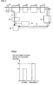
- Fig. 4 is a view showing target SOCs of power storage device 40 for the auxiliary machine.
- the SOC of power storage device 40 for the auxiliary machine is controlled to S1.
- the SOC of power storage device 40 for the auxiliary machine is controlled to S2, which is higher than S1, to allow more power to be supplied from power storage device 40 for the auxiliary machine to the outside of the vehicle.
- Figs. 5 and 6 are views for comparatively illustrating external charging times.
- Fig. 5 shows comparison of external charging times when the SOC of main power storage device 12 before external charging is relatively high
- Fig. 6 shows comparison of external charging times when the SOC of main power storage device 12 before external charging is decreased.
- a charging time T3 in a normal situation is substantially equivalent to the charging time for charging main power storage device 12. Since the SOC of main power storage device 12 is relatively high, charging time T3 is not so long.
- path A is selected in an emergency, the charging time for charging power storage device 40 for the auxiliary machine by sub DC-DC converter 36 is longer than the charging time for charging main power storage device 12, and a charging time T1 (>T3) is obtained.
- path B is selected, power storage device 40 for the auxiliary machine is charged using main DC-DC converter 22 having a power rating higher than that of sub DC-DC converter 36, and thus a charging time T2 ( ⁇ T1) is obtained. Therefore, in such a case, path B is selected.
- a charging time T3 in a normal situation is substantially equivalent to the charging time for charging main power storage device 12. Since the SOC of main power storage device 12 before external charging is decreased, charging time T4 is longer. Accordingly, even when path A is selected in an emergency, the charging time for charging power storage device 40 for the auxiliary machine by sub DC-DC converter 36 is shorter than the charging time for charging main power storage device 12, and charging time T4 is also obtained in this case.
- a charging time T5 is longer than T4 by the amount corresponding to charging of power storage device 40 for the auxiliary machine by main DC-DC converter 22. Therefore, in such a case, path A is selected.
- Fig. 7 is a flowchart for illustrating a processing procedure for charging power storage device 40 for the auxiliary machine during external charging.
- charging/discharging ECU 42 determines whether or not an emergency charging flag is ON (step S10).
- the emergency charging flag is a flag which is turned on when the above "emergency" is recognized.
- the emergency charging flag may be received from the outside of the vehicle by a communication device not shown, or may be able to be input by the user of the vehicle through a switch or the like.
- charging/discharging ECU 42 raises a charging target of power storage device 40 for the auxiliary machine (step S20). For example, charging/discharging ECU 42 raises a target SOC indicating a target of the SOC of power storage device 40 for the auxiliary machine, or a target voltage indicating a target of the voltage of power storage device 40 for the auxiliary machine, to be higher than usual.
- charging/discharging ECU 42 calculates a charging time t1 for charging power storage device 40 for the auxiliary machine by sub DC-DC converter 36 (step S40).
- charging/discharging ECU 42 can calculate the SOC of power storage device 40 for the auxiliary machine based on voltage VB2 and/or current IB2 of power storage device 40 for the auxiliary machine, and calculate charging time t1 based on a difference between the calculated SOC and the target SOC, and power (W) which can be supplied from sub DC-DC converter 36 to power storage device 40 for the auxiliary machine.
- charging/discharging ECU 42 calculates a charging time t2 for charging main power storage device 12 (step S50). For example, charging/discharging ECU 42 can calculate the SOC of main power storage device 12 based on voltage VB1 and/or current IB1 of main power storage device 12, and calculate charging time t2 based on a difference between the calculated SOC and a target SOC of main power storage device 12, and power (W) which can be supplied from bidirectional converter 32 to main power storage device 12.
- charging/discharging ECU 42 determines whether or not charging time t1 calculated in step S40 is longer than charging time t2 calculated in step S50 (step S60).
- charging time t1 is longer than charging time t2 (YES in step S60)
- charging/discharging ECU 42 actuates main DC-DC converter 22 and stops sub DC-DC converter 36 (step S70). That is, path B is selected as a charging route for charging power storage device 40 for the auxiliary machine.
- charging/discharging ECU 42 determines whether or not charging of power storage device 40 for the auxiliary machine by main DC-DC converter 22 has been completed (step S80).
- the processing proceeds to step S110, and when it is determined that the charging of power storage device 40 for the auxiliary machine has not been completed (NO in step S80), the processing goes back to step S70.
- step S60 when it is determined in step S60 that charging time t1 is not more than charging time t2 (NO in step S60), i.e., when it is determined that the charging time for charging power storage device 40 for the auxiliary machine through path A is not more than the charging time for charging main power storage device 12, charging/discharging ECU 42 actuates sub DC-DC converter 36 and stops main DC-DC converter 22 (step S90). That is, path A is selected as a charging route for charging power storage device 40 for the auxiliary machine.
- charging/discharging ECU 42 determines whether or not charging of power storage device 40 for the auxiliary machine by sub DC-DC converter 36 has been completed (step S100).
- the processing proceeds to step S110, and when it is determined that the charging of power storage device 40 for the auxiliary machine has not been completed (NO in step S100), the processing goes back to step S90.
- step S10 when it is determined in step S10 that the emergency charging flag is OFF (NO in step S10), charging/discharging ECU 42 performs usual external charging (step S20). That is, charging/discharging ECU 42 does not raise the charging target of power storage device 40 for the auxiliary machine, and operates sub DC-DC converter 36 to generate operating power for auxiliary machine 38 by sub DC-DC converter 36 (main DC-DC converter 22 is stopped).
- Embodiment 1 when external charging is performed in an emergency, power storage device 40 for the auxiliary machine (main power storage device 12 may also be included) is charged more than usual. Therefore, according to Embodiment 1, power or a power amount which is greater than usual can be supplied to the outside of the vehicle in an emergency.
- Embodiment 1 when external charging is performed in an emergency, the charging path for charging power storage device 40 for the auxiliary machine can be switched between path A using sub DC-DC converter 36 and path B using main DC-DC converter 22. Therefore, according to Embodiment 1, external charging can be efficiently performed by switching between paths A and B depending on efficiency during external charging.
- Embodiment 1 when the charging time for charging power storage device 40 for the auxiliary machine through path A is longer than the charging time for charging main power storage device 12, power storage device 40 for the auxiliary machine is charged through path B.
- the charging time for charging power storage device 40 for the auxiliary machine through path A is not more than the charging time for charging main power storage device 12, power storage device 40 for the auxiliary machine is charged through path A. Therefore, according to Embodiment 1, an increase in the charging time due to an increase in the charging amount of power storage device 40 for the auxiliary machine in an emergency can be suppressed.
- the charging amount of power storage device 40 for the auxiliary machine is controlled to become greater than usual to ensure more power (W) or power amount (Wh) which can be externally discharged, and the charging path for charging power storage device 40 for the auxiliary machine can be switched between paths A and B to suppress an increase in the charging time due to an increase in the charging amount.
- an input unit is provided which allows the user to instruct that more power or power amount which can be externally discharged be ensured regardless of whether or not the situation is in an "emergency", and the charging target of power storage device 40 for the auxiliary machine is raised based on an input through the input unit. It is noted that selection of the charging path (path A or B) when the charging target of power storage device 40 for the auxiliary machine is raised is identical to that in Embodiment 1.
- Fig. 8 is an overall configuration diagram of a vehicle equipped with a power supply system in accordance with Embodiment 2.
- a vehicle 10A further includes an input unit 44, and includes a charging/discharging ECU 42A instead of charging/discharging ECU 42, in the configuration of vehicle 10 in Embodiment 1 shown in Fig. 1 .
- Input unit 44 is a manipulation switch for allowing the user to request that power or a power amount to be output to the outside of the vehicle when external discharging is performed be greater than usual. If input unit 44 is turned on by the user when external charging is performed, charging/discharging ECU 42A raises the charging target (target SOC or target voltage) of power storage device 40 for the auxiliary machine. It is noted that other functions of charging/discharging ECU 42A are identical to those of charging/discharging ECU 42 in Embodiment 1 shown in Fig. 1 .
- Embodiment 2 more power or power amount which can be externally discharged can be ensured upon the user's request. Further, according to Embodiment 2, external charging can be efficiently performed by switching between paths A and B depending on efficiency during external charging, and an increase in the charging time due to an increase in the charging amount of power storage device 40 for the auxiliary machine upon the user's request can be suppressed, as in Embodiment 1.
- main power storage device 12 corresponds to one embodiment of a "first power storage device” in the present invention
- power storage device 40 for the auxiliary machine corresponds to one embodiment of a "second power storage device” in the present invention.
- bidirectional converter 32 corresponds to one embodiment of a "first power conversion device” in the present invention
- sub DC-DC converter 36 corresponds to one embodiment of a "second power conversion device” in the present invention.
- main DC-DC converter 22 corresponds to one embodiment of a "third power conversion device” in the present invention
- charging/discharging ECU 42, 42A corresponds to one embodiment of a "control device” in the present invention.
- input unit 44 corresponds to one embodiment of an "input manipulation unit” in the present invention.
- 10, 10A vehicle; 12: main power storage device; 14: SMR; 16: PCU; 18: motive power output device ; 20: drive wheels; 22: main DC-DC converter; 24: MG-ECU; 30: power supplying/receiving unit; 32: bidirectional converter; 34: charging relay; 36: sub DC-DC converter; 38: auxiliary machine; 40: power storage device for auxiliary machine; 42, 42A: charging/discharging ECU; 44: input unit; 52, 54, 58: conversion unit; 56: insulation transformer; PL: positive electrode line; NL: negative electrode line.
Landscapes
- Engineering & Computer Science (AREA)
- Power Engineering (AREA)
- Transportation (AREA)
- Mechanical Engineering (AREA)
- Life Sciences & Earth Sciences (AREA)
- Sustainable Development (AREA)
- Sustainable Energy (AREA)
- Charge And Discharge Circuits For Batteries Or The Like (AREA)
- Electric Propulsion And Braking For Vehicles (AREA)
- Supply And Distribution Of Alternating Current (AREA)
Abstract
Description
- The present invention relates to a power supply system, a vehicle equipped with the same, and a control method for the power supply system, and in particular to a power supply system which is mounted in a vehicle and can supply and receive electric power to and from the outside of the vehicle, the vehicle equipped with the same, and a control method for the power supply system.
- In recent years, electric vehicles, hybrid vehicles, and the like have received attention as environment-friendly vehicles. These vehicles are equipped with a motor generating a traveling drive force, and a power storage device storing electric power to be supplied to the motor. A hybrid vehicle is a vehicle equipped with an internal combustion engine and a motor serving as motive power sources.
- In such vehicles, a vehicle including a power storage device which can be charged by a power supply outside the vehicle (hereinafter also referred to as an "external power supply", and charging of a power storage device by an external power supply will be also referred to as "external charging") has been known. For example, electric power is supplied from a general household power supply to the power storage device by connecting a power outlet provided in a house and a charging inlet provided in the vehicle using a charging cable.
- On the other hand, a vehicle which can supply electric power stored in a vehicle-mounted power storage device to an external power supply or an electric load outside the vehicle has also been known (hereinafter, power feeding from a power storage device to an external power supply or an electric load outside a vehicle will also be referred to as "external discharging"). For example, Japanese Patent Laying-Open No.
2010-35277 -
- PTD 1: Japanese Patent Laying-Open No.
2010-35277 - PTD 2: Japanese Patent Laying-Open No.
2009-148070 - PTD 3: International Publication No.
2011/024285 - For a vehicle which can charge a vehicle-mounted power storage device using an external power supply and which can supply electric power stored in the vehicle-mounted power storage device to the external power supply or an electric load outside the vehicle, it is a problem to be able to output power (W) or a power amount (Wh) to the outside of the vehicle, in an emergency such as when a commercial system power supply fails, or upon a user's request, so as to be greater than usual (i.e., other than in an emergency, or when there is no user's request). Such a problem and concrete means for solving the problem are not particularly considered in
Patent Document 1. - Accordingly, one object of the present invention is to be able to output, in a power supply system which can supply and receive electric power to and from the outside of a vehicle and the vehicle equipped with the same, power or a power amount which is greater than usual to the outside of the vehicle, in an emergency or upon a user's request.
- Further, another object of the present invention is to be able to output, in a control method for a power supply system which can supply and receive electric power to and from the outside of a vehicle, power or a power amount which is greater than usual to the outside of the vehicle, in an emergency or upon a user's request.
- According to the present invention, provided is a power supply system mounted in a vehicle, including a chargeable/dischargeable power storage unit and a power conversion unit. The power conversion unit selectively performs first power conversion converting power supplied from outside of the vehicle into charging power for the power storage unit, and second power conversion converting power stored in the power storage unit into output power to the outside of the vehicle. When charging of the power storage unit from the outside of the vehicle is performed by the power conversion unit in a predetermined situation where power or a power amount to be output to the outside of the vehicle when the second power conversion is performed is requested to be greater than usual, the power conversion unit performs the first power conversion such that a state quantity indicating a state of charge of the power storage unit becomes greater than usual.
- Preferably, the power storage unit includes first and second power storage devices. The first power storage device stores power for traveling. The second power storage device stores power for an auxiliary machine. When the charging of the power storage unit is performed by the power conversion unit in the predetermined situation, the power conversion unit performs the first power conversion such that a state quantity indicating a state of charge of the second power storage device becomes greater than usual.
- More preferably, the power conversion unit includes first to third power conversion devices. The first power conversion device selectively performs third power conversion converting the power supplied from the outside of the vehicle into charging power for the first power storage device, and fourth power conversion converting power stored in the first power storage device into the output power to the outside of the vehicle. The second power conversion device selectively performs fifth power conversion converting the power supplied from the outside of the vehicle into charging power for the second power storage device, and sixth power conversion converting power stored in the second power storage device into the output power to the outside of the vehicle. The third power conversion device converts the power stored in the first power storage device into the power for the auxiliary machine. The second power conversion device has a power rating lower than that of the third power conversion device. The power supply system further includes a control device controlling the first to third power conversion devices. When the charging of the power storage unit is performed by the power conversion unit in the predetermined situation, the control device switches between a first charging path for charging the second power storage device using the second power conversion device and a second charging path for charging the second power storage device using the first and third power conversion devices, depending on efficiency during the charging of the power storage unit from the outside of the vehicle.
- More preferably, the control device calculates a first charging time indicating a charging time for charging the first power storage device by the first power conversion device, and a second charging time indicating a charging time for charging the second power storage device by the second power conversion device, and when the first charging time is longer than the second charging time, the control device selects the first charging path, and when the second charging time is longer than the first charging time, the control device selects the second charging path.
- Preferably, the predetermined situation is a situation during a power failure of a commercial system power supply to which an electric load receiving the power output from the vehicle when the second power conversion is performed is connected.
- Preferably, the power supply system further includes an input manipulation unit. The input manipulation unit allows a user to request that the power or the power amount to be output to the outside of the vehicle when the second power conversion is performed be greater than usual. The predetermined situation is a situation where the input manipulation unit is manipulated by the user.
- Further, according to the present invention, provided is a vehicle including any power supply system described above.
- Furthermore, according to the present invention, provided is a control method for a power supply system mounted in a vehicle. The power supply system includes a chargeable/dischargeable power storage unit and a power conversion unit. The power conversion unit selectively performs first power conversion converting power supplied from outside of the vehicle into charging power for the power storage unit, and second power conversion converting power stored in the power storage unit into output power to the outside of the vehicle. The control method includes the steps of: determining whether or not there arises a predetermined situation where power or a power amount to be output to the outside of the vehicle when the second power conversion is performed is requested to be greater than usual; determining whether or not charging of the power storage unit from the outside of the vehicle is performed by the power conversion unit; and, when the charging of the power storage unit is performed by the power conversion unit in the predetermined situation, performing the first power conversion such that a state quantity indicating a state of charge of the power storage unit becomes greater than usual.
- Preferably, the power storage unit includes first and second power storage devices. The first power storage device stores power for traveling. The second power storage device stores power for an auxiliary machine. The step of performing the first power conversion includes the step of performing the first power conversion, when the charging of the power storage unit is performed by the power conversion unit in the predetermined situation, such that a state quantity indicating a state of charge of the second power storage device becomes greater than usual.
- More preferably, the power conversion unit includes first to third power conversion devices. The first power conversion device selectively performs third power conversion converting the power supplied from the outside of the vehicle into charging power for the first power storage device, and fourth power conversion converting power stored in the first power storage device into the output power to the outside of the vehicle. The second power conversion device selectively performs fifth power conversion converting the power supplied from the outside of the vehicle into charging power for the second power storage device, and sixth power conversion converting power stored in the second power storage device into the output power to the outside of the vehicle. The third power conversion device converts the power stored in the first power storage device into the power for the auxiliary machine. The second power conversion device has a power rating lower than that of the third power conversion device. The control method further includes the step of switching, when the charging of the power storage unit is performed by the power conversion unit in the predetermined situation, between a first charging path for charging the second power storage device using the second power conversion device and a second charging path for charging the second power storage device using the first and third power conversion devices, depending on efficiency during the charging of the power storage unit from the outside of the vehicle.
- In the present invention, the power storage unit is charged more than usual when charging of the power storage unit from the outside of the vehicle is performed by the power conversion unit in a predetermined situation where power or a power amount to be output to the outside of the vehicle is requested to be greater than usual. Therefore, according to the present invention, power or a power amount which is greater than usual can be output to the outside of the vehicle in the predetermined situation.
-
-
Fig. 1 is an overall configuration diagram of a vehicle equipped with a power supply system in accordance withEmbodiment 1 of the present invention. -
Fig. 2 is a circuit diagram of a bidirectional converter shown inFig. 1 . -
Fig. 3 is a view showing charging paths for charging a power storage device for an auxiliary machine during external charging. -
Fig. 4 is a view showing target SOCs of the power storage device for the auxiliary machine. -
Fig. 5 is a first view for comparatively illustrating external charging times. -
Fig. 6 is a second view for comparatively illustrating external charging times. -
Fig. 7 is a flowchart for illustrating a processing procedure for charging the power storage device for the auxiliary machine during external charging. -
Fig. 8 is an overall configuration diagram of a vehicle equipped with a power supply system in accordance with Embodiment 2. - Hereinafter, embodiments of the present invention will be described in detail with reference to the drawings, in which identical or corresponding parts will be designated by the same reference numerals, and the description thereof will not be repeated.
-
Fig. 1 is an overall configuration diagram of a vehicle equipped with a power supply system in accordance withEmbodiment 1 of the present invention. Referring toFig. 1 , avehicle 10 includes a mainpower storage device 12, a system main relay (hereinafter referred to as an "SMR") 14, a power control unit (hereinafter referred to as a "PCU") 16, a motivepower output device 18,drive wheels 20, a main DC-DC converter 22, and an MG-ECU (Electronic Control Unit) 24. - Main
power storage device 12 stores power for traveling. Mainpower storage device 12 is a chargeable/dischargeable direct-current (DC) power supply, and is composed of, for example, a secondary battery such as a nickel hydride battery and a lithium ion battery. In mainpower storage device 12, power supplied from an external power supply (not shown) and power generated in motivepower output device 18 are stored. It is noted that a large-capacity capacitor can also be employed as mainpower storage device 12.SMR 14 is provided between mainpower storage device 12 andPCU 16.SMR 14 is a relay for establishing electrical connection/disconnection between mainpower storage device 12 andPCU 16. -
PCU 16 collectively refers to power conversion devices for receiving power from mainpower storage device 12 to drive motivepower output device 18. For example,PCU 16 includes an inverter for driving a motor included in motivepower output device 18, a converter boosting the power output from mainpower storage device 12, and the like. Motivepower output device 18 collectively refers to devices for drivingdrive wheels 20. For example, motivepower output device 18 includes the motor, an engine, and the like drivingdrive wheels 20. Further, motivepower output device 18 generates electric power by the motor drivingdrive wheels 20 during braking of the vehicle and the like, and outputs the generated electric power toPCU 16. - Main DC-
DC converter 22 is connected to a power line betweenSMR 14 andPCU 16. Main DC-DC converter 22 is provided to generate electric power for an auxiliary machine while the vehicle is traveling (including the case where the vehicle stops to wait for a traffic light, and the like). In accordance with a control command from MG-ECU 24, main DC-DC converter 22 converts power received from mainpower storage device 12 orPCU 16 into the power for the auxiliary machine, and outputs it to anauxiliary machine 38 and apower storage device 40 for the auxiliary machine (described later). It is noted that, inEmbodiment 1, depending on circumstances, main DC-DC converter 22 can also operate during external charging, as described later. - MG-
ECU 24controls PCU 16 which drives motivepower output device 18, by software processing performed by executing a prestored program by a central processing unit (CPU) and/or hardware processing performed by a dedicated electronic circuit. Further, when a remaining capacity ofpower storage device 40 for the auxiliary machine is decreased while the vehicle is traveling (including the case where the vehicle stops to wait for a traffic light, and the like), MG-ECU 24 controls main DC-DC converter 22 to chargepower storage device 40 for the auxiliary machine by main DC-DC converter 22. -
Vehicle 10 further includes a power supplying/receivingunit 30, abidirectional converter 32, a chargingrelay 34, a sub DC-DC converter 36,auxiliary machine 38,power storage device 40 for the auxiliary machine, and a charging/dischargingECU 42. - Power supplying/receiving
unit 30 receives power supplied from an external power supply or an electric load outside the vehicle not shown (hereinafter also collectively referred to as "external power supply and the like") during external charging, and outputs power stored in mainpower storage device 12 and/orpower storage device 40 for the auxiliary machine to the external power supply and the like during external discharging. Power supplying/receivingunit 30 may be configured to supply and receive power to and from the external power supply and the like by being connected to a power cable connected to the external power supply and the like, or may be configured to supply and receive power to and from the external power supply and the like in a non-contact manner using a non-contact power transmission technique such as electromagnetic induction or a so-called resonance method. -
Bidirectional converter 32 is provided between power supplying/receivingunit 30 and mainpower storage device 12. Chargingrelay 34 is further provided betweenbidirectional converter 32 and mainpower storage device 12. During external charging, in accordance with a control command from charging/dischargingECU 42,bidirectional converter 32 converts the power supplied from the external power supply and input from power supplying/receivingunit 30 into charging power for mainpower storage device 12, and outputs the converted power to mainpower storage device 12. Further, sub DC-DC converter 36 is connected tobidirectional converter 32. During external charging,bidirectional converter 32 outputs the power received by power supplying/receivingunit 30 to sub DC-DC converter 36. It is noted that a configuration of connection betweenbidirectional converter 32 and sub DC-DC converter 36 will be described later with reference to a circuit diagram. - In addition, during external discharging, in accordance with a control command from charging/discharging
ECU 42,bidirectional converter 32 converts the power stored in mainpower storage device 12 and power received from sub DC-DC converter 36 into output power to the external power supply and the like, and outputs the converted power to power supplying/receivingunit 30. In accordance with a control command from charging/dischargingECU 42, chargingrelay 34 establishes electrical connection/disconnection betweenbidirectional converter 32 and mainpower storage device 12. - Sub DC-
DC converter 36 is connected tobidirectional converter 32. Sub DC-DC converter 36 is provided to generate power for the auxiliary machine during external charging. When sub DC-DC converter 36 receives a control command from charging/dischargingECU 42 during external charging, sub DC-DC converter 36 converts the power received frombidirectional converter 32 into the power for the auxiliary machine, and outputs it toauxiliary machine 38 andpower storage device 40 for the auxiliary machine. Further, during external discharging, in accordance with a control command from charging/dischargingECU 42, sub DC-DC converter 36 converts power stored inpower storage device 40 for the auxiliary machine into power to be output from power supplying/receivingunit 30 to the external power supply and the like, and outputs the converted power tobidirectional converter 32. -
Auxiliary machine 38 collectively refers to auxiliary machines mounted invehicle 10.Auxiliary machine 38 operates upon receiving supply of power frompower storage device 40 for the auxiliary machine. Further, while sub DC-DC converter 36 is operating during external charging,auxiliary machine 38 operates upon receiving supply of power from sub DC-DC converter 36. It is noted thatauxiliary machine 38 has different magnitudes of loads during traveling and during external charging and external discharging (hereinafter also referred to as "during external charging/discharging"), that is,auxiliary machine 38 has a high load during traveling, and has a low load during external charging/discharging (because auxiliary machines to be operated are limited). Thus, the power rating of sub DC-DC converter 36 is designed to have a value lower than that of main DC-DC converter 22. -
Power storage device 40 for the auxiliary machine stores operating power forauxiliary machine 38, MG-ECU 24, charging/dischargingECU 42, and the like.Power storage device 40 for the auxiliary machine is a chargeable/dischargeable DC power supply, and is composed of, for example, a secondary battery such as a lithium ion battery, a nickel hydride battery, and a lead battery. - Charging/discharging
ECU 42 controls external charging and external discharging, by software processing performed by executing a prestored program by a CPU and/or hardware processing performed by a dedicated electronic circuit. Specifically, charging/dischargingECU 42 calculates a remaining capacity (SOC) of mainpower storage device 12 using a voltage VB1 and/or a current IB1 of mainpower storage device 12, and calculates an SOC ofpower storage device 40 for the auxiliary machine using a voltage VB2 and/or a current IB2 ofpower storage device 40 for the auxiliary machine. It is noted that various known methods can be used to calculate the SOC. Further, the voltage and the current of each of mainpower storage device 12 andpower storage device 40 for the auxiliary machine are detected by a voltage sensor and a current sensor not shown. - During external charging, charging/discharging
ECU 42 generates a control signal for drivingbidirectional converter 32 to convert the power input from power supplying/receivingunit 30 into the charging power for the main power storage device, based on the SOC of mainpower storage device 12, and outputs the generated control signal tobidirectional converter 32. Further, during external charging, charging/dischargingECU 42 generates a control signal for driving sub DC-DC converter 36 as necessary, and outputs the generated control signal to sub DC-DC converter 36. - Here, when external charging is performed in a predetermined emergency, charging/discharging
ECU 42 controls sub DC-DC converter 36 or main DC-DC converter 22 such that the SOC ofpower storage device 40 for the auxiliary machine becomes greater than usual, to ensure more power (W) or power amount (Wh) which can be externally discharged fromvehicle 10. Here, an "emergency" refers to a situation where a commercial system power supply fails or a power failure thereof is expected, and more specifically, where a commercial system power supply connected to an electric load receiving supply of power from power supplying/receivingunit 30 during external discharging fails, or a power failure thereof is expected. Examples of the situation where external charging is performed in an emergency include, but are not limited to, a situation where external charging is performed when a power failure of a commercial system power supply is scheduled (i.e., in an emergency), and a situation where, when a commercial system power supply in a region fails (i.e., in an emergency), external charging is performed at a charging station and the like in a region other than the region where power fails. In addition, "usual" described above refers to not being in the above "emergency". - Although it has been described above to set the SOC of
power storage device 40 for the auxiliary machine to be greater than usual when external charging is performed in an emergency, to ensure more power (W) or power amount (Wh) which can be externally discharged, the SOC of mainpower storage device 12 may be set to be greater than usual. However, since mainpower storage device 12 is charged to a high SOC also in usual external charging, mainpower storage device 12 has little room for further charging, and thus it is preferable to chargepower storage device 40 for the auxiliary machine, which has room for charging greater than that of mainpower storage device 12. Further, although it has been described above to set the SOC ofpower storage device 40 for the auxiliary machine to be greater than usual, voltage VB2 ofpower storage device 40 for the auxiliary machine may be set to be greater than usual, instead of the SOC thereof. - In addition, in
Embodiment 1, when external charging is performed in an emergency, a charging path for chargingpower storage device 40 for the auxiliary machine can be switched between a charging path using sub DC-DC converter 36 and a charging path using main DC-DC converter 22. Which charging path is to be used to chargepower storage device 40 for the auxiliary machine is determined based on efficiency during charging ofpower storage device 40 for the auxiliary machine. Namely, as described above, sub DC-DC converter 36 has a power rating lower than that of main DC-DC converter 22, and higher power conversion efficiency is obtained when sub DC-DC converter 36 is used to generate power forauxiliary machine 38 andpower storage device 40 for the auxiliary machine during external charging. However, sincepower storage device 40 for the auxiliary machine is charged such that the SOC thereof becomes greater than usual when external charging is performed in an emergency, ifpower storage device 40 for the auxiliary machine is charged using sub DC-DC converter 36 having a lower power rating, a charging time may be considerably increased. - Thus, in
Embodiment 1, when external charging is performed in an emergency, a charging time for chargingpower storage device 40 for the auxiliary machine by sub DC-DC converter 36 is compared with a charging time for charging mainpower storage device 12, and when the charging time for chargingpower storage device 40 for the auxiliary machine is longer than the charging time for charging mainpower storage device 12, main DC-DC converter 22 having a higher power rating is operated (sub DC-DC converter 36 is stopped), andpower storage device 40 for the auxiliary machine is charged by main DC-DC converter 22. This can prevent an increase in an external charging time due to an increase in the charging time for chargingpower storage device 40 for the auxiliary machine by sub DC-DC converter 36 when external charging is performed in an emergency. - On the other hand, when the charging time for charging
power storage device 40 for the auxiliary machine is not more than the charging time for charging mainpower storage device 12 when external charging is performed in an emergency,power storage device 40 for the auxiliary machine is charged by sub DC-DC converter 36 (without operating main DC-DC converter 22). Thereby,power storage device 40 for the auxiliary machine can be charged using sub DC-DC converter 36, which has relatively higher power conversion efficiency than that of main DC-DC converter 22 during external charging. -
Fig. 2 is a circuit diagram ofbidirectional converter 32 shown inFig. 1 . Referring toFig. 2 ,bidirectional converter 32 includesconversion units insulation transformer 56. Each ofconversion units -
Conversion unit 52 converts alternating current (AC) power from the external power supply input from power supplying/receivingunit 30 into DC power, and outputs it to a positive electrode line PL and a negative electrode line NL, based on a control signal from charging/discharging ECU 42 (Fig. 1 ).Conversion unit 52 can also convert DC power received from positive electrode line PL and negative electrode line NL into AC power, and output it to power supplying/receivingunit 30.Conversion unit 54 converts the DC power received fromconversion unit 52 into AC power and outputs it toinsulation transformer 56, based on a control signal from charging/dischargingECU 42.Conversion unit 54 can also convert AC power received frominsulation transformer 56 into DC power and output it toconversion unit 52. -
Insulation transformer 56 includes a core made of a magnetic material, and a primary coil and a secondary coil wound around the core. The primary coil and the secondary coil are electrically insulated, and are connected toconversion units Insulation transformer 56 converts the AC power fromconversion unit 54 to have a voltage level corresponding to a turn ratio between the primary coil and the secondary coil, and outputs it toconversion unit 58.Insulation transformer 56 can also convert AC power fromconversion unit 58 to have a voltage level corresponding to a turn ratio between the secondary coil and the primary coil, and output it toconversion unit 54. -
Conversion unit 58 converts the AC power received frominsulation transformer 56 into DC power and outputs it to charging relay 34 (Fig. 1 ), based on a control signal from charging/dischargingECU 42.Conversion unit 58 can also convert DC power supplied from chargingrelay 34 into AC power, and output it toinsulation transformer 56. - Sub DC-DC converter 36 (
Fig. 1 ) is connected to positive electrode line PL and negative electrode line NL provided betweenconversion units DC converter 36 may be connected to an output side of conversion unit 58 (the chargingrelay 34 side). - Referring to
Fig. 1 again, inEmbodiment 1, when external charging is performed in an emergency,power storage device 40 for the auxiliary machine is charged such that the SOC ofpower storage device 40 for the auxiliary machine becomes greater than usual, to ensure more power or power amount which can be subsequently externally discharged. Thereby, the charging time for chargingpower storage device 40 for the auxiliary machine by sub DC-DC converter 36 is increased. However, inEmbodiment 1, the charging path for chargingpower storage device 40 for the auxiliary machine is configured such that it can be switched between the path through sub DC-DC converter 36 (a path A) and the path through main DC-DC converter 22 (a path B). When the charging time for chargingpower storage device 40 for the auxiliary machine by sub DC-DC converter 36 is longer than the charging time for charging mainpower storage device 12,power storage device 40 for the auxiliary machine is charged using main DC-DC converter 22 having a power rating higher than that of sub DC-DC converter 36, in order to shorten the external charging time. -
Fig. 3 is a view showing the charging paths for chargingpower storage device 40 for the auxiliary machine during external charging. Referring toFig. 3 , path A is the charging path through sub DC-DC converter 36. That is, the power supplied from the external power supply (not shown) connected to power supplying/receivingunit 30 is supplied topower storage device 40 for the auxiliary machine, by sequentially passing through power supplying/receivingunit 30,bidirectional converter 32, and sub DC-DC converter 36 connected tobidirectional converter 32. - Path B is the charging path through main DC-
DC converter 22. That is, the power supplied from the external power supply connected to power supplying/receivingunit 30 is supplied topower storage device 40 for the auxiliary machine, by sequentially passing through power supplying/receivingunit 30,bidirectional converter 32, chargingrelay 34, mainpower storage device 12,SMR 14, and main DC-DC converter 22. - Sub DC-
DC converter 36 only needs to generate operating power for the auxiliary machine and the ECU operating during external charging, and sub DC-DC converter 36 has a power rating lower than that of main DC-DC converter 22. Higher power conversion efficiency is obtained when sub DC-DC converter 36 is used to generate power forauxiliary machine 38 andpower storage device 40 for the auxiliary machine during external charging, and path A has higher power conversion efficiency than that of path B. - However, since sub DC-
DC converter 36 has a lower power rating, the charging time for chargingpower storage device 40 for the auxiliary machine through path A is longer than that through path B. When the charging time for chargingpower storage device 40 for the auxiliary machine through path A is not more than the charging time for charging main power storage device 12 (i.e., when the SOC of mainpower storage device 12 before external charging is decreased), the external charging time is not increased by chargingpower storage device 40 for the auxiliary machine. On the other hand, when the charging time for chargingpower storage device 40 for the auxiliary machine through path A is longer than the charging time for charging main power storage device 12 (i.e., when the SOC of mainpower storage device 12 before external charging is not so decreased, and the charging time for charging mainpower storage device 12 is not long), the external charging time is increased by chargingpower storage device 40 for the auxiliary machine. - Thus, in
Embodiment 1, the charging path for chargingpower storage device 40 for the auxiliary machine during external charging can be switched between paths A and B. In addition, when the charging for chargingpower storage device 40 for the auxiliary machine through path A is longer than the charging time for charging mainpower storage device 12 due to an increase in a charging amount ofpower storage device 40 for the auxiliary machine in an emergency, the charging path is switched to path B which uses main DC-DC converter 22 having a power rating higher than that of sub DC-DC converter 36, to chargepower storage device 40 for the auxiliary machine. -
Fig. 4 is a view showing target SOCs ofpower storage device 40 for the auxiliary machine. Referring toFig. 4 , in a usual situation (i.e., in a situation other than the above "emergency"), the SOC ofpower storage device 40 for the auxiliary machine is controlled to S1. On the other hand, in an emergency, the SOC ofpower storage device 40 for the auxiliary machine is controlled to S2, which is higher than S1, to allow more power to be supplied frompower storage device 40 for the auxiliary machine to the outside of the vehicle. -
Figs. 5 and 6 are views for comparatively illustrating external charging times.Fig. 5 shows comparison of external charging times when the SOC of mainpower storage device 12 before external charging is relatively high, andFig. 6 shows comparison of external charging times when the SOC of mainpower storage device 12 before external charging is decreased. - Referring to
Fig. 5 , a charging time T3 in a normal situation is substantially equivalent to the charging time for charging mainpower storage device 12. Since the SOC of mainpower storage device 12 is relatively high, charging time T3 is not so long. When path A is selected in an emergency, the charging time for chargingpower storage device 40 for the auxiliary machine by sub DC-DC converter 36 is longer than the charging time for charging mainpower storage device 12, and a charging time T1 (>T3) is obtained. When path B is selected,power storage device 40 for the auxiliary machine is charged using main DC-DC converter 22 having a power rating higher than that of sub DC-DC converter 36, and thus a charging time T2 (<T1) is obtained. Therefore, in such a case, path B is selected. - Referring to
Fig. 6 , a charging time T3 in a normal situation is substantially equivalent to the charging time for charging mainpower storage device 12. Since the SOC of mainpower storage device 12 before external charging is decreased, charging time T4 is longer. Accordingly, even when path A is selected in an emergency, the charging time for chargingpower storage device 40 for the auxiliary machine by sub DC-DC converter 36 is shorter than the charging time for charging mainpower storage device 12, and charging time T4 is also obtained in this case. When path B is selected, a charging time T5 is longer than T4 by the amount corresponding to charging ofpower storage device 40 for the auxiliary machine by main DC-DC converter 22. Therefore, in such a case, path A is selected. -
Fig. 7 is a flowchart for illustrating a processing procedure for chargingpower storage device 40 for the auxiliary machine during external charging. Referring toFig. 7 , charging/discharging ECU 42 (Fig. 1 ) determines whether or not an emergency charging flag is ON (step S10). The emergency charging flag is a flag which is turned on when the above "emergency" is recognized. For example, the emergency charging flag may be received from the outside of the vehicle by a communication device not shown, or may be able to be input by the user of the vehicle through a switch or the like. - When it is determined in step S10 that the emergency charging flag is ON (YES in step S10), charging/discharging
ECU 42 raises a charging target ofpower storage device 40 for the auxiliary machine (step S20). For example, charging/dischargingECU 42 raises a target SOC indicating a target of the SOC ofpower storage device 40 for the auxiliary machine, or a target voltage indicating a target of the voltage ofpower storage device 40 for the auxiliary machine, to be higher than usual. - Subsequently, charging/discharging
ECU 42 calculates a charging time t1 for chargingpower storage device 40 for the auxiliary machine by sub DC-DC converter 36 (step S40). For example, charging/dischargingECU 42 can calculate the SOC ofpower storage device 40 for the auxiliary machine based on voltage VB2 and/or current IB2 ofpower storage device 40 for the auxiliary machine, and calculate charging time t1 based on a difference between the calculated SOC and the target SOC, and power (W) which can be supplied from sub DC-DC converter 36 topower storage device 40 for the auxiliary machine. - Further, charging/discharging
ECU 42 calculates a charging time t2 for charging main power storage device 12 (step S50). For example, charging/dischargingECU 42 can calculate the SOC of mainpower storage device 12 based on voltage VB1 and/or current IB1 of mainpower storage device 12, and calculate charging time t2 based on a difference between the calculated SOC and a target SOC of mainpower storage device 12, and power (W) which can be supplied frombidirectional converter 32 to mainpower storage device 12. - Then, charging/discharging
ECU 42 determines whether or not charging time t1 calculated in step S40 is longer than charging time t2 calculated in step S50 (step S60). When it is determined that charging time t1 is longer than charging time t2 (YES in step S60), i.e., when it is determined that the charging time for chargingpower storage device 40 for the auxiliary machine through path A is longer than the charging time for charging mainpower storage device 12, charging/dischargingECU 42 actuates main DC-DC converter 22 and stops sub DC-DC converter 36 (step S70). That is, path B is selected as a charging route for chargingpower storage device 40 for the auxiliary machine. - Thereafter, charging/discharging
ECU 42 determines whether or not charging ofpower storage device 40 for the auxiliary machine by main DC-DC converter 22 has been completed (step S80). When it is determined that the charging ofpower storage device 40 for the auxiliary machine has been completed (YES in step S80), the processing proceeds to step S110, and when it is determined that the charging ofpower storage device 40 for the auxiliary machine has not been completed (NO in step S80), the processing goes back to step S70. - On the other hand, when it is determined in step S60 that charging time t1 is not more than charging time t2 (NO in step S60), i.e., when it is determined that the charging time for charging
power storage device 40 for the auxiliary machine through path A is not more than the charging time for charging mainpower storage device 12, charging/dischargingECU 42 actuates sub DC-DC converter 36 and stops main DC-DC converter 22 (step S90). That is, path A is selected as a charging route for chargingpower storage device 40 for the auxiliary machine. - Thereafter, charging/discharging
ECU 42 determines whether or not charging ofpower storage device 40 for the auxiliary machine by sub DC-DC converter 36 has been completed (step S100). When it is determined that the charging ofpower storage device 40 for the auxiliary machine has been completed (YES in step S100), the processing proceeds to step S110, and when it is determined that the charging ofpower storage device 40 for the auxiliary machine has not been completed (NO in step S100), the processing goes back to step S90. - It is noted that, when it is determined in step S10 that the emergency charging flag is OFF (NO in step S10), charging/discharging
ECU 42 performs usual external charging (step S20). That is, charging/dischargingECU 42 does not raise the charging target ofpower storage device 40 for the auxiliary machine, and operates sub DC-DC converter 36 to generate operating power forauxiliary machine 38 by sub DC-DC converter 36 (main DC-DC converter 22 is stopped). - As described above, in
Embodiment 1, when external charging is performed in an emergency,power storage device 40 for the auxiliary machine (mainpower storage device 12 may also be included) is charged more than usual. Therefore, according toEmbodiment 1, power or a power amount which is greater than usual can be supplied to the outside of the vehicle in an emergency. - Further, in
Embodiment 1, when external charging is performed in an emergency, the charging path for chargingpower storage device 40 for the auxiliary machine can be switched between path A using sub DC-DC converter 36 and path B using main DC-DC converter 22. Therefore, according toEmbodiment 1, external charging can be efficiently performed by switching between paths A and B depending on efficiency during external charging. - Furthermore, in
Embodiment 1, when the charging time for chargingpower storage device 40 for the auxiliary machine through path A is longer than the charging time for charging mainpower storage device 12,power storage device 40 for the auxiliary machine is charged through path B. When the charging time for chargingpower storage device 40 for the auxiliary machine through path A is not more than the charging time for charging mainpower storage device 12,power storage device 40 for the auxiliary machine is charged through path A. Therefore, according toEmbodiment 1, an increase in the charging time due to an increase in the charging amount ofpower storage device 40 for the auxiliary machine in an emergency can be suppressed. - In
Embodiment 1 described above, when external charging is performed in an emergency, the charging amount ofpower storage device 40 for the auxiliary machine is controlled to become greater than usual to ensure more power (W) or power amount (Wh) which can be externally discharged, and the charging path for chargingpower storage device 40 for the auxiliary machine can be switched between paths A and B to suppress an increase in the charging time due to an increase in the charging amount. - In Embodiment 2, an input unit is provided which allows the user to instruct that more power or power amount which can be externally discharged be ensured regardless of whether or not the situation is in an "emergency", and the charging target of
power storage device 40 for the auxiliary machine is raised based on an input through the input unit. It is noted that selection of the charging path (path A or B) when the charging target ofpower storage device 40 for the auxiliary machine is raised is identical to that inEmbodiment 1. -
Fig. 8 is an overall configuration diagram of a vehicle equipped with a power supply system in accordance with Embodiment 2. Referring toFig. 8 , avehicle 10A further includes an input unit 44, and includes a charging/dischargingECU 42A instead of charging/dischargingECU 42, in the configuration ofvehicle 10 inEmbodiment 1 shown inFig. 1 . - Input unit 44 is a manipulation switch for allowing the user to request that power or a power amount to be output to the outside of the vehicle when external discharging is performed be greater than usual. If input unit 44 is turned on by the user when external charging is performed, charging/discharging
ECU 42A raises the charging target (target SOC or target voltage) ofpower storage device 40 for the auxiliary machine. It is noted that other functions of charging/dischargingECU 42A are identical to those of charging/dischargingECU 42 inEmbodiment 1 shown inFig. 1 . - As described above, according to Embodiment 2, more power or power amount which can be externally discharged can be ensured upon the user's request. Further, according to Embodiment 2, external charging can be efficiently performed by switching between paths A and B depending on efficiency during external charging, and an increase in the charging time due to an increase in the charging amount of
power storage device 40 for the auxiliary machine upon the user's request can be suppressed, as inEmbodiment 1. - It is noted that, in the above description, main
power storage device 12 corresponds to one embodiment of a "first power storage device" in the present invention, andpower storage device 40 for the auxiliary machine corresponds to one embodiment of a "second power storage device" in the present invention. Further,bidirectional converter 32 corresponds to one embodiment of a "first power conversion device" in the present invention, and sub DC-DC converter 36 corresponds to one embodiment of a "second power conversion device" in the present invention. Furthermore, main DC-DC converter 22 corresponds to one embodiment of a "third power conversion device" in the present invention, and charging/dischargingECU - It should be understood that the embodiments disclosed herein are illustrative and non-restrictive in every respect. The scope of the present invention is defined by the scope of the claims, rather than the above description of the embodiments, and is intended to include any modifications within the scope and meaning equivalent to the scope of the claims.
- 10, 10A: vehicle; 12: main power storage device; 14: SMR; 16: PCU; 18: motive power output device ; 20: drive wheels; 22: main DC-DC converter; 24: MG-ECU; 30: power supplying/receiving unit; 32: bidirectional converter; 34: charging relay; 36: sub DC-DC converter; 38: auxiliary machine; 40: power storage device for auxiliary machine; 42, 42A: charging/discharging ECU; 44: input unit; 52, 54, 58: conversion unit; 56: insulation transformer; PL: positive electrode line; NL: negative electrode line.
Claims (10)
- A power supply system mounted in a vehicle, comprising:a chargeable/dischargeable power storage unit (12, 40); anda power conversion unit (32, 36, 22) selectively performing first power conversion converting power supplied from outside of the vehicle into charging power for said power storage unit, and second power conversion converting power stored in said power storage unit into output power to the outside of the vehicle,when charging of said power storage unit from the outside of the vehicle is performed by said power conversion unit in a predetermined situation where power or a power amount to be output to the outside of the vehicle when said second power conversion is performed is requested to be greater than usual, said power conversion unit performing said first power conversion such that a state quantity indicating a state of charge of said power storage unit becomes greater than usual.
- The power supply system according to claim 1, wherein
said power storage unit includes
a first power storage device (12) storing power for traveling, and
a second power storage device (40) storing power for an auxiliary machine, and
when the charging of said power storage unit is performed by said power conversion unit in said predetermined situation, said power conversion unit performs said first power conversion such that a state quantity indicating a state of charge of said second power storage device becomes greater than usual. - The power supply system according to claim 2, wherein
said power conversion unit includes
a first power conversion device (32) selectively performing third power conversion converting the power supplied from the outside of the vehicle into charging power for said first power storage device, and fourth power conversion converting power stored in said first power storage device into the output power to the outside of the vehicle,
a second power conversion device (36) selectively performing fifth power conversion converting the power supplied from the outside of the vehicle into charging power for said second power storage device, and sixth power conversion converting power stored in said second power storage device into the output power to the outside of the vehicle, and
a third power conversion device (22) converting the power stored in said first power storage device into the power for said auxiliary machine,
said second power conversion device has a power rating lower than that of said third power conversion device,
said power supply system further comprises a control device (42, 42A) controlling said first to third power conversion devices, and
when the charging of said power storage unit is performed by said power conversion unit in said predetermined situation, said control device switches between a first charging path for charging said second power storage device using said second power conversion device and a second charging path for charging said second power storage device using said first and third power conversion devices, depending on efficiency during the charging of said power storage unit from the outside of the vehicle. - The power supply system according to claim 3, wherein
said control device calculates a first charging time indicating a charging time for charging said first power storage device by said first power conversion device, and a second charging time indicating a charging time for charging said second power storage device by said second power conversion device, and
when said first charging time is longer than said second charging time, said control device selects said first charging path, and when said second charging time is longer than said first charging time, said control device selects said second charging path. - The power supply system according to claim 1, wherein said predetermined situation is a situation during a power failure of a commercial system power supply to which an electric load receiving the power output from said vehicle when said second power conversion is performed is connected.
- The power supply system according to claim 1, further comprising an input manipulation unit (44) for allowing a user to request that the power or the power amount to be output to the outside of the vehicle when said second power conversion is performed be greater than usual,
wherein said predetermined situation is a situation where said input manipulation unit is manipulated by the user. - A vehicle comprising the power supply system according to any of claims 1 to 6.
- A control method for a power supply system mounted in a vehicle,
said power supply system including
a chargeable/dischargeable power storage unit (12, 40), and
a power conversion unit (32, 36, 22) selectively performing first power conversion converting power supplied from outside of the vehicle into charging power for said power storage unit, and second power conversion converting power stored in said power storage unit into output power to the outside of the vehicle,
said control method comprising the steps of:determining whether or not there arises a predetermined situation where power or a power amount to be output to the outside of the vehicle when said second power conversion is performed is requested to be greater than usual;determining whether or not charging of said power storage unit from the outside of the vehicle is performed by said power conversion unit; andwhen the charging of said power storage unit is performed by said power conversion unit in said predetermined situation, performing said first power conversion such that a state quantity indicating a state of charge of said power storage unit becomes greater than usual. - The control method for the power supply system according to claim 8,
wherein
said power storage unit includes
a first power storage device (12) storing power for traveling, and
a second power storage device (40) storing power for an auxiliary machine, and
the step of performing said first power conversion includes the step of performing said first power conversion, when the charging of said power storage unit is performed by said power conversion unit in said predetermined situation, such that a state quantity indicating a state of charge of said second power storage device becomes greater than usual. - The control method for the power supply system according to claim 9,
wherein
said power conversion unit includes
a first power conversion device (32) selectively performing third power conversion converting the power supplied from the outside of the vehicle into charging power for said first power storage device, and fourth power conversion converting power stored in said first power storage device into the output power to the outside of the vehicle,
a second power conversion device (36) selectively performing fifth power conversion converting the power supplied from the outside of the vehicle into charging power for said second power storage device, and sixth power conversion converting power stored in said second power storage device into the output power to the outside of the vehicle, and
a third power conversion device (22) converting the power stored in said first power storage device into the power for said auxiliary machine,
said second power conversion device has a power rating lower than that of said third power conversion device,
said control method further comprises the step of switching, when the charging of said power storage unit is performed by said power conversion unit in said predetermined situation, between a first charging path for charging said second power storage device using said second power conversion device and a second charging path for charging said second power storage device using said first and third power conversion devices, depending on efficiency during the charging of said power storage unit from the outside of the vehicle.
Applications Claiming Priority (1)
| Application Number | Priority Date | Filing Date | Title |
|---|---|---|---|
| PCT/JP2011/075420 WO2013065169A1 (en) | 2011-11-04 | 2011-11-04 | Power source system and vehicle provided therewith, and method of controlling power source system |
Publications (3)
| Publication Number | Publication Date |
|---|---|
| EP2774797A1 true EP2774797A1 (en) | 2014-09-10 |
| EP2774797A4 EP2774797A4 (en) | 2016-04-13 |
| EP2774797B1 EP2774797B1 (en) | 2019-05-15 |
Family
ID=48191560
Family Applications (1)
| Application Number | Title | Priority Date | Filing Date |
|---|---|---|---|
| EP11875036.3A Active EP2774797B1 (en) | 2011-11-04 | 2011-11-04 | Power source system and vehicle provided therewith, and method of controlling power source system |
Country Status (6)
| Country | Link |
|---|---|
| US (1) | US9493081B2 (en) |
| EP (1) | EP2774797B1 (en) |
| JP (1) | JP5817837B2 (en) |
| CN (1) | CN104024030B (en) |
| CA (1) | CA2850454C (en) |
| WO (1) | WO2013065169A1 (en) |
Cited By (2)
| Publication number | Priority date | Publication date | Assignee | Title |
|---|---|---|---|---|
| CN105406519A (en) * | 2015-12-18 | 2016-03-16 | 河海大学 | Construction method and operation method of active power distribution network |
| EP3492299A4 (en) * | 2016-07-28 | 2019-07-24 | BYD Company Limited | ELECTRIC CAR, MULTIFUNCTIONAL CHARGER ON BOARD ELECTRIC CAR AND METHOD FOR CONTROLLING THE SAME ELECTRIC VEHICLE |
Families Citing this family (10)
| Publication number | Priority date | Publication date | Assignee | Title |
|---|---|---|---|---|
| US10160410B2 (en) * | 2013-07-12 | 2018-12-25 | Ford Global Technologies, Llc | System and method for supplying auxiliary power to an electrified vehicle |
| US9656563B2 (en) * | 2014-07-31 | 2017-05-23 | Toyota Motor Engineering & Manufacturing North America, Inc. | Modular wireless electrical system |
| US10252618B2 (en) * | 2016-09-06 | 2019-04-09 | Ford Global Technologies, Llc | Backup electrical supply for main capacitor discharge |
| CN108092371B (en) * | 2016-11-15 | 2020-04-03 | 华为技术有限公司 | Charge and discharge device |
| WO2019111872A1 (en) * | 2017-12-04 | 2019-06-13 | 株式会社Gsユアサ | Charging control device, electricity storage device, and charging method |
| DE102018203263A1 (en) * | 2018-03-06 | 2019-09-12 | Audi Ag | Charging device for a motor vehicle |
| JP7182898B2 (en) * | 2018-04-23 | 2022-12-05 | 株式会社東芝 | Electric vehicle power supply system |
| JP2020117178A (en) * | 2019-01-28 | 2020-08-06 | トヨタ自動車株式会社 | vehicle |
| CN110797866B (en) * | 2019-11-06 | 2023-05-26 | 国网湖南省电力有限公司 | A Dynamic Path Planning Method for Electric Vehicles to Participate in Grid Frequency/Voltage Regulation |
| CN114123838B (en) * | 2021-12-02 | 2024-01-05 | 新风光电子科技股份有限公司 | Bidirectional converter device applied to subway high-altitude environment and control method |
Family Cites Families (19)
| Publication number | Priority date | Publication date | Assignee | Title |
|---|---|---|---|---|
| JP4165242B2 (en) * | 2003-01-31 | 2008-10-15 | トヨタ自動車株式会社 | Vehicle control device |
| JP2007143370A (en) * | 2005-11-22 | 2007-06-07 | Toyota Motor Corp | Charging device, electric vehicle and charging system |
| JP2008054439A (en) | 2006-08-25 | 2008-03-06 | Toyota Motor Corp | Power system |
| JP4321576B2 (en) * | 2006-10-24 | 2009-08-26 | トヨタ自動車株式会社 | Power supply device and vehicle including the same |
| JP2008236902A (en) * | 2007-03-20 | 2008-10-02 | Toyota Motor Corp | Electric power system, electric vehicle, and electric power supply method |
| JP4640391B2 (en) * | 2007-08-10 | 2011-03-02 | トヨタ自動車株式会社 | Power supply system and vehicle equipped with the same |
| JP5044382B2 (en) * | 2007-12-13 | 2012-10-10 | パナソニック株式会社 | Power supply system |
| JP4380776B1 (en) * | 2008-07-25 | 2009-12-09 | トヨタ自動車株式会社 | Charge / discharge system and electric vehicle |
| JP4713623B2 (en) * | 2008-09-25 | 2011-06-29 | 株式会社日立製作所 | Charge / discharge management device |
| US7960857B2 (en) * | 2008-12-02 | 2011-06-14 | General Electric Company | System and method for vehicle based uninterruptable power supply |
| US8229616B2 (en) * | 2009-03-05 | 2012-07-24 | Toyota Jidosha Kabushiki Kaisha | Charging/discharging control system for hybrid vehicle and method for controlling same |
| US8598734B2 (en) * | 2009-05-08 | 2013-12-03 | Toyota Jidosha Kabushiki Kaisha | Power supply system and vehicle equipped with the same |
| WO2010131353A1 (en) * | 2009-05-15 | 2010-11-18 | トヨタ自動車株式会社 | Power conversion device, power conversion device control method and vehicle in which same is installed |
| JP5418893B2 (en) | 2009-07-13 | 2014-02-19 | 富士電機株式会社 | Power converter |
| CN102481853B (en) | 2009-08-28 | 2014-03-12 | 丰田自动车株式会社 | Vehicular power source system, and electric vehicle having system |
| JP5168308B2 (en) * | 2010-04-14 | 2013-03-21 | トヨタ自動車株式会社 | Power supply system and vehicle equipped with the same |
| ES2777887T3 (en) | 2010-05-03 | 2020-08-06 | Siemens Gamesa Renewable Energy As | System for exchanging electrical energy between a battery and an electrical network and the respective procedure |
| JP5126297B2 (en) * | 2010-06-21 | 2013-01-23 | 三菱自動車工業株式会社 | Power management system and in-vehicle power management device |
| WO2012053084A1 (en) | 2010-10-21 | 2012-04-26 | トヨタ自動車株式会社 | Electric vehicle power supply system, control method thereof, and electric vehicle |
-
2011
- 2011-11-04 CN CN201180074471.1A patent/CN104024030B/en not_active Expired - Fee Related
- 2011-11-04 CA CA2850454A patent/CA2850454C/en not_active Expired - Fee Related
- 2011-11-04 JP JP2013541559A patent/JP5817837B2/en active Active
- 2011-11-04 WO PCT/JP2011/075420 patent/WO2013065169A1/en not_active Ceased
- 2011-11-04 EP EP11875036.3A patent/EP2774797B1/en active Active
-
2014
- 2014-03-06 US US14/199,207 patent/US9493081B2/en not_active Expired - Fee Related
Cited By (2)
| Publication number | Priority date | Publication date | Assignee | Title |
|---|---|---|---|---|
| CN105406519A (en) * | 2015-12-18 | 2016-03-16 | 河海大学 | Construction method and operation method of active power distribution network |
| EP3492299A4 (en) * | 2016-07-28 | 2019-07-24 | BYD Company Limited | ELECTRIC CAR, MULTIFUNCTIONAL CHARGER ON BOARD ELECTRIC CAR AND METHOD FOR CONTROLLING THE SAME ELECTRIC VEHICLE |
Also Published As
| Publication number | Publication date |
|---|---|
| CN104024030B (en) | 2017-04-12 |
| JP5817837B2 (en) | 2015-11-18 |
| CN104024030A (en) | 2014-09-03 |
| JPWO2013065169A1 (en) | 2015-04-02 |
| EP2774797B1 (en) | 2019-05-15 |
| CA2850454A1 (en) | 2013-05-10 |
| US20140183942A1 (en) | 2014-07-03 |
| US9493081B2 (en) | 2016-11-15 |
| EP2774797A4 (en) | 2016-04-13 |
| WO2013065169A1 (en) | 2013-05-10 |
| CA2850454C (en) | 2018-03-06 |
Similar Documents
| Publication | Publication Date | Title |
|---|---|---|
| CA2850454C (en) | Power supply system, vehicle equipped with the same, and control method for power supply system | |
| US9172252B2 (en) | Power supply apparatus for electrically powered vehicle and method for controlling the same | |
| US9315112B2 (en) | Power source apparatus for electrically powered vehicle and control method therefor | |
| JP6044460B2 (en) | Vehicle power supply | |
| EP2558329B1 (en) | Power supply system and vehicle equipped with power supply system | |
| EP2669131B1 (en) | Hybrid vehicle | |
| EP2823987B1 (en) | Electric-powered vehicle and method for controlling same | |
| RU2480348C2 (en) | Hybrid transport facility | |
| WO2014115209A1 (en) | Power supply system for vehicle | |
| JP7528784B2 (en) | Power Transmission System | |
| EP2631105A1 (en) | Electric vehicle power supply system, control method thereof, and electric vehicle | |
| US20130106365A1 (en) | Electric motored vehicle and method for controlling electrically charging the same | |
| JP5632771B2 (en) | AC current supply device controller and AC current supply method | |
| CN103182951A (en) | Electric automobile and integrated control system thereof | |
| CN102834280A (en) | Power supply system and vehicle equipped with power supply system | |
| JP2013038910A (en) | Power supply system and vehicle including the same | |
| JP2010187468A (en) | Charging device, charging method and program | |
| JP2011205840A (en) | Charger for vehicle | |
| WO2012059988A1 (en) | Charging device and vehicle employing same | |
| US12545136B2 (en) | Vehicle | |
| JP2013240241A (en) | Electric power supply device, vehicle with the same, and control method for electric power supply device | |
| JP2023128828A (en) | electric vehicle |
Legal Events
| Date | Code | Title | Description |
|---|---|---|---|
| PUAI | Public reference made under article 153(3) epc to a published international application that has entered the european phase |
Free format text: ORIGINAL CODE: 0009012 |
|
| 17P | Request for examination filed |
Effective date: 20140319 |
|
| AK | Designated contracting states |
Kind code of ref document: A1 Designated state(s): AL AT BE BG CH CY CZ DE DK EE ES FI FR GB GR HR HU IE IS IT LI LT LU LV MC MK MT NL NO PL PT RO RS SE SI SK SM TR |
|
| DAX | Request for extension of the european patent (deleted) | ||
| RA4 | Supplementary search report drawn up and despatched (corrected) |
Effective date: 20160311 |
|
| RIC1 | Information provided on ipc code assigned before grant |
Ipc: H02J 7/00 20060101ALI20160307BHEP Ipc: H02J 3/32 20060101ALI20160307BHEP Ipc: H02J 9/06 20060101ALI20160307BHEP Ipc: B60L 11/18 20060101AFI20160307BHEP |
|
| GRAP | Despatch of communication of intention to grant a patent |
Free format text: ORIGINAL CODE: EPIDOSNIGR1 |
|
| STAA | Information on the status of an ep patent application or granted ep patent |
Free format text: STATUS: GRANT OF PATENT IS INTENDED |
|
| INTG | Intention to grant announced |
Effective date: 20170214 |
|
| GRAJ | Information related to disapproval of communication of intention to grant by the applicant or resumption of examination proceedings by the epo deleted |
Free format text: ORIGINAL CODE: EPIDOSDIGR1 |
|
| STAA | Information on the status of an ep patent application or granted ep patent |
Free format text: STATUS: REQUEST FOR EXAMINATION WAS MADE |
|
| INTC | Intention to grant announced (deleted) | ||
| STAA | Information on the status of an ep patent application or granted ep patent |
Free format text: STATUS: EXAMINATION IS IN PROGRESS |
|
| 17Q | First examination report despatched |
Effective date: 20170919 |
|
| GRAP | Despatch of communication of intention to grant a patent |
Free format text: ORIGINAL CODE: EPIDOSNIGR1 |
|
| STAA | Information on the status of an ep patent application or granted ep patent |
Free format text: STATUS: GRANT OF PATENT IS INTENDED |
|
| INTG | Intention to grant announced |
Effective date: 20181126 |
|
| GRAS | Grant fee paid |
Free format text: ORIGINAL CODE: EPIDOSNIGR3 |
|
| GRAA | (expected) grant |
Free format text: ORIGINAL CODE: 0009210 |
|
| STAA | Information on the status of an ep patent application or granted ep patent |
Free format text: STATUS: THE PATENT HAS BEEN GRANTED |
|
| AK | Designated contracting states |
Kind code of ref document: B1 Designated state(s): AL AT BE BG CH CY CZ DE DK EE ES FI FR GB GR HR HU IE IS IT LI LT LU LV MC MK MT NL NO PL PT RO RS SE SI SK SM TR |
|
| REG | Reference to a national code |
Ref country code: CH Ref legal event code: EP Ref country code: GB Ref legal event code: FG4D |
|
| REG | Reference to a national code |
Ref country code: IE Ref legal event code: FG4D |
|
| REG | Reference to a national code |
Ref country code: DE Ref legal event code: R096 Ref document number: 602011059071 Country of ref document: DE |
|
| REG | Reference to a national code |
Ref country code: NL Ref legal event code: MP Effective date: 20190515 |
|
| REG | Reference to a national code |
Ref country code: LT Ref legal event code: MG4D |
|
| PG25 | Lapsed in a contracting state [announced via postgrant information from national office to epo] |
Ref country code: LT Free format text: LAPSE BECAUSE OF FAILURE TO SUBMIT A TRANSLATION OF THE DESCRIPTION OR TO PAY THE FEE WITHIN THE PRESCRIBED TIME-LIMIT Effective date: 20190515 Ref country code: FI Free format text: LAPSE BECAUSE OF FAILURE TO SUBMIT A TRANSLATION OF THE DESCRIPTION OR TO PAY THE FEE WITHIN THE PRESCRIBED TIME-LIMIT Effective date: 20190515 Ref country code: NO Free format text: LAPSE BECAUSE OF FAILURE TO SUBMIT A TRANSLATION OF THE DESCRIPTION OR TO PAY THE FEE WITHIN THE PRESCRIBED TIME-LIMIT Effective date: 20190815 Ref country code: SE Free format text: LAPSE BECAUSE OF FAILURE TO SUBMIT A TRANSLATION OF THE DESCRIPTION OR TO PAY THE FEE WITHIN THE PRESCRIBED TIME-LIMIT Effective date: 20190515 Ref country code: NL Free format text: LAPSE BECAUSE OF FAILURE TO SUBMIT A TRANSLATION OF THE DESCRIPTION OR TO PAY THE FEE WITHIN THE PRESCRIBED TIME-LIMIT Effective date: 20190515 Ref country code: HR Free format text: LAPSE BECAUSE OF FAILURE TO SUBMIT A TRANSLATION OF THE DESCRIPTION OR TO PAY THE FEE WITHIN THE PRESCRIBED TIME-LIMIT Effective date: 20190515 Ref country code: ES Free format text: LAPSE BECAUSE OF FAILURE TO SUBMIT A TRANSLATION OF THE DESCRIPTION OR TO PAY THE FEE WITHIN THE PRESCRIBED TIME-LIMIT Effective date: 20190515 Ref country code: PT Free format text: LAPSE BECAUSE OF FAILURE TO SUBMIT A TRANSLATION OF THE DESCRIPTION OR TO PAY THE FEE WITHIN THE PRESCRIBED TIME-LIMIT Effective date: 20190915 Ref country code: AL Free format text: LAPSE BECAUSE OF FAILURE TO SUBMIT A TRANSLATION OF THE DESCRIPTION OR TO PAY THE FEE WITHIN THE PRESCRIBED TIME-LIMIT Effective date: 20190515 |
|
| PG25 | Lapsed in a contracting state [announced via postgrant information from national office to epo] |
Ref country code: BG Free format text: LAPSE BECAUSE OF FAILURE TO SUBMIT A TRANSLATION OF THE DESCRIPTION OR TO PAY THE FEE WITHIN THE PRESCRIBED TIME-LIMIT Effective date: 20190815 Ref country code: GR Free format text: LAPSE BECAUSE OF FAILURE TO SUBMIT A TRANSLATION OF THE DESCRIPTION OR TO PAY THE FEE WITHIN THE PRESCRIBED TIME-LIMIT Effective date: 20190816 Ref country code: LV Free format text: LAPSE BECAUSE OF FAILURE TO SUBMIT A TRANSLATION OF THE DESCRIPTION OR TO PAY THE FEE WITHIN THE PRESCRIBED TIME-LIMIT Effective date: 20190515 Ref country code: RS Free format text: LAPSE BECAUSE OF FAILURE TO SUBMIT A TRANSLATION OF THE DESCRIPTION OR TO PAY THE FEE WITHIN THE PRESCRIBED TIME-LIMIT Effective date: 20190515 |
|
| REG | Reference to a national code |
Ref country code: AT Ref legal event code: MK05 Ref document number: 1133017 Country of ref document: AT Kind code of ref document: T Effective date: 20190515 |
|
| PG25 | Lapsed in a contracting state [announced via postgrant information from national office to epo] |
Ref country code: SK Free format text: LAPSE BECAUSE OF FAILURE TO SUBMIT A TRANSLATION OF THE DESCRIPTION OR TO PAY THE FEE WITHIN THE PRESCRIBED TIME-LIMIT Effective date: 20190515 Ref country code: CZ Free format text: LAPSE BECAUSE OF FAILURE TO SUBMIT A TRANSLATION OF THE DESCRIPTION OR TO PAY THE FEE WITHIN THE PRESCRIBED TIME-LIMIT Effective date: 20190515 Ref country code: DK Free format text: LAPSE BECAUSE OF FAILURE TO SUBMIT A TRANSLATION OF THE DESCRIPTION OR TO PAY THE FEE WITHIN THE PRESCRIBED TIME-LIMIT Effective date: 20190515 Ref country code: AT Free format text: LAPSE BECAUSE OF FAILURE TO SUBMIT A TRANSLATION OF THE DESCRIPTION OR TO PAY THE FEE WITHIN THE PRESCRIBED TIME-LIMIT Effective date: 20190515 Ref country code: EE Free format text: LAPSE BECAUSE OF FAILURE TO SUBMIT A TRANSLATION OF THE DESCRIPTION OR TO PAY THE FEE WITHIN THE PRESCRIBED TIME-LIMIT Effective date: 20190515 Ref country code: RO Free format text: LAPSE BECAUSE OF FAILURE TO SUBMIT A TRANSLATION OF THE DESCRIPTION OR TO PAY THE FEE WITHIN THE PRESCRIBED TIME-LIMIT Effective date: 20190515 |
|
| REG | Reference to a national code |
Ref country code: DE Ref legal event code: R097 Ref document number: 602011059071 Country of ref document: DE |
|
| PG25 | Lapsed in a contracting state [announced via postgrant information from national office to epo] |
Ref country code: SM Free format text: LAPSE BECAUSE OF FAILURE TO SUBMIT A TRANSLATION OF THE DESCRIPTION OR TO PAY THE FEE WITHIN THE PRESCRIBED TIME-LIMIT Effective date: 20190515 Ref country code: IT Free format text: LAPSE BECAUSE OF FAILURE TO SUBMIT A TRANSLATION OF THE DESCRIPTION OR TO PAY THE FEE WITHIN THE PRESCRIBED TIME-LIMIT Effective date: 20190515 |
|
| REG | Reference to a national code |
Ref country code: DE Ref legal event code: R084 Ref document number: 602011059071 Country of ref document: DE |
|
| PLBE | No opposition filed within time limit |
Free format text: ORIGINAL CODE: 0009261 |
|
| STAA | Information on the status of an ep patent application or granted ep patent |
Free format text: STATUS: NO OPPOSITION FILED WITHIN TIME LIMIT |
|
| PG25 | Lapsed in a contracting state [announced via postgrant information from national office to epo] |
Ref country code: TR Free format text: LAPSE BECAUSE OF FAILURE TO SUBMIT A TRANSLATION OF THE DESCRIPTION OR TO PAY THE FEE WITHIN THE PRESCRIBED TIME-LIMIT Effective date: 20190515 |
|
| 26N | No opposition filed |
Effective date: 20200218 |
|
| PG25 | Lapsed in a contracting state [announced via postgrant information from national office to epo] |
Ref country code: PL Free format text: LAPSE BECAUSE OF FAILURE TO SUBMIT A TRANSLATION OF THE DESCRIPTION OR TO PAY THE FEE WITHIN THE PRESCRIBED TIME-LIMIT Effective date: 20190515 |
|
| PG25 | Lapsed in a contracting state [announced via postgrant information from national office to epo] |
Ref country code: SI Free format text: LAPSE BECAUSE OF FAILURE TO SUBMIT A TRANSLATION OF THE DESCRIPTION OR TO PAY THE FEE WITHIN THE PRESCRIBED TIME-LIMIT Effective date: 20190515 |
|
| REG | Reference to a national code |
Ref country code: CH Ref legal event code: PL |
|
| PG25 | Lapsed in a contracting state [announced via postgrant information from national office to epo] |
Ref country code: CH Free format text: LAPSE BECAUSE OF NON-PAYMENT OF DUE FEES Effective date: 20191130 Ref country code: LI Free format text: LAPSE BECAUSE OF NON-PAYMENT OF DUE FEES Effective date: 20191130 Ref country code: LU Free format text: LAPSE BECAUSE OF NON-PAYMENT OF DUE FEES Effective date: 20191104 Ref country code: MC Free format text: LAPSE BECAUSE OF FAILURE TO SUBMIT A TRANSLATION OF THE DESCRIPTION OR TO PAY THE FEE WITHIN THE PRESCRIBED TIME-LIMIT Effective date: 20190515 |
|
| REG | Reference to a national code |
Ref country code: BE Ref legal event code: MM Effective date: 20191130 |
|
| GBPC | Gb: european patent ceased through non-payment of renewal fee |
Effective date: 20191104 |
|
| PG25 | Lapsed in a contracting state [announced via postgrant information from national office to epo] |
Ref country code: GB Free format text: LAPSE BECAUSE OF NON-PAYMENT OF DUE FEES Effective date: 20191104 Ref country code: FR Free format text: LAPSE BECAUSE OF NON-PAYMENT OF DUE FEES Effective date: 20191130 Ref country code: IE Free format text: LAPSE BECAUSE OF NON-PAYMENT OF DUE FEES Effective date: 20191104 |
|
| PG25 | Lapsed in a contracting state [announced via postgrant information from national office to epo] |
Ref country code: BE Free format text: LAPSE BECAUSE OF NON-PAYMENT OF DUE FEES Effective date: 20191130 |
|
| PG25 | Lapsed in a contracting state [announced via postgrant information from national office to epo] |
Ref country code: CY Free format text: LAPSE BECAUSE OF FAILURE TO SUBMIT A TRANSLATION OF THE DESCRIPTION OR TO PAY THE FEE WITHIN THE PRESCRIBED TIME-LIMIT Effective date: 20190515 |
|
| PG25 | Lapsed in a contracting state [announced via postgrant information from national office to epo] |
Ref country code: IS Free format text: LAPSE BECAUSE OF FAILURE TO SUBMIT A TRANSLATION OF THE DESCRIPTION OR TO PAY THE FEE WITHIN THE PRESCRIBED TIME-LIMIT Effective date: 20190915 |
|
| PG25 | Lapsed in a contracting state [announced via postgrant information from national office to epo] |
Ref country code: MT Free format text: LAPSE BECAUSE OF FAILURE TO SUBMIT A TRANSLATION OF THE DESCRIPTION OR TO PAY THE FEE WITHIN THE PRESCRIBED TIME-LIMIT Effective date: 20190515 Ref country code: HU Free format text: LAPSE BECAUSE OF FAILURE TO SUBMIT A TRANSLATION OF THE DESCRIPTION OR TO PAY THE FEE WITHIN THE PRESCRIBED TIME-LIMIT; INVALID AB INITIO Effective date: 20111104 |
|
| PG25 | Lapsed in a contracting state [announced via postgrant information from national office to epo] |
Ref country code: MK Free format text: LAPSE BECAUSE OF FAILURE TO SUBMIT A TRANSLATION OF THE DESCRIPTION OR TO PAY THE FEE WITHIN THE PRESCRIBED TIME-LIMIT Effective date: 20190515 |
|
| P01 | Opt-out of the competence of the unified patent court (upc) registered |
Effective date: 20230427 |
|
| PGFP | Annual fee paid to national office [announced via postgrant information from national office to epo] |
Ref country code: DE Payment date: 20250930 Year of fee payment: 15 |