EP2774596A1 - Medical dilating instrument and medical dilating instrument set - Google Patents
Medical dilating instrument and medical dilating instrument set Download PDFInfo
- Publication number
- EP2774596A1 EP2774596A1 EP12845047.5A EP12845047A EP2774596A1 EP 2774596 A1 EP2774596 A1 EP 2774596A1 EP 12845047 A EP12845047 A EP 12845047A EP 2774596 A1 EP2774596 A1 EP 2774596A1
- Authority
- EP
- European Patent Office
- Prior art keywords
- needle
- guide portion
- trunk
- guide
- diameter
- Prior art date
- Legal status (The legal status is an assumption and is not a legal conclusion. Google has not performed a legal analysis and makes no representation as to the accuracy of the status listed.)
- Withdrawn
Links
- 230000000916 dilatatory effect Effects 0.000 title claims abstract description 101
- 230000007246 mechanism Effects 0.000 claims description 16
- 238000003780 insertion Methods 0.000 claims description 13
- 230000037431 insertion Effects 0.000 claims description 13
- 230000001105 regulatory effect Effects 0.000 claims description 5
- 238000000926 separation method Methods 0.000 claims description 4
- 210000002784 stomach Anatomy 0.000 description 28
- 238000000034 method Methods 0.000 description 20
- 206010065713 Gastric Fistula Diseases 0.000 description 17
- 206010016717 Fistula Diseases 0.000 description 14
- 230000003890 fistula Effects 0.000 description 14
- 230000002093 peripheral effect Effects 0.000 description 14
- 230000004048 modification Effects 0.000 description 13
- 238000012986 modification Methods 0.000 description 13
- 210000003815 abdominal wall Anatomy 0.000 description 12
- 239000000470 constituent Substances 0.000 description 8
- 230000010339 dilation Effects 0.000 description 7
- 239000000463 material Substances 0.000 description 7
- 230000015572 biosynthetic process Effects 0.000 description 6
- 239000000945 filler Substances 0.000 description 6
- 230000002452 interceptive effect Effects 0.000 description 5
- 230000009545 invasion Effects 0.000 description 4
- 230000000903 blocking effect Effects 0.000 description 3
- 230000007423 decrease Effects 0.000 description 3
- 238000000605 extraction Methods 0.000 description 3
- 239000011347 resin Substances 0.000 description 3
- 229920005989 resin Polymers 0.000 description 3
- 241000272525 Anas platyrhynchos Species 0.000 description 2
- 238000005452 bending Methods 0.000 description 2
- 210000004204 blood vessel Anatomy 0.000 description 2
- 230000003247 decreasing effect Effects 0.000 description 2
- JOYRKODLDBILNP-UHFFFAOYSA-N Ethyl urethane Chemical compound CCOC(N)=O JOYRKODLDBILNP-UHFFFAOYSA-N 0.000 description 1
- PXGOKWXKJXAPGV-UHFFFAOYSA-N Fluorine Chemical compound FF PXGOKWXKJXAPGV-UHFFFAOYSA-N 0.000 description 1
- 241001481828 Glyptocephalus cynoglossus Species 0.000 description 1
- 229920006311 Urethane elastomer Polymers 0.000 description 1
- 210000000683 abdominal cavity Anatomy 0.000 description 1
- 210000000078 claw Anatomy 0.000 description 1
- 239000013013 elastic material Substances 0.000 description 1
- 229920001971 elastomer Polymers 0.000 description 1
- 239000000284 extract Substances 0.000 description 1
- 229910052731 fluorine Inorganic materials 0.000 description 1
- 239000011737 fluorine Substances 0.000 description 1
- 238000009434 installation Methods 0.000 description 1
- 210000000936 intestine Anatomy 0.000 description 1
- 230000035764 nutrition Effects 0.000 description 1
- 235000016709 nutrition Nutrition 0.000 description 1
- 230000036961 partial effect Effects 0.000 description 1
- 230000001681 protective effect Effects 0.000 description 1
- 230000000717 retained effect Effects 0.000 description 1
- 239000011435 rock Substances 0.000 description 1
- 229920002379 silicone rubber Polymers 0.000 description 1
- 239000004945 silicone rubber Substances 0.000 description 1
- 230000000007 visual effect Effects 0.000 description 1
Images








Classifications
-
- A—HUMAN NECESSITIES
- A61—MEDICAL OR VETERINARY SCIENCE; HYGIENE
- A61B—DIAGNOSIS; SURGERY; IDENTIFICATION
- A61B17/00—Surgical instruments, devices or methods
- A61B17/34—Trocars; Puncturing needles
- A61B17/3415—Trocars; Puncturing needles for introducing tubes or catheters, e.g. gastrostomy tubes, drain catheters
-
- A—HUMAN NECESSITIES
- A61—MEDICAL OR VETERINARY SCIENCE; HYGIENE
- A61J—CONTAINERS SPECIALLY ADAPTED FOR MEDICAL OR PHARMACEUTICAL PURPOSES; DEVICES OR METHODS SPECIALLY ADAPTED FOR BRINGING PHARMACEUTICAL PRODUCTS INTO PARTICULAR PHYSICAL OR ADMINISTERING FORMS; DEVICES FOR ADMINISTERING FOOD OR MEDICINES ORALLY; BABY COMFORTERS; DEVICES FOR RECEIVING SPITTLE
- A61J15/00—Feeding-tubes for therapeutic purposes
- A61J15/0015—Gastrostomy feeding-tubes
- A61J15/0023—Gastrostomy feeding-tubes inserted by using a sheath
-
- A—HUMAN NECESSITIES
- A61—MEDICAL OR VETERINARY SCIENCE; HYGIENE
- A61B—DIAGNOSIS; SURGERY; IDENTIFICATION
- A61B17/00—Surgical instruments, devices or methods
- A61B17/34—Trocars; Puncturing needles
- A61B17/3417—Details of tips or shafts, e.g. grooves, expandable, bendable; Multiple coaxial sliding cannulas, e.g. for dilating
-
- A—HUMAN NECESSITIES
- A61—MEDICAL OR VETERINARY SCIENCE; HYGIENE
- A61B—DIAGNOSIS; SURGERY; IDENTIFICATION
- A61B17/00—Surgical instruments, devices or methods
- A61B17/34—Trocars; Puncturing needles
- A61B17/3494—Trocars; Puncturing needles with safety means for protection against accidental cutting or pricking, e.g. limiting insertion depth, pressure sensors
- A61B17/3496—Protecting sleeves or inner probes; Retractable tips
-
- A—HUMAN NECESSITIES
- A61—MEDICAL OR VETERINARY SCIENCE; HYGIENE
- A61B—DIAGNOSIS; SURGERY; IDENTIFICATION
- A61B90/00—Instruments, implements or accessories specially adapted for surgery or diagnosis and not covered by any of the groups A61B1/00 - A61B50/00, e.g. for luxation treatment or for protecting wound edges
- A61B90/06—Measuring instruments not otherwise provided for
- A61B2090/062—Measuring instruments not otherwise provided for penetration depth
-
- A—HUMAN NECESSITIES
- A61—MEDICAL OR VETERINARY SCIENCE; HYGIENE
- A61J—CONTAINERS SPECIALLY ADAPTED FOR MEDICAL OR PHARMACEUTICAL PURPOSES; DEVICES OR METHODS SPECIALLY ADAPTED FOR BRINGING PHARMACEUTICAL PRODUCTS INTO PARTICULAR PHYSICAL OR ADMINISTERING FORMS; DEVICES FOR ADMINISTERING FOOD OR MEDICINES ORALLY; BABY COMFORTERS; DEVICES FOR RECEIVING SPITTLE
- A61J15/00—Feeding-tubes for therapeutic purposes
- A61J15/0026—Parts, details or accessories for feeding-tubes
- A61J15/003—Means for fixing the tube inside the body, e.g. balloons, retaining means
- A61J15/0034—Retainers adjacent to a body opening to prevent that the tube slips through, e.g. bolsters
- A61J15/0038—Retainers adjacent to a body opening to prevent that the tube slips through, e.g. bolsters expandable, e.g. umbrella type
-
- A—HUMAN NECESSITIES
- A61—MEDICAL OR VETERINARY SCIENCE; HYGIENE
- A61J—CONTAINERS SPECIALLY ADAPTED FOR MEDICAL OR PHARMACEUTICAL PURPOSES; DEVICES OR METHODS SPECIALLY ADAPTED FOR BRINGING PHARMACEUTICAL PRODUCTS INTO PARTICULAR PHYSICAL OR ADMINISTERING FORMS; DEVICES FOR ADMINISTERING FOOD OR MEDICINES ORALLY; BABY COMFORTERS; DEVICES FOR RECEIVING SPITTLE
- A61J15/00—Feeding-tubes for therapeutic purposes
- A61J15/0026—Parts, details or accessories for feeding-tubes
- A61J15/0053—Means for fixing the tube outside of the body, e.g. by a special shape, by fixing it to the skin
Definitions
- the invention relates to a medical dilating instrument and a medical dilating instrument set.
- dilators that dilates a small needle hole (puncture hole) formed by puncturing the body walls of a human body with a puncture needle.
- the dilators have a diameter-enlarging portion that gradually increases in external diameter.
- the dilator is extracted from the body wall at a time when the puncture hole is sufficiently dilated, and medical instruments, such as a catheter, are inserted. Accordingly, a medical instrument can be percutaneously inserted into and placed inside body cavities, such as a blood vessel, an abdominal cavity, or the stomach and the intestines.
- Patent Document 1 describes a cannular needle (puncture needle with a dilator) obtained by inserting a puncture needle to a cannular in which a conical tube portion that increases in diameter is formed, and connecting both of the puncture needle and the cannular. An operator indwells the cannular and extracts the puncture needle from a body wall which is punctured by the puncture needle that has protruded from the cannular. After a guide wire is inserted into this cannular, a dilator, which is larger in diameter and longer than the cannular, is thrust into the body wall along the guide wire to dilate the puncture hole (refer to FIG. 7 of Patent Document 1).
- a dilator which is larger in diameter and longer than the cannular
- Patent Document 2 describes an entry device in which a puncture needle is inserted through a tubular dilator.
- the dilator is longer and larger in diameter than the puncture needle.
- the puncture needle has a head formed at a base end portion. After a needle tip of the puncture needle is inserted from a base end side of the dilator, the head of the puncture needle is connected to a base end portion of the dilator.
- a sheath including a wing is mounted around the dilator. After the sheath is thrust into the puncture hole together with the dilator, the sheath is indwelled and the puncture needle and the dilator are extracted. Then, medical instruments, such as a catheter, are inserted into this sheath.
- dilating procedure a simple procedure in dilating a puncture hole (hereinafter referred to as dilating procedure) is necessary to lessen doctor's work burden granted that the procedure is safe.
- the cannular needle of Patent Document 1 Since the cannular needle of Patent Document 1 has dimensions smaller than the dilator and has good handleability, a puncture hole can be formed on a precise intended body surface position. However, there are many and complicated number of steps in the dilating procedure using the cannular needle of Patent Document 1, as there are steps to insert the guide wire into the cannular after the extraction of the puncture needle and to thrust the dilator along the guide wire. Additionally, since the body wall after the extraction of the cannular needle is self-restored and brought into close contact with the guide wire to bury the puncture hole, the procedure requires more skills, as it is necessary to insert the guide wire in a confirmed direction of the guide wire, when the dilator is inserted through the guide wire.
- the puncture needle and the dilator are integrated together. Therefore, it is possible to puncture a body wall with the puncture needle and subsequently thrust the dilator into the puncture hole. For this reason, it is not necessary to indwell the guide wire in advance in the puncture hole before the dilator is thrust into the body wall, and the dilating procedure is simple.
- the puncture needle and the dilator are integrated in the entry device of Patent Document 2, it is difficult for the puncture needle to puncture a precise intended body surface position. When an operator grips the vicinity of the puncture needle, the base end portion with a large moment of inertia hinders a puncture operation. Additionally, when the operator grips the base end portion, the distance from the operator hand to the tip of the puncture needle increases. Therefore, it is also difficult for the puncture needle to puncture a precise intended body surface position.
- the invention has been made in view of the above problems, and object thereof is to provide a medical dilating instrument and a medical dilating instrument set capable of forming a puncture hole with high positional precision and performing the following dilating operation of the puncture hole in a simple procedure.
- a medical dilating instrument of the invention includes a needle body having a pointed needle tip; an elongated guide portion formed so that a tip end thereof is duller than the needle tip; a trunk portion having a larger diameter than the guide portion; and a diameter-enlarging portion that is provided at the guide portion or the trunk portion and increases in diameter from a tip end side toward a base end side.
- the needle body and the guide portion are shifted from a puncture state where the needle body and the guide portion are connected to each other, the needle body is arranged along the guide portion within the proximity, and the needle tip protrudes further than the tip end of the guide portion, to a protection state where the needle tip is retreated from the tip end of the guide portion.
- the trunk portion is connected to a base end portion of the guide portion in the protection state.
- a medical dilating instrument set of the invention includes a needle body having a pointed needle tip; a guide portion having an elongated shape formed so that a tip end thereof is duller than the needle tip and having a mounting portion at a base end; a trunk portion having a larger diameter than the guide portion; and a diameter-enlarging portion that is provided at the guide portion or the trunk portion and increases in diameter from a tip end side toward a base end side.
- the needle body, the guide portion, and the trunk portion are constituted as separate bodies.
- the needle body or the trunk portion is mounted on the mounting portion and thereby the guide portion is arranged along the needle body within the proximity by mounting the needle tip on the mounting portion and the needle tip protrudes further than the tip end of the guide portion.
- the trunk portion is mounted on the mounting portion from which the needle body is separated.
- the puncture state means a state where the needle tip protrudes further than the tip end of the guide portion and the needle tip is capable of puncturing a body wall.
- the protection state means a state where the needle tip is retreated from the tip end of the guide portion, and includes a state where the needle body is extracted from the guide portion, and a state where the needle body and the guide portion move relative to each other while being connected to each other and the needle body has moved further toward the base end side than the tip end of the guide portion.
- the trunk portion can be connected to the base end portion of the guide portion after the needle body is shifted to the protection state after the needle tip of the needle body in the puncture state has punctured the body wall. For this reason, by connecting the trunk portion to the base end portion exposed from the body wall in a state where the tip end side of the elongated guide portion is inserted inside the body wall together with the needle tip, it is possible to configure the dilator with the sufficient diameter. Hence, the needle tip can puncture a precise intended body surface position irrespective of the magnitude of the moment of inertia of the trunk portion having a larger diameter.
- the dilator (diameter-enlarging portion) can be safely thrust (dilated) into a puncture hole with the guide portion as a guide in a state after the needle body is shifted to the protection state.
- the diameter-enlarging portion can be easily thrust into the puncture hole with low invasion.
- the various constituent elements of the invention do not need to be individually and independently preset, and the invention allows that a plurality of constituent elements are formed as one member, one constituent element is formed by a plurality of members, a certain constituent element is a portion of another constituent element, a portion of a certain constituent element and a portion of another constituent element overlap each other, or the like.
- the medical dilating instrument and the medical dilating instrument set of the invention it is possible to form a puncture hole with high positional precision and perform the subsequent dilating operation of the puncture hole in a simple procedure.
- a medical dilating instrument 100, a medical dilating instrument set 200 of the present embodiment, and a method of forming a gastric fistula in a body wall using the medical dilating instrument set 200 will be described with reference to FIGS. 1 to 10 .
- First, the outline of the medical dilating instrument 100 will be described.
- an extending direction of a needle body 10 is referred to as a lengthy direction or axial direction of the medical dilating instrument 100, and a cross-section along the lengthy direction is referred to as a longitudinal section of the medical dilating instrument 100.
- the medical dilating instrument 100 of the present embodiment includes the needle body 10 having a pointed needle tip 11, an elongated guide portion 30 formed so that a tip end 31 thereof is duller than the needle tip 11, and a trunk portion 50 having a larger diameter than the guide portion 30.
- a cannular needle 20 is configured by connecting the needle body 10 and the guide portion 30, and a dilator 40 is configured by connecting the guide portion 30 and the trunk portion 50.
- the dilator 40 includes a diameter-enlarging portion 42 that increases in diameter from a tip end side toward a base end side.
- the diameter-enlarging portion 42 is provided on one or both of the guide portion 30 and the trunk portion 50 (the guide portion 30 in the present embodiment).
- the cannular needle 20 shown in FIG. 2 (a) is in a puncture state where the needle body 10 and the guide portion 30 are connected to each other, the needle body 10 is arranged along the guide portion 30 within the proximity, and the needle tip 11 protrudes further than the tip end 31 of the guide portion 30.
- the cannular needle 20 shown in FIG. 1 is in a protection state where the needle body 10 is extracted from the guide portion 30 to the base end side, and the needle tip 11 is retreated from the tip end 31 of the guide portion 30.
- the cannular needle 20 is able to shift from the puncture state to the protection state.
- the cannular needle 20 may shift irreversibly from the puncture state toward the protection state, or may shift reversibly to the puncture state and the protection state.
- the cannular needle 20 of the present embodiment shifts reversibly to the puncture state and the protection state by inserting and extracting the needle body 10 with respect to the guide portion 30.
- the guide portion 30 constitutes the cannular needle 20 to enter a body wall with low invasion together with a needle portion 12 at the time of the puncture of the needle body 10, while constituting the dilator 40 to function as a guide when thrusting the diameter-enlarging portion 42 and the trunk portion 50 into the body wall.
- the guide portion 30 of the present embodiment is constituted by a capillary portion 32 and the diameter-enlarging portion 42.
- the cannular needle 20 is configured by combining the guide portion 30 and the needle body 10.
- the dilator 40 is configured by combining the guide portion 30 and the trunk portion 50.
- the capillary portion 32 of the guide portion 30 is a portion that is arranged along the needle portion 12 within the proximity that is connected to the needle body 10 to configure the cannular needle 20.
- the cannular needle 20 in which the tubular capillary portion 32 is circumferentially attached to the needle body 10 is illustrated in the present embodiment, the invention is not limited to this.
- a rod-shaped member arranged along the needle portion 12 of the needle body 10 may be used instead of the capillary portion 32.
- the medical dilating instrument 100 of the present embodiment is an instrument that can form a fistula without using a guide wire 90 (refer to FIG. 8 ), the medical dilating instrument 100 does not necessarily have hollow structure. Accordingly, instead of the capillary portion 32 of the guide portion 30, a rod-shaped member that is duller than the needle tip 11 and having no hole may be arranged so as to be attached to the needle portion 12.
- the dilator 40 is configured by the trunk portion 50 being connected to a base end portion 34 of the guide portion 30 that is in the protection state by the needle body 10 being extracted from the cannular needle 20.
- the trunk portion 50 being connected at the guide portion 30 includes a state where both of the trunk portion and guide portion are directly joined together and a state where the guide portion 30 and the trunk portion 50 are indirectly joined together with the needle body 10 or other members being interposed therebetween.
- the medical dilating instrument 100 is a medical device for puncturing a body wall to provide a puncture hole, further dilating this puncture hole, and percutaneously inserting and placing medical instruments, such as a catheter (a cannular), a needle, or various treatment tools, within a body cavity.
- the medical dilating instrument 100 of the present embodiment is preferably used during the gastrostomy that forms a fistula through the abdominal wall and the stomach wall to indwell the gastrostomy catheter 70 (refer to FIG. 10 ).
- the needle body 10 is constituted by the needle portion 12 and a head 15.
- a base end portion 14 of the needle body 10 is formed with the head 15.
- the base end portion 14 of the needle body 10 indicates a predetermined length region on a side opposite to the needle tip 11.
- the external diameter of the needle portion 12 is preferably 0.5 mm or more and 4 mm or less.
- the external diameter of the head 15 is larger than the external diameter of the needle tip 11.
- the needle portion 12 has an inner cavity that has hollow structure and penetrates in an axial direction.
- An outer periphery of the head 15 is formed with a collar portion 16 that protrudes outward in the radial direction.
- the head 15 has an inner cavity that penetrates in the axial direction.
- the inner cavities of the head 15 and the needle portion 12 communicate with each other, and are arbitrary, and enable the guide wire 90 to be inserted therethrough.
- a base end of the needle portion 12 is anchored inside the head 15.
- a tip end portion 52 of the trunk portion 50 or the head 15 of the needle body 10 is fitted to the base end portion 34 of the guide portion 30.
- the tip end portion 52 of the trunk portion 50 or the head 15 of the needle body 10 is alternatively fitted to the base end portion 34 of the guide portion 30 of the present embodiment.
- the tip end portion 52 of the trunk portion 50 or the head 15 of the needle body 10 is fitted to a mounting portion 35 corresponding to an opening portion on the base end side of the base end portion 34.
- the guide portion 30 of the present embodiment includes the capillary portion 32 and the diameter-enlarging portion 42.
- the guide portion 30 (the capillary portion 32 and the diameter-enlarging portion 42) has a tube shape including an inner cavity 36 with a larger diameter than the needle body 10 (needle portion 12).
- the inner cavity 36 of the present embodiment is a hollow portion extending over the inside of the capillary portion 32 to the inside of the diameter-enlarging portion 42.
- the internal diameter of the capillary portion 32 is slightly larger than the external diameter of the needle portion 12, and the needle portion 12 is slidable inside the capillary portion 32.
- the guide portion 30 has an elongated shape
- a fine-diameter portion (the capillary portion 32 in the present embodiment), which can enter the puncture hole formed by the needle tip 11 together with the needle portion 12, is formed on the tip end side of the guide portion 30.
- the phrase "the trunk portion 50 has a larger diameter than the guide portion 30” means that a straight tube portion 53 of the trunk portion 50 has a large diameter than the capillary portion 32 of the guide portion 30.
- the tip end portion 52 of the trunk portion 50 may be further mounted on the base end portion 34 in a state where the head 15 of the needle body 10 is fitted to the base end portion 34 of the guide portion 30.
- the tip end 31 of the capillary portion 32 decreases in diameter in the shape of a taper.
- the internal diameter of the tip end 31 is equal to the external diameter of the needle portion 12, and a peripheral surface of the needle body 10 and a peripheral surface of the tip end 31 of the capillary portion 32 are smoothly continuous.
- the base end 33 of the capillary portion 32 increases in diameter in the shape of a taper, and is locked to and is retained by a tip end 41 of the diameter-enlarging portion 42.
- the diameter-enlarging portion 42 continuously increases in diameter from the tip end 41 toward the base end portion 34.
- the base end portion 34 has a straight tube shape that is the same as a termination end 44 of the diameter-enlarging portion 42 on a larger diameter side.
- the inner cavity 36 is provided with a lid body 36a.
- the lid body 36a is a member that permits insertion of the needle body 10 and regulates an air current that flows from the tip end 31 of the guide portion 30 to the base end portion 34 in the protection state. Accordingly, the lid body 36a prevents filler gas within a body cavity (stomach) from leaking out to the outside of the body through the guide portion 30 during formation of a gastric fistula.
- the phrase "regulates an air current” means a state where the leakage of the filler gas within the body cavity has such a small flow rate that does not matter practically in addition to a state where an air current is substantially completely shielded.
- the lid body 36a may be integrally formed using the same materials as that of the guide portion 30 (the capillary portion 32, the base end portion 34, or the diameter-enlarging portion 42), or may be a separate member that is used in a state being mounted on the guide portion 30.
- the installation position of the lid body 36a in the inner cavity 36 is not particularly limited, and may be installed inside the capillary portion 32, or may be installed inside the diameter-enlarging portion 42 or the base end portion 34.
- the lid body 36a of the present embodiment is a duck bill valve that has a base end portion 34 side of the guide portion 30 as an inflow side and has a tip end 31 side as an outflow side.
- a turning lid that turns around an axis extending in the radial direction of the guide portion 30 to open and close the inner cavity 36, and a flap valve that reciprocally rocks similarly around an axis extending the radial direction of the guide portion 30 to open and close the inner cavity 36, may be used as the lid body 36a.
- a blocking plug which is made of soft elastic materials, such as rubber, and has an insertion hole with a larger diameter than the needle portion 12 and the guide wire inserted therethrough, may be used as the lid body 36a.
- the lid body 36a may be a member that, in addition to regulating an air current that flows from the tip end 31 of the guide portion 30 to the base end portion 34, regulates an air current that flows backward from the base end portion 34 to the tip end 31, as long as the needle portion 12 can be inserted through the lid body 36a in the puncture state.
- the needle portion 12 of the needle body 10 is inserted through the lid body 36a from the base end portion 34 side toward the tip end 31 side.
- the lid body 36a is brought into an open state in a state where the needle portion 12 is inserted.
- the needle portion 12 is extracted from the lid body 36a, and the lid body 36a is automatically brought into a closed state. The leaking of gas from the body cavity when the needle portion 12 is extracted can be prevented by providing such a lid body 36a in the guide portion 30.
- the tip end portion 52 of the trunk portion 50 has a small diameter than the straight tube portion 53.
- An outer peripheral surface of the straight tube portion 53 and an outer peripheral surface of the base end portion 34 are continuous by the tip end portion 52 of the trunk portion 50 being fitted to the base end portion 34 of the guide portion 30.
- the trunk portion 50 is longer than the guide portion 30.
- the trunk portion 50 is formed with an insertion hole 55 for the guide wire 90.
- the insertion hole 55 passes through the trunk portion 50 in the direction of the tip and base ends. In the dilator 40, the insertion hole 55 communicates with the inner cavity 36 of the diameter-enlarging portion 42.
- a base end of the trunk portion 50 is provided with an insertion opening 57 for the guide wire 90.
- the trunk portion 50 is longer than the cannular needle 20, and a scale portion 58 for measuring fistula length is indicated on an outer peripheral surface of the trunk portion 50 (refer to FIG. 1 ). Additionally, a reference scale 37 is indicated in the vicinity of the termination end 44 of the diameter-enlarging portion 42 on the larger diameter side.
- a numerical value indicated by the scale portion 58 represents a distance in the lengthy direction from the reference scale 37.
- the read value of the scale portion 58 viewed at a body surface position means the depth of the dilated puncture hole (fistula).
- the medical dilating instrument 100 further has a sheath 60 that is used in a state being mounted around the straight tube portion 53 of the trunk portion 50 and is capable of being torn off or separable along an axis direction of the trunk portion 50.
- a sheath dilator As shown in FIG. 3 , the gastrostomy catheter 70 in a state where the sheath 60 is mounted around the trunk portion 50 is referred to as a sheath dilator.
- a tip end of the sheath 60 is formed with a tapered portion 62 having the same diameter as the trunk portion 50 or having a slightly finer diameter than the trunk portion 50.
- the phrase "the tapered portion 62 has a finer diameter than the trunk portion 50" means that the external diameter of the tapered portion 62 is smaller than the external diameter of the trunk portion 50.
- the sheath 60 of the present embodiment covers the boundary (connecting boundary B) between the base end portion 34 of the guide portion 30 and the trunk portion 50.
- the tapered portion 62 of the sheath 60 is located at the reference scale 37 or the termination end 44 of the diameter-enlarging portion 42 on the larger diameter side, or in the vicinity thereof.
- the tapered portion 62 of the sheath 60 may reach an intermediate portion of the diameter-enlarging portion 42.
- An outer peripheral surface of the tapered portion 62 of the sheath 60 and an outer peripheral surface of the diameter-enlarging portion 42 are continuous. For this reason, when the dilator 40 is thrust into the puncture hole (fistula), the sheath 60 enters the fistula smoothly.
- the step in the radial direction and a gap in the axial direction in the connecting boundary B between the guide portion 30 and the trunk portion 50 be small. Accordingly, during the dilation of thrusting the dilator 40 into the body wall or when the sheath 60 is indwelled in the puncture hole H (refer to FIG. 7 ) and the dilator 40 is extracted, these procedures can be performed with low invasion. Similarly, it is preferable that the step in the radial direction between the tapered portion 62 of the sheath 60 and the trunk portion 50 or the diameter-enlarging portion 42 be small.
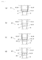
- FIGS. 4(a) to FIG. 4(d) are schematic views showing first to fourth modification examples near the tip end of the trunk portion 50 in the dilator 40.
- the trunk portions 50 viewed through the transparent sheaths 60 are shown in solid lines.
- the tapered portion 62 is kept from interfering with a peripheral wall of the puncture hole H (refer to FIG. 7 ) during dilation.
- a step in a diameter-decreasing direction that is, a step that decreases in diameter toward the tip end side, is present between the straight tube portion 53 of the trunk portion 50 of a first modification example of FIG. 4(a) , and the base end portion 34 of the guide portion 30.
- the base end portion 34 has a smaller diameter than the straight tube portion 53.
- the tapered portion 62 of the sheath 60 is located at the base end portion 34. Since the thickness of the tapered portion 62 of the sheath 60 is present inside the step between the base end portion 34 and the straight tube portion 53, the tapered portion 62 of the sheath 60 is kept from interfering with the peripheral wall of the puncture hole H.
- a step in a diameter-increasing direction that is, a step that increases in diameter toward the tip end side, is present between the straight tube portion 53 of a second modification example of FIG. 4(b) , and the base end portion 34.
- the base end portion 34 has a larger diameter than the straight tube portion 53.
- the tapered portion 62 of the sheath 60 is in contact with a lower end of the straight tube portion 53, that is, a base end side of the base end portion 34.
- the thickness of at least a portion of the tapered portions 62 of the sheath 60 is accommodated in the step between the base end portion 34 and the straight tube portion 53. For this reason, the tapered portion 62 of the sheath 60 is kept from interfering with the peripheral wall of the puncture hole H.
- the base end portion 34 of a third modification example of FIG. 4(c) has a small-diameter constricted portion 34a formed at an intermediate portion in the axial direction (a vertical direction of this drawing).
- the external diameter decreases smoothly from a lower end of the straight tube portion 53 to the constricted portion 34a.
- the tapered portion 62 of the sheath 60 is located at the constricted portion 34a. For this reason, the peripheral wall of the puncture hole H dilated by the diameter-enlarging portion 42 and the tapered portion 62 are kept from interfering with each other.
- an inclined surface 34b is formed continuously with a tip end side of the constricted portion 34a.
- the inclined surface 34b has an inverted tapered shape that is dilated toward the tip end side. By forming this inclined surface 34b on the base end portion 34, the guide portion 30 does not interfere with the tapered portion 62 when the sheath 60 is indwelled in the puncture hole (fistula) H and the dilator 40 is extracted from the sheath 60 (refer to FIG. 8(d) ).
- an inclined surface 34b is provided at the step in the diameter-increasing direction between the straight tube portion 53 and the base end portion 34 in the second modification example (refer to FIG. 4 (b) ).
- the inclined surface 34b has an inverted tapered shape that is dilated toward the tip end side.
- the tapered portion 62 of the sheath 60 is located on the inclined surface 34b. Since the tapered portion 62 of the sheath 60 is concealed behind the inclined surface 34b, the tapered portion 62 of the sheath 60 is kept from interfering with the peripheral wall of the puncture hole H.
- the guide portion 30 does not interfere with the tapered portion 62 when the sheath 60 is indwelled in the puncture hole (fistula) H and the dilator 40 is extracted from the sheath 60.
- a fine-diameter region that is smaller than the maximum external diameter of the diameter-enlarging portion 42 may be formed at the connecting boundary B between the guide portion 30 and the trunk portion 50 or its tip end side, and the sheath 60 may be mounted on the trunk portion 50 so that the tapered portion 62 is located in the fine-diameter region.
- the sheath 60 includes a gripper 66, a valve portion 65, and a tubular portion 63.
- the tubular portion 63 is made of a transparent resin material.
- the tubular portion 63 is formed with a half-cut groove 64.
- the half-cut groove 64 is formed over the total length of the tubular portion 63 in the lengthy direction.
- the valve portion 65 is in contact with an inner peripheral surface of the tubular portion 63 on the base end side.
- a base end side of the valve portion 65 is fixed to the gripper 66, and a tip end side thereof is rockable with respect to the gripper 66. Accordingly, an opening of the tubular portion 63 on the base end side is openable and closable and is airtightly closed.
- the medical dilating instrument 100 of the present embodiment is used together with the gastrostomy catheter 70 and an obturator 80 (refer to FIGS. 6(a) and 6(b) ).
- the gastrostomy catheter 70 is also referred to a gastric-fistula button.
- the gastrostomy catheter 70 is a catheter that is indwelled from a body surface to the inside of the stomach wall, and is an instrument that enables enteral nutrition intake to be performed by the percutaneous endoscopic gastrostomy (PEG).
- a tip end of the gastrostomy catheter 70 is formed with a flexible intracorporeal indwelling portion 72.
- the obturator 80 of the present embodiment is an instrument that is inserted through the gastrostomy catheter 70 to extend the intracorporeal indwelling portion 72 to thereby reduce the diameter of a forefront portion of the intracorporeal indwelling portion 72 to a fine diameter smaller than the sheath 60.
- FIG. 6(a) shows a state where the obturator 80 is mounted on the inside of the gastrostomy catheter 70.
- FIG. 6(b) shows a state where the obturator 80 is pressed toward the tip end side (downward in this drawing) with respect to the gastrostomy catheter 70 and thereby the tip end of the obturator 80 extends the intracorporeal indwelling portion 72 downward.
- the intracorporeal indwelling portion 72 is of a non-balloon type (malecot type) as an example.
- the gastrostomy catheter 70 has a straight tube portion 73 that is inserted into the fistula, an abutting plate 75 formed in the upper portion of the straight tube portion 73, and a blocking plug 74 that blocks an opening of the straight tube portion 73 on the base end side.
- a method for forming the fistula in the body wall by the medical dilating instrument 100 of the present embodiment to indwell the gastrostomy catheter 70 will be described with reference to FIGS. 7 , 8 , and 9 .
- an abdominal wall 300 and a stomach wall 310 are fixed with a suture 320 so as to surround the periphery of a predetermined forming position of a puncture hole.
- the cannular needle 20 is configured by connecting the guide portion 30 and the needle body 10.
- the needle tip 11 of the needle body 10 is in the puncture state where the needle tip has protruded from the tip end 31 of the guide portion 30.
- the needle body 10 is perpendicularly bumped against the abdominal wall 300, and the abdominal wall 300 is punctured by the needle tip 11.
- the cannular needle 20 of the present embodiment has a total length that is approximately equal to the needle body 10 shorter than the trunk portion 50 excluding the trunk portion 50. For this reason, the needle tip 11 can puncture precise intended predetermined forming position of the puncture hole.
- the cannular needle 20 is further pushed in, and the tip end 31 of the guide portion 30 is inserted inside the puncture hole H, following the needle tip 11. Accordingly, the puncture hole H is dilated to the external diameter of the capillary portion 32 of the guide portion 30.
- the tip end 31 of the guide portion 30 preferably protrudes from a lower surface (inner surface) of the stomach wall 310.
- the capillary portion 32 of the guide portion 30 is preferably longer than the total thickness of the abdominal wall 300 and the stomach wall 310.
- the needle body 10 (not shown in this drawing) is extracted from the guide portion 30 with the guide portion 30 being indwelled in the puncture hole H, and the cannular needle 20 (the same) is shifted to the protection state. Accordingly, the mounting portion 35 of the guide portion 30 opens. The mounting portion 35 is formed at the base end portion 34 of the guide portion 30 exposed above the puncture hole H.
- the lid body 36a is installed in the inner cavity 36 of the guide portion 30.
- the lid body 36a of the present embodiment is a duck bill valve that unidirectionally regulates an air current that flows from the tip end 31 of the guide portion 30 to the base end portion 34.
- the needle portion 12 of the needle body 10 is inserted through the lid body 36a.
- the needle portion 12 is extracted from the lid body 36a. Accordingly, the lid body 36a closes the inner cavity 36.
- the inside of the body cavity (stomach) is filled with gas with higher pressure than the atmospheric pressure.
- the lid body 36a prevents the filler gas from leaking out through the guide portion 30 in the third step and its subsequent steps. As the lid body 36a closes the inner cavity 36 in a dilating step to be described below, the filler gas is kept from leaking out from the body cavity in the dilating step.
- the tip end portion 52 of the trunk portion 50 mounted with the sheath 60 is mounted on the mounting portion 35 of the guide portion 30.
- the sheath 60 is slidable with respect to the trunk portion 50.
- this tip end portion 52 is mounted on the mounting portion 35.
- the guide wire 90 may be arbitrarily used.
- the trunk portion 50 is mounted on the mounting portion 35 along the guide wire 90.
- the guide wire 90 is inserted through the lid body 36a, and protrudes further than the tip end 31 of the guide portion 30.
- the guide wire 90 is sufficiently thin, and the filler gas within the stomach does not leak out significantly from a gap between the lid body 36a and the guide wire 90.
- FIG. 8 (b) shows a state where the trunk portion 50 and the guide portion 30 are combined together to configure the dilator 40.
- the sheath 60 is closely mounted around the trunk portion 50.
- the tip end 31 of the dilator 40 (guide portion 30) protrudes from the lower surface (inner surface) of the stomach wall 310, the puncture hole H with the external diameter of the capillary portion 32 is formed to penetrate from the abdominal wall 300 to the stomach wall 310.
- the puncture hole H reaching the inside of the body cavity (stomach) is formed in advance, the dilator 40 can be smoothly inserted inside the body wall (the abdominal wall 300 and the stomach wall 310) in fifth to sixth steps to be described below.
- FIGS. 8(c) and 8(d) show the dilating steps.
- the capillary portion 32 of the guide portion 30 is indwelled in the puncture hole H when the dilation is started. For this reason, the dilation is started in a state where the self-restoration of the abdominal wall 300 and the stomach wall 310 is suppressed.
- the trunk portion 50 is gripped and the dilator 40 is thrust into the puncture hole H.
- the diameter-enlarging portion 42 enters the abdominal wall 300 and the stomach wall 310 to dilate the puncture hole H.
- the trunk portion 50 is thrust into the puncture hole H, following the diameter-enlarging portion 42.
- the diameter-enlarging portion 42 reaches the inside of the body cavity (stomach) below the stomach wall 310.
- the tapered portion 62 of the sheath 60 reaches a portion below the stomach wall 310 together with the diameter-enlarging portion 42.
- the diameter of the puncture hole H is equal to the maximum external diameter of the diameter-enlarging portion 42, that is, the external diameter of the straight tube portion 53 of the trunk portion 50. It is preferable to indwell the endoscope (not shown) within the body cavity (within the stomach) and optically observe the vicinity of the puncture hole H.
- the reference scale 37 is matched with the anterior wall of the stomach, for example, by retreating the dilator 40 slightly.
- the total thickness of the abdominal wall 300 and the stomach wall 310 is measured from the read value of the scale portion 58 viewed at the body surface (the upper surface of the abdominal wall 300) in that state.
- the effective length size of the gastrostomy catheter 70 is determined based on this read value.
- the sheath 60 is indwelled in the puncture hole H, and the dilator 40 and the guide wire 90 are extracted.
- the puncture hole (fistula) H is formed from the above.
- the guide wire 90 may be extracted prior to the dilator 40.
- the gastrostomy catheter 70 is inserted into the sheath 60 indwelled in the dilated puncture hole H.
- the opening of the tubular portion 63 on the base end side is closed by the valve portion 65.
- the obturator 80 is inserted into the gastrostomy catheter 70, and the intracorporeal indwelling portion 72 is extended to the tip end side and decreased in diameter. If the intracorporeal indwelling portion 72 is inserted into the sheath 60, the half-cut groove 64 of the tubular portion 63 breaks from the base end side, and the sheath 60 is torn off.
- the gastrostomy catheter 70 is inserted inside the puncture hole H, tearing off the sheath 60.
- the gastrostomy catheter 70 is inserted inside the puncture hole (fistula) H until the intracorporeal indwelling portion 72 is confirmed within the stomach (under the endoscope).
- the abutting plate 75 is larger than the puncture hole H after the dilation.
- the gastrostomy catheter 70 and the obturator 80 are inserted inside the puncture hole (fistula) H, and the torn-off sheath 60 (not shown in this drawing) is extracted from the puncture hole (fistula) H.
- a ninth step shown in FIG. 9(c) release of the extension of the obturator 80 (not shown in this drawing) is performed, and the obturator 80 is then extracted from the gastrostomy catheter 70.
- the intracorporeal indwelling portion 72 increases in diameter to its natural state.
- the intracorporeal indwelling portion 72 in the natural state has a larger diameter than the puncture hole H after the dilation.
- the gastrostomy catheter 70 is indwelled without separating from the puncture hole H. This completes the indwelling of the gastrostomy catheter. Except for a case where instruments, such as a tube, are inserted into the gastrostomy catheter 70, the opening 77 of the straight tube portion 73 on the base end side is blocked by the blocking plug 74.
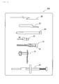
- FIG. 10 is a schematic view showing a medical dilating instrument set 200 used for the above-described gastric fistula forming method.
- the left side of this drawing corresponds the tip end sides of the respective instruments.
- the medical dilating instrument set 200 includes the needle body 10 having the pointed needle tip 11, the guide portion 30 having an elongated shape formed so that the tip end thereof is duller than the needle tip 11, and having the mounting portion 35 at the base end, the trunk portion 50 having a larger diameter than the guide portion 30, and the diameter-enlarging portion 42 that is provided at the guide portion 30 or the trunk portion 50 (at the guide portion 30 in the present embodiment) and increases in diameter from the tip end side toward the base end side.
- the needle body 10, the guide portion 30, and the trunk portion 50 are configured as separate bodies.
- the needle body 10 or the trunk portion 50 is alternatively mounted on the mounting portion 35, the guide portion 30 is arranged along the needle body 10 within the proximity by the needle body 10 is mounted on the mounting portion 35 and the needle tip 11 protrudes further than the tip end 31 of the guide portion 30, and the trunk portion 50 is mounted on the mounting portion 35 of the guide portion 30 from witch the needle body 10 (refer to FIG. 2 ) is separated.
- the medical dilating instrument set 200 of the present embodiment includes the sheath 60 that is used in a state being mounted around the trunk portion 50 and is capable of being torn off along the axis direction of the trunk portion 50, the gastrostomy catheter 70, and the obturator 80. That is, the medical dilating instrument set 200 of the present embodiment is a gastrostomy set for indwelling the gastrostomy catheter in the body wall.
- the needle body 10 is preferably housed in a protective case 19.
- the guide wire 90 may be arbitrarily included in the medical dilating instrument set 200.
- the aforementioned respective instruments that constitute the medical dilating instrument set 200 are included in a package or are individually provided.
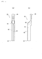
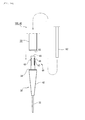
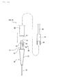
- FIG. 11 (a) is an exploded front view of the cannular needle 20 of a second embodiment of the invention. Specifically, FIG. 11(a) is a front view showing a state where the needle body 10 is inserted into the guide portion 30 in a direction shown by an arrow. FIG. 11 (b) is a front view of the cannular needle 20 obtained by connecting the guide portion 30 and the needle body 10. FIG. 11(a) shows the protection state of the cannular needle 20, and FIG. 11 (b) shows the puncture state of the cannular needle 20.
- the guide portion 30 of the present embodiment is different from that of the first embodiment in that there is a curved pipe portion 38.
- the curved pipe portion 38 is a tubular member having flexibility.
- the curved pipe portion 38 is made of soft resin materials, such as fluorine, urethane, and silicone rubber.
- the bending rigidity of the curved pipe portion 38 is sufficiently smaller than the bending rigidity of the needle portion 12.
- the curved pipe portion 38 and the other portions in the guide portion 30 may be made of the same materials, or the curved pipe portion 38 may be made of another materials with lower rigidity compared to the aforementioned other portions.
- the centerline of the curved pipe portion 38 is curved or crooked with respect to the centerline (the vertical direction of FIG. 11(a) ) of the guide portion 30.
- the capillary portion 32 of the present embodiment has a linear shape as the first embodiment on the base end side, and a partial length thereof on the tip end side is curved.
- the tip end 31 of the capillary portion 32 is directed laterally with respect to the centerline of the guide portion 30, specifically, is directed to a direction substantially orthogonal to the centerline, in the natural state (protection state) shown in FIG. 11 (a) .
- the position of the curved pipe portion 38 in the guide portion 30 is not particularly limited.
- the curved pipe portion 38 may be formed at a tip end portion including the tip end 31. Otherwise, a tip end portion including the tip end 31 may be formed in the shape of a straight pipe, and the curved pipe portion 38 may be formed at an intermediate portion of the guide portion 30.
- the curved pipe portion 38 and the capillary portion 32 communicate with the inner cavity 36 of the diameter-enlarging portion 42.
- the needle tip 11 of the needle portion 12 is inserted into the mounting portion 35 that is the opening of the guide portion 30 on the base end side.
- the needle tip 11 reaches the capillary portion 32 from the inner cavity 36.
- the needle tip 11 deforms the curved pipe portion 38 straightly (refer to FIG. 11(b) ).
- the length of the capillary portion 32 including the curved pipe portion 38 is equal to the capillary portion 32 of the first embodiment, and the needle tip 11 protrudes further than the tip end 31 of the capillary portion 32 in the puncture state where the head 15 is mounted on the mounting portion 35.
- the curved pipe portion 38 is flexibly curved when the tip end 31 has bumped against the body cavity wall (the rear wall of the stomach) in the protection state where the needle body 10 is extracted from the guide portion 30. Accordingly, even when the insertion depth of the dilator 40 is large, the tip end 31 does not strongly contact the body cavity wall.
- the curved angle of the curved pipe portion 38 that is, the angle formed between the centerline of a proximal portion of the curved pipe portion 38 and the centerline of a distal portion is 15 degrees or more and 180 degrees or less and preferably 45 degrees or more and 120 degrees or less.
- FIG. 12(a) is a longitudinal cross-sectional view showing the medical dilating instrument 100 of a third embodiment of the invention. This drawing shows the protection state of the cannular needle 20. Illustration of the sheath 60 (refer to FIG. 3 ) mounted around the trunk portion 50 will not be repeated.
- FIG. 12 (b) is a longitudinal cross-sectional view showing the puncture state of the cannular needle 20 of the present embodiment.
- a hollow accommodating portion 56 is formed inside the trunk portion 50 of the present embodiment.
- the needle body 10 is different from those of the first and the second embodiments in that the needle body 10 is accommodated in the accommodating portion 56 in the protection state.
- the tip end portion 52 of the trunk portion 50 is mounted on the base end portion 34 in a state where the head 15 of the needle body 10 is fitted to the base end portion 34 of the guide portion 30.
- a sliding portion 17 is formed at the base end portion 14 of the needle body 10 so as to protrude laterally (to the right side of respective drawings of FIG. 12 ).
- the sliding portion 17 has an elongated shape that extends in the direction of the tip and base ends (the vertical direction of the respective drawings).
- a slit 53a is formed in the axial direction in the straight tube portion 53 of the trunk portion 50.
- the sliding portion 17 slides in the axial direction inside the slit 53a.
- a base end portion of the straight tube portion 53 is formed with an enlarged-diameter head 53b in which the internal diameter of the accommodating portion 56 increases in diameter.
- the slit 53a extends from an intermediate portion of the enlarged-diameter head 53b to a tip end 51.
- the needle body 10 has a smaller diameter than the internal diameter of the straight tube portion 53 of the trunk portion 50 except for the collar portion 16.
- the external diameter of the collar portion 16 is smaller than the internal diameter of the enlarged-diameter head 53b, and is larger than the internal diameter of the straight tube portion 53.
- the collar portion 16 is made of flexible materials, such as resin, is pressed against and deflected by an inner wall surface of the straight tube portion 53 inside the straight tube portion 53, and, is elastically restored to the natural state inside the enlarged-diameter head 53b. Operators, such as a doctor, can operate the sliding portion 17 to make the needle body 10 slide inside the guide portion 30 and the trunk portion 50.
- the cannular needle 20 of the present embodiment freely shifts to the protection state and the puncture state.
- the collar portion 16 of the needle body 10 is sealed by a step surface 53c of a lower end of the enlarged-diameter head 53b.
- the needle tip 11 of the needle body 10 is located further toward the base end side than the tip end 51 of the trunk portion 50. That is, the needle portion 12 of the needle body 10 is accommodated in the trunk portion 50 over its total length.
- the collar portion 16 of the needle body 10 abuts against the mounting portion 35 of the guide portion 30 whereby the needle body 10 and the guide portion 30 are connected together.
- the needle tip 11 of the needle body 10 protrudes from the tip end 31 of the guide portion 30. Accordingly, the cannular needle 20 is configured.
- the trunk portion 50 is further mounted on the mounting portion 35 in a state where the needle body 10 is mounted on the mounting portion 35 of the guide portion 30.
- the mounting portion 35 of the guide portion 30 of the present embodiment has a step-like shape, and the tip end 51 of the trunk portion 50 is ruggedly fitted around the collar portion 16 mounted on the mounting portion 35 (refer to FIG. 12 (a) ). Accordingly, in the fourth step of the gastric fistula formation shown in FIG. 8(a) , it is possible to connect the tip end portion 52 of the trunk portion 50 with the mounting portion 35 of the guide portion 30 in a state where the needle body 10 is connected to the guide portion 30.
- the medical dilating instrument 100 can be shifted to the protection state. Accordingly, it is possible to safely discard the dilator 40 without touching of the needle tip 11 of the needle body 10 by an operator after the termination of the procedures of the gastric fistula forming method.
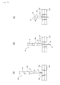
- FIG. 13(a) is a longitudinal cross-sectional view showing the cannular needle 20 of a fourth embodiment of the invention.
- FIG. 13 (b) is an enlarged cross-sectional view of the vicinity of the needle tip 11.
- FIG. 13(c) is a longitudinal cross-sectional view showing the needle body 10 on which a needle tip protecting member 39 is mounted.
- the needle tip protecting member 39 is mounted inside or around the guide portion 30 of the present embodiment (refer to FIG. 13 (a) ). Also, there is a feature that the needle tip protecting member 39 is mounted on the needle body 10 to cover the needle tip 11 by extracting the needle body 10 in the puncture state from the guide portion 30 (refer to FIG. 13(c) ).
- the needle tip protecting member 39 covers the needle tip 11 of the needle body 10. Accordingly, the needle body 10 can be safely discarded.
- the specific shape of the needle tip protecting member 39 is not particularly limited, the needle tip protecting member 39 of the present embodiment has a tube shape.
- the needle tip protecting member 39 opens on a tip end side, and has a top bottom 39a provided on a base end side.
- the needle body 10 includes a protrusion 18 that is engaged with the needle tip protecting member 39 when being extracted from the guide portion 30.
- the columnar protrusion 18 is anchored to an intermediate portion of the needle portion 12.
- the protrusion 18 is accommodated inside the capillary portion 32 in the puncture state.
- the protrusion 18 of the needle portion 12 reaches the diameter-enlarging portion 42 from the capillary portion 32. If the needle body 10 is further extracted, the protrusion 18 enters the inside of the needle tip protecting member 39 accommodated in the inner cavity 36 of the diameter-enlarging portion 42, and reaches the top bottom 39a of the needle tip protecting member 39.
- the top bottom 39a is formed with a sliding hole with a larger diameter than the external diameter of the needle portion 12 and a smaller diameter than the external diameter of the protrusion 18.
- FIG. 13 (c) shows this protection state.
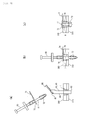
- FIG. 14 is an exploded view of the medical dilating instrument 100 of a fifth embodiment of the invention.
- the trunk portion 50 As for the trunk portion 50, only a portion on a tip end side is shown and illustration of a base end side will not be repeated.
- the tip end portion 52 of the trunk portion 50 is connected to the base end portion 34 of the guide portion 30, and a direction in which an engagement assisting member 82 is inserted into the trunk portion 50 is shown by an arrow.
- FIG. 15 is a cross-sectional schematic view of the medical dilating instrument 100 of the present embodiment.
- the dilator 40 is configured by connecting the cannular needle (that is, the guide portion 30), which is in the protection state by the needle body 10 (not shown) being extracted, and the trunk portion 50.
- the tip end portion 52 of the trunk portion 50 or the head 15 of the needle body 10 (refer to FIG. 1 ) is alternatively fitted to the base end portion 34 of the guide portion 30.
- the medical dilating instrument 100 of the present embodiment includes a locking mechanism 88 that releasably connects the guide portion 30 and the trunk portion 50.
- the locking mechanism 88 is a unit that prohibits the separation between the guide portion 30 and the trunk portion 50 that are in a mutually connected state.
- the locking mechanism 88 of the present embodiment includes a locking piece 46 and an engaging portion 59.
- the locking piece 46 is provided on one of the guide portion 30 or the trunk portion 50.
- the engaging portion 59 is provided on the other of the guide portion 30 or the trunk portion 50, and is engageable with the locking piece 46.
- the locking mechanism 88 releasably connects the guide portion 30 and the trunk portion 50
- shifting is made to a first state where the guide portion 30 and the trunk portion 50 are directly or indirectly connected together and a second state where both are separable by the operation of the locking mechanism 88.
- FIG. 15 illustrates that the guide portion 30 including the diameter-enlarging portion 42 is to be separated from the trunk portion 50, the invention is not limited to this.
- the diameter-enlarging portion 42 and the capillary portion 32 (guide portion 30) may be separated by the operation of the locking mechanism 88.
- a tubular connecting portion 43 is inserted into and fixed to an opening of the base end portion 34 of the diameter-enlarging portion 42.
- the diameter-enlarging portion 42 and the connecting portion 43 may be bonded together.
- a base end (an upper end of FIG. 15 ) of the connecting portion 43 is formed with an annular portion 45.
- the locking piece 46 is formed on the tip end side adjacent to the annular portion 45 of the connecting portion 43.
- the locking piece 46 has a triangular claw shape that protrudes outward in the radial direction of the connecting portion 43. As shown in FIG. 15 , the locking piece 46 is constituted by a lower taper 47 on the tip end (lower end) side, and an upper taper 48 on the base end (upper end) side. In addition, it is arbitrary to form the locking piece 46 with the upper taper 48.
- a plurality of the locking pieces 46 are arranged around the connecting portion 43 so as to face each other or are arranged so as to be radially distributed.
- An individual locking piece 46 is able to be projected and retracted inward and outward in the radial direction of the connecting portion 43.
- the projection height of the locking piece 46 is increased by pressing the locking piece 46 outward from the inside of the tubular connecting portion 43.
- a flange tube portion 54 is crowned on the tip end portion 52 of the trunk portion 50.
- a tubular upper end (engaging portion 59) of the flange tube portion 54 has a taper shape that inclines inward and downward.
- the flange tube portion 54 may be formed integrally with the trunk portion 50 from one material.
- the medical dilating instrument 100 (dilator 40) of the present embodiment includes the engagement assisting member 82 (illustration of a portion thereof will not be repeated) used in a state being inserted into the trunk portion 50.
- the engagement assisting member 82 illustratedration of a portion thereof will not be repeated
- the projection height of the locking piece 46 increases. Accordingly, as compared to a case where the engagement assisting member 82 is not used, the locking piece 46 is more deeply engaged with the engaging portion 59 by inserting the engagement assisting member 82 into the trunk portion 50. Accordingly, the lower taper 47 of the locking piece 46 and the engaging portion 59 are engaged with each other, and entry of the connecting portion 43 into the flange tube portion 54 is regulated.
- Both of the lower taper 47 and the engaging portion 59 have a taper shape that inclines inward and downward in the radial direction of the medical dilating instrument 100.
- the lower taper 47 and the engaging portion 59 incline in the same direction, and when the locking piece 46 is biased to the tip end side with respect to the engaging portion 59, the locking piece 46 is retracted inward in the radial direction of the medical dilating instrument 100 along this inclination direction.
- the external diameter of the locking piece 46 is deformed to be equal to or less than the internal diameter of the flange tube portion 54, and the locking piece 46 and the engaging portion 59 are separable from each other by some or all of the engagement therebetween being released. That is, the overall connecting portion 43 including the locking piece 46 is extractable from the flange tube portion 54 by extracting the engagement assisting member 82 from the trunk portion 50.
- the engagement assisting member 82 has a rod shape.
- the external diameter of the engagement assisting member 82 is smaller than the internal diameter of the insertion hole 55 (refer to FIG. 2 ) of the trunk portion 50 and the internal diameter of the annular portion 45, and the engagement assisting member 82 is insertable into the insertion hole 55 and the annular portion 45.
- the dilator 40 of the present embodiment is not locked in a state where the engagement assisting member 82 is not inserted, and the guide portion 30 and the trunk portion 50 are engageable and releasable.
- FIG. 16 is an exploded view of the medical dilating instrument 100 of a sixth embodiment of the invention.
- the trunk portion 50 As for the trunk portion 50, only a portion on a tip end side is shown and illustration of a base end side will not be repeated.
- the tip end portion 52 of the trunk portion 50 is connected to the base end portion 34 of the guide portion 30, and a direction in which a releasing member 84 is inserted into the trunk portion 50 is shown by an arrow.
- FIG. 17 is a cross-sectional schematic view of the medical dilating instrument 100 of the present embodiment.
- the dilator 40 is configured by connecting the cannular needle (that is, the guide portion 30), which is in the protection state by the needle body 10 (not shown) being extracted, and the trunk portion 50.
- the medical dilating instrument 100 of the present embodiment is common to that of the fifth embodiment in that this medical dilating instrument includes the locking mechanism 88 that releasably connects the guide portion 30 and the trunk portion 50. Also, the present embodiment is different from the fifth embodiment in that the guide portion 30 and the trunk portion 50 are locked in a non-insertion state of the releasing member 84 and are unlocked by inserting the releasing member 84 into the trunk portion 50.
- the medical dilating instrument 100 of the present embodiment includes the releasing member 84 used in a state being inserted into the trunk portion 50. Also, the locking piece 46 and the engaging portion 59 are separable from each other by inserting the releasing member 84 into the trunk portion 50 to release some or all of the engagement between the locking piece 46 and the engaging portion 59.
- the locking piece 46 of the present embodiment is constituted by a stepped portion 49 on the tip end (lower end) side, and the upper taper 48 on the base end (upper end) side.
- the stepped portion 49 which is an end surface on a lower end side of the locking piece 46, is erected in the radial direction of the connecting portion 43.
- the upper end (engaging portion 59) of the flange tube portion 54 of the present embodiment is different from that of the fifth embodiment in that it is not in a taper shape that inclines inward and downward but rather, it is erected at a substantially right angle with respect to the axial direction of the flange tube portion 54.
- the external diameter of the locking piece 46 is larger than the internal diameter of the engaging portion 59.
- the locking piece 46 is able to be projected and retracted inward and outward in the radial direction of the tubular connecting portion 43.
- the projection height of the locking piece 46 is decreased by pressing the connecting portion 43 inward in the radial direction.
- the releasing member 84 includes a rod-shaped shaft portion 85, and an annular pressing portion 86 formed at a tip end (a lower end) of the shaft portion 85.
- the pressing portion 86 has a larger diameter than the shaft portion 85.
- the external diameter of the pressing portion 86 is smaller than the internal diameter of the insertion hole 55 (refer to FIG. 2 ) of the trunk portion 50, and the releasing member 84 is insertable into the trunk portion 50.
- the internal diameter of the pressing portion 86 is smaller than the external diameter of the locking piece 46. As shown in FIG.
- the diameter of the connecting portion 43 becomes a diameter such that the connection portion 43 is inserted into the flange tube portion 54 as the pressing portion 86 causes the locking piece 46 to be retracted inward in the radial direction. Accordingly, the locking mechanism 88 is unlocked and the guide portion 30 and the trunk portion 50 are separable from each other.
- the diameter-enlarging portion 42 does not become unstable during dilating procedures.
- An operator is able to extract the engagement assisting member 82 from the trunk portion 50 of the dilator 40 or insert the releasing member 84 into the trunk portion 50 to unlock the locking mechanism 88, thereby simply separating the trunk portion 50 and the guide portion 30 from each other. Accordingly, for example, as shown in FIG. 8(b) , even after the dilator 40 is configured, it is possible to easily separate the trunk portion 50 to finely operate the guide portion 30 or the guide wire 90 for a procedure.
- the fifth and sixth embodiments illustrate that the locking mechanism 88 is operated for release, using the engagement assisting member 82 or the releasing member 84 that is a body separate from the guide portion 30 or the trunk portion 50.
- the invention is not limited to this.
- a configuration may be adopted in which the engagement between the locking piece 46 and the engaging portion 59 is releasable by a finger operation.
- slits through which the locking piece 46 in the state of being engaged with the engaging portion 59 is inserted may be formed in_a peripheral surface of the trunk portion 50.
- an elastic member that biases the trunk portion 50 and the guide portion 30 in mutually separating directions may be provided.
- an elastic member (spiral spring: not shown) may be provided inside the annular pressing portion 86.
- this spiral spring elastically biases an upper end of the annular portion 45 or the upper taper 48 downward, and extraction of the connecting portion 43 from the flange tube portion 54 is assisted in.
Landscapes
- Health & Medical Sciences (AREA)
- Life Sciences & Earth Sciences (AREA)
- General Health & Medical Sciences (AREA)
- Animal Behavior & Ethology (AREA)
- Surgery (AREA)
- Veterinary Medicine (AREA)
- Public Health (AREA)
- Gastroenterology & Hepatology (AREA)
- Engineering & Computer Science (AREA)
- Medical Informatics (AREA)
- Molecular Biology (AREA)
- Heart & Thoracic Surgery (AREA)
- Biomedical Technology (AREA)
- Nuclear Medicine, Radiotherapy & Molecular Imaging (AREA)
- Pathology (AREA)
- Media Introduction/Drainage Providing Device (AREA)
- Medical Preparation Storing Or Oral Administration Devices (AREA)
- Surgical Instruments (AREA)
Abstract
Description
- The invention relates to a medical dilating instrument and a medical dilating instrument set.
- There are known dilators that dilates a small needle hole (puncture hole) formed by puncturing the body walls of a human body with a puncture needle. The dilators have a diameter-enlarging portion that gradually increases in external diameter. By inserting a tip of a dilator inside a small puncture hole formed on a body wall and by subsequently thrusting the diameter-enlarging portion into the puncture hole, the puncture hole is gradually dilated. The dilator is extracted from the body wall at a time when the puncture hole is sufficiently dilated, and medical instruments, such as a catheter, are inserted. Accordingly, a medical instrument can be percutaneously inserted into and placed inside body cavities, such as a blood vessel, an abdominal cavity, or the stomach and the intestines.
-
Patent Document 1 describes a cannular needle (puncture needle with a dilator) obtained by inserting a puncture needle to a cannular in which a conical tube portion that increases in diameter is formed, and connecting both of the puncture needle and the cannular. An operator indwells the cannular and extracts the puncture needle from a body wall which is punctured by the puncture needle that has protruded from the cannular. After a guide wire is inserted into this cannular, a dilator, which is larger in diameter and longer than the cannular, is thrust into the body wall along the guide wire to dilate the puncture hole (refer toFIG. 7 of Patent Document 1). - Patent Document 2 describes an entry device in which a puncture needle is inserted through a tubular dilator. The dilator is longer and larger in diameter than the puncture needle. The puncture needle has a head formed at a base end portion. After a needle tip of the puncture needle is inserted from a base end side of the dilator, the head of the puncture needle is connected to a base end portion of the dilator. A sheath including a wing is mounted around the dilator. After the sheath is thrust into the puncture hole together with the dilator, the sheath is indwelled and the puncture needle and the dilator are extracted. Then, medical instruments, such as a catheter, are inserted into this sheath.
-
- [Patent Document 1] Japanese Unexamined Patent Application Publication No.
S63-246178 - [Patent Document 2] Published Japanese Translation No.
2010-524586 of the PCT - Since blood vessels are present in a mesh shape inside a patient' s body wall, it is necessary to carefully determine the indwell position of a medical instrument. For this reason, high precision is required for the puncture position of the puncture needle. Meanwhile, a simple procedure in dilating a puncture hole (hereinafter referred to as dilating procedure) is necessary to lessen doctor's work burden granted that the procedure is safe.
- Since the cannular needle of
Patent Document 1 has dimensions smaller than the dilator and has good handleability, a puncture hole can be formed on a precise intended body surface position. However, there are many and complicated number of steps in the dilating procedure using the cannular needle ofPatent Document 1, as there are steps to insert the guide wire into the cannular after the extraction of the puncture needle and to thrust the dilator along the guide wire. Additionally, since the body wall after the extraction of the cannular needle is self-restored and brought into close contact with the guide wire to bury the puncture hole, the procedure requires more skills, as it is necessary to insert the guide wire in a confirmed direction of the guide wire, when the dilator is inserted through the guide wire. - In the entry device of Patent Document 2, the puncture needle and the dilator are integrated together. Therefore, it is possible to puncture a body wall with the puncture needle and subsequently thrust the dilator into the puncture hole. For this reason, it is not necessary to indwell the guide wire in advance in the puncture hole before the dilator is thrust into the body wall, and the dilating procedure is simple. However, since the puncture needle and the dilator are integrated in the entry device of Patent Document 2, it is difficult for the puncture needle to puncture a precise intended body surface position. When an operator grips the vicinity of the puncture needle, the base end portion with a large moment of inertia hinders a puncture operation. Additionally, when the operator grips the base end portion, the distance from the operator hand to the tip of the puncture needle increases. Therefore, it is also difficult for the puncture needle to puncture a precise intended body surface position.
- The invention has been made in view of the above problems, and object thereof is to provide a medical dilating instrument and a medical dilating instrument set capable of forming a puncture hole with high positional precision and performing the following dilating operation of the puncture hole in a simple procedure.
- A medical dilating instrument of the invention includes a needle body having a pointed needle tip; an elongated guide portion formed so that a tip end thereof is duller than the needle tip; a trunk portion having a larger diameter than the guide portion; and a diameter-enlarging portion that is provided at the guide portion or the trunk portion and increases in diameter from a tip end side toward a base end side. The needle body and the guide portion are shifted from a puncture state where the needle body and the guide portion are connected to each other, the needle body is arranged along the guide portion within the proximity, and the needle tip protrudes further than the tip end of the guide portion, to a protection state where the needle tip is retreated from the tip end of the guide portion. The trunk portion is connected to a base end portion of the guide portion in the protection state.
- Additionally, a medical dilating instrument set of the invention includes a needle body having a pointed needle tip; a guide portion having an elongated shape formed so that a tip end thereof is duller than the needle tip and having a mounting portion at a base end; a trunk portion having a larger diameter than the guide portion; and a diameter-enlarging portion that is provided at the guide portion or the trunk portion and increases in diameter from a tip end side toward a base end side. The needle body, the guide portion, and the trunk portion are constituted as separate bodies. The needle body or the trunk portion is mounted on the mounting portion and thereby the guide portion is arranged along the needle body within the proximity by mounting the needle tip on the mounting portion and the needle tip protrudes further than the tip end of the guide portion. The trunk portion is mounted on the mounting portion from which the needle body is separated.
- In the above invention, the puncture state means a state where the needle tip protrudes further than the tip end of the guide portion and the needle tip is capable of puncturing a body wall. The protection state means a state where the needle tip is retreated from the tip end of the guide portion, and includes a state where the needle body is extracted from the guide portion, and a state where the needle body and the guide portion move relative to each other while being connected to each other and the needle body has moved further toward the base end side than the tip end of the guide portion.
- According to the above invention, the trunk portion can be connected to the base end portion of the guide portion after the needle body is shifted to the protection state after the needle tip of the needle body in the puncture state has punctured the body wall. For this reason, by connecting the trunk portion to the base end portion exposed from the body wall in a state where the tip end side of the elongated guide portion is inserted inside the body wall together with the needle tip, it is possible to configure the dilator with the sufficient diameter. Hence, the needle tip can puncture a precise intended body surface position irrespective of the magnitude of the moment of inertia of the trunk portion having a larger diameter. Moreover, the dilator (diameter-enlarging portion) can be safely thrust (dilated) into a puncture hole with the guide portion as a guide in a state after the needle body is shifted to the protection state. At this time, since the dilation is started from a state where the guide portion is indwelled in the puncture hole and the self-restoration of the body wall is suppressed, the diameter-enlarging portion can be easily thrust into the puncture hole with low invasion.
- In addition, the various constituent elements of the invention do not need to be individually and independently preset, and the invention allows that a plurality of constituent elements are formed as one member, one constituent element is formed by a plurality of members, a certain constituent element is a portion of another constituent element, a portion of a certain constituent element and a portion of another constituent element overlap each other, or the like.
- According to the medical dilating instrument and the medical dilating instrument set of the invention, it is possible to form a puncture hole with high positional precision and perform the subsequent dilating operation of the puncture hole in a simple procedure.
- The aforementioned objects and other objects, features, and advantages will be apparent by the preferred embodiments to be described below and the following drawings attached thereto.
-
-
FIG. 1 is an exploded front view of a medical dilating instrument related to a first embodiment of the invention. -
FIG. 2 (a) is a longitudinal cross-sectional view of a cannular needle, andFIG. 2(b) is a longitudinal cross-sectional view of a dilator. -
FIG. 3 is a front view of a sheath dilator. -
FIGS. 4(a) to 4(d) are schematic views showing first to fourth modification examples of the vicinity of a tip end portion of a trunk portion in the sheath dilator. -
FIG. 5(a) is a front view of a sheath andFIG. 5(b) is a right side view of the sheath. -
FIG. 6(a) is a front view showing a state where an obturator is combined with a gastrostomy catheter. -
FIG. 6 (b) is a front view showing a state where the gastrostomy catheter is extended. -
FIGS. 7 (a) to 7(c) are front view showing first to third steps of forming a gastric fistula in a body wall. -
FIG. 8 (a) is a front view showing a fourth step of forming the gastric fistula,FIG. 8(b) is a front view showing a state where the sheath dilator is configured, andFIGS. 8 (c) and 8 (d) are front views showing fifth to sixth steps of forming the gastric fistula. -
FIGS. 9 (a) to 9 (c) are front views showing seventh to ninth steps of forming the gastric fistula. -
FIG. 10 is an explanatory view showing a medical dilating instrument set of the present embodiment. -
FIG. 11(a) is an exploded front view of a cannular needle of a second embodiment. -
FIG. 11(b) is a front view of the cannular needle. -
FIG. 12(a) is a longitudinal cross-sectional view showing a medical dilating instrument of a third embodiment, andFIG. 12(b) is a longitudinal cross-sectional view showing a cannular needle. -
FIG. 13(a) is a longitudinal cross-sectional view showing a cannular needle of a fourth embodiment. -
FIG. 13 (b) is an enlarged cross-sectional view of the vicinity of a needle tip. -
FIG. 13(c) is a longitudinal cross-sectional view showing a needle body on which a needle tip protecting member is mounted. -
FIG. 14 is an exploded view of a medical dilating instrument of a fifth embodiment. -
FIG. 15 is a cross-sectional schematic view of the medical dilating instrument of the fifth embodiment. -
FIG. 16 is an exploded view of a medical dilating instrument of a sixth embodiment. -
FIG. 17 is a cross-sectional schematic view of the medical dilating instrument of the sixth embodiment. - Hereinafter, embodiments of the invention will be described with reference to the drawings. In addition, in all the drawings, the same constituent elements will be designated by the same reference numerals, and the redundant description thereof will not be repeated.
- A
medical dilating instrument 100, a medical dilating instrument set 200 of the present embodiment, and a method of forming a gastric fistula in a body wall using the medical dilating instrument set 200 will be described with reference toFIGS. 1 to 10 . First, the outline of themedical dilating instrument 100 will be described. Hereinafter, an extending direction of aneedle body 10 is referred to as a lengthy direction or axial direction of themedical dilating instrument 100, and a cross-section along the lengthy direction is referred to as a longitudinal section of themedical dilating instrument 100. - The
medical dilating instrument 100 of the present embodiment includes theneedle body 10 having a pointedneedle tip 11, anelongated guide portion 30 formed so that atip end 31 thereof is duller than theneedle tip 11, and atrunk portion 50 having a larger diameter than theguide portion 30. As shown by a chain-line arrow inFIG. 1 , acannular needle 20 is configured by connecting theneedle body 10 and theguide portion 30, and adilator 40 is configured by connecting theguide portion 30 and thetrunk portion 50. Thedilator 40 includes a diameter-enlargingportion 42 that increases in diameter from a tip end side toward a base end side. The diameter-enlargingportion 42 is provided on one or both of theguide portion 30 and the trunk portion 50 (theguide portion 30 in the present embodiment). - The
cannular needle 20 shown inFIG. 2 (a) is in a puncture state where theneedle body 10 and theguide portion 30 are connected to each other, theneedle body 10 is arranged along theguide portion 30 within the proximity, and theneedle tip 11 protrudes further than thetip end 31 of theguide portion 30. On the other hand, thecannular needle 20 shown inFIG. 1 is in a protection state where theneedle body 10 is extracted from theguide portion 30 to the base end side, and theneedle tip 11 is retreated from thetip end 31 of theguide portion 30. Thecannular needle 20 is able to shift from the puncture state to the protection state. Thecannular needle 20 may shift irreversibly from the puncture state toward the protection state, or may shift reversibly to the puncture state and the protection state. Thecannular needle 20 of the present embodiment shifts reversibly to the puncture state and the protection state by inserting and extracting theneedle body 10 with respect to theguide portion 30. - The
guide portion 30 constitutes thecannular needle 20 to enter a body wall with low invasion together with aneedle portion 12 at the time of the puncture of theneedle body 10, while constituting thedilator 40 to function as a guide when thrusting the diameter-enlargingportion 42 and thetrunk portion 50 into the body wall. Theguide portion 30 of the present embodiment is constituted by acapillary portion 32 and the diameter-enlargingportion 42. Also, thecannular needle 20 is configured by combining theguide portion 30 and theneedle body 10. Meanwhile, thedilator 40 is configured by combining theguide portion 30 and thetrunk portion 50. - The
capillary portion 32 of theguide portion 30 is a portion that is arranged along theneedle portion 12 within the proximity that is connected to theneedle body 10 to configure thecannular needle 20. Although thecannular needle 20 in which thetubular capillary portion 32 is circumferentially attached to theneedle body 10 is illustrated in the present embodiment, the invention is not limited to this. A rod-shaped member arranged along theneedle portion 12 of theneedle body 10 may be used instead of thecapillary portion 32. Since themedical dilating instrument 100 of the present embodiment is an instrument that can form a fistula without using a guide wire 90 (refer toFIG. 8 ), themedical dilating instrument 100 does not necessarily have hollow structure. Accordingly, instead of thecapillary portion 32 of theguide portion 30, a rod-shaped member that is duller than theneedle tip 11 and having no hole may be arranged so as to be attached to theneedle portion 12. - As shown in
FIG. 2 (b) , thedilator 40 is configured by thetrunk portion 50 being connected to abase end portion 34 of theguide portion 30 that is in the protection state by theneedle body 10 being extracted from thecannular needle 20. Thetrunk portion 50 being connected at theguide portion 30 includes a state where both of the trunk portion and guide portion are directly joined together and a state where theguide portion 30 and thetrunk portion 50 are indirectly joined together with theneedle body 10 or other members being interposed therebetween. - Next, the
medical dilating instrument 100 will be described in detail. Themedical dilating instrument 100 is a medical device for puncturing a body wall to provide a puncture hole, further dilating this puncture hole, and percutaneously inserting and placing medical instruments, such as a catheter (a cannular), a needle, or various treatment tools, within a body cavity. Themedical dilating instrument 100 of the present embodiment is preferably used during the gastrostomy that forms a fistula through the abdominal wall and the stomach wall to indwell the gastrostomy catheter 70 (refer toFIG. 10 ). - The
needle body 10 is constituted by theneedle portion 12 and ahead 15. Abase end portion 14 of theneedle body 10 is formed with thehead 15. Thebase end portion 14 of theneedle body 10 indicates a predetermined length region on a side opposite to theneedle tip 11. The external diameter of theneedle portion 12 is preferably 0.5 mm or more and 4 mm or less. The external diameter of thehead 15 is larger than the external diameter of theneedle tip 11. Theneedle portion 12 has an inner cavity that has hollow structure and penetrates in an axial direction. An outer periphery of thehead 15 is formed with acollar portion 16 that protrudes outward in the radial direction. Thehead 15 has an inner cavity that penetrates in the axial direction. The inner cavities of thehead 15 and theneedle portion 12 communicate with each other, and are arbitrary, and enable theguide wire 90 to be inserted therethrough. A base end of theneedle portion 12 is anchored inside thehead 15. - As shown in
FIGS. 1 and2 , atip end portion 52 of thetrunk portion 50 or thehead 15 of theneedle body 10 is fitted to thebase end portion 34 of theguide portion 30. Thetip end portion 52 of thetrunk portion 50 or thehead 15 of theneedle body 10 is alternatively fitted to thebase end portion 34 of theguide portion 30 of the present embodiment. Specifically, thetip end portion 52 of thetrunk portion 50 or thehead 15 of theneedle body 10 is fitted to a mountingportion 35 corresponding to an opening portion on the base end side of thebase end portion 34. Theguide portion 30 of the present embodiment includes thecapillary portion 32 and the diameter-enlargingportion 42. The guide portion 30 (thecapillary portion 32 and the diameter-enlarging portion 42) has a tube shape including aninner cavity 36 with a larger diameter than the needle body 10 (needle portion 12). Theinner cavity 36 of the present embodiment is a hollow portion extending over the inside of thecapillary portion 32 to the inside of the diameter-enlargingportion 42. The internal diameter of thecapillary portion 32 is slightly larger than the external diameter of theneedle portion 12, and theneedle portion 12 is slidable inside thecapillary portion 32. The phrase "theguide portion 30 has an elongated shape" means that a fine-diameter portion (thecapillary portion 32 in the present embodiment), which can enter the puncture hole formed by theneedle tip 11 together with theneedle portion 12, is formed on the tip end side of theguide portion 30. Additionally, the phrase "thetrunk portion 50 has a larger diameter than theguide portion 30" means that astraight tube portion 53 of thetrunk portion 50 has a large diameter than thecapillary portion 32 of theguide portion 30. In addition, as in amedical dilating instrument 100 of a third embodiment to be described below, thetip end portion 52 of thetrunk portion 50 may be further mounted on thebase end portion 34 in a state where thehead 15 of theneedle body 10 is fitted to thebase end portion 34 of theguide portion 30. - As shown in
FIG. 2(a) , thetip end 31 of thecapillary portion 32 decreases in diameter in the shape of a taper. The internal diameter of thetip end 31 is equal to the external diameter of theneedle portion 12, and a peripheral surface of theneedle body 10 and a peripheral surface of thetip end 31 of thecapillary portion 32 are smoothly continuous. Additionally, thebase end 33 of thecapillary portion 32 increases in diameter in the shape of a taper, and is locked to and is retained by atip end 41 of the diameter-enlargingportion 42. The diameter-enlargingportion 42 continuously increases in diameter from thetip end 41 toward thebase end portion 34. Thebase end portion 34 has a straight tube shape that is the same as atermination end 44 of the diameter-enlargingportion 42 on a larger diameter side. - The
inner cavity 36 is provided with alid body 36a. Thelid body 36a is a member that permits insertion of theneedle body 10 and regulates an air current that flows from thetip end 31 of theguide portion 30 to thebase end portion 34 in the protection state. Accordingly, thelid body 36a prevents filler gas within a body cavity (stomach) from leaking out to the outside of the body through theguide portion 30 during formation of a gastric fistula. Here, the phrase "regulates an air current" means a state where the leakage of the filler gas within the body cavity has such a small flow rate that does not matter practically in addition to a state where an air current is substantially completely shielded. - The
lid body 36a may be integrally formed using the same materials as that of the guide portion 30 (thecapillary portion 32, thebase end portion 34, or the diameter-enlarging portion 42), or may be a separate member that is used in a state being mounted on theguide portion 30. The installation position of thelid body 36a in theinner cavity 36 is not particularly limited, and may be installed inside thecapillary portion 32, or may be installed inside the diameter-enlargingportion 42 or thebase end portion 34. Thelid body 36a of the present embodiment is a duck bill valve that has abase end portion 34 side of theguide portion 30 as an inflow side and has atip end 31 side as an outflow side. - In addition, a turning lid that turns around an axis extending in the radial direction of the
guide portion 30 to open and close theinner cavity 36, and a flap valve that reciprocally rocks similarly around an axis extending the radial direction of theguide portion 30 to open and close theinner cavity 36, may be used as thelid body 36a. Additionally, a blocking plug, which is made of soft elastic materials, such as rubber, and has an insertion hole with a larger diameter than theneedle portion 12 and the guide wire inserted therethrough, may be used as thelid body 36a. Thelid body 36a may be a member that, in addition to regulating an air current that flows from thetip end 31 of theguide portion 30 to thebase end portion 34, regulates an air current that flows backward from thebase end portion 34 to thetip end 31, as long as theneedle portion 12 can be inserted through thelid body 36a in the puncture state. - In the puncture state shown in
FIG. 2(a) , theneedle portion 12 of theneedle body 10 is inserted through thelid body 36a from thebase end portion 34 side toward thetip end 31 side. Thelid body 36a is brought into an open state in a state where theneedle portion 12 is inserted. In the protection state shown inFIG. 2(b) , theneedle portion 12 is extracted from thelid body 36a, and thelid body 36a is automatically brought into a closed state. The leaking of gas from the body cavity when theneedle portion 12 is extracted can be prevented by providing such alid body 36a in theguide portion 30. - As shown in
FIG. 2 (b) , thetip end portion 52 of thetrunk portion 50 has a small diameter than thestraight tube portion 53. An outer peripheral surface of thestraight tube portion 53 and an outer peripheral surface of thebase end portion 34 are continuous by thetip end portion 52 of thetrunk portion 50 being fitted to thebase end portion 34 of theguide portion 30. There is substantially no step between thebase end portion 34 and thestraight tube portion 53 at a connecting boundary B between thetrunk portion 50 and theguide portion 30. Accordingly, external diameter increases monotonically and continuously over thecapillary portion 32, the diameter-enlargingportion 42, thebase end portion 34, and thestraight tube portion 53 from thetip end 31 of theguide portion 30. For this reason, the puncture hole can be dilated with low invasion. - The
trunk portion 50 is longer than theguide portion 30. Thetrunk portion 50 is formed with aninsertion hole 55 for theguide wire 90. Theinsertion hole 55 passes through thetrunk portion 50 in the direction of the tip and base ends. In thedilator 40, theinsertion hole 55 communicates with theinner cavity 36 of the diameter-enlargingportion 42. A base end of thetrunk portion 50 is provided with aninsertion opening 57 for theguide wire 90. Thetrunk portion 50 is longer than thecannular needle 20, and ascale portion 58 for measuring fistula length is indicated on an outer peripheral surface of the trunk portion 50 (refer toFIG. 1 ). Additionally, areference scale 37 is indicated in the vicinity of thetermination end 44 of the diameter-enlargingportion 42 on the larger diameter side. A numerical value indicated by thescale portion 58 represents a distance in the lengthy direction from thereference scale 37. When thedilator 40 is thrust into the body wall and thestraight tube portion 53 has entered the puncture hole, the read value of thescale portion 58 viewed at a body surface position means the depth of the dilated puncture hole (fistula). - The
medical dilating instrument 100 further has asheath 60 that is used in a state being mounted around thestraight tube portion 53 of thetrunk portion 50 and is capable of being torn off or separable along an axis direction of thetrunk portion 50. As shown inFIG. 3 , thegastrostomy catheter 70 in a state where thesheath 60 is mounted around thetrunk portion 50 is referred to as a sheath dilator. - A tip end of the
sheath 60 is formed with a taperedportion 62 having the same diameter as thetrunk portion 50 or having a slightly finer diameter than thetrunk portion 50. Here, the phrase "the taperedportion 62 has a finer diameter than thetrunk portion 50" means that the external diameter of the taperedportion 62 is smaller than the external diameter of thetrunk portion 50. As shown inFIG. 3 , thesheath 60 of the present embodiment covers the boundary (connecting boundary B) between thebase end portion 34 of theguide portion 30 and thetrunk portion 50. The taperedportion 62 of thesheath 60 is located at thereference scale 37 or thetermination end 44 of the diameter-enlargingportion 42 on the larger diameter side, or in the vicinity thereof. However, the taperedportion 62 of thesheath 60 may reach an intermediate portion of the diameter-enlargingportion 42. An outer peripheral surface of the taperedportion 62 of thesheath 60 and an outer peripheral surface of the diameter-enlargingportion 42 are continuous. For this reason, when thedilator 40 is thrust into the puncture hole (fistula), thesheath 60 enters the fistula smoothly. - In a gastric fistula forming method to be described below, it is preferable that the step in the radial direction and a gap in the axial direction in the connecting boundary B between the
guide portion 30 and thetrunk portion 50 be small. Accordingly, during the dilation of thrusting thedilator 40 into the body wall or when thesheath 60 is indwelled in the puncture hole H (refer toFIG. 7 ) and thedilator 40 is extracted, these procedures can be performed with low invasion. Similarly, it is preferable that the step in the radial direction between the taperedportion 62 of thesheath 60 and thetrunk portion 50 or the diameter-enlargingportion 42 be small. -
FIGS. 4(a) to FIG. 4(d) are schematic views showing first to fourth modification examples near the tip end of thetrunk portion 50 in thedilator 40. In these drawings, thetrunk portions 50 viewed through thetransparent sheaths 60 are shown in solid lines. According to these modification examples, the taperedportion 62 is kept from interfering with a peripheral wall of the puncture hole H (refer toFIG. 7 ) during dilation. - A step in a diameter-decreasing direction, that is, a step that decreases in diameter toward the tip end side, is present between the
straight tube portion 53 of thetrunk portion 50 of a first modification example ofFIG. 4(a) , and thebase end portion 34 of theguide portion 30. Thebase end portion 34 has a smaller diameter than thestraight tube portion 53. The taperedportion 62 of thesheath 60 is located at thebase end portion 34. Since the thickness of the taperedportion 62 of thesheath 60 is present inside the step between thebase end portion 34 and thestraight tube portion 53, the taperedportion 62 of thesheath 60 is kept from interfering with the peripheral wall of the puncture hole H. - A step in a diameter-increasing direction, that is, a step that increases in diameter toward the tip end side, is present between the
straight tube portion 53 of a second modification example ofFIG. 4(b) , and thebase end portion 34. Thebase end portion 34 has a larger diameter than thestraight tube portion 53. The taperedportion 62 of thesheath 60 is in contact with a lower end of thestraight tube portion 53, that is, a base end side of thebase end portion 34. When thedilator 40 is thrust into the body wall, the thickness of at least a portion of the taperedportions 62 of thesheath 60 is accommodated in the step between thebase end portion 34 and thestraight tube portion 53. For this reason, the taperedportion 62 of thesheath 60 is kept from interfering with the peripheral wall of the puncture hole H. - The
base end portion 34 of a third modification example ofFIG. 4(c) has a small-diameterconstricted portion 34a formed at an intermediate portion in the axial direction (a vertical direction of this drawing). The external diameter decreases smoothly from a lower end of thestraight tube portion 53 to theconstricted portion 34a. The taperedportion 62 of thesheath 60 is located at theconstricted portion 34a. For this reason, the peripheral wall of the puncture hole H dilated by the diameter-enlargingportion 42 and the taperedportion 62 are kept from interfering with each other. Additionally, aninclined surface 34b is formed continuously with a tip end side of theconstricted portion 34a. Theinclined surface 34b has an inverted tapered shape that is dilated toward the tip end side. By forming thisinclined surface 34b on thebase end portion 34, theguide portion 30 does not interfere with the taperedportion 62 when thesheath 60 is indwelled in the puncture hole (fistula) H and thedilator 40 is extracted from the sheath 60 (refer toFIG. 8(d) ). - In the
base end portion 34 of a fourth modification example ofFIG. 4(d) , aninclined surface 34b is provided at the step in the diameter-increasing direction between thestraight tube portion 53 and thebase end portion 34 in the second modification example (refer toFIG. 4 (b) ). Theinclined surface 34b has an inverted tapered shape that is dilated toward the tip end side. The taperedportion 62 of thesheath 60 is located on theinclined surface 34b. Since the taperedportion 62 of thesheath 60 is concealed behind theinclined surface 34b, the taperedportion 62 of thesheath 60 is kept from interfering with the peripheral wall of the puncture hole H. As the taperedportion 62 of thesheath 60 is located on theinclined surface 34b, similar to the third modification example, theguide portion 30 does not interfere with the taperedportion 62 when thesheath 60 is indwelled in the puncture hole (fistula) H and thedilator 40 is extracted from thesheath 60. - As in the
dilators 40 of the second to fourth modification examples, a fine-diameter region that is smaller than the maximum external diameter of the diameter-enlargingportion 42 may be formed at the connecting boundary B between theguide portion 30 and thetrunk portion 50 or its tip end side, and thesheath 60 may be mounted on thetrunk portion 50 so that the taperedportion 62 is located in the fine-diameter region. - As shown in
FIGS. 5 (a) and 5 (b) , thesheath 60 includes agripper 66, avalve portion 65, and atubular portion 63. Thetubular portion 63 is made of a transparent resin material. Thetubular portion 63 is formed with a half-cut groove 64. The half-cut groove 64 is formed over the total length of thetubular portion 63 in the lengthy direction. Thevalve portion 65 is in contact with an inner peripheral surface of thetubular portion 63 on the base end side. A base end side of thevalve portion 65 is fixed to thegripper 66, and a tip end side thereof is rockable with respect to thegripper 66. Accordingly, an opening of thetubular portion 63 on the base end side is openable and closable and is airtightly closed. - The
medical dilating instrument 100 of the present embodiment is used together with thegastrostomy catheter 70 and an obturator 80 (refer toFIGS. 6(a) and 6(b) ). Thegastrostomy catheter 70 is also referred to a gastric-fistula button. Thegastrostomy catheter 70 is a catheter that is indwelled from a body surface to the inside of the stomach wall, and is an instrument that enables enteral nutrition intake to be performed by the percutaneous endoscopic gastrostomy (PEG). A tip end of thegastrostomy catheter 70 is formed with a flexible intracorporealindwelling portion 72. Theobturator 80 of the present embodiment is an instrument that is inserted through thegastrostomy catheter 70 to extend the intracorporealindwelling portion 72 to thereby reduce the diameter of a forefront portion of the intracorporealindwelling portion 72 to a fine diameter smaller than thesheath 60.FIG. 6(a) shows a state where theobturator 80 is mounted on the inside of thegastrostomy catheter 70.FIG. 6(b) shows a state where theobturator 80 is pressed toward the tip end side (downward in this drawing) with respect to thegastrostomy catheter 70 and thereby the tip end of theobturator 80 extends the intracorporealindwelling portion 72 downward. The intracorporealindwelling portion 72 is of a non-balloon type (malecot type) as an example. Thegastrostomy catheter 70 has a straight tube portion 73 that is inserted into the fistula, an abuttingplate 75 formed in the upper portion of the straight tube portion 73, and a blockingplug 74 that blocks an opening of the straight tube portion 73 on the base end side. - A method (gastric fistula forming method) for forming the fistula in the body wall by the
medical dilating instrument 100 of the present embodiment to indwell thegastrostomy catheter 70 will be described with reference toFIGS. 7 ,8 , and9 . - First, as a preliminary step of gastric fistula formation, as are shown in
FIG. 7(a) , anabdominal wall 300 and astomach wall 310 are fixed with a suture 320 so as to surround the periphery of a predetermined forming position of a puncture hole. Additionally, thecannular needle 20 is configured by connecting theguide portion 30 and theneedle body 10. Theneedle tip 11 of theneedle body 10 is in the puncture state where the needle tip has protruded from thetip end 31 of theguide portion 30. Next, in a first step of the gastric fistula formation, theneedle body 10 is perpendicularly bumped against theabdominal wall 300, and theabdominal wall 300 is punctured by theneedle tip 11. Thecannular needle 20 of the present embodiment has a total length that is approximately equal to theneedle body 10 shorter than thetrunk portion 50 excluding thetrunk portion 50. For this reason, theneedle tip 11 can puncture precise intended predetermined forming position of the puncture hole. - In a second step shown in
FIG. 7(b) , thecannular needle 20 is further pushed in, and thetip end 31 of theguide portion 30 is inserted inside the puncture hole H, following theneedle tip 11. Accordingly, the puncture hole H is dilated to the external diameter of thecapillary portion 32 of theguide portion 30. Thetip end 31 of theguide portion 30 preferably protrudes from a lower surface (inner surface) of thestomach wall 310. In other words, thecapillary portion 32 of theguide portion 30 is preferably longer than the total thickness of theabdominal wall 300 and thestomach wall 310. - In a third step shown in
FIG. 7 (c) , the needle body 10 (not shown in this drawing) is extracted from theguide portion 30 with theguide portion 30 being indwelled in the puncture hole H, and the cannular needle 20 (the same) is shifted to the protection state. Accordingly, the mountingportion 35 of theguide portion 30 opens. The mountingportion 35 is formed at thebase end portion 34 of theguide portion 30 exposed above the puncture hole H. - The
lid body 36a is installed in theinner cavity 36 of theguide portion 30. Thelid body 36a of the present embodiment is a duck bill valve that unidirectionally regulates an air current that flows from thetip end 31 of theguide portion 30 to thebase end portion 34. In the puncture state ofFIGS. 7 (a) and 7 (b) , theneedle portion 12 of theneedle body 10 is inserted through thelid body 36a. In the protection state of the present embodiment shown inFIG. 7(c) , theneedle portion 12 is extracted from thelid body 36a. Accordingly, thelid body 36a closes theinner cavity 36. The inside of the body cavity (stomach) is filled with gas with higher pressure than the atmospheric pressure. As this filler gas expands the stomach in the shape of a bag, the visual field of an endoscope is maintained in a widely stable state. Thelid body 36a prevents the filler gas from leaking out through theguide portion 30 in the third step and its subsequent steps. As thelid body 36a closes theinner cavity 36 in a dilating step to be described below, the filler gas is kept from leaking out from the body cavity in the dilating step. - In a fourth step shown in
FIG. 8(a) , thetip end portion 52 of thetrunk portion 50 mounted with thesheath 60 is mounted on the mountingportion 35 of theguide portion 30. Thesheath 60 is slidable with respect to thetrunk portion 50. In a state where thetip end portion 52 of thetrunk portion 50 is exposed to the tip end side from thesheath 60, thistip end portion 52 is mounted on the mountingportion 35. Thereafter, it is preferable to make thesheath 60 slide to the tip end side to match the taperedportion 62 with thereference scale 37, thetermination end 44 of the diameter-enlargingportion 42 on the larger diameter side, or the vicinity thereof. At this time, theguide wire 90 may be arbitrarily used. Specifically, after theguide wire 90 is inserted inside the opening (mounting portion 35) of the base end of theguide portion 30 indwelled in the puncture hole H, thetrunk portion 50 is mounted on the mountingportion 35 along theguide wire 90. Theguide wire 90 is inserted through thelid body 36a, and protrudes further than thetip end 31 of theguide portion 30. Theguide wire 90 is sufficiently thin, and the filler gas within the stomach does not leak out significantly from a gap between thelid body 36a and theguide wire 90. - However, the
tip end portion 52 of thetrunk portion 50 is mounted on the mountingportion 35 without using theguide wire 90 in the gastric fistula formation of the present embodiment.FIG. 8 (b) shows a state where thetrunk portion 50 and theguide portion 30 are combined together to configure thedilator 40. Thesheath 60 is closely mounted around thetrunk portion 50. At this time, as shown in this drawing, thetip end 31 of the dilator 40 (guide portion 30) protrudes from the lower surface (inner surface) of thestomach wall 310, the puncture hole H with the external diameter of thecapillary portion 32 is formed to penetrate from theabdominal wall 300 to thestomach wall 310. As the puncture hole H reaching the inside of the body cavity (stomach) is formed in advance, thedilator 40 can be smoothly inserted inside the body wall (theabdominal wall 300 and the stomach wall 310) in fifth to sixth steps to be described below. -
FIGS. 8(c) and 8(d) show the dilating steps. Thecapillary portion 32 of theguide portion 30 is indwelled in the puncture hole H when the dilation is started. For this reason, the dilation is started in a state where the self-restoration of theabdominal wall 300 and thestomach wall 310 is suppressed. - In a fifth step shown in
FIG. 8(c) , thetrunk portion 50 is gripped and thedilator 40 is thrust into the puncture hole H. The diameter-enlargingportion 42 enters theabdominal wall 300 and thestomach wall 310 to dilate the puncture hole H. - In a sixth step shown in
FIG. 8 (d) , thetrunk portion 50 is thrust into the puncture hole H, following the diameter-enlargingportion 42. The diameter-enlargingportion 42 reaches the inside of the body cavity (stomach) below thestomach wall 310. The taperedportion 62 of thesheath 60 reaches a portion below thestomach wall 310 together with the diameter-enlargingportion 42. The diameter of the puncture hole H is equal to the maximum external diameter of the diameter-enlargingportion 42, that is, the external diameter of thestraight tube portion 53 of thetrunk portion 50. It is preferable to indwell the endoscope (not shown) within the body cavity (within the stomach) and optically observe the vicinity of the puncture hole H. In the sixth step, by endoscopically confirming that thereference scale 37 has reached the inside of the stomach through the lower surface (the anterior wall of the stomach) of thestomach wall 310, it is confirmed that the puncture hole H is dilated to the same diameter as the external diameter of thetrunk portion 50 over its total length. Additionally, subsequently, thereference scale 37 is matched with the anterior wall of the stomach, for example, by retreating thedilator 40 slightly. The total thickness of theabdominal wall 300 and thestomach wall 310 is measured from the read value of thescale portion 58 viewed at the body surface (the upper surface of the abdominal wall 300) in that state. The effective length size of the gastrostomy catheter 70 (refer toFIG. 9 ) is determined based on this read value. It is preferable to select an effective length size about 5 to 10 mm longer than the read value. Thereafter, thesheath 60 is indwelled in the puncture hole H, and thedilator 40 and theguide wire 90 are extracted. The puncture hole (fistula) H is formed from the above. In addition, in the fifth step or sixth step, theguide wire 90 may be extracted prior to thedilator 40. - Subsequently, in a seventh step shown in
FIG. 9(a) , thegastrostomy catheter 70 is inserted into thesheath 60 indwelled in the dilated puncture hole H. In thesheath 60 from which thedilator 40 is extracted, the opening of thetubular portion 63 on the base end side is closed by thevalve portion 65. Theobturator 80 is inserted into thegastrostomy catheter 70, and the intracorporealindwelling portion 72 is extended to the tip end side and decreased in diameter. If the intracorporealindwelling portion 72 is inserted into thesheath 60, the half-cut groove 64 of thetubular portion 63 breaks from the base end side, and thesheath 60 is torn off. Thegastrostomy catheter 70 is inserted inside the puncture hole H, tearing off thesheath 60. Thegastrostomy catheter 70 is inserted inside the puncture hole (fistula) H until the intracorporealindwelling portion 72 is confirmed within the stomach (under the endoscope). The abuttingplate 75 is larger than the puncture hole H after the dilation. - In an eighth step shown in
FIG. 9(b) , thegastrostomy catheter 70 and theobturator 80 are inserted inside the puncture hole (fistula) H, and the torn-off sheath 60 (not shown in this drawing) is extracted from the puncture hole (fistula) H. - In a ninth step shown in
FIG. 9(c) , release of the extension of the obturator 80 (not shown in this drawing) is performed, and theobturator 80 is then extracted from thegastrostomy catheter 70. Accordingly, the intracorporealindwelling portion 72 increases in diameter to its natural state. The intracorporealindwelling portion 72 in the natural state has a larger diameter than the puncture hole H after the dilation. As the body wall (theabdominal wall 300 and the stomach wall 310) is pinched by the abuttingplate 75 and the intracorporealindwelling portion 72, thegastrostomy catheter 70 is indwelled without separating from the puncture hole H. This completes the indwelling of the gastrostomy catheter. Except for a case where instruments, such as a tube, are inserted into thegastrostomy catheter 70, theopening 77 of the straight tube portion 73 on the base end side is blocked by the blockingplug 74. -
FIG. 10 is a schematic view showing a medical dilating instrument set 200 used for the above-described gastric fistula forming method. The left side of this drawing corresponds the tip end sides of the respective instruments. The medical dilating instrument set 200 includes theneedle body 10 having the pointedneedle tip 11, theguide portion 30 having an elongated shape formed so that the tip end thereof is duller than theneedle tip 11, and having the mountingportion 35 at the base end, thetrunk portion 50 having a larger diameter than theguide portion 30, and the diameter-enlargingportion 42 that is provided at theguide portion 30 or the trunk portion 50 (at theguide portion 30 in the present embodiment) and increases in diameter from the tip end side toward the base end side. Theneedle body 10, theguide portion 30, and thetrunk portion 50 are configured as separate bodies. Theneedle body 10 or thetrunk portion 50 is alternatively mounted on the mountingportion 35, theguide portion 30 is arranged along theneedle body 10 within the proximity by theneedle body 10 is mounted on the mountingportion 35 and theneedle tip 11 protrudes further than thetip end 31 of theguide portion 30, and thetrunk portion 50 is mounted on the mountingportion 35 of theguide portion 30 from witch the needle body 10 (refer toFIG. 2 ) is separated. - Also, the medical dilating instrument set 200 of the present embodiment includes the
sheath 60 that is used in a state being mounted around thetrunk portion 50 and is capable of being torn off along the axis direction of thetrunk portion 50, thegastrostomy catheter 70, and theobturator 80. That is, the medical dilating instrument set 200 of the present embodiment is a gastrostomy set for indwelling the gastrostomy catheter in the body wall. - In the medical dilating instrument set 200, the
needle body 10 is preferably housed in aprotective case 19. Additionally, theguide wire 90 may be arbitrarily included in the medical dilating instrument set 200. When theguide wire 90 is included, it is preferable to house the guide wire in a dispenser case (not shown). Additionally, the aforementioned respective instruments that constitute the medical dilating instrument set 200 are included in a package or are individually provided. - In addition, the invention is not limited to the aforementioned embodiment, and forms, such as various modifications and improvements, will also be included in the invention as long as the object of the invention is achieved.
-
FIG. 11 (a) is an exploded front view of thecannular needle 20 of a second embodiment of the invention. Specifically,FIG. 11(a) is a front view showing a state where theneedle body 10 is inserted into theguide portion 30 in a direction shown by an arrow.FIG. 11 (b) is a front view of thecannular needle 20 obtained by connecting theguide portion 30 and theneedle body 10.FIG. 11(a) shows the protection state of thecannular needle 20, andFIG. 11 (b) shows the puncture state of thecannular needle 20. - The
guide portion 30 of the present embodiment is different from that of the first embodiment in that there is acurved pipe portion 38. Thecurved pipe portion 38 is a tubular member having flexibility. Thecurved pipe portion 38 is made of soft resin materials, such as fluorine, urethane, and silicone rubber. The bending rigidity of thecurved pipe portion 38 is sufficiently smaller than the bending rigidity of theneedle portion 12. Thecurved pipe portion 38 and the other portions in theguide portion 30 may be made of the same materials, or thecurved pipe portion 38 may be made of another materials with lower rigidity compared to the aforementioned other portions. The centerline of thecurved pipe portion 38 is curved or crooked with respect to the centerline (the vertical direction ofFIG. 11(a) ) of theguide portion 30. Thecapillary portion 32 of the present embodiment has a linear shape as the first embodiment on the base end side, and a partial length thereof on the tip end side is curved. Thetip end 31 of thecapillary portion 32 is directed laterally with respect to the centerline of theguide portion 30, specifically, is directed to a direction substantially orthogonal to the centerline, in the natural state (protection state) shown inFIG. 11 (a) . The position of thecurved pipe portion 38 in theguide portion 30 is not particularly limited. Thecurved pipe portion 38 may be formed at a tip end portion including thetip end 31. Otherwise, a tip end portion including thetip end 31 may be formed in the shape of a straight pipe, and thecurved pipe portion 38 may be formed at an intermediate portion of theguide portion 30. - The
curved pipe portion 38 and thecapillary portion 32 communicate with theinner cavity 36 of the diameter-enlargingportion 42. As shown inFIG. 11(a) , theneedle tip 11 of theneedle portion 12 is inserted into the mountingportion 35 that is the opening of theguide portion 30 on the base end side. Theneedle tip 11 reaches thecapillary portion 32 from theinner cavity 36. Moreover, if theneedle tip 11 reaches thecurved pipe portion 38, theneedle tip 11 deforms thecurved pipe portion 38 straightly (refer toFIG. 11(b) ). The length of thecapillary portion 32 including thecurved pipe portion 38 is equal to thecapillary portion 32 of the first embodiment, and theneedle tip 11 protrudes further than thetip end 31 of thecapillary portion 32 in the puncture state where thehead 15 is mounted on the mountingportion 35. - As the
tip end 31 of thecapillary portion 32 in the natural state is directed laterally with respect to the centerline of theguide portion 30 as in the present embodiment, thecurved pipe portion 38 is flexibly curved when thetip end 31 has bumped against the body cavity wall (the rear wall of the stomach) in the protection state where theneedle body 10 is extracted from theguide portion 30. Accordingly, even when the insertion depth of thedilator 40 is large, thetip end 31 does not strongly contact the body cavity wall. The curved angle of thecurved pipe portion 38, that is, the angle formed between the centerline of a proximal portion of thecurved pipe portion 38 and the centerline of a distal portion is 15 degrees or more and 180 degrees or less and preferably 45 degrees or more and 120 degrees or less. By adopting the above angles, excessive load is not generated in thecurved pipe portion 38 and theneedle body 10 when thecannular needle 20 is configured, and the body cavity wall can be sufficiently protected when thedilator 40 is configured. -
FIG. 12(a) is a longitudinal cross-sectional view showing themedical dilating instrument 100 of a third embodiment of the invention. This drawing shows the protection state of thecannular needle 20. Illustration of the sheath 60 (refer toFIG. 3 ) mounted around thetrunk portion 50 will not be repeated.FIG. 12 (b) is a longitudinal cross-sectional view showing the puncture state of thecannular needle 20 of the present embodiment. - A hollow accommodating
portion 56 is formed inside thetrunk portion 50 of the present embodiment. Theneedle body 10 is different from those of the first and the second embodiments in that theneedle body 10 is accommodated in theaccommodating portion 56 in the protection state. In themedical dilating instrument 100 of the present embodiment, thetip end portion 52 of thetrunk portion 50 is mounted on thebase end portion 34 in a state where thehead 15 of theneedle body 10 is fitted to thebase end portion 34 of theguide portion 30. - A sliding
portion 17 is formed at thebase end portion 14 of theneedle body 10 so as to protrude laterally (to the right side of respective drawings ofFIG. 12 ). The slidingportion 17 has an elongated shape that extends in the direction of the tip and base ends (the vertical direction of the respective drawings). Aslit 53a is formed in the axial direction in thestraight tube portion 53 of thetrunk portion 50. The slidingportion 17 slides in the axial direction inside theslit 53a. A base end portion of thestraight tube portion 53 is formed with an enlarged-diameter head 53b in which the internal diameter of theaccommodating portion 56 increases in diameter. Theslit 53a extends from an intermediate portion of the enlarged-diameter head 53b to a tip end 51. Theneedle body 10 has a smaller diameter than the internal diameter of thestraight tube portion 53 of thetrunk portion 50 except for thecollar portion 16. The external diameter of thecollar portion 16 is smaller than the internal diameter of the enlarged-diameter head 53b, and is larger than the internal diameter of thestraight tube portion 53. Thecollar portion 16 is made of flexible materials, such as resin, is pressed against and deflected by an inner wall surface of thestraight tube portion 53 inside thestraight tube portion 53, and, is elastically restored to the natural state inside the enlarged-diameter head 53b. Operators, such as a doctor, can operate the slidingportion 17 to make theneedle body 10 slide inside theguide portion 30 and thetrunk portion 50. - The
cannular needle 20 of the present embodiment freely shifts to the protection state and the puncture state. In the protection state shown inFIG. 12(a) , thecollar portion 16 of theneedle body 10 is sealed by astep surface 53c of a lower end of the enlarged-diameter head 53b. In this protection state, theneedle tip 11 of theneedle body 10 is located further toward the base end side than the tip end 51 of thetrunk portion 50. That is, theneedle portion 12 of theneedle body 10 is accommodated in thetrunk portion 50 over its total length. - In the puncture state shown in
FIG. 12(b) , thecollar portion 16 of theneedle body 10 abuts against the mountingportion 35 of theguide portion 30 whereby theneedle body 10 and theguide portion 30 are connected together. Theneedle tip 11 of theneedle body 10 protrudes from thetip end 31 of theguide portion 30. Accordingly, thecannular needle 20 is configured. - In the
medical dilating instrument 100 of the present embodiment, thetrunk portion 50 is further mounted on the mountingportion 35 in a state where theneedle body 10 is mounted on the mountingportion 35 of theguide portion 30. The mountingportion 35 of theguide portion 30 of the present embodiment has a step-like shape, and the tip end 51 of thetrunk portion 50 is ruggedly fitted around thecollar portion 16 mounted on the mounting portion 35 (refer toFIG. 12 (a) ). Accordingly, in the fourth step of the gastric fistula formation shown inFIG. 8(a) , it is possible to connect thetip end portion 52 of thetrunk portion 50 with the mountingportion 35 of theguide portion 30 in a state where theneedle body 10 is connected to theguide portion 30. By pulling theneedle body 10 into the base end side of thetrunk portion 50 as shown inFIG. 12 (a) after thedilator 40 is configured by connecting thetrunk portion 50 to theguide portion 30 without extracting theneedle body 10 from theguide portion 30 in this way, the medical dilating instrument 100 (cannular needle 20) can be shifted to the protection state. Accordingly, it is possible to safely discard thedilator 40 without touching of theneedle tip 11 of theneedle body 10 by an operator after the termination of the procedures of the gastric fistula forming method. -
FIG. 13(a) is a longitudinal cross-sectional view showing thecannular needle 20 of a fourth embodiment of the invention.FIG. 13 (b) is an enlarged cross-sectional view of the vicinity of theneedle tip 11.FIG. 13(c) is a longitudinal cross-sectional view showing theneedle body 10 on which a needletip protecting member 39 is mounted. - The needle
tip protecting member 39 is mounted inside or around theguide portion 30 of the present embodiment (refer toFIG. 13 (a) ). Also, there is a feature that the needletip protecting member 39 is mounted on theneedle body 10 to cover theneedle tip 11 by extracting theneedle body 10 in the puncture state from the guide portion 30 (refer toFIG. 13(c) ). - When the
needle body 10 is extracted from thecannular needle 20 after the second step (refer toFIG. 7(b) ) of the gastric fistula formation, the needletip protecting member 39 covers theneedle tip 11 of theneedle body 10. Accordingly, theneedle body 10 can be safely discarded. Although the specific shape of the needletip protecting member 39 is not particularly limited, the needletip protecting member 39 of the present embodiment has a tube shape. The needletip protecting member 39 opens on a tip end side, and has atop bottom 39a provided on a base end side. - The
needle body 10 includes aprotrusion 18 that is engaged with the needletip protecting member 39 when being extracted from theguide portion 30. In the case of the present embodiment, thecolumnar protrusion 18 is anchored to an intermediate portion of theneedle portion 12. Theprotrusion 18 is accommodated inside thecapillary portion 32 in the puncture state. - If the
needle body 10 is extracted in a direction shown by an arrow inFIG. 13(a) from the puncture state shown in this drawing, theprotrusion 18 of theneedle portion 12 reaches the diameter-enlargingportion 42 from thecapillary portion 32. If theneedle body 10 is further extracted, theprotrusion 18 enters the inside of the needletip protecting member 39 accommodated in theinner cavity 36 of the diameter-enlargingportion 42, and reaches thetop bottom 39a of the needletip protecting member 39. Thetop bottom 39a is formed with a sliding hole with a larger diameter than the external diameter of theneedle portion 12 and a smaller diameter than the external diameter of theprotrusion 18. Hence, if theneedle body 10 is sufficiently extracted from theguide portion 30, theprotrusion 18 of theneedle body 10 abuts against thetop bottom 39a, and is separated from theguide portion 30 while further pushing up the needletip protecting member 39.FIG. 13 (c) shows this protection state. -
FIG. 14 is an exploded view of themedical dilating instrument 100 of a fifth embodiment of the invention. As for thetrunk portion 50, only a portion on a tip end side is shown and illustration of a base end side will not be repeated. InFIG. 14 , thetip end portion 52 of thetrunk portion 50 is connected to thebase end portion 34 of theguide portion 30, and a direction in which anengagement assisting member 82 is inserted into thetrunk portion 50 is shown by an arrow.FIG. 15 is a cross-sectional schematic view of themedical dilating instrument 100 of the present embodiment. Thedilator 40 is configured by connecting the cannular needle (that is, the guide portion 30), which is in the protection state by the needle body 10 (not shown) being extracted, and thetrunk portion 50. - In the
medical dilating instrument 100 of the present embodiment, similar to the first embodiment, thetip end portion 52 of thetrunk portion 50 or thehead 15 of the needle body 10 (refer toFIG. 1 ) is alternatively fitted to thebase end portion 34 of theguide portion 30. - As shown in
FIG. 15 , themedical dilating instrument 100 of the present embodiment includes alocking mechanism 88 that releasably connects theguide portion 30 and thetrunk portion 50. Thelocking mechanism 88 is a unit that prohibits the separation between theguide portion 30 and thetrunk portion 50 that are in a mutually connected state. - More specifically, the
locking mechanism 88 of the present embodiment includes alocking piece 46 and an engagingportion 59. The lockingpiece 46 is provided on one of theguide portion 30 or thetrunk portion 50. The engagingportion 59 is provided on the other of theguide portion 30 or thetrunk portion 50, and is engageable with the lockingpiece 46. By engaging the lockingpiece 46 and the engagingportion 59 on each other in a state where theguide portion 30 and thetrunk portion 50 are connected to each other, the separation between theguide portion 30 and thetrunk portion 50 is regulated. The phrase "thelocking mechanism 88 releasably connects theguide portion 30 and thetrunk portion 50" means that shifting is made to a first state where theguide portion 30 and thetrunk portion 50 are directly or indirectly connected together and a second state where both are separable by the operation of thelocking mechanism 88. Although the present embodiment shown inFIG. 15 illustrates that theguide portion 30 including the diameter-enlargingportion 42 is to be separated from thetrunk portion 50, the invention is not limited to this. When the diameter-enlargingportion 42 is provided at thetrunk portion 50, the diameter-enlargingportion 42 and the capillary portion 32 (guide portion 30) may be separated by the operation of thelocking mechanism 88. - As shown in
FIG. 15 , atubular connecting portion 43 is inserted into and fixed to an opening of thebase end portion 34 of the diameter-enlargingportion 42. The diameter-enlargingportion 42 and the connectingportion 43 may be bonded together. A base end (an upper end ofFIG. 15 ) of the connectingportion 43 is formed with anannular portion 45. The lockingpiece 46 is formed on the tip end side adjacent to theannular portion 45 of the connectingportion 43. - The locking
piece 46 has a triangular claw shape that protrudes outward in the radial direction of the connectingportion 43. As shown inFIG. 15 , the lockingpiece 46 is constituted by alower taper 47 on the tip end (lower end) side, and anupper taper 48 on the base end (upper end) side. In addition, it is arbitrary to form thelocking piece 46 with theupper taper 48. - A plurality of the locking
pieces 46 are arranged around the connectingportion 43 so as to face each other or are arranged so as to be radially distributed. Anindividual locking piece 46 is able to be projected and retracted inward and outward in the radial direction of the connectingportion 43. The projection height of the lockingpiece 46 is increased by pressing thelocking piece 46 outward from the inside of thetubular connecting portion 43. - A
flange tube portion 54 is crowned on thetip end portion 52 of thetrunk portion 50. A tubular upper end (engaging portion 59) of theflange tube portion 54 has a taper shape that inclines inward and downward. In addition, theflange tube portion 54 may be formed integrally with thetrunk portion 50 from one material. - The medical dilating instrument 100 (dilator 40) of the present embodiment includes the engagement assisting member 82 (illustration of a portion thereof will not be repeated) used in a state being inserted into the
trunk portion 50. As thelocking piece 46 is biased outward in the radial direction by theengagement assisting member 82, the projection height of the lockingpiece 46 increases. Accordingly, as compared to a case where theengagement assisting member 82 is not used, the lockingpiece 46 is more deeply engaged with the engagingportion 59 by inserting theengagement assisting member 82 into thetrunk portion 50. Accordingly, thelower taper 47 of the lockingpiece 46 and the engagingportion 59 are engaged with each other, and entry of the connectingportion 43 into theflange tube portion 54 is regulated. That is, theguide portion 30 and thetrunk portion 50 are locked by inserting theengagement assisting member 82 into thetrunk portion 50, and theguide portion 30 and thetrunk portion 50 are unlocked by extracting theengagement assisting member 82. Both of thelower taper 47 and the engagingportion 59 have a taper shape that inclines inward and downward in the radial direction of themedical dilating instrument 100. In other words, thelower taper 47 and the engagingportion 59 incline in the same direction, and when the lockingpiece 46 is biased to the tip end side with respect to the engagingportion 59, the lockingpiece 46 is retracted inward in the radial direction of themedical dilating instrument 100 along this inclination direction. Accordingly, the external diameter of the lockingpiece 46 is deformed to be equal to or less than the internal diameter of theflange tube portion 54, and thelocking piece 46 and the engagingportion 59 are separable from each other by some or all of the engagement therebetween being released. That is, the overall connectingportion 43 including thelocking piece 46 is extractable from theflange tube portion 54 by extracting theengagement assisting member 82 from thetrunk portion 50. - The
engagement assisting member 82 has a rod shape. The external diameter of theengagement assisting member 82 is smaller than the internal diameter of the insertion hole 55 (refer toFIG. 2 ) of thetrunk portion 50 and the internal diameter of theannular portion 45, and theengagement assisting member 82 is insertable into theinsertion hole 55 and theannular portion 45. Thedilator 40 of the present embodiment is not locked in a state where theengagement assisting member 82 is not inserted, and theguide portion 30 and thetrunk portion 50 are engageable and releasable. -
FIG. 16 is an exploded view of themedical dilating instrument 100 of a sixth embodiment of the invention. As for thetrunk portion 50, only a portion on a tip end side is shown and illustration of a base end side will not be repeated. InFIG. 16 , thetip end portion 52 of thetrunk portion 50 is connected to thebase end portion 34 of theguide portion 30, and a direction in which a releasingmember 84 is inserted into thetrunk portion 50 is shown by an arrow.FIG. 17 is a cross-sectional schematic view of themedical dilating instrument 100 of the present embodiment. Thedilator 40 is configured by connecting the cannular needle (that is, the guide portion 30), which is in the protection state by the needle body 10 (not shown) being extracted, and thetrunk portion 50. - The
medical dilating instrument 100 of the present embodiment is common to that of the fifth embodiment in that this medical dilating instrument includes thelocking mechanism 88 that releasably connects theguide portion 30 and thetrunk portion 50. Also, the present embodiment is different from the fifth embodiment in that theguide portion 30 and thetrunk portion 50 are locked in a non-insertion state of the releasingmember 84 and are unlocked by inserting the releasingmember 84 into thetrunk portion 50. - That is, the
medical dilating instrument 100 of the present embodiment includes the releasingmember 84 used in a state being inserted into thetrunk portion 50. Also, the lockingpiece 46 and the engagingportion 59 are separable from each other by inserting the releasingmember 84 into thetrunk portion 50 to release some or all of the engagement between the lockingpiece 46 and the engagingportion 59. - The locking
piece 46 of the present embodiment is constituted by a steppedportion 49 on the tip end (lower end) side, and theupper taper 48 on the base end (upper end) side. The steppedportion 49, which is an end surface on a lower end side of the lockingpiece 46, is erected in the radial direction of the connectingportion 43. - As shown in
FIG. 17 , the upper end (engaging portion 59) of theflange tube portion 54 of the present embodiment is different from that of the fifth embodiment in that it is not in a taper shape that inclines inward and downward but rather, it is erected at a substantially right angle with respect to the axial direction of theflange tube portion 54. The external diameter of the lockingpiece 46 is larger than the internal diameter of the engagingportion 59. The lockingpiece 46 is able to be projected and retracted inward and outward in the radial direction of thetubular connecting portion 43. The projection height of the lockingpiece 46 is decreased by pressing the connectingportion 43 inward in the radial direction. - The releasing
member 84 includes a rod-shapedshaft portion 85, and an annularpressing portion 86 formed at a tip end (a lower end) of theshaft portion 85. Thepressing portion 86 has a larger diameter than theshaft portion 85. The external diameter of thepressing portion 86 is smaller than the internal diameter of the insertion hole 55 (refer toFIG. 2 ) of thetrunk portion 50, and the releasingmember 84 is insertable into thetrunk portion 50. The internal diameter of thepressing portion 86 is smaller than the external diameter of the lockingpiece 46. As shown inFIG. 17 , when the releasingmember 84 is inserted into thetrunk portion 50 in a state where thedilator 40 is configured by theguide portion 30 and thetrunk portion 50 being connected, the diameter of the connecting portion 43 (locking piece 46) become a diameter such that theconnection portion 43 is inserted into theflange tube portion 54 as thepressing portion 86 causes thelocking piece 46 to be retracted inward in the radial direction. Accordingly, thelocking mechanism 88 is unlocked and theguide portion 30 and thetrunk portion 50 are separable from each other. - According to the
medical dilating instruments 100 of the fifth and sixth embodiments, since thetrunk portion 50 and theguide portion 30 are inseparably connected together by thelocking mechanism 88, the diameter-enlargingportion 42 does not become unstable during dilating procedures. An operator is able to extract theengagement assisting member 82 from thetrunk portion 50 of thedilator 40 or insert the releasingmember 84 into thetrunk portion 50 to unlock thelocking mechanism 88, thereby simply separating thetrunk portion 50 and theguide portion 30 from each other. Accordingly, for example, as shown inFIG. 8(b) , even after thedilator 40 is configured, it is possible to easily separate thetrunk portion 50 to finely operate theguide portion 30 or theguide wire 90 for a procedure. - The fifth and sixth embodiments illustrate that the
locking mechanism 88 is operated for release, using theengagement assisting member 82 or the releasingmember 84 that is a body separate from theguide portion 30 or thetrunk portion 50. However, the invention is not limited to this. For example, as a first modification example of the sixth embodiment, a configuration may be adopted in which the engagement between the lockingpiece 46 and the engagingportion 59 is releasable by a finger operation. Specifically, slits through which thelocking piece 46 in the state of being engaged with the engagingportion 59 is inserted may be formed in_a peripheral surface of thetrunk portion 50. By thrusting the lockingpieces 46 facing the slits into thetrunk portion 50 with fingers, the engagement between the lockingpiece 46 and the engagingportion 59 are released and the connectingportion 43 becomes separable from theflange tube portion 54. - In order for the
trunk portion 50 and theguide portion 30 to be reliably separated when the release operation of thelocking mechanism 88 is performed, an elastic member (not shown) that biases thetrunk portion 50 and theguide portion 30 in mutually separating directions may be provided. Specifically, as a second modification example of the sixth embodiment, an elastic member (spiral spring: not shown) may be provided inside the annular pressingportion 86. When the releasingmember 84 is inserted into thetrunk portion 50 and a lower end of thepressing portion 86 presses the lockingpiece 46 inward in the radial direction, this spiral spring is brought into a state where the spiral spring is compressed more than a natural length. Accordingly, when the engagement between the lockingpieces 46 and the engagingportion 59 are released, this spiral spring elastically biases an upper end of theannular portion 45 or theupper taper 48 downward, and extraction of the connectingportion 43 from theflange tube portion 54 is assisted in. - According to the cannular needles 20 of the aforementioned respective embodiments, it is possible to safely discard the
needle body 10 presented for the procedures of the gastric fistula forming method. - The aforementioned embodiments include the following technical ideas.
- (1) A medical dilating instrument including a needle body having a pointed needle tip; an elongated guide portion formed so that a tip end thereof is duller than the needle tip; a trunk portion having a larger diameter compared to the guide portion; and a diameter-enlarging portion that is provided at the guide portion or the trunk portion and increases in diameter from a tip end side toward a base end side, wherein the needle body and the guide portion are shifted from a puncture state where the needle body and the guide portion are connected to each other, the needle body is arranged along the guide portion within the proximity, and the needle tip protrudes further than the tip end of the guide portion, to a protection state where the needle tip is retreated from the tip end of the guide portion, and wherein the trunk portion is connected to a base end portion of the guide portion in the protection state;
- (2) The medical dilating instrument described in the above (1), wherein a base end portion of the needle body is formed with a head, and wherein a tip end portion of the trunk portion or the head of the needle body is alternatively fitted to the base end portion of the guide portion;
- (3) The medical dilating instrument described in the above (1) or (2), wherein the guide portion has a tube shape including an inner cavity with a larger diameter than the needle body;
- (4) The medical dilating instrument described in the above (3), wherein a valve body that permits insertion of the needle body and regulates an air current that flows from the tip end of the guide portion to the base end portion of the guide portion in the protection state is provided in the inner cavity of the guide portion;
- (5) The medical dilating instrument described in any one of the above (1) to (4), further including a sheath that is used in a state being mounted around the trunk portion and is capable of being torn off or separable along an axis direction of the trunk portion;
- (6) The medical dilating instrument described in the above (5), wherein the diameter-enlarging portion is provided at the guide portion, and the sheath covers a boundary between the guide portion and the trunk portion;
- (7) The medical dilating instrument described in any one of the above (1) to (6), wherein a tip end of the guide portion is a curved pipe portion having flexibility;
- (8) The medical dilating instrument according to any one of the above (1) to (7), wherein a hollow accommodating portion is formed inside the trunk portion, and the needle body is accommodated in the accommodating portion in the protection state;
- (9) The medical dilating instrument described in any one of the above (1) to (7), wherein the guide portion is equipped with a needle tip protecting member, and the needle body in the puncture state is extracted from the guide portion and thereby the needle tip protecting member is mounted on the needle body to cover the needle tip.
- (10) A medical dilating instrument set including a needle body having a pointed needle tip; a guide portion having an elongated shape formed so that a tip end thereof is duller than the needle tip and having a mounting portion at a base end; a trunk portion having a larger diameter than the guide portion; and a diameter-enlarging portion that is provided at the guide portion or the trunk portion and increases in diameter from a tip end side toward a base end side, wherein the needle body, the guide portion, and the trunk portion are constituted as separate bodies, wherein the needle body or the trunk portion is mounted on the mounting portion and thereby the guide portion is arranged along the needle body within the proximity by mounting the needle body on the mounting portion and the needle tip protrudes further than the tip end of the guide portion, and wherein the trunk portion is mounted on the mounting portion from which the needle body is separated;
- (11) The medical dilating instrument set described in the above (10), further including a sheath that is used in a state being mounted around the trunk portion and is capable of being torn off along an axis direction of the trunk portion; and
- (12) The medical dilating instrument set described in the above (11), further including a gastrostomy catheter having a flexible intracorporeal indwelling portion formed at a tip; and an obturator that extends the intracorporeal indwelling portion to thereby reduce the diameter of the intracorporeal indwelling portion to a fine diameter smaller than the sheath.
- The aforementioned embodiments further include the following technical ideas.
- (i) The medical dilating instrument described in any one of the above (1) to (7), further including a locking mechanism that releasably connects the guide portion and the trunk portion;
- (ii) The medical dilating instrument described in the above (i), wherein the locking mechanism includes a locking piece provided on one of the guide portion and the trunk portion, and an engaging portion provided on the other of the guide portion and the trunk portion and engageable with the locking piece, and wherein the separation between the guide portion and the trunk portion is regulated by engaging the locking piece and the engaging portion with each other in a state where the guide portion and the trunk portion are connected to each other;
- (iii) The medical dilating instrument described in the above (ii), further including an engagement assisting member used in a state being inserted into the trunk portion, wherein the locking piece is more deeply engaged with the engaging portion by inserting the engagement assisting member into the trunk portion, and some or all of the engagement is released by extracting the engagement assisting member from the trunk portion so that the locking piece and the engaging portion are separable from each other; and
- (iv) The medical dilating instrument described in the above (ii), further including a releasing member used in a state being inserted into the trunk portion, wherein some or all of the engagement between the locking piece and the engaging portion is released by inserting the releasing member into the trunk portion so that the locking piece and the engaging portion are separable from each other.
- This application claims priority based on Japanese Patent Application No.
2011-239229, filed on October 31, 2011
Claims (16)
- A medical dilating instrument comprising:a needle body having a pointed needle tip;an elongated guide portion formed so that a tip end thereof is duller than the needle tip;a trunk portion having a larger diameter compared to the guide portion; anda diameter-enlarging portion that is provided at the guide portion or the trunk portion and increases in diameter from a tip end side toward a base end side,wherein the needle body and the guide portion are shifted from a puncture state where the needle body and the guide portion are connected to each other, the needle body is arranged along the guide portion within the proximity, and the needle tip protrudes further than the tip end of the guide portion, to a protection state where the needle tip is retreated from the tip end of the guide portion, andwherein the trunk portion is connected to a base end portion of the guide portion in the protection state.
- The medical dilating instrument according to claim 1,
wherein a base end portion of the needle body is formed with a head, and
wherein a tip end portion of the trunk portion or the head of the needle body is alternatively fitted to the base end portion of the guide portion. - The medical dilating instrument according to claim 1 or 2,
wherein the guide portion has a tube shape including an inner cavity with a larger diameter compared to the needle body. - The medical dilating instrument according to claim 3,
wherein a valve body that permits insertion of the needle body and regulates an air current that flows from the tip end of the guide portion to the base end portion of the guide portion in the protection state is provided in the inner cavity of the guide portion. - The medical dilating instrument according to any one of claims 1 to 4, further comprising:a sheath that is used in a state being mounted around the trunk portion and is capable of being torn off or separable along an axis direction of the trunk portion.
- The medical dilating instrument according to claim 5,
wherein the diameter-enlarging portion is provided at the guide portion, and the sheath covers a boundary between the guide portion and the trunk portion. - The medical dilating instrument according to any one of claims 1 to 6,
wherein the guide portion has a curved pipe portion. - The medical dilating instrument according to any one of claims 1 to 7, further comprising:a locking mechanism that releasably connects the guide portion and the trunk portion.
- The medical dilating instrument according to claim 8,
wherein the locking mechanism includes a locking piece provided on one of the guide portion and the trunk portion, and an engaging portion provided on the other of the guide portion and the trunk portion and engageable with the locking piece, and
wherein the separation between the guide portion and the trunk portion is regulated by engaging the locking piece and the engaging portion with each other in a state where the guide portion and the trunk portion are connected to each other. - The medical dilating instrument according to claim 9, further comprising:an engagement assisting member used in a state being inserted into the trunk portion,wherein the locking piece is more deeply engaged with the engaging portion by inserting the engagement assisting member into the trunk portion, and some or all of the engagement is released by extracting the engagement assisting member from the trunk portion so that the locking piece and the engaging portion are separable from each other.
- The medical dilating instrument according to claim 9, further comprising:a releasing member used in a state being inserted into the trunk portion,wherein some or all of the engagement between the locking piece and the engaging portion is released by inserting the releasing member into the trunk portion so that the locking piece and the engaging portion are separable from each other.
- The medical dilating instrument according to any one of claims 1 to 11,
wherein a hollow accommodating portion is formed inside the trunk portion, and the needle body is accommodated in the accommodating portion in the protection state. - The medical dilating instrument according to any one of claims 1 to 11,
wherein the guide portion is equipped with a needle tip protecting member, and the needle body in the puncture state is extracted from the guide portion and thereby the needle tip protecting member is mounted on the needle body to cover the needle tip. - A medical dilating instrument set comprising:a needle body having a pointed needle tip;a guide portion having an elongated shape formed so that a tip end thereof is duller than the needle tip and having a mounting portion at a base end;a trunk portion having a larger diameter than the guide portion; anda diameter-enlarging portion that is provided at the guide portion or the trunk portion and increases in diameter from a tip end side toward a base end side,wherein the needle body, the guide portion, and the trunk portion are constituted as separate bodies,wherein the needle body or the trunk portion is mounted on the mounting portion and thereby the guide portion is arranged along the needle body within the proximity by mounting the needle body on the mounting portion and the needle tip protrudes further than the tip end of the guide portion, andwherein the trunk portion is mounted on the mounting portion from which the needle body is separated.
- The medical dilating instrument set according to claim 14, further comprising:a sheath that is used in a state being mounted around the trunk portion and is capable of being torn off along an axis direction of the trunk portion.
- The medical dilating instrument set according to claim 15, further comprising:a gastrostomy catheter having a flexible intracorporeal indwelling portion formed at a tip; andan obturator that extends the intracorporeal indwelling portion to thereby reduce the diameter of the intracorporeal indwelling portion to a fine diameter smaller than the sheath.
Applications Claiming Priority (2)
| Application Number | Priority Date | Filing Date | Title |
|---|---|---|---|
| JP2011239229 | 2011-10-31 | ||
| PCT/JP2012/006968 WO2013065292A1 (en) | 2011-10-31 | 2012-10-31 | Medical dilating instrument and medical dilating instrument set |
Publications (2)
| Publication Number | Publication Date |
|---|---|
| EP2774596A1 true EP2774596A1 (en) | 2014-09-10 |
| EP2774596A4 EP2774596A4 (en) | 2015-07-08 |
Family
ID=48191667
Family Applications (1)
| Application Number | Title | Priority Date | Filing Date |
|---|---|---|---|
| EP12845047.5A Withdrawn EP2774596A4 (en) | 2011-10-31 | 2012-10-31 | Medical dilating instrument and medical dilating instrument set |
Country Status (5)
| Country | Link |
|---|---|
| EP (1) | EP2774596A4 (en) |
| JP (1) | JP6101206B2 (en) |
| KR (1) | KR20140087032A (en) |
| CN (1) | CN103945818B (en) |
| WO (1) | WO2013065292A1 (en) |
Cited By (4)
| Publication number | Priority date | Publication date | Assignee | Title |
|---|---|---|---|---|
| EP3769703A4 (en) * | 2017-03-24 | 2021-12-01 | Asahi Intecc Co., Ltd. | DILATOR |
| US11751969B2 (en) | 2017-10-20 | 2023-09-12 | Terumo Kabushiki Kaisha | Storage container, packaging member, and medical instrument set |
| US12279793B2 (en) | 2019-10-16 | 2025-04-22 | Fresenius Kabi Deutschland Gmbh | Cannula device |
| US12478302B2 (en) | 2019-02-01 | 2025-11-25 | Nipro Corporation | Puncturing tool for small animals |
Families Citing this family (8)
| Publication number | Priority date | Publication date | Assignee | Title |
|---|---|---|---|---|
| JP6326211B2 (en) * | 2013-10-01 | 2018-05-16 | 住友ベークライト株式会社 | Gastrostomy tube and gastrostomy catheter replacement kit |
| JP6412483B2 (en) * | 2015-10-30 | 2018-10-24 | クリエートメディック株式会社 | Medical expansion device |
| KR102163628B1 (en) * | 2015-11-18 | 2020-10-08 | 경희대학교 산학협력단 | Catheter Of Salivary Glands, Salivary Glands Treating Kit, Dilator of Salivary Ductal Orifice, Dilator of Salivary Duct, And Dilator Set For Treating Salivary Glands |
| JP6399061B2 (en) * | 2016-08-31 | 2018-10-03 | 住友ベークライト株式会社 | Dilator |
| JP6881367B2 (en) * | 2018-03-22 | 2021-06-02 | 住友ベークライト株式会社 | Dilator |
| CN111743779B (en) * | 2020-06-11 | 2023-04-11 | 湘南学院附属医院 | Auxiliary tube feeding device and method for medical nasogastric feeding tube for gastrointestinal surgical nursing |
| DE102020207365A1 (en) * | 2020-06-15 | 2021-12-16 | Siemens Healthcare Gmbh | Threading support device for threading an object into a guide device |
| CN116784955A (en) * | 2023-06-26 | 2023-09-22 | 熠品(贵阳)质量科技有限公司 | An implantation device and method for subcutaneous implantation experiments in animals with sutures |
Family Cites Families (18)
| Publication number | Priority date | Publication date | Assignee | Title |
|---|---|---|---|---|
| US3653388A (en) * | 1969-12-04 | 1972-04-04 | Battelle Development Corp | Catheter insertion trocar |
| JPS63246178A (en) | 1987-04-01 | 1988-10-13 | 古川 勇一 | Apuncture needle equipped with dilator for imaging blood vessel |
| US4889118A (en) * | 1988-06-20 | 1989-12-26 | Schwiegerling Paul E | Catheter-insertion forceps |
| US4978334A (en) * | 1988-09-08 | 1990-12-18 | Toye Frederic J | Apparatus and method for providing passage into body viscus |
| US6641564B1 (en) * | 2000-11-06 | 2003-11-04 | Medamicus, Inc. | Safety introducer apparatus and method therefor |
| DE60330661D1 (en) * | 2002-05-10 | 2010-02-04 | Tyco Healthcare | EINFÜHRDICHTUNGSANORDNUNG |
| JP4257943B2 (en) * | 2002-07-29 | 2009-04-30 | アークレイ株式会社 | Puncture unit and puncture member removal tool |
| CN101574306B (en) * | 2003-04-28 | 2012-12-26 | 住友电木株式会社 | Catheter kit for burrow |
| US7479150B2 (en) * | 2003-09-19 | 2009-01-20 | Tyco Healthcare Group Lp | Trocar insertion apparatus |
| US20060089526A1 (en) * | 2004-10-21 | 2006-04-27 | Medical Instrument Development Laboratories, Inc. | Self-sealing closure for an ophthalmic cannula |
| US8192402B2 (en) | 2007-04-18 | 2012-06-05 | Access Scientific, Inc. | Access device |
| JP5613560B2 (en) * | 2007-06-22 | 2014-10-22 | メディカル コンポーネンツ,インコーポレイテッド | Peelable sheath assembly and hub for the assembly |
| JP2009072344A (en) * | 2007-09-20 | 2009-04-09 | Top:Kk | Gastrostoma tube insertion assist |
| JP5377944B2 (en) * | 2007-11-30 | 2013-12-25 | 住友ベークライト株式会社 | Gastrostomy sheath, sheathed dilator, gastrostomy sheath with insertion aid, gastrostomy catheter kit |
| US20110041854A1 (en) * | 2009-08-18 | 2011-02-24 | Julia Suzanne Rasor | Everting device and method for tracheostomy |
| JP5352395B2 (en) * | 2009-09-24 | 2013-11-27 | 日本コヴィディエン株式会社 | Organ fixture and gastrostomy catheter set |
| SI2515774T1 (en) * | 2009-12-23 | 2014-06-30 | Alcon Research, Ltd. | Ophthalmic valved trocar cannula |
| JP2011206179A (en) * | 2010-03-29 | 2011-10-20 | Fuji Systems Corp | Gastrostomy instrument and gastrostomy method |
-
2012
- 2012-10-31 JP JP2013541626A patent/JP6101206B2/en active Active
- 2012-10-31 WO PCT/JP2012/006968 patent/WO2013065292A1/en not_active Ceased
- 2012-10-31 KR KR1020147014363A patent/KR20140087032A/en not_active Withdrawn
- 2012-10-31 EP EP12845047.5A patent/EP2774596A4/en not_active Withdrawn
- 2012-10-31 CN CN201280053842.2A patent/CN103945818B/en active Active
Cited By (4)
| Publication number | Priority date | Publication date | Assignee | Title |
|---|---|---|---|---|
| EP3769703A4 (en) * | 2017-03-24 | 2021-12-01 | Asahi Intecc Co., Ltd. | DILATOR |
| US11751969B2 (en) | 2017-10-20 | 2023-09-12 | Terumo Kabushiki Kaisha | Storage container, packaging member, and medical instrument set |
| US12478302B2 (en) | 2019-02-01 | 2025-11-25 | Nipro Corporation | Puncturing tool for small animals |
| US12279793B2 (en) | 2019-10-16 | 2025-04-22 | Fresenius Kabi Deutschland Gmbh | Cannula device |
Also Published As
| Publication number | Publication date |
|---|---|
| WO2013065292A1 (en) | 2013-05-10 |
| CN103945818A (en) | 2014-07-23 |
| JP6101206B2 (en) | 2017-03-22 |
| JPWO2013065292A1 (en) | 2015-04-02 |
| EP2774596A4 (en) | 2015-07-08 |
| CN103945818B (en) | 2016-08-24 |
| KR20140087032A (en) | 2014-07-08 |
Similar Documents
| Publication | Publication Date | Title |
|---|---|---|
| JP6101206B2 (en) | Medical dilator and medical dilator set | |
| US20260091202A1 (en) | Releasable safety catheter insertion assembly | |
| US8007477B2 (en) | Surgical access port and method of using same | |
| US20210008347A1 (en) | Catheter assembly with segmented stabilization system | |
| EP1379180B1 (en) | Apparatus for the insertion of a medical device | |
| US8361033B2 (en) | Access needle well-suited for percutaneous implantation in a body lumen | |
| US20050234507A1 (en) | Medical tool for access to internal tissue | |
| JP4038524B2 (en) | Medical instrument and internal organ fixing method | |
| JP4257918B2 (en) | Gastrostomy construction method, contamination prevention cover used in gastrostomy construction, contamination prevention catheter kit, and gastrostomy catheter | |
| EP2704782B1 (en) | Dilatation system for a medical device | |
| JP2015503957A (en) | Puffy device | |
| US20070060889A1 (en) | Percutaneous endoscopic jejunostomy access needle | |
| JP2011206179A (en) | Gastrostomy instrument and gastrostomy method | |
| EP3697489A1 (en) | Catheter with threading flash confirmation | |
| JP2005218472A (en) | Infection prevention gastrostomy catheter kit for gastrostomy | |
| US20040243062A1 (en) | Trocar assembly and method | |
| CN112312956B (en) | Introducer tool and method thereof | |
| JP5632224B2 (en) | Gastrostomy dilator | |
| CN111479526A (en) | Thin cannula trocar and method | |
| JP2009125251A (en) | Catheter and catheter kit | |
| EP3054867B1 (en) | Device for external percutaneous connections | |
| CN115485008B (en) | Introducer and method thereof | |
| EP3030311B1 (en) | Anchor sleeve deployment for implantable medical devices | |
| US12629241B2 (en) | Fixable degassing trocar | |
| CN112040895A (en) | Treatment system |
Legal Events
| Date | Code | Title | Description |
|---|---|---|---|
| PUAI | Public reference made under article 153(3) epc to a published international application that has entered the european phase |
Free format text: ORIGINAL CODE: 0009012 |
|
| 17P | Request for examination filed |
Effective date: 20140508 |
|
| AK | Designated contracting states |
Kind code of ref document: A1 Designated state(s): AL AT BE BG CH CY CZ DE DK EE ES FI FR GB GR HR HU IE IS IT LI LT LU LV MC MK MT NL NO PL PT RO RS SE SI SK SM TR |
|
| DAX | Request for extension of the european patent (deleted) | ||
| RA4 | Supplementary search report drawn up and despatched (corrected) |
Effective date: 20150605 |
|
| RIC1 | Information provided on ipc code assigned before grant |
Ipc: A61B 17/34 20060101ALI20150529BHEP Ipc: A61J 15/00 20060101AFI20150529BHEP |
|
| GRAP | Despatch of communication of intention to grant a patent |
Free format text: ORIGINAL CODE: EPIDOSNIGR1 |
|
| INTG | Intention to grant announced |
Effective date: 20180731 |
|
| STAA | Information on the status of an ep patent application or granted ep patent |
Free format text: STATUS: THE APPLICATION IS DEEMED TO BE WITHDRAWN |
|
| 18D | Application deemed to be withdrawn |
Effective date: 20181211 |