EP2774587B1 - System for modifying eye tissue and intraocular lenses - Google Patents
System for modifying eye tissue and intraocular lenses Download PDFInfo
- Publication number
- EP2774587B1 EP2774587B1 EP14164301.5A EP14164301A EP2774587B1 EP 2774587 B1 EP2774587 B1 EP 2774587B1 EP 14164301 A EP14164301 A EP 14164301A EP 2774587 B1 EP2774587 B1 EP 2774587B1
- Authority
- EP
- European Patent Office
- Prior art keywords
- laser
- lens
- eye
- targets
- intraocular
- Prior art date
- Legal status (The legal status is an assumption and is not a legal conclusion. Google has not performed a legal analysis and makes no representation as to the accuracy of the status listed.)
- Active
Links
- 210000000695 crystalline len Anatomy 0.000 claims description 132
- 230000003287 optical effect Effects 0.000 claims description 50
- 239000002775 capsule Substances 0.000 claims description 44
- 238000010521 absorption reaction Methods 0.000 claims description 29
- 238000003384 imaging method Methods 0.000 claims description 22
- 230000015572 biosynthetic process Effects 0.000 claims description 21
- 210000004087 cornea Anatomy 0.000 claims description 18
- 238000001356 surgical procedure Methods 0.000 claims description 15
- 238000006303 photolysis reaction Methods 0.000 claims description 13
- 230000003993 interaction Effects 0.000 claims description 9
- 230000002040 relaxant effect Effects 0.000 claims description 9
- 239000007943 implant Substances 0.000 claims description 5
- 210000003786 sclera Anatomy 0.000 claims description 3
- 210000001519 tissue Anatomy 0.000 description 57
- 238000012014 optical coherence tomography Methods 0.000 description 45
- 238000000034 method Methods 0.000 description 40
- 238000011282 treatment Methods 0.000 description 39
- 230000000694 effects Effects 0.000 description 19
- 208000002177 Cataract Diseases 0.000 description 13
- 230000008859 change Effects 0.000 description 12
- 230000004075 alteration Effects 0.000 description 10
- 238000012986 modification Methods 0.000 description 10
- 230000004048 modification Effects 0.000 description 10
- 201000009310 astigmatism Diseases 0.000 description 9
- 239000000523 sample Substances 0.000 description 9
- 210000002159 anterior chamber Anatomy 0.000 description 8
- 238000001514 detection method Methods 0.000 description 7
- 230000003595 spectral effect Effects 0.000 description 7
- 239000000463 material Substances 0.000 description 6
- 230000010287 polarization Effects 0.000 description 6
- 230000005540 biological transmission Effects 0.000 description 5
- 230000003750 conditioning effect Effects 0.000 description 5
- 238000012937 correction Methods 0.000 description 5
- 230000033001 locomotion Effects 0.000 description 5
- 238000002604 ultrasonography Methods 0.000 description 5
- XUMBMVFBXHLACL-UHFFFAOYSA-N Melanin Chemical compound O=C1C(=O)C(C2=CNC3=C(C(C(=O)C4=C32)=O)C)=C2C4=CNC2=C1C XUMBMVFBXHLACL-UHFFFAOYSA-N 0.000 description 4
- 238000005520 cutting process Methods 0.000 description 4
- 239000012634 fragment Substances 0.000 description 4
- 239000011521 glass Substances 0.000 description 4
- 238000005259 measurement Methods 0.000 description 4
- 238000011269 treatment regimen Methods 0.000 description 4
- GLNADSQYFUSGOU-GPTZEZBUSA-J Trypan blue Chemical compound [Na+].[Na+].[Na+].[Na+].C1=C(S([O-])(=O)=O)C=C2C=C(S([O-])(=O)=O)C(/N=N/C3=CC=C(C=C3C)C=3C=C(C(=CC=3)\N=N\C=3C(=CC4=CC(=CC(N)=C4C=3O)S([O-])(=O)=O)S([O-])(=O)=O)C)=C(O)C2=C1N GLNADSQYFUSGOU-GPTZEZBUSA-J 0.000 description 3
- 238000000149 argon plasma sintering Methods 0.000 description 3
- 230000008901 benefit Effects 0.000 description 3
- 230000000295 complement effect Effects 0.000 description 3
- 230000007547 defect Effects 0.000 description 3
- 230000006870 function Effects 0.000 description 3
- 230000011514 reflex Effects 0.000 description 3
- 210000001525 retina Anatomy 0.000 description 3
- 238000002560 therapeutic procedure Methods 0.000 description 3
- 238000013459 approach Methods 0.000 description 2
- 230000002238 attenuated effect Effects 0.000 description 2
- 238000002059 diagnostic imaging Methods 0.000 description 2
- 238000010586 diagram Methods 0.000 description 2
- 210000000871 endothelium corneal Anatomy 0.000 description 2
- 238000013467 fragmentation Methods 0.000 description 2
- 238000006062 fragmentation reaction Methods 0.000 description 2
- CPBQJMYROZQQJC-UHFFFAOYSA-N helium neon Chemical compound [He].[Ne] CPBQJMYROZQQJC-UHFFFAOYSA-N 0.000 description 2
- 238000001198 high resolution scanning electron microscopy Methods 0.000 description 2
- 238000005286 illumination Methods 0.000 description 2
- 238000003780 insertion Methods 0.000 description 2
- 230000037431 insertion Effects 0.000 description 2
- 238000003754 machining Methods 0.000 description 2
- 208000001491 myopia Diseases 0.000 description 2
- 230000004379 myopia Effects 0.000 description 2
- 238000000059 patterning Methods 0.000 description 2
- 102000004169 proteins and genes Human genes 0.000 description 2
- 108090000623 proteins and genes Proteins 0.000 description 2
- 230000000284 resting effect Effects 0.000 description 2
- 238000011477 surgical intervention Methods 0.000 description 2
- 230000002123 temporal effect Effects 0.000 description 2
- 238000012876 topography Methods 0.000 description 2
- XLYOFNOQVPJJNP-UHFFFAOYSA-N water Substances O XLYOFNOQVPJJNP-UHFFFAOYSA-N 0.000 description 2
- RBTBFTRPCNLSDE-UHFFFAOYSA-N 3,7-bis(dimethylamino)phenothiazin-5-ium Chemical compound C1=CC(N(C)C)=CC2=[S+]C3=CC(N(C)C)=CC=C3N=C21 RBTBFTRPCNLSDE-UHFFFAOYSA-N 0.000 description 1
- 201000004569 Blindness Diseases 0.000 description 1
- 208000006069 Corneal Opacity Diseases 0.000 description 1
- 206010024214 Lenticular opacities Diseases 0.000 description 1
- 206010030348 Open-Angle Glaucoma Diseases 0.000 description 1
- 206010057430 Retinal injury Diseases 0.000 description 1
- 238000002679 ablation Methods 0.000 description 1
- 239000006096 absorbing agent Substances 0.000 description 1
- 230000002411 adverse Effects 0.000 description 1
- 230000004323 axial length Effects 0.000 description 1
- 239000012620 biological material Substances 0.000 description 1
- 230000004397 blinking Effects 0.000 description 1
- 230000000711 cancerogenic effect Effects 0.000 description 1
- 239000003086 colorant Substances 0.000 description 1
- 230000008602 contraction Effects 0.000 description 1
- 230000007423 decrease Effects 0.000 description 1
- 238000013461 design Methods 0.000 description 1
- 238000011161 development Methods 0.000 description 1
- 230000018109 developmental process Effects 0.000 description 1
- 239000006185 dispersion Substances 0.000 description 1
- 238000006073 displacement reaction Methods 0.000 description 1
- 238000002224 dissection Methods 0.000 description 1
- 238000010494 dissociation reaction Methods 0.000 description 1
- 230000005593 dissociations Effects 0.000 description 1
- 230000009977 dual effect Effects 0.000 description 1
- 239000000975 dye Substances 0.000 description 1
- 238000004945 emulsification Methods 0.000 description 1
- 238000000605 extraction Methods 0.000 description 1
- 239000000835 fiber Substances 0.000 description 1
- 238000001917 fluorescence detection Methods 0.000 description 1
- 238000000799 fluorescence microscopy Methods 0.000 description 1
- 239000007789 gas Substances 0.000 description 1
- 238000010438 heat treatment Methods 0.000 description 1
- 238000007654 immersion Methods 0.000 description 1
- 238000002513 implantation Methods 0.000 description 1
- 238000001727 in vivo Methods 0.000 description 1
- 238000011065 in-situ storage Methods 0.000 description 1
- MOFVSTNWEDAEEK-UHFFFAOYSA-M indocyanine green Chemical compound [Na+].[O-]S(=O)(=O)CCCCN1C2=CC=C3C=CC=CC3=C2C(C)(C)C1=CC=CC=CC=CC1=[N+](CCCCS([O-])(=O)=O)C2=CC=C(C=CC=C3)C3=C2C1(C)C MOFVSTNWEDAEEK-UHFFFAOYSA-M 0.000 description 1
- 229960004657 indocyanine green Drugs 0.000 description 1
- 230000002262 irrigation Effects 0.000 description 1
- 238000003973 irrigation Methods 0.000 description 1
- 238000003698 laser cutting Methods 0.000 description 1
- 230000000670 limiting effect Effects 0.000 description 1
- 239000007788 liquid Substances 0.000 description 1
- 230000005923 long-lasting effect Effects 0.000 description 1
- 238000004020 luminiscence type Methods 0.000 description 1
- 238000012423 maintenance Methods 0.000 description 1
- 230000013011 mating Effects 0.000 description 1
- 230000007246 mechanism Effects 0.000 description 1
- 229960000907 methylthioninium chloride Drugs 0.000 description 1
- BOPGDPNILDQYTO-NNYOXOHSSA-N nicotinamide-adenine dinucleotide Chemical compound C1=CCC(C(=O)N)=CN1[C@H]1[C@H](O)[C@H](O)[C@@H](COP(O)(=O)OP(O)(=O)OC[C@@H]2[C@H]([C@@H](O)[C@@H](O2)N2C3=NC=NC(N)=C3N=C2)O)O1 BOPGDPNILDQYTO-NNYOXOHSSA-N 0.000 description 1
- 229930027945 nicotinamide-adenine dinucleotide Natural products 0.000 description 1
- 238000010899 nucleation Methods 0.000 description 1
- 238000005457 optimization Methods 0.000 description 1
- 239000002245 particle Substances 0.000 description 1
- 230000035515 penetration Effects 0.000 description 1
- 230000008447 perception Effects 0.000 description 1
- 230000002093 peripheral effect Effects 0.000 description 1
- 229920000642 polymer Polymers 0.000 description 1
- 230000008569 process Effects 0.000 description 1
- 210000001747 pupil Anatomy 0.000 description 1
- 230000005855 radiation Effects 0.000 description 1
- 230000002829 reductive effect Effects 0.000 description 1
- 238000002310 reflectometry Methods 0.000 description 1
- 230000002207 retinal effect Effects 0.000 description 1
- 238000012552 review Methods 0.000 description 1
- 230000011218 segmentation Effects 0.000 description 1
- 238000000926 separation method Methods 0.000 description 1
- 238000001228 spectrum Methods 0.000 description 1
- 230000008685 targeting Effects 0.000 description 1
- 230000000699 topical effect Effects 0.000 description 1
- 230000001988 toxicity Effects 0.000 description 1
- 231100000419 toxicity Toxicity 0.000 description 1
- 210000001585 trabecular meshwork Anatomy 0.000 description 1
- 238000012546 transfer Methods 0.000 description 1
- 239000012780 transparent material Substances 0.000 description 1
- 239000012498 ultrapure water Substances 0.000 description 1
- 230000000007 visual effect Effects 0.000 description 1
- 230000004393 visual impairment Effects 0.000 description 1
- 238000012800 visualization Methods 0.000 description 1
- 230000003313 weakening effect Effects 0.000 description 1
- 238000004383 yellowing Methods 0.000 description 1
Images


Classifications
-
- A—HUMAN NECESSITIES
- A61—MEDICAL OR VETERINARY SCIENCE; HYGIENE
- A61F—FILTERS IMPLANTABLE INTO BLOOD VESSELS; PROSTHESES; DEVICES PROVIDING PATENCY TO, OR PREVENTING COLLAPSING OF, TUBULAR STRUCTURES OF THE BODY, e.g. STENTS; ORTHOPAEDIC, NURSING OR CONTRACEPTIVE DEVICES; FOMENTATION; TREATMENT OR PROTECTION OF EYES OR EARS; BANDAGES, DRESSINGS OR ABSORBENT PADS; FIRST-AID KITS
- A61F9/00—Methods or devices for treatment of the eyes; Devices for putting-in contact lenses; Devices to correct squinting; Apparatus to guide the blind; Protective devices for the eyes, carried on the body or in the hand
- A61F9/007—Methods or devices for eye surgery
- A61F9/008—Methods or devices for eye surgery using laser
- A61F9/00825—Methods or devices for eye surgery using laser for photodisruption
- A61F9/00827—Refractive correction, e.g. lenticle
-
- A—HUMAN NECESSITIES
- A61—MEDICAL OR VETERINARY SCIENCE; HYGIENE
- A61F—FILTERS IMPLANTABLE INTO BLOOD VESSELS; PROSTHESES; DEVICES PROVIDING PATENCY TO, OR PREVENTING COLLAPSING OF, TUBULAR STRUCTURES OF THE BODY, e.g. STENTS; ORTHOPAEDIC, NURSING OR CONTRACEPTIVE DEVICES; FOMENTATION; TREATMENT OR PROTECTION OF EYES OR EARS; BANDAGES, DRESSINGS OR ABSORBENT PADS; FIRST-AID KITS
- A61F9/00—Methods or devices for treatment of the eyes; Devices for putting-in contact lenses; Devices to correct squinting; Apparatus to guide the blind; Protective devices for the eyes, carried on the body or in the hand
- A61F9/007—Methods or devices for eye surgery
- A61F9/008—Methods or devices for eye surgery using laser
- A61F2009/00842—Permanent Structural Change [PSC] in index of refraction; Limit between ablation and plasma ignition
-
- A—HUMAN NECESSITIES
- A61—MEDICAL OR VETERINARY SCIENCE; HYGIENE
- A61F—FILTERS IMPLANTABLE INTO BLOOD VESSELS; PROSTHESES; DEVICES PROVIDING PATENCY TO, OR PREVENTING COLLAPSING OF, TUBULAR STRUCTURES OF THE BODY, e.g. STENTS; ORTHOPAEDIC, NURSING OR CONTRACEPTIVE DEVICES; FOMENTATION; TREATMENT OR PROTECTION OF EYES OR EARS; BANDAGES, DRESSINGS OR ABSORBENT PADS; FIRST-AID KITS
- A61F9/00—Methods or devices for treatment of the eyes; Devices for putting-in contact lenses; Devices to correct squinting; Apparatus to guide the blind; Protective devices for the eyes, carried on the body or in the hand
- A61F9/007—Methods or devices for eye surgery
- A61F9/008—Methods or devices for eye surgery using laser
- A61F2009/00853—Laser thermal keratoplasty or radial keratotomy
-
- A—HUMAN NECESSITIES
- A61—MEDICAL OR VETERINARY SCIENCE; HYGIENE
- A61F—FILTERS IMPLANTABLE INTO BLOOD VESSELS; PROSTHESES; DEVICES PROVIDING PATENCY TO, OR PREVENTING COLLAPSING OF, TUBULAR STRUCTURES OF THE BODY, e.g. STENTS; ORTHOPAEDIC, NURSING OR CONTRACEPTIVE DEVICES; FOMENTATION; TREATMENT OR PROTECTION OF EYES OR EARS; BANDAGES, DRESSINGS OR ABSORBENT PADS; FIRST-AID KITS
- A61F9/00—Methods or devices for treatment of the eyes; Devices for putting-in contact lenses; Devices to correct squinting; Apparatus to guide the blind; Protective devices for the eyes, carried on the body or in the hand
- A61F9/007—Methods or devices for eye surgery
- A61F9/008—Methods or devices for eye surgery using laser
- A61F2009/00861—Methods or devices for eye surgery using laser adapted for treatment at a particular location
- A61F2009/0087—Lens
-
- A—HUMAN NECESSITIES
- A61—MEDICAL OR VETERINARY SCIENCE; HYGIENE
- A61F—FILTERS IMPLANTABLE INTO BLOOD VESSELS; PROSTHESES; DEVICES PROVIDING PATENCY TO, OR PREVENTING COLLAPSING OF, TUBULAR STRUCTURES OF THE BODY, e.g. STENTS; ORTHOPAEDIC, NURSING OR CONTRACEPTIVE DEVICES; FOMENTATION; TREATMENT OR PROTECTION OF EYES OR EARS; BANDAGES, DRESSINGS OR ABSORBENT PADS; FIRST-AID KITS
- A61F9/00—Methods or devices for treatment of the eyes; Devices for putting-in contact lenses; Devices to correct squinting; Apparatus to guide the blind; Protective devices for the eyes, carried on the body or in the hand
- A61F9/007—Methods or devices for eye surgery
- A61F9/008—Methods or devices for eye surgery using laser
- A61F2009/00861—Methods or devices for eye surgery using laser adapted for treatment at a particular location
- A61F2009/00872—Cornea
-
- A—HUMAN NECESSITIES
- A61—MEDICAL OR VETERINARY SCIENCE; HYGIENE
- A61F—FILTERS IMPLANTABLE INTO BLOOD VESSELS; PROSTHESES; DEVICES PROVIDING PATENCY TO, OR PREVENTING COLLAPSING OF, TUBULAR STRUCTURES OF THE BODY, e.g. STENTS; ORTHOPAEDIC, NURSING OR CONTRACEPTIVE DEVICES; FOMENTATION; TREATMENT OR PROTECTION OF EYES OR EARS; BANDAGES, DRESSINGS OR ABSORBENT PADS; FIRST-AID KITS
- A61F9/00—Methods or devices for treatment of the eyes; Devices for putting-in contact lenses; Devices to correct squinting; Apparatus to guide the blind; Protective devices for the eyes, carried on the body or in the hand
- A61F9/007—Methods or devices for eye surgery
- A61F9/008—Methods or devices for eye surgery using laser
- A61F2009/00885—Methods or devices for eye surgery using laser for treating a particular disease
- A61F2009/00887—Cataract
- A61F2009/00889—Capsulotomy
-
- A—HUMAN NECESSITIES
- A61—MEDICAL OR VETERINARY SCIENCE; HYGIENE
- A61F—FILTERS IMPLANTABLE INTO BLOOD VESSELS; PROSTHESES; DEVICES PROVIDING PATENCY TO, OR PREVENTING COLLAPSING OF, TUBULAR STRUCTURES OF THE BODY, e.g. STENTS; ORTHOPAEDIC, NURSING OR CONTRACEPTIVE DEVICES; FOMENTATION; TREATMENT OR PROTECTION OF EYES OR EARS; BANDAGES, DRESSINGS OR ABSORBENT PADS; FIRST-AID KITS
- A61F9/00—Methods or devices for treatment of the eyes; Devices for putting-in contact lenses; Devices to correct squinting; Apparatus to guide the blind; Protective devices for the eyes, carried on the body or in the hand
- A61F9/007—Methods or devices for eye surgery
- A61F9/008—Methods or devices for eye surgery using laser
- A61F9/00802—Methods or devices for eye surgery using laser for photoablation
- A61F9/00812—Inlays; Onlays; Intraocular lenses [IOL]
-
- A—HUMAN NECESSITIES
- A61—MEDICAL OR VETERINARY SCIENCE; HYGIENE
- A61F—FILTERS IMPLANTABLE INTO BLOOD VESSELS; PROSTHESES; DEVICES PROVIDING PATENCY TO, OR PREVENTING COLLAPSING OF, TUBULAR STRUCTURES OF THE BODY, e.g. STENTS; ORTHOPAEDIC, NURSING OR CONTRACEPTIVE DEVICES; FOMENTATION; TREATMENT OR PROTECTION OF EYES OR EARS; BANDAGES, DRESSINGS OR ABSORBENT PADS; FIRST-AID KITS
- A61F9/00—Methods or devices for treatment of the eyes; Devices for putting-in contact lenses; Devices to correct squinting; Apparatus to guide the blind; Protective devices for the eyes, carried on the body or in the hand
- A61F9/007—Methods or devices for eye surgery
- A61F9/008—Methods or devices for eye surgery using laser
- A61F9/00825—Methods or devices for eye surgery using laser for photodisruption
- A61F9/00834—Inlays; Onlays; Intraocular lenses [IOL]
Definitions
- Cataract extraction is one of the most commonly performed surgical procedures in the world.
- a cataract is the opacification of the crystalline lens or its envelope - the lens capsule - of the eye. It varies in degree from slight to complete opacity that obstructs the passage of light.
- the power of the lens may be increased, causing near-sightedness (myopia), and the gradual yellowing and opacification of the lens may reduce the perception of blue colors as those wavelengths are absorbed and scattered within the crystalline lens.
- Cataract typically progresses slowly to cause vision loss and are potentially blinding if untreated.
- IOL intraocular lens
- phacoemulsification in which an ultrasonic tip with associated irrigation and aspiration ports is used to sculpt the relatively hard nucleus of the lens to facilitate it removal through an opening made in the anterior lens capsule termed anterior capsulotomy or more recently continuous curvilinear capsulorhexis (CCC).
- CCC curvilinear capsulorhexis
- capsulorhexis One of the most technically challenging and critical steps in the procedure is making the capsulorhexis.
- This step evolved from an earlier technique termed can-opener capsulotomy in which a sharp needle was used to perforate the anterior lens capsule in a circular fashion followed by the removal of a circular fragment of lens capsule typically in the range of 5-8 mm in diameter. This facilitated the next step of nuclear sculpting by phacoemulsification. Due to a variety of complications associated with the initial can-opener technique, attempts were made by leading experts in the field to develop a better technique for removal of the anterior lens capsule preceding the emulsification step.
- the concept of the continuous curvilinear capsulorhexis is to provide a smooth continuous circular opening through which not only the phacoemulsification of the nucleus can be performed safely and easily, but also for easy insertion of the intraocular lens. It provides both a clear central access for insertion, a permanent aperture for transmission of the image to the retina by the patient, and also a support of the IOL inside the remaining capsule that would limit the potential for dislocation.
- Vogel et al. (US 2010/0163540 A1 ) describes a method for machining and cutting of transparent material with temporal smooth laser beams to generate a low density plasma without the formation of plasma luminescence.
- linear absorption of the exposed material is especially to be avoided as it leads to the random generation of seeding electrons which in turn generates a stochastic variation in the plasma threshold. Additionally they describe that the low density plasma formation is always associated with the formation of cavitation bubbles.
- the energy threshold for the 355nm sub-nanosecond laser is even slightly lower when compared to femtosecond laser pulses using the same numerical aperture optics.
- Braun et al. (DE 198 55 623 C1 ) describes a method for precise machining inside of glass using a laser with wavelength outside the transmission plateau of the glass. This laser is then used to specifically create material defects inside the glass without comprising the surface. This method allows them to place material defects closer to the surface without damaging the surface itself. No surface effects are described. It also does not create any cavitation event as its used only on glass in which no cavitation bubble is formed.
- Koenig et al. (WO 2007/057174 ) claims a system for the surgical intervention of the eye by using femtosecond laser pulses in the UV spectral range.
- his teaching he describes the use of higher numerical apertures of 0.8 for his invention which lowers the threshold significantly into the nanoJoule regimen.
- his makes the transfer of this system into a useable product so difficult as its optically difficult to have these numerical apertures combined with a wide scan ranges of 6 to 10 mm typically used for ophthalmic applications.
- the generation of femtosecond UV laser pulses is technically challenging.
- DE102006036800 discloses a device and method for individual therapy planning and reliable positioning and modification of laser shots in an eye.
- Colombelli et. al. Ultraviolet diffraction limited nanosurgery of live biological tissues; Colombelli, Grill, Stelzer; Review of scientific instruments; Vol. 75, no. 2, p. 472-478; February 2004 ) discloses a laser nanodissection system for biological tissues, comprising a pulsed laser beam enabling diffraction limited dissection, coupled into a conventional inverted microscope. This optical nanoscalpel performs in vivo photoablation and plasma-induced ablation inside organisms.
- the present invention provides a system for ophthalmic surgery according to claim 1.
- a system for ophthalmic surgery may comprise a laser source configured to deliver a laser beam comprising a plurality of laser pulses having a wavelength between about 320 nanometers and about 430 nanometers and a pulse duration between about 1 picosecond and about 100 nanoseconds; and an optical system operatively coupled to the laser source and configured to focus and direct the laser beam in a pattern into one or more intraocular targets within an eye of a patient, such that interaction between the one or more targets and the laser pulses is characterized by linear absorption enhanced photodecomposition without formation of a plasma or associated cavitation event.
- the wavelength may be about 355nm.
- the pulse duration may be between about 400 picoseconds and about 700 picoseconds.
- the pulses may have a pulse energy between about 0.01 microJoules and about 500 microJoules.
- the pulses may have a pulse energy of between about 0.5 microJoules and about 10 microJoules.
- the plurality of laser pulses may have a repetition rate of between about 500 Hertz and about 500 kiloHertz.
- the optical system may be configured to focus the laser beam to create a beam diameter of between about 0.5 microns and about 10 microns within the one or more intraocular targets.
- At least one of the one or more intraocular targets may be selected from the group consisting of a cornea, a limbus, a sclera, a lens capsule, a crystalline lens, and a synthetic intraocular lens implant.
- the pattern may be configured to create one or more physical modifications, such as cuts (incisions) and refractive index changes, in the intraocular target in a configuration selected from the group consisting of corneal relaxing incisions, limbal relaxing incisions, astigmatic keratotomies, and capsulotomies.
- the optical system and laser source may be configured to structurally alter at least one of the one or more intraocular targets such that an index of refraction of the altered tissue structure target is changed.
- Another system for ophthalmic surgery may comprise a laser source configured to deliver a laser beam comprising a plurality of laser pulses having a wavelength between about 320 nanometers and about 430 nanometers and a pulse duration between about 1 picosecond and about 100 nanoseconds; and an optical system operatively coupled to the laser source and configured to focus and direct the laser beam in a pattern into one or more tissue structure targets within an eye of a patient, such that interaction between the one or more targets and the laser pulses is characterized by localized formation of a plasma that is facilitated by linear absorption.
- the wavelength may be about 355nm.
- the pulse duration may be between about 400 picoseconds and about 700 picoseconds.
- the pulses may have a pulse energy between about 0.01 microJoules and about 500 microJoules.
- the pulses may have a pulse energy of between about 0.5 microJoules and about 10 microJoules.
- the plurality of laser pulses may have a repetition rate of between about 500 Hertz and about 500 kiloHertz.
- the optical system may be configured to focus the laser beam to create a beam diameter of between about 0.5 microns and about 10 microns within the one or more tissue structure targets.
- At least one of the one or more tissue structure targets may be selected from the group consisting of a cornea, a limbus, a sclera, a lens capsule, a crystalline lens, and a synthetic intraocular lens implant.
- the pattern may be configured to create one or more cuts in the intraocular target that is tissue structure target in a configuration selected from the group consisting of corneal relaxing incisions, limbal relaxing incisions, astigmatic keratotomies, and capsulotomies.
- Another system for ophthalmic surgery may comprise a laser source configured to deliver a laser beam compnsing a plurality of laser pulses having a wavelength between about 320 nanometers and about 430 nanometers and a pulse duration between about 1 picosecond and about 100 nanoseconds; and an optical system operatively coupled to the laser source and configured to focus and direct the laser beam in a pattern into one or more targets within an eye of a patient, such that interaction between the one or more targets and the laser pulses is characterized by linear absorption enhanced photodecomposition without formation of a plasma or associated cavitation event.
- the pattern may be configured such that the operation of the optical system and laser source causes physical alteration of the one or more targets.
- the physical alteration may be manifested as a change in refractive index of the one or more targets or one or more incisions. At least one of the one or more targets may be a cornea or an artificial intraocular lens. The physical alteration may be configured to change the refractive profile of the target.
- Another system for ophthalmic surgery may comprise a laser source configured to deliver a laser beam comprising a plurality of laser pulses having a wavelength between about 320 nanometers and about 430 nanometers and a pulse duration between about 1 picosecond and about 100 nanoseconds; an optical system operatively coupled to the laser source and configured to focus and direct the laser beam in a pattern into one or more tissue structure targets within an eye of a patient, such that interaction between the one or more targets and the laser pulses is characterized by linear absorption enhanced photodecomposition without formation of a plasma or associated cavitation event; and an integrated imaging susbsystem that captures in a confocal arrangement backreflected light from a sample provided by the laser source.
- the laser pulses may induce fluorescence that is collected by the imaging subsystem.
- the system may be configured to provide interleaved lower energy pulses for imaging and higher energy pulses for treatment.
- the imaging subsystem may comprise an optical coherence tomography system, a Purkinje imaging system, and/or a Scheimpflug imaging system.
- the system may further comprise a controller configured to determine the locations & shapes of ocular structures, to determine pattern placement and/or laser parameters, and position the patterns within the defined targets.
- Another system for ophthalmic surgery may comprise a laser source configured to deliver a laser beam comprising a plurality of laser pulses having a wavelength between about 320 nanometers and about 430 nanometers and a pulse duration between about 1 picosecond and about 100 nanoseconds; an optical system operatively coupled to the laser source and configured to focus and direct the laser beam in a pattern into one or more tissue structure targets within an eye of a patient, such that interaction between the one or more targets and the laser pulses is characterized by linear absorption enhanced photodecomposition without formation of a plasma or associated cavitation event; and an exogenous chromophore introduced to the target structure to create/enhance linear absorption.
- the exogenous chromophore may be trypan blue.
- Another system for ophthalmic surgery may comprise a laser source configured to deliver a laser beam comprising a plurality of laser pulses having a wavelength between about 320 nanometers and about 430 nanometers and a pulse duration between about 1 picosecond and about 100 nanoseconds; and an optical system operatively coupled to the laser source and configured to focus and direct the laser beam in a pattern into one or more intraocular targets within an eye of a patient, such that interaction between the one or more targets and the laser pulses is characterized by linear absorption enhanced photodecomposition without formation of a plasma or associated cavitation event; with the addition of a second laser source configured to fragment the lens utilizing a wavelength between about 800nm and about 1100nm.
- the second laser may be a pulsed infrared laser.
- the second laser may have a pulse duration between about 1 picosecond and about 100 nanoseconds.
- the second laser may be a Q-switched Nd:YAG laser.
- the invention relates to systems for making an incision in eye tissue or alter its mechanical or optical properties.
- the method and system provide many advantages over the current standard of care. Specifically, rapid and precise openings in the lens capsule are enabled using a 320nm to 430nm laser to facilitate the placement and stability of intraocular lenses.
- IOLs Intraocular lens
- Other procedures include the treatment of astigmatism.
- Intraocular lens (IOLs) are typically used for correcting astigmatism but require precise placement, orientation and stability. Complete and long lasting correction using IOLs is difficult. It often involves further surgical intervention to make the corneal shape more spherical, or at least less radially asymmetrical. This can be accomplished by making Corneal or Limbal Relaxing Incisions.
- Other procedures include the creation of corneal flaps for LASIK procedure and the creation of matching corneal transplant shapes of the donor and recipient cornea. The invention may be employed to perform these delicate incisions.
- FIG. 1 is a flowchart of a method.
- a first step 101 involves generating a beam of light from a 320nm to 430nm laser system having at least a first pulse of light.
- a next step 102 involves passing the beam of light through an optical element so that the beam of light is focused at a predetermined depth in the eye tissue.
- the invention can be implemented by a system 200 that projects or scans an optical beam into a patient's eye 20, such as the system shown in FIG. 2 .
- the system 200 includes control electronics 210, a light source 220, an attenuator 230, a beam expander 240, focusing lens' 250, 260 and reflection means 270.
- Control electronics 210 may be a computer, microcontroller, etc. Scanning may be achieved by using one or more moveable optical elements (e.g. lenses 250, 260, reflection means 270) which also may be controlled by control electronics 210, via input and output devices (not shown). Another means of scanning might be enabled by an electro optical deflector device (single axis or dual axis) in the optical path.
- the light source 220 generates an optical beam 225 whereby reflection means 270 may be tilted to deviate the optical beam 225 and direct beam 225 towards the patient's eye 20.
- Focusing lens' 250, 260 can be used to focus the optical beam 225 into the patient's eye 20.
- the positioning and character of optical beam 225 and/or the scan pattern it forms on the eye 20 may be further controlled by use of an input device such as a joystick, or any other appropriate user input device.
- the invention alternatively can be implemented by a system 700 that additionally does a range finding of patient's eye 20, such as the system shown in FIG. 14 .
- the system 700 includes control electronics 210, a light source 220, an attenuator 230, a beam expander 701, an optical variable beam attenuator 230, an separate focus lens combination 704 and a beam reflection and scanning means 270.
- the light beam 225 of light source 220 is focused through focusing lens 260 to its target location 20. This will be controlled by electronics 210 which is connected to deflection unit 270.
- the auto fluorescence light 725 of the target structure 20 is de-scanned by the similar optical path shared with laser light 225 by preferred means of a dichroic beam splitter 703 and focused by a lens 720.
- An aperture pinhole 721 is placed in the focal spot of formed beam 725 as a conjugate of the laser beam (225) focus in target structure 20.
- the intensity of the transmitted auto fluorescence light through beam aperture 721 is detected and converted to an electrical signal which can be read by the control unit 210.
- an image of the treated area is imaged by lens 711 on an image capture device 710 which can be a CCD or a CMOS camera. Also this signal is transmitted to control unit 210.
- the detection combination unit 703, 720, 721, 722 is used to confocally detect the back reflected light of beam 225 from sample 20.
- the underlying mechanism of varying embodiment employs a 320nm to 430nm laser source.
- the ultraviolet optical spectrum is technically subdivided into three major spectral regions which are: UVA (400nm-315nm), UVB (315nm - 280nm), UVC (280nm - 100nm). Due to their high single photon energy, UVB and UVC light is commonly associated with carcinogenic effects due to their ability to directly modify DNA. While water is still transparent down to 200nm the absorption of proteins strongly increases around 240nm. This strong protein absorption in the UVC spectral region, which is also the leading absorption in corneal tissue, is clinically used nowadays in Laser-Assisted in situ Keratomileusis (LASIK) procedures to precisely ablate the corneal tissue.
- LASIK Laser-Assisted in situ Keratomileusis
- UVC lasers have been used to ablate biological tissue through photodissociation, the absorption of a high energy photon to break bonds within an organic molecule.
- Embodiments of the invention utilize an altogether different physical phenomenon and different spectral region (UVA to green) to modify and or ablate biological tissue that is neither present nor considered in the prior art.
- the light source 220 is an 320nm to 430nm laser source such as an Nd:YAG laser source operating at the 3 rd harmonic wavelength, 355nm.
- the transmission of the cornea at 355nm is about 85% and starts to strongly drop off at 320nm (50% transmission) to 300nm with about 2% transmission whereas the lens absorption is -99%. Also, for older people, light scattering of the cornea is minimal while light scattering of the lens has considerably increased (cataract).
- the effect of light scattering is sensitive to wavelength.
- the scattering coefficient scales as ⁇ -4 .
- the Mie approximation is well suited for describing the scattering function.
- the scattering coefficient scales as ⁇ -1 .
- the aged lens itself absorbs all wavelengths shorter than 420nm and is a strong scatterer. This implies that shorter wavelengths can be used for the laser cutting of the anterior part of the aged lens, especially the lens capsule, while serving to protect the retina by effectively attenuating the light ultimately disposed there.
- Q-switched infrared lasers with energies of several milliJoule and in the IR spectral range (1064nm) are routinely employed to treat posterior cataract opacification. They do so by providing a reliable plasma formation directly behind the posterior lens capsule.
- These pulses create cavitation bubbles of several millimeter in size and peak pressures in the kilobar range. Mechanical effects of the cavitation bubbles with their sizes in the millimeter range are the limiting factor for highly precise cutting in a liquid environment.
- laser pulse energy must be significantly reduced. Such an interaction would, however, be well suited for the application of lens conditioning.
- Q-switched green lasers with energies of several milliJoule and several nanoseconds pulse duration are routinely employed to treat open angle glaucoma of the eye.
- This therapy named Selective Laser Trabecuplasty (SLT) utilizes the specific targeting of the melanin chromophore naturally present in the trabecular meshwork.
- the laser itself uses a relatively large 200 micrometer spot size to cover most of the target issue area.
- the laser produces also a cavitation bubble around the melanin absorber but this effect is due to linear heating than plasma formation as used in the posterior cataract treatment with Q-switched IR laser pulses.
- the use of UV wavelengths significantly reduces the threshold for plasma formation and associated formation of cavitation bubbles but also decreases the threshold energy required for linear absorption enhanced photodecomposition without the formation of cavitation bubbles for a few reasons.
- the focused spot diameter scales linearly with wavelength which squares the peak radiant exposure within the focal plane.
- the linear absorption of the material itself allows an even lower threshold for plasma formation or low density photodecomposition as initially more laser energy is absorbed in the target structure.
- the use of UV laser pulses in the nanosecond and sub-nanosecond regime enables linear absorption enhanced photodecomposition and chromophore guided ionization.
- this chromophore guided ionization strongly lowers the threshold for ionization in case of plasma formation as well lowers the threshold for low density photodecomposition for material modification or alteration without cavitation even under very weak absorption. Due to the high fluence densities even minimal linear absorption strongly lowers the threshold for an effect. It has been shown ( Colombelli et al., Rev. Sci. Instrum. 2004, Vol 75, pp. 472-478 ) that the threshold for plasma formation and the generation of cavitation bubbles can be lowered by an order of magnitude if one only changes from high purity water to water with a physiologic NADH concentration of 38mMol.
- the linear absorption also allows for the specific treatment of topical lens structures (e.g. the lens capsule) as the optical penetration depth of the laser beam is limited by the linear absorption of the lens. This is especially true for aged lenses which absorption in the UV-blue spectral region increases strongly compared to young lenses.
- the linear absorption effect on the target structures can be even enhanced by applying exogenouse chromophors.
- exogenouse chromophors One such useful chromophore is trypan blue which is commonly used in surgery to stain the lens capsule in case of the absence of the fundus red reflex. Trypan blue also has an increased linear absorption at wavelengths shorter than 370 nm. This linear absorption further reduces the energy required to create an effect on the lens capsular surface.
- This method can also be used for the alteration of the overall refractive power of the human eye by:
- the inventive system enables surgical techniques that include utilizing a pulsed 320nm to 430nm laser to perform highly precise physical modifications of ocular targets, including tissues (such as lens, lens capsule, cornea, etc.) and synthetic intraocular lens implants. This can be done in two different operating regimes; with or without cavitation bubble formation.
- the sub-cavitation regime can also be used to modify the refractive index of ocular targets.
- the wavelengths used in the invention are shorter or in the range than those associated with retinal blue light toxicity, the absorption of the 320nm to 400nm laser light within the aged lens further minimizes the risk of retinal damage. As this light will be absorbed by the lens volume.
- pulse energy should exceed the threshold by at least a factor of 2, however, the energy level can be adjusted to avoid damage to the corneal endothelium.
- the 320nm to 430nm laser provides pulse energies of between 0.01 ⁇ J and 500 ⁇ J, preferably between 0.1 ⁇ J to 10 ⁇ J, a repetition rate of 500Hz up to 500kHz with a pulse duration of between 1ps and 100ns, preferably 400ps.
- Laser spot sizes smaller than 10um, typically 3um to 0.5um are used. An example of the results of such a system on an actual human crystalline lens is shown in FIG. 10 .
- no cavitation bubbles were formed to induce the cuts.
- the only high precision cut on the lens itself is the capsulotomy.
- the patterns don't need a high spatial confinement. So for this application even if there is a longer pulse, a higher fluence and/or irradiance threshold is acceptable.
- FIG. 3 shows a flowchart of a method.
- a first step 301 involves generating a beam of light from a 320nm to 430nm laser system.
- a next step 302 involves translating the focused beam of light within the eye tissue in a controlled fashion thereby forming an incision.
- the incision is formed in the anterior lens capsule of the eye tissue in the performance of a capsulorhexis.
- the incision may be in the cornea for the purposes of astigmatic correct or creating surgical access. For example, clear corneal cataract instrumentation and paracentesis incisions maybe used to provide surgical access.
- the control electronics 210 and the lights source 220 can be set to target the surfaces of the targeted structures in the eye 20 and ensure that the beam 225 will be focused where appropriate and not unintentionally damage non-targeted tissue.
- Imaging modalities and techniques described herein, such as for example, Optical Coherence Tomography (OCT), Purkinje imaging, Scheimpflug imaging, autofluorescence imaging, confocal autofluorescence, confocal reflectance imaging or ultrasound may be used to determine the location and measure the thickness of the lens and lens capsule to provide greater precision to the laser focusing methods, including 2D and 3D patterning.
- Laser focusing may also be accomplished using one or more methods including direct observation of an aiming beam, OCT, Purkinje imaging, Scheimpflug imaging, structured light illumination, ultrasound, or other known ophthalmic or medical imaging modalities and/or combinations thereof. It should be noted that the imaging depth need only include the anterior most portion of the intraocular target, and not necessarily the entire eye or even the anterior chamber.
- confocal reflectometry can be used for the adjustment of delivered laser energy during treatment as it will be able to detect if a cavitation bubble is formed after a laser pulse and adjust the energy of subsequent laser pulses or monitor the laser induced change of the refractive index of said tissue.
- a three dimensional application of laser energy can be applied across the capsule along the pattern produced by the laser-induced effect in a number of ways.
- the laser can be employed to produce several circular or other pattern scans consecutively at different depths with a step equal to the axial length of the effect zone.
- the depth of the focal point (waist) in the tissue is stepped up or down with each consecutive scan.
- the laser pulses are sequentially applied to the same lateral pattern at different depths of tissue using, for example, axial scanning of the focusing elements or adjusting the optical power of the focusing element while, optionally, simultaneously or sequentially scanning the lateral pattern.
- the adverse result of laser beam scattering on bubbles, cracks and/or tissue fragments prior to reaching the focal point can be avoided by first producing the pattern/focusing on the maximal required depth in tissue and then, in later passes, focusing on more shallow tissue spaces. Not only does this "bottom up" treatment technique reduce unwanted beam attenuation in tissue above the target tissue layer, but it also helps protect tissue underneath the target tissue layer. By scattering the laser radiation transmitted beyond the focal point on gas bubbles, cracks and/or tissue fragments which were produced by the previous scans, these defects help protect the underlying retina. Similarly, when segmenting a lens, the laser can be focused on the most posterior portion of the lens and then moved more anteriorly as the procedure continues.
- the invention can be implemented by a system that projects or scans an optical beam into a patient's eye 68, such as system 2 shown in Figure 2B which includes a TREATMENT light source 4 (e.g. a short pulsed 355nm laser).
- a TREATMENT light source 4 e.g. a short pulsed 355nm laser.
- a beam may be scanned in a patient's eye in three dimensions: X, Y, Z.
- Safety limits with regard to unintended damage to non-targeted tissue bound the upper limit with regard to repetition rate and pulse energy; while threshold energy, time to complete the procedure and stability bound the lower limit for pulse energy and repetition rate.
- Control electronics 300 is controlled by control electronics 300, via an input and output device 302, to create optical beam 6.
- Control electronics 300 may be a computer, microcontroller, etc. In this example, the entire system is controlled by the controller 300, and data moved through input/output device lO 302.
- a graphical user interface GUI 304 may be used to set system operating parameters, process user input (Ul) 306 on the GUI 304, and display gathered information such as images of ocular structures.
- the generated TREATMENT light beam 6 proceeds towards the patient eye 68 passing through half-wave plate, 8, and linear polarizer, 10.
- the polarization state of the beam can be adjusted so that the desired amount of light passes through half-wave plate 8 and linear polarizer 10, which together act as a variable attenuator for the TREATMENT beam 6. Additionally, the orientation of linear polarizer 10 determines the incident polarization state incident upon beamcombiner 34, thereby optimizing beamcombiner throughput.
- the TREATMENT beam proceeds through a shutter 12, aperture 14, and a pickoff device 16.
- the system controlled shutter 12 ensures on/off control of the laser for procedural and safety reasons.
- the aperture sets an outer useful diameter for the laser beam and the pickoff monitors the output of the useful beam.
- the pickoff device 16 includes of a partially reflecting mirror 20 and a detector 18. Pulse energy, average power, or a combination may be measured using detector 18. The information can be used for feedback to the half-wave plate 8 for attenuation and to verify whether the shutter 12 is open or closed.
- the shutter 12 may have position sensors to provide a redundant state detection.
- the beam passes through a beam conditioning stage 22, in which beam parameters such as beam diameter, divergence, circularity, and astigmatism can be modified.
- the beam conditioning stage 22 includes a 2 element beam expanding telescope comprised of spherical optics 24 and 26 in order to achieve the intended beam size and collimation.
- an anamorphic or other optical system can be used to achieve the desired beam parameters.
- the factors used to determine these beam parameters include the output beam parameters of the laser, the overall magnification of the system, and the desired numerical aperture (NA) at the treatment location.
- the optical system 22 can be used to image aperture 14 to a desired location (e.g. the center location between the 2-axis scanning device 50 described below). In this way, the amount of light that makes it through the aperture 14 is assured to make it through the scanning system. Pickoff device 16 is then a reliable measure of the usable light.
- beam 6 After exiting conditioning stage 22, beam 6 reflects off of fold mirrors 28, 30, & 32. These mirrors can be adjustable for alignment purposes.
- the beam 6 is then incident upon beam combiner 34.
- Beamcombiner 34 reflects the TREATMENT beam 6 (and transmits both the OCT 114 and aim 202 beams described below).
- the angle of incidence is preferably kept below 45 degrees and the polarization where possible of the beams is fixed.
- the orientation of linear polarizer 10 provides fixed polarization.
- the z-adjust includes a Galilean telescope with two lens groups 42 and 44 (each lens group includes one or more lenses).
- Lens group 42 moves along the z-axis about the collimation position of the telescope.
- the focus position of the spot in the patient's eye 68 moves along the z-axis as indicated.
- the z-adjust telescope has an approximate 2x beam expansion ratio and a 1:1 relationship of the movement of lens 42 to the movement of the focus.
- lens group 44 could be moved along the z-axis to actuate the z-adjust, and scan.
- the z-adjust is the z-scan device for treatment in the eye 68. It can be controlled automatically and dynamically by the system and selected to be independent or to interplay with the X-Y scan device described next.
- Mirrors 36 and 38 can be used for aligning the optical axis with the axis of z-adjust device 40.
- the beam 6 is directed to the x-y scan device by mirrors 46 & 48.
- Mirrors 46 & 48 can be adjustable for alignment purposes.
- X-Y scanning is achieved by the scanning device 50 preferably using two mirrors 52 & 54 under the control of control electronics 300, which rotate in orthogonal directions using motors, galvanometers, or any other well known optic moving device.
- Mirrors 52 & 54 are located near the telecentric position of the objective lens 58 and contact lens 66 combination described below. Tilting these mirrors 52/54 causes them to deflect beam 6, causing lateral displacements in the plane of TREATMENT focus located in the patient's eye 68.
- Objective lens 58 may be a complex multi-element lens element, as shown, and represented by lenses 60, 62, and 64.
- the complexity of the lens 58 will be dictated by the scan field size, the focused spot size, the available working distance on both the proximal and distal sides of objective 58, as well as the amount of aberration control.
- An objective lens 58 of focal length 60mm, operating over a field of 7mm, with an input beam size of 20mm diameter is an example.
- X-Y scanning by scanner 50 may be achieved by using one or more moveable optical elements (e.g. lenses, gratings) which also may be controlled by control electronics 300, via input and output device 302.
- the aiming and treatment scan patterns can be automatically generated by the scanner 50 under the control of controller 300. Such patterns may be comprised of a single spot of light, multiple spots of light, a continuous pattern of light, multiple continuous patterns of light, and/or any combination of these.
- the aiming pattern (using aim beam 202 described below) need not be identical to the treatment pattern (using light beam 6), but preferably at least defines its boundaries in order to assure that the treatment light is delivered only within the desired target area for patient safety. This may be done, for example, by having the aiming pattern provide an outline of the intended treatment pattern. This way the spatial extent of the treatment pattern may be made known to the user, if not the exact locations of the individual spots themselves, and the scanning thus optimized for speed, efficiency and accuracy.
- the aiming pattern may also be made to be perceived as blinking in order to further enhance its visibility to the user.
- An optional contact lens 66 which can be any suitable ophthalmic lens, can be used to help further focus the optical beam 6 into the patient's eye 68 while helping to stabilize eye position.
- the positioning and character of optical beam 6 and/or the scan pattern the beam 6 forms on the eye 68 may be further controlled by use of an input device such as a joystick, or any other appropriate user input device (e.g. GUI 304) to position the patient and/or the optical system.
- the TREATMENT laser 4 and controller 300 can be set to target the surfaces of the targeted structures in the eye 68 and ensure that the beam 6 will be focused where appropriate and not unintentionally damage non-targeted tissue.
- Imaging modalities and techniques described herein such as for example, Optical Coherence Tomography (OCT), Purkinje imaging, Scheimpflug imaging, structured light illumination, confocal backreflectance imaging, fluorescence imaging, or ultrasound may be used to determine the location and measure the thickness of the lens and lens capsule to provide greater precision to the laser focusing methods, including 2D and 3D patterning, or other known ophthalmic or medical imaging modalities and/or combinations thereof.
- OCT Optical Coherence Tomography
- Purkinje imaging Purkinje imaging
- Scheimpflug imaging structured light illumination
- confocal backreflectance imaging structured light illumination
- fluorescence imaging or ultrasound
- an OCT device 100 is described.
- An OCT scan of the eye will provide information about the axial location of the anterior and posterior lens capsule, the boundaries of the cataract nucleus, as well as the depth of the anterior chamber. This information is then be loaded into the control electronics 300, and used to program and control the subsequent laser-assisted surgical procedure. The information may also be used to determine a wide variety of parameters related to the procedure such as, for example, the upper and lower axial limits of the focal planes used for modifying the lens capsule, cornea, and synthetic intraocular lens implant, among others.
- the OCT device 100 in Figure 1 includes a broadband or a swept light source 102 that is split by a fiber coupler 104 into a reference arm 106 and a sample arm 110.
- the reference arm 106 includes a module 108 containing a reference reflection along with suitable dispersion and path length compensation.
- the sample arm 110 of the OCT device 100 has an output connector 112 that serves as an interface to the rest of the TREATMENT laser system.
- the return signals from both the reference and sample arms 106, 110 are then directed by coupler 104 to a detection device 128, which employs one of the following; time domain, frequency domain, or single point detection techniques.
- a frequency domain technique is used with an OCT wavelength of 920nm and bandwidth of 100nm.
- the OCT beam 114 is collimated using lens 116.
- the size of the collimated beam 114 is determined by the focal length of lens 116.
- the size of the beam 114 is dictated by the desired NA at the focus in the eye and the magnification of the beam train leading to the eye 68.
- OCT beam 114 does not require as high an NA as the TREATMENT beam 6 in the focal plane and therefore the OCT beam 114 is smaller in diameter than the TREATMENT beam 6 at the beamcombiner 34 location.
- aperture 118 Following collimating lens 116 is aperture 118 which further modifies the resultant NA of the OCT beam 114 at the eye.
- the diameter of aperture 118 is chosen to optimize OCT light incident on the target tissue and the strength of the return signal.
- Polarization control element 120 which may be active or dynamic, is used to compensate for polarization state changes which may be induced by individual differences in corneal birefringence, for example.
- Mirrors 122 & 124 are then used to direct the OCT beam 114 towards beamcombiners 126 & 34.
- Mirrors 122 & 124 may be adjustable for alignment purposes and in particular for overlaying of OCT beam 114 to TREATMENT beam 6 subsequent to beamcombiner 34.
- beamcombiner 126 is used to combine the OCT beam 114 with the aim beam 202 described below.
- OCT beam 114 follows the same path as TREATMENT beam 6 through the rest of the system. In this way, OCT beam 114 is indicative of the location of TREATMENT beam 6.
- OCT beam 114 passes through the z-scan 40 and x-y scan 50 devices then the objective lens 58 , contact lens 66 and on into the eye 68. Reflections and scatter off of structures within the eye provide return beams that retrace back through the optical system, into connector 112, through coupler 104, and to OCT detector 128. These return back reflections provide the OCT signals that are in turn interpreted by the system as to the location in X, Y Z of TREATMENT beam 6 focal location.
- OCT device 100 works on the principle of measuring differences in optical path length between its reference and sample arms. Therefore, passing the OCT through z-adjust 40 does not extend the z-range of OCT system 100 because the optical path length does not change as a function of movement of 42.
- OCT system 100 has an inherent z-range that is related to the detection scheme, and in the case of frequency domain detection it is specifically related to the spectrometer and the location of the reference arm 106. In the case of OCT system 100 used in Figure 1 , the z-range is approximately 1-2mm in an aqueous environment. Extending this range to at least 4mm involves the adjustment of the path length of the reference arm within OCT system 100.
- Passing the OCT beam 114 in the sample arm through the z-scan of z-adjust 40 allows for optimization of the OCT signal strength. This is accomplished by focusing the OCT beam 114 onto the targeted structure while accommodating the extended optical path length by commensurately increasing the path within the reference arm 106 of OCT system 100.
- An aim subsystem 200 is employed in the configuration shown in Figure 1 .
- the aim beam 202 is generated by an aim beam light source 201, such as a helium-neon laser operating at a wavelength of 633nm.
- an aim beam light source 201 such as a helium-neon laser operating at a wavelength of 633nm.
- a laser diode in the 630-650nm range could be used.
- the advantage of using the helium neon 633nm beam is its long coherence length, which would enable the use of the aim path as a laser unequal path interferometer (LUPI) to measure the optical quality of the beam train, for example.
- LUPI laser unequal path interferometer
- TREATMENT beam may also be attenuated to the nanoJoule level and used instead of the OCT system described above.
- This attenuated probe beam can be used directly in a backreflectance measuring configuration, or even indirectly in a fluorescence detection scheme. Since you will see increases in both backscatter and fluorescence within tissue structures, both approaches have merit. They may also be utilized to deliver a sparse pattern in order to limit the patient's exposure, while still discerning a reasonable map of the intraocular targets.
- the invention contemplates the addition of a short pulsed IR laser source to the above described system for lens treatments, as was mentioned above in the discussion of the use of milliJoule pulse from Q-switched Nd:YAG lasers for the treatment of posterior opacification.
- Such pulse energies will cause larger inclusions, which unsuitable for capsular and corneal incisions could provide for robust separation of a cataractous lens.
- the NIR wavelength is not strongly absorbed or scattered by the lens, as opposed to shorter wavelengths.
- This second treatment source may have its beam combined with that of the first treatment beam by means of another beam splitter. The large difference in wavelength makes this a fairly straightforward design. However, that same spectral difference will require a different registration to the imaging and/or ranging modality, as was discussed above with respect to Figure 2B .
- FIG. 4 is an illustration of the line pattern applied across the lens for OCT measurement of the axial profile of the anterior chamber of the eye 20.
- OCT imaging of the anterior chamber of the eye 20 can be performed along a simple linear scan across the lens using the same laser and/or the same scanner used to produce the patterns for cutting. This scan will provide information about the axial location of the anterior and posterior lens capsule, the boundaries of the cataract nucleus, as well as the depth of the anterior chamber. This information may then be loaded into the laser scanning system, and used to program and control the subsequent laser assisted surgical procedure. The information may be used to determine a wide variety of parameters related to the procedure such as, for example, the upper and lower axial limits of the focal planes for cutting the lens capsule and segmentation of the lens cortex and nucleus, the thickness of the lens capsule among others.
- FIGS. 5 through 9 illustrate different aspects of an embodiment of the invention, which can be implemented using the system 200 described above.
- a capsulorhexis incision 400 (which may be created using system 200) is tailored for astigmatism-correcting intraocular lenses (IOLs).
- IOLs intraocular lenses
- Such astigmatism-correcting IOLs need to be placed not only at the correct location within the capsule 402 of the eye 20, but also oriented at the correct rotational/clocking angle. Thus, they have inherent rotational asymmetries, unlike spherical IOLs.
- the incision 400 shown in this example is elliptical; however, other shapes are also useful. Incision 400 may be made continuously, or piecewise to largely maintain the structural integrity of the lens-capsule apparatus of the patient's eye 20.
- incision 400 is an enclosed incision, which for the purposes of this disclosure means that it starts and ends at the same location and encircles a certain amount of tissue therein.
- the simplest example of an enclosed incision is a circular incision, where a round piece of tissue is encircled by the incision. It follows therefore that an enclosed treatment pattern (i.e. generated by system 200 for forming an enclosed incision) is one that also starts and ends at the same location and defines a space encircled thereby.
- the enclosed incision 400 includes a registration feature to orient the IOL that will be placed inside it.
- it elliptical shape is it's registration feature, which allows for the accurate placement of an IOL by virtue of its inherent rotational asymmetry, unlike the desired circular outcome of a manual CCC.
- the elliptical major axis 404 and minor axis 406 of incision 400 are shown.
- Major axis 404 and minor axis 406 are not equal.
- Incision 400 may be made at any rotational angle relative to the eye 20 of a patient, although it is shown in this example to be in the plane of the iris with its major axis 404 lying along the horizontal.
- Incision 400 is intended to mate with one or more complementary registration features on an IOL.
- the system 200 may be used to precisely define the surface of the capsule 402 to be incised. This may serve to isolate the laser pulses nominally to the vicinity of the targeted capsule 402 itself, thus minimizing the energy required and the treatment time and commensurately increasing patient safety and overall efficiency.
- an IOL 408 includes an optic portion 410 used to focus light and a haptic 416 used to position the IOL 408.
- Optic 410 is a rotationally asymmetric lens (about its optical axis) that include an elliptically shaped peripheral sidewall or edge 412, the complementary registration feature that mates with elliptically shaped incision 400.
- the elliptically shaped edge 412 includes a major axis 418 and minor axis 420.
- Major axis 418 and minor axis 420 are not equal.
- IOL 408 further contains surface 414 that serves to hold haptics element 416 and provide a resting place for capsule 402 to secure optic 410 of intraocular lens 408 in the proper orientation and position within the capsule 402 of a patient's eye 20.
- Surface 414 is shown as elliptical, but need not be.
- Haptics 416 provide stability and may serve to seat edge 412 of intraocular lens 408 in incision 400 by applying retaining force towards the anterior portion of capsule 402.
- Haptics 416 may be deployed in any orientation.
- the orientation of the cylindrical correction of optic 410 of intraocular lens 408 may be made to coincide with either its major axis 418 or its minor axis 420.
- intraocular lenses IOL 408 and optic 410 may be manufactured in a standardized manner and the rotational orientation of incision 400 and the spherical and cylindrical optical powers of optic 410 may be made to vary to suit the individual optical prescription of the eye 20 of a patient.
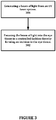
- FIG. 7 shows the proper immediate disposition of intraocular lens 408 once installed into capsule 402 with mating registration features edge 412 and incision 400 engaged, and resting upon surface 414.
- Major axis 404 and major axis 418 are not of equal length.
- Minor axis 406 and minor axis 420 are not the same length, either. This is done to accommodate the fact the capsule 402 may contract somewhat subsequent to capsulorhexis incision. The difference between the lengths of these axes is intended to allow the capsule 402 to contract and still better seat intraocular lens 408 into capsule 402 via incision 400. These differences should be limited to allow for reasonable contraction, but not so much as to allow for significant rotation of intraocular lens 408. Typical values for these length differences may range from 100 ⁇ m to 500 ⁇ m, for example.
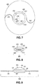
- FIG. 8 shows a side view on the same intraocular lens 408 depicted in FIGS. 6 and 7 .
- edge 412 is shown on the same side of optic 410 as surface 424 of intraocular lens 408.
- the surface 422 on intraocular lens 408 serves to maintain the integrity of fit between edge 412 and incision 400.
- Edge 412 is seen as the projection of surface 422 in the alternate view depicted in FIGS. 6 and 7 .
- Optical axis 411 of optic 410 is shown.
- Haptics 416 lie along the line of sight in this view.
- FIG. 9 is a side view of the lens configuration of FIG. 8 , but rotated 90 degrees to show that displaying surface 426 is not curved in both directions (i.e. shaped as a cylindrical lens).
- This cylindrical or toric optical system of optic 410 provides cylindrical correction for the astigmatism of a patient.
- Haptics 416 lie perpendicular to the line of sight in this view.
- the system can also be used to alter the structure of for example corneal tissue without generating a cavitation bubble as shown in Figure 16 .
- These alterations of the corneal tissue can be used to shape the refractive index profile of the cornea 504 itself as illustrated in Figure 18 .
- a multitude of small localized modifications 822 can be induced within the cornea which will change the refractive profile by altering the refractive index itself but also the mechanical strength of corneal tissue. So not only a change of index but also a change of corneal topography can be used. This is achieved by tightly controlling the lateral spacing of the laser effects utilizing beam deflection units 270 and focus shifting unit 704 through focusing unit 260.
- the method and system provide many advantages over the current standard of care. Specifically, rapid and precise openings in the lens capsule are enabled using a 320nm to 430nm laser to facilitate the placement and stability of intraocular lenses. But also the alteration of the refractive power of the corneal tissue by locally altering the refractive index and reshaping the corneal topography.
Landscapes
- Health & Medical Sciences (AREA)
- Ophthalmology & Optometry (AREA)
- Heart & Thoracic Surgery (AREA)
- Vascular Medicine (AREA)
- Optics & Photonics (AREA)
- Surgery (AREA)
- Engineering & Computer Science (AREA)
- Biomedical Technology (AREA)
- Physics & Mathematics (AREA)
- Nuclear Medicine, Radiotherapy & Molecular Imaging (AREA)
- Life Sciences & Earth Sciences (AREA)
- Animal Behavior & Ethology (AREA)
- General Health & Medical Sciences (AREA)
- Public Health (AREA)
- Veterinary Medicine (AREA)
- Prostheses (AREA)
- Laser Surgery Devices (AREA)
Applications Claiming Priority (3)
| Application Number | Priority Date | Filing Date | Title |
|---|---|---|---|
| US29335710P | 2010-01-08 | 2010-01-08 | |
| PCT/US2011/020610 WO2011085274A1 (en) | 2010-01-08 | 2011-01-07 | System for modifying eye tissue and intraocular lenses |
| EP11700479.6A EP2521520B1 (en) | 2010-01-08 | 2011-01-07 | System for modifying eye tissue and intraocular lenses |
Related Parent Applications (2)
| Application Number | Title | Priority Date | Filing Date |
|---|---|---|---|
| EP11700479.6A Division EP2521520B1 (en) | 2010-01-08 | 2011-01-07 | System for modifying eye tissue and intraocular lenses |
| EP11700479.6A Division-Into EP2521520B1 (en) | 2010-01-08 | 2011-01-07 | System for modifying eye tissue and intraocular lenses |
Publications (2)
| Publication Number | Publication Date |
|---|---|
| EP2774587A1 EP2774587A1 (en) | 2014-09-10 |
| EP2774587B1 true EP2774587B1 (en) | 2021-10-20 |
Family
ID=43806813
Family Applications (2)
| Application Number | Title | Priority Date | Filing Date |
|---|---|---|---|
| EP14164301.5A Active EP2774587B1 (en) | 2010-01-08 | 2011-01-07 | System for modifying eye tissue and intraocular lenses |
| EP11700479.6A Active EP2521520B1 (en) | 2010-01-08 | 2011-01-07 | System for modifying eye tissue and intraocular lenses |
Family Applications After (1)
| Application Number | Title | Priority Date | Filing Date |
|---|---|---|---|
| EP11700479.6A Active EP2521520B1 (en) | 2010-01-08 | 2011-01-07 | System for modifying eye tissue and intraocular lenses |
Country Status (6)
| Country | Link |
|---|---|
| US (3) | US9833358B2 (ja) |
| EP (2) | EP2774587B1 (ja) |
| JP (6) | JP5722345B2 (ja) |
| CN (1) | CN102791228B (ja) |
| AU (4) | AU2011203989B2 (ja) |
| WO (1) | WO2011085274A1 (ja) |
Families Citing this family (93)
| Publication number | Priority date | Publication date | Assignee | Title |
|---|---|---|---|---|
| US10842675B2 (en) | 2006-01-20 | 2020-11-24 | Lensar, Inc. | System and method for treating the structure of the human lens with a laser |
| US9889043B2 (en) * | 2006-01-20 | 2018-02-13 | Lensar, Inc. | System and apparatus for delivering a laser beam to the lens of an eye |
| US8480659B2 (en) | 2008-07-25 | 2013-07-09 | Lensar, Inc. | Method and system for removal and replacement of lens material from the lens of an eye |
| US8758332B2 (en) | 2009-07-24 | 2014-06-24 | Lensar, Inc. | Laser system and method for performing and sealing corneal incisions in the eye |
| US9833358B2 (en) | 2010-01-08 | 2017-12-05 | Optimedica Corporation | Method and system for modifying eye tissue and intraocular lenses |
| US10085886B2 (en) | 2010-01-08 | 2018-10-02 | Optimedica Corporation | Method and system for modifying eye tissue and intraocular lenses |
| EP2528563A4 (en) * | 2010-01-29 | 2014-06-18 | Lensar Inc | SERVO-CONTROLLED ANDOCKING DEVICE FOR USE IN EMERGENCY APPLICATIONS |
| US11771596B2 (en) | 2010-05-10 | 2023-10-03 | Ramot At Tel-Aviv University Ltd. | System and method for treating an eye |
| SG10201503532WA (en) | 2010-05-10 | 2015-06-29 | Univ Ramot | System for treating glaucoma by directing electromagnetic energy to the limbal area of an eye |
| AU2011295719B2 (en) | 2010-09-02 | 2014-07-10 | Amo Development, Llc | Patient interface for ophthalmologic diagnostic and interventional procedures |
| ES2937241T3 (es) | 2010-10-15 | 2023-03-27 | Lensar Inc | Sistema y método de iluminación controlada por barrido de estructuras dentro de un ojo |
| US10463541B2 (en) * | 2011-03-25 | 2019-11-05 | Lensar, Inc. | System and method for correcting astigmatism using multiple paired arcuate laser generated corneal incisions |
| EP3001944B1 (en) | 2011-06-23 | 2021-11-03 | AMO Development, LLC | Ophthalmic range finding |
| DE102011109058A1 (de) * | 2011-07-29 | 2013-01-31 | Carl Zeiss Meditec Ag | "Ophthalmologische Laservorrichtung und Verfahren zur Prävention und zur Behandlung von Nachstar" |
| WO2013049632A1 (en) * | 2011-09-29 | 2013-04-04 | Biolase, Inc. | Methods for treating eye conditions |
| US9044302B2 (en) | 2011-10-21 | 2015-06-02 | Optimedica Corp. | Patient interface for ophthalmologic diagnostic and interventional procedures |
| US8863749B2 (en) | 2011-10-21 | 2014-10-21 | Optimedica Corporation | Patient interface for ophthalmologic diagnostic and interventional procedures |
| US9237967B2 (en) | 2011-10-21 | 2016-01-19 | Optimedica Corporation | Patient interface for ophthalmologic diagnostic and interventional procedures |
| EP2633841B1 (de) * | 2012-02-28 | 2017-08-16 | Ziemer Ophthalmic Systems AG | Vorrichtung zur Behandlung von Augengewebe mittels gepulster Laserstrahlen |
| US9737438B2 (en) | 2012-03-14 | 2017-08-22 | Ziemer Ophthalmic Systems Ag | Device for processing eye tissue by means of pulsed laser beams |
| US20130289543A1 (en) * | 2012-04-23 | 2013-10-31 | David Haydn Mordaunt | System and method for in situ creation of a small aperture intraocular lens |
| EP2961364B1 (en) * | 2013-02-26 | 2020-05-06 | Belkin Laser Ltd. | System for glaucoma treatment |
| CA2904894C (en) | 2013-03-13 | 2021-07-27 | Optimedica Corporation | Free floating support for laser eye surgery system |
| CN105338932B (zh) | 2013-03-13 | 2017-07-04 | 光学医疗公司 | 用于激光手术系统的自由浮动式患者接口 |
| WO2014149832A1 (en) | 2013-03-15 | 2014-09-25 | Optimedica Corporation | Microfemtotomy methods and systems |
| WO2014172545A1 (en) | 2013-04-17 | 2014-10-23 | Optimedica Corporation | Laser fiducials for axis alignment in cataract surgery |
| JP6213714B2 (ja) * | 2013-06-27 | 2017-10-18 | 株式会社ニデック | 眼科用レーザ手術装置 |
| US10363173B2 (en) * | 2014-02-04 | 2019-07-30 | Optimedica Corporation | Confocal detection to minimize capsulotomy overcut while dynamically running on the capsular surface |
| AU2015214443B2 (en) * | 2014-02-04 | 2019-11-28 | Amo Development, Llc | Confocal detection to minimize capsulotomy overcut while dynamically running on the capsular surface |
| CN106163467B (zh) * | 2014-02-28 | 2018-08-10 | 易格赛尔透镜有限公司 | 激光辅助白内障手术 |
| US9820886B2 (en) | 2014-02-28 | 2017-11-21 | Excel-Lens, Inc. | Laser assisted cataract surgery |
| US10206817B2 (en) | 2014-02-28 | 2019-02-19 | Excel-Lens, Inc. | Laser assisted cataract surgery |
| US10327951B2 (en) | 2014-02-28 | 2019-06-25 | Excel-Lens, Inc. | Laser assisted cataract surgery |
| US10231872B2 (en) | 2014-02-28 | 2019-03-19 | Excel-Lens, Inc. | Laser assisted cataract surgery |
| EP2918252A1 (de) * | 2014-03-10 | 2015-09-16 | Schwind eye-tech-solutions GmbH & Co. KG | Vorrichtung zur Durchführung chirurgischer Behandlungen der Augenhornhaut |
| DE102014004026A1 (de) * | 2014-03-21 | 2015-09-24 | Carl Zeiss Meditec Ag | Ophthalmologische Vorrichtung zur Bearbeitung eines Gewebes im Vordergrund eines Auges |
| EP3122298B1 (en) | 2014-03-24 | 2021-02-17 | AMO Development, LLC | Automated calibration of laser system and tomography system with fluorescent imaging of scan pattern |
| US10441463B2 (en) | 2014-03-26 | 2019-10-15 | Optimedica Corporation | Confocal laser eye surgery system and improved confocal bypass assembly |
| US10441465B2 (en) | 2014-03-26 | 2019-10-15 | Optimedica Corporation | Registration of LOI fiducials with camera |
| EP4306036A3 (en) | 2014-03-26 | 2024-01-24 | AMO Development, LLC | Confocal laser eye surgery system |
| US9339414B2 (en) * | 2014-04-29 | 2016-05-17 | Chukyo Medical Co., Inc. | Irradiating device and program |
| US10268041B2 (en) * | 2014-05-24 | 2019-04-23 | Amalgamated Vision Llc | Wearable display for stereoscopic viewing |
| EP3191036B1 (en) | 2014-09-09 | 2024-04-10 | AMO Development, LLC | System for synchronized three-dimensional laser incisions |
| EP3954346B1 (en) | 2014-09-25 | 2024-03-20 | AMO Development, LLC | Systems for lenticular laser incision |
| US10709611B2 (en) | 2014-09-25 | 2020-07-14 | Amo Development, Llc | Systems and methods for lenticular laser incision |
| US10278864B2 (en) | 2014-10-22 | 2019-05-07 | Elwha Llc | Systems and methods for chromatic aberration correction |
| DE102015201647B4 (de) * | 2015-01-30 | 2017-09-28 | Asphericon Gmbh | Optisches Element zur Fokussierung kollimierter Strahlen sowie Verwendung dieses Elements |
| AU2015383858A1 (en) | 2015-02-26 | 2017-09-07 | Amo Development, Llc | Systems and methods for femtosecond laser photorefractive keratectomy |
| CN104741792B (zh) * | 2015-03-30 | 2017-03-15 | 江苏大学 | 一种实现激光高空化强化效率的装置和方法 |
| US10485705B2 (en) * | 2015-07-01 | 2019-11-26 | Optimedica Corporation | Sub-nanosecond laser cataract surgery system |
| US11083625B2 (en) * | 2015-07-01 | 2021-08-10 | Amo Development, Llc | Sub-nanosecond laser surgery system utilizing multiple pulsed laser beams |
| AU2015400412A1 (en) * | 2015-07-01 | 2018-01-18 | Optimedica Corporation | Sub-nanosecond laser cataract surgery system |
| WO2017007503A1 (en) | 2015-07-08 | 2017-01-12 | Optimedica Corporation | Laser surgical systems with laser scan location verification |
| DE102015009610A1 (de) | 2015-07-22 | 2017-01-26 | Carl Zeiss Meditec Ag | Post-operative Modifikation einer Intraokularlinse |
| EP3331481A1 (en) * | 2015-08-03 | 2018-06-13 | Optimedica Corporation | System for modifying eye tissue and intraocular lenses |
| KR20170062743A (ko) * | 2015-11-30 | 2017-06-08 | 전자부품연구원 | 가변초점 광학소자를 이용한 레이저 광원 셔터 시스템 |
| JP6836098B2 (ja) | 2015-12-29 | 2021-02-24 | 株式会社ニデック | 眼科用レーザ治療装置 |
| WO2017135035A1 (ja) * | 2016-02-03 | 2017-08-10 | 株式会社ニデック | 眼科用レーザ屈折矯正装置、眼科用フォトチューニング設定装置、眼科用フォトチューニングシステム、眼鏡用フォトチューニング設定装置、及びこれらに用いられるプログラム、眼科用レーザ手術装置 |
| AU2016405297B2 (en) | 2016-04-26 | 2022-02-03 | Amo Development, Llc | Registration of LOI fiducials with camera |
| AU2016409485B2 (en) | 2016-06-03 | 2022-11-24 | Amo Development, Llc | Free floating patient interface for laser surgery system |
| EP3474795A1 (en) | 2016-06-22 | 2019-05-01 | AMO Development, LLC | Improved methods for lenticular laser incision |
| CA3029425A1 (en) | 2016-06-29 | 2018-01-04 | Amo Development, Llc | Lenticular laser incision for low myopia and/or hyperopia patients |
| EP3481346B1 (en) | 2016-07-07 | 2020-10-21 | AMO Development, LLC | Lenticular laser incision using wavefront guided maps |
| KR101801028B1 (ko) * | 2016-07-11 | 2017-12-20 | 에이티아이 주식회사 | 3차원 가공대상체의 레이저 패터닝 장치 |
| US10973683B2 (en) | 2017-01-31 | 2021-04-13 | Amo Development, Llc | Methods and systems for laser ophthalmic surgery that provide for iris exposures below a predetermined exposure limit |
| KR102657761B1 (ko) * | 2017-08-18 | 2024-04-15 | 엘렉스 메디컬 피티와이 엘티디 | 다중 스폿 안과용 레이저 |
| US10792188B2 (en) | 2017-10-12 | 2020-10-06 | Amo Development, Llc | Systems and methods for high speed modulation of a resonant scanner in ophthalmic laser applications |
| US11529259B2 (en) | 2017-10-26 | 2022-12-20 | Amo Development, Llc | Femtosecond laser system and methods for photorefractive keratectomy |
| KR101888017B1 (ko) * | 2017-11-15 | 2018-09-20 | 에이티아이 주식회사 | 3차원 가공대상체의 레이저 패터닝 장치 및 방법 |
| US11135092B2 (en) * | 2017-12-12 | 2021-10-05 | Alcon Inc. | Multi-core fiber for a multi-spot laser probe |
| JP6644760B2 (ja) * | 2017-12-26 | 2020-02-12 | 株式会社ジェイメック | レーザ治療装置 |
| WO2019152045A1 (en) * | 2018-02-02 | 2019-08-08 | Xinova, LLC | Real-time treatment adjustment based on dosimetric data |
| WO2019191735A1 (en) * | 2018-03-30 | 2019-10-03 | Kendall Research Systems, LLC | An interleaved photon detection array for optically measuring a physical sample |
| WO2019193539A1 (en) * | 2018-04-06 | 2019-10-10 | Optimedica Corporation | Methods and systems for changing a refractive property of an implantable intraocular lens |
| EP3817698A4 (en) | 2018-07-02 | 2022-03-30 | Belkin Laser Ltd. | DIRECT SELECTIVE LASER TRABECULOPLASTY |
| DE102018118714A1 (de) * | 2018-08-01 | 2020-02-06 | Rowiak Gmbh | Vorrichtung und Verfahren zur Erzeugung einer Aperturblende in einer Intraokularlinse |
| US10842674B2 (en) | 2018-08-07 | 2020-11-24 | Amo Development, Llc | High speed corneal lenticular incision using a femtosecond laser |
| AU2019323793A1 (en) | 2018-08-22 | 2020-12-03 | Amo Development, Llc | Systems and methods for lenticular laser incision |
| US11039959B2 (en) | 2018-09-04 | 2021-06-22 | Amo Development, Llc | Ophthalmic laser surgical system and method for corneal lenticular incisions with unambiguous entry cuts |
| US10925723B2 (en) * | 2018-09-25 | 2021-02-23 | Gholam Peyman | Optical implant and methods of implantation |
| US11006823B2 (en) | 2019-01-28 | 2021-05-18 | Amo Development, Llc | Methods and systems for optical coherence tomography scanning of cornea and retina |
| US11110007B2 (en) | 2019-03-15 | 2021-09-07 | Amo Development, Llc | Ophthalmic laser surgical method and system for forming corneal lenticule with side tab for easy extraction |
| US11944574B2 (en) | 2019-04-05 | 2024-04-02 | Amo Groningen B.V. | Systems and methods for multiple layer intraocular lens and using refractive index writing |
| US11583389B2 (en) | 2019-04-05 | 2023-02-21 | Amo Groningen B.V. | Systems and methods for correcting photic phenomenon from an intraocular lens and using refractive index writing |
| US11583388B2 (en) | 2019-04-05 | 2023-02-21 | Amo Groningen B.V. | Systems and methods for spectacle independence using refractive index writing with an intraocular lens |
| US11564839B2 (en) | 2019-04-05 | 2023-01-31 | Amo Groningen B.V. | Systems and methods for vergence matching of an intraocular lens with refractive index writing |
| US11678975B2 (en) * | 2019-04-05 | 2023-06-20 | Amo Groningen B.V. | Systems and methods for treating ocular disease with an intraocular lens and refractive index writing |
| US11529230B2 (en) | 2019-04-05 | 2022-12-20 | Amo Groningen B.V. | Systems and methods for correcting power of an intraocular lens using refractive index writing |
| EP4028120A4 (en) * | 2019-09-12 | 2023-09-13 | Belkin Vision Ltd. | SELECTIVE LASER STIMULATION OF CORNEAL STEM CELLS |
| EP4054495A1 (en) | 2019-11-05 | 2022-09-14 | Vialase, Inc. | Surgical system and procedure for treatment of the trabecular meshwork and schlemm's canal using a femtosecond laser |
| CH717171A1 (de) * | 2020-02-26 | 2021-08-31 | Ziemer Ophthalmic Systems Ag | Vorrichtung zur Ablationsbearbeitung von ophthalmologischem Implantationsmaterial. |
| US11612315B2 (en) | 2020-04-09 | 2023-03-28 | Vialase, Inc. | Alignment and diagnostic device and methods for imaging and surgery at the irido-corneal angle of the eye |
| IL297873A (en) * | 2020-07-19 | 2023-01-01 | Belkin Vision Ltd | Automatic capsulotomy |
Family Cites Families (60)
| Publication number | Priority date | Publication date | Assignee | Title |
|---|---|---|---|---|
| US4784135A (en) | 1982-12-09 | 1988-11-15 | International Business Machines Corporation | Far ultraviolet surgical and dental procedures |
| US4732148A (en) * | 1983-11-17 | 1988-03-22 | Lri L.P. | Method for performing ophthalmic laser surgery |
| ZA864253B (en) * | 1985-06-06 | 1987-02-25 | Francis A L Esperance | Apparatus for ophthalmological surgery |
| US5984916A (en) * | 1993-04-20 | 1999-11-16 | Lai; Shui T. | Ophthalmic surgical laser and method |
| US5993438A (en) * | 1993-11-12 | 1999-11-30 | Escalon Medical Corporation | Intrastromal photorefractive keratectomy |
| CA2127029C (en) * | 1993-11-12 | 2003-08-19 | Tibor Juhasz | Intrastromal photorefractive keratectomy |
| US5743902A (en) | 1995-01-23 | 1998-04-28 | Coherent, Inc. | Hand-held laser scanner |
| US6454761B1 (en) | 1995-01-30 | 2002-09-24 | Philip D. Freedman | Laser surgery device and method |
| US5720894A (en) | 1996-01-11 | 1998-02-24 | The Regents Of The University Of California | Ultrashort pulse high repetition rate laser system for biological tissue processing |
| US7655002B2 (en) | 1996-03-21 | 2010-02-02 | Second Sight Laser Technologies, Inc. | Lenticular refractive surgery of presbyopia, other refractive errors, and cataract retardation |
| US6019472A (en) | 1997-05-12 | 2000-02-01 | Koester; Charles J. | Contact lens element for examination or treatment of ocular tissues |
| DE19837932C2 (de) | 1998-08-20 | 2000-09-07 | Bioshape Ag | Verfahren und Vorrichtung zur Ermittlung der Oberflächenform von biologischem Gewebe |
| DE19855623C1 (de) * | 1998-12-02 | 2000-02-24 | Lpkf Laser & Electronics Ag | Verfahren zur Erzeugung einer Markierung in einem Glaskörper |
| US20010029363A1 (en) * | 1999-05-03 | 2001-10-11 | Lin J. T. | Methods and apparatus for presbyopia correction using ultraviolet and infrared lasers |
| US6949093B1 (en) * | 2000-03-21 | 2005-09-27 | Minu, L.L.C. | Adjustable universal implant blank for modifying corneal curvature and methods of modifying corneal curvature therewith |
| WO2001091661A1 (en) * | 2000-06-01 | 2001-12-06 | The General Hospital Corporation | Selective photocoagulation |
| DE60133656T2 (de) | 2000-09-26 | 2009-06-25 | Calhoun Vision Inc., Pasadena | Leistungsanpassung für anpassbare linse |
| US6989007B2 (en) * | 2001-02-21 | 2006-01-24 | Solx, Inc. | Devices and techniques for treating glaucoma |
| EP1372552B1 (de) * | 2001-03-27 | 2017-03-01 | WaveLight GmbH | Vorrichtung zur bearbeitung und diagnose von augengewebe |
| US6579282B2 (en) | 2001-04-25 | 2003-06-17 | 20/10 Perfect Vision Optische Geraete Gmbh | Device and method for creating a corneal reference for an eyetracker |
| US6610051B2 (en) * | 2001-10-12 | 2003-08-26 | 20/10 Perfect Vision Optische Geraete Gmbh | Device and method for performing refractive surgery |
| EP1354573A1 (en) * | 2002-04-08 | 2003-10-22 | Lumenis Inc. | System, method and apparatus for providing uniform illumination |
| US7133137B2 (en) | 2002-06-27 | 2006-11-07 | Visx, Incorporated | Integrated scanning and ocular tomography system and method |
| US6855163B2 (en) | 2002-07-19 | 2005-02-15 | Minu, Llc | Gradual correction of corneal refractive error using multiple inlays |
| DE10323422B4 (de) * | 2002-08-23 | 2022-05-05 | Carl Zeiss Meditec Ag | Vorrichtung und Verfahren zur Messung eines optischen Durchbruchs in einem Gewebe |
| US7351241B2 (en) * | 2003-06-02 | 2008-04-01 | Carl Zeiss Meditec Ag | Method and apparatus for precision working of material |
| JP2006528508A (ja) * | 2003-07-25 | 2006-12-21 | コーニンクレッカ フィリップス エレクトロニクス エヌ ヴィ | 管内で測定を実行する手段 |
| AU2005234778B2 (en) | 2004-04-20 | 2011-04-21 | Alcon Inc. | Integrated surgical microscope and wavefront sensor |
| US8394084B2 (en) * | 2005-01-10 | 2013-03-12 | Optimedica Corporation | Apparatus for patterned plasma-mediated laser trephination of the lens capsule and three dimensional phaco-segmentation |
| ES2374819T3 (es) | 2005-11-17 | 2012-02-22 | Wavelight Gmbh | Disposición para realizar tratamientos quirúrgicos con láser del ojo. |
| US8262646B2 (en) * | 2006-01-20 | 2012-09-11 | Lensar, Inc. | System and method for providing the shaped structural weakening of the human lens with a laser |
| WO2008014419A2 (en) * | 2006-07-26 | 2008-01-31 | Lai Shui T | Intrastromal surgery correcting low order and high order aberrations of the eye |
| US20080027519A1 (en) * | 2006-07-28 | 2008-01-31 | Guerrero John M | Method of treatment of ocular compartment syndromes |
| DE102006036800A1 (de) * | 2006-08-07 | 2008-02-14 | Carl Zeiss Meditec Ag | Vorrichtung zur individuellen Therapieplanung und positionsgenauen Modifikation eines optischen Elements |
| RU2460503C2 (ru) | 2006-11-10 | 2012-09-10 | Ларс Михаэль ЛАРСЕН | Способ и устройство для неразрушающей или минимально разрушающей световой обработки глаза |
| US8088124B2 (en) * | 2007-01-19 | 2012-01-03 | Technolas Perfect Vision Gmbh | System and method for precise beam positioning in ocular surgery |
| US20110319875A1 (en) | 2007-01-19 | 2011-12-29 | Frieder Loesel | Apparatus and Method for Morphing a Three-Dimensional Target Surface into a Two-Dimensional Image for Use in Guiding a Laser Beam in Ocular Surgery |
| AU2008255642B2 (en) * | 2007-05-30 | 2013-03-07 | Alpharet Pty Ltd | Retinal rejuvenation laser |
| DE102007028042B3 (de) | 2007-06-14 | 2008-08-07 | Universität Zu Lübeck | Verfahren zur Laserbearbeitung transparenter Materialien |
| US8486055B2 (en) | 2007-06-26 | 2013-07-16 | Bausch & Lomb Incorporated | Method for modifying the refractive index of ocular tissues |
| WO2009033110A2 (en) * | 2007-09-05 | 2009-03-12 | Lensx Lasers, Inc. | Laser-induced protection shield in laser surgery |
| JP2010538699A (ja) * | 2007-09-06 | 2010-12-16 | アルコン レンゼックス, インコーポレーテッド | 水晶体の光破壊治療 |
| US20090149841A1 (en) * | 2007-09-10 | 2009-06-11 | Kurtz Ronald M | Effective Laser Photodisruptive Surgery in a Gravity Field |
| WO2009036098A2 (en) * | 2007-09-10 | 2009-03-19 | Lensx Lasers, Inc. | Apparatus, systems and techniques for interfacing with an eye in laser surgery |
| US20090118716A1 (en) * | 2007-11-07 | 2009-05-07 | Intralase, Inc. | System and method for scanning a pulsed laser beam |
| US8142423B2 (en) * | 2007-11-07 | 2012-03-27 | Amo Development, Llc. | System and method for incising material |
| US7717907B2 (en) | 2007-12-17 | 2010-05-18 | Technolas Perfect Vision Gmbh | Method for intrastromal refractive surgery |
| CN101951990A (zh) * | 2007-12-23 | 2011-01-19 | Oraya治疗公司 | 检测、控制和预测辐射传输的方法和装置 |
| ES2757628T3 (es) * | 2008-01-09 | 2020-04-29 | Alcon Inc | Fragmentación de tejido curvada mediante láser fotodisruptivo |
| DE102008005053A1 (de) * | 2008-01-18 | 2009-07-30 | Rowiak Gmbh | Laserkorrektur von Sehfehlern an der natürlichen Augenlinse |
| US8231673B2 (en) | 2008-05-06 | 2012-07-31 | Novartis Ag | Non-invasive power adjustable intraocular lens |
| WO2010085650A2 (en) * | 2009-01-23 | 2010-07-29 | The General Hospital Corporation | Dose determination for inducing microcavitation in retinal pigment epithelium (rpe) |
| US8382745B2 (en) | 2009-07-24 | 2013-02-26 | Lensar, Inc. | Laser system and method for astigmatic corrections in association with cataract treatment |
| US8920407B2 (en) * | 2009-07-29 | 2014-12-30 | Alcon Lensx, Inc. | Optical system for ophthalmic surgical laser |
| US8574224B2 (en) * | 2009-10-23 | 2013-11-05 | Tarek A. Shazly | Surgical laser device utilizing a visible laser diode |
| US9833358B2 (en) | 2010-01-08 | 2017-12-05 | Optimedica Corporation | Method and system for modifying eye tissue and intraocular lenses |
| US8414564B2 (en) | 2010-02-18 | 2013-04-09 | Alcon Lensx, Inc. | Optical coherence tomographic system for ophthalmic surgery |
| US8845624B2 (en) | 2010-06-25 | 2014-09-30 | Alcon LexSx, Inc. | Adaptive patient interface |
| DE102011085046A1 (de) | 2011-10-21 | 2013-04-25 | Carl Zeiss Meditec Ag | Erzeugung von Schnittflächen in einem transparenten Material mittels optischer Strahlung |
| JP6257549B2 (ja) | 2015-03-25 | 2018-01-10 | サンスター株式会社 | 水系口腔用組成物 |
-
2011
- 2011-01-07 US US12/987,069 patent/US9833358B2/en active Active
- 2011-01-07 CN CN201180013276.8A patent/CN102791228B/zh not_active Expired - Fee Related
- 2011-01-07 JP JP2012548195A patent/JP5722345B2/ja active Active
- 2011-01-07 EP EP14164301.5A patent/EP2774587B1/en active Active
- 2011-01-07 AU AU2011203989A patent/AU2011203989B2/en not_active Ceased
- 2011-01-07 WO PCT/US2011/020610 patent/WO2011085274A1/en active Application Filing
- 2011-01-07 EP EP11700479.6A patent/EP2521520B1/en active Active
-
2015
- 2015-03-25 JP JP2015062514A patent/JP5977390B2/ja not_active Expired - Fee Related
- 2015-07-14 AU AU2015204287A patent/AU2015204287B2/en not_active Ceased
-
2016
- 2016-07-21 JP JP2016143124A patent/JP6266713B2/ja active Active
- 2016-07-21 JP JP2016143123A patent/JP6266712B2/ja active Active
-
2017
- 2017-05-09 AU AU2017203081A patent/AU2017203081B2/en not_active Ceased
- 2017-12-04 US US15/830,883 patent/US11058583B2/en active Active
- 2017-12-04 US US15/831,032 patent/US10864114B2/en active Active
- 2017-12-20 JP JP2017243372A patent/JP6487023B2/ja active Active
- 2017-12-20 JP JP2017243373A patent/JP6487024B2/ja active Active
-
2018
- 2018-12-20 AU AU2018282406A patent/AU2018282406B2/en not_active Ceased
Non-Patent Citations (1)
| Title |
|---|
| None * |
Also Published As
| Publication number | Publication date |
|---|---|
| US11058583B2 (en) | 2021-07-13 |
| EP2521520A1 (en) | 2012-11-14 |
| AU2015204287B2 (en) | 2017-03-30 |
| AU2017203081A1 (en) | 2017-06-22 |
| JP2016195822A (ja) | 2016-11-24 |
| JP2016195823A (ja) | 2016-11-24 |
| AU2011203989A1 (en) | 2012-07-26 |
| WO2011085274A1 (en) | 2011-07-14 |
| JP2018075404A (ja) | 2018-05-17 |
| AU2011203989B2 (en) | 2015-06-11 |
| JP6487023B2 (ja) | 2019-03-20 |
| CN102791228B (zh) | 2016-05-11 |
| US20110172649A1 (en) | 2011-07-14 |
| JP2018075403A (ja) | 2018-05-17 |
| US10864114B2 (en) | 2020-12-15 |
| AU2018282406B2 (en) | 2020-03-12 |
| US20180085253A1 (en) | 2018-03-29 |
| CN102791228A (zh) | 2012-11-21 |
| AU2017203081B2 (en) | 2018-10-04 |
| JP6266713B2 (ja) | 2018-01-24 |
| US20180085252A1 (en) | 2018-03-29 |
| JP2013516294A (ja) | 2013-05-13 |
| JP2015163193A (ja) | 2015-09-10 |
| JP5977390B2 (ja) | 2016-08-24 |
| EP2774587A1 (en) | 2014-09-10 |
| EP2521520B1 (en) | 2017-08-16 |
| JP5722345B2 (ja) | 2015-05-20 |
| JP6266712B2 (ja) | 2018-01-24 |
| JP6487024B2 (ja) | 2019-03-20 |
| AU2018282406A1 (en) | 2019-01-17 |
| AU2015204287A1 (en) | 2015-09-03 |
| US9833358B2 (en) | 2017-12-05 |
Similar Documents
| Publication | Publication Date | Title |
|---|---|---|
| AU2018282406B2 (en) | System for modifying eye tissue and intraocular lenses | |
| US20200390597A1 (en) | Method and system for modifying eye tissue and intraocular lenses | |
| US9668919B2 (en) | System and method for plasma-mediated modification of tissue | |
| AU2015404411B2 (en) | System for modifying eye tissue and intraocular lenses |
Legal Events
| Date | Code | Title | Description |
|---|---|---|---|
| PUAI | Public reference made under article 153(3) epc to a published international application that has entered the european phase |
Free format text: ORIGINAL CODE: 0009012 |
|
| 17P | Request for examination filed |
Effective date: 20140410 |
|
| AC | Divisional application: reference to earlier application |
Ref document number: 2521520 Country of ref document: EP Kind code of ref document: P |
|
| AK | Designated contracting states |
Kind code of ref document: A1 Designated state(s): AL AT BE BG CH CY CZ DE DK EE ES FI FR GB GR HR HU IE IS IT LI LT LU LV MC MK MT NL NO PL PT RO RS SE SI SK SM TR |
|
| R17P | Request for examination filed (corrected) |
Effective date: 20150128 |
|
| RBV | Designated contracting states (corrected) |
Designated state(s): AL AT BE BG CH CY CZ DE DK EE ES FI FR GB GR HR HU IE IS IT LI LT LU LV MC MK MT NL NO PL PT RO RS SE SI SK SM TR |
|
| STAA | Information on the status of an ep patent application or granted ep patent |
Free format text: STATUS: EXAMINATION IS IN PROGRESS |
|
| 17Q | First examination report despatched |
Effective date: 20171124 |
|
| STAA | Information on the status of an ep patent application or granted ep patent |
Free format text: STATUS: EXAMINATION IS IN PROGRESS |
|
| GRAP | Despatch of communication of intention to grant a patent |
Free format text: ORIGINAL CODE: EPIDOSNIGR1 |
|
| STAA | Information on the status of an ep patent application or granted ep patent |
Free format text: STATUS: GRANT OF PATENT IS INTENDED |
|
| INTG | Intention to grant announced |
Effective date: 20200608 |
|
| RAP1 | Party data changed (applicant data changed or rights of an application transferred) |
Owner name: AMO DEVELOPMENT, LLC |
|
| GRAJ | Information related to disapproval of communication of intention to grant by the applicant or resumption of examination proceedings by the epo deleted |
Free format text: ORIGINAL CODE: EPIDOSDIGR1 |
|
| STAA | Information on the status of an ep patent application or granted ep patent |
Free format text: STATUS: EXAMINATION IS IN PROGRESS |
|
| INTC | Intention to grant announced (deleted) | ||
| GRAP | Despatch of communication of intention to grant a patent |
Free format text: ORIGINAL CODE: EPIDOSNIGR1 |
|
| STAA | Information on the status of an ep patent application or granted ep patent |
Free format text: STATUS: GRANT OF PATENT IS INTENDED |
|
| INTG | Intention to grant announced |
Effective date: 20210622 |
|
| RIN1 | Information on inventor provided before grant (corrected) |
Inventor name: SCHUELE, GEORG Inventor name: ANDERSEN, DAN E. |
|
| GRAS | Grant fee paid |
Free format text: ORIGINAL CODE: EPIDOSNIGR3 |
|
| GRAA | (expected) grant |
Free format text: ORIGINAL CODE: 0009210 |
|
| STAA | Information on the status of an ep patent application or granted ep patent |
Free format text: STATUS: THE PATENT HAS BEEN GRANTED |
|
| AC | Divisional application: reference to earlier application |
Ref document number: 2521520 Country of ref document: EP Kind code of ref document: P |
|
| AK | Designated contracting states |
Kind code of ref document: B1 Designated state(s): AL AT BE BG CH CY CZ DE DK EE ES FI FR GB GR HR HU IE IS IT LI LT LU LV MC MK MT NL NO PL PT RO RS SE SI SK SM TR |
|
| REG | Reference to a national code |
Ref country code: GB Ref legal event code: FG4D |
|
| REG | Reference to a national code |
Ref country code: CH Ref legal event code: EP |
|
| REG | Reference to a national code |
Ref country code: IE Ref legal event code: FG4D |
|
| REG | Reference to a national code |
Ref country code: DE Ref legal event code: R096 Ref document number: 602011071981 Country of ref document: DE |
|
| REG | Reference to a national code |
Ref country code: AT Ref legal event code: REF Ref document number: 1439304 Country of ref document: AT Kind code of ref document: T Effective date: 20211115 |
|
| REG | Reference to a national code |
Ref country code: NL Ref legal event code: FP |
|
| PGFP | Annual fee paid to national office [announced via postgrant information from national office to epo] |
Ref country code: GB Payment date: 20211203 Year of fee payment: 12 |
|
| REG | Reference to a national code |
Ref country code: LT Ref legal event code: MG9D |
|
| PGFP | Annual fee paid to national office [announced via postgrant information from national office to epo] |
Ref country code: CH Payment date: 20211216 Year of fee payment: 12 |
|
| REG | Reference to a national code |
Ref country code: AT Ref legal event code: MK05 Ref document number: 1439304 Country of ref document: AT Kind code of ref document: T Effective date: 20211020 |
|
| PGFP | Annual fee paid to national office [announced via postgrant information from national office to epo] |
Ref country code: NL Payment date: 20211216 Year of fee payment: 12 |
|
| PG25 | Lapsed in a contracting state [announced via postgrant information from national office to epo] |
Ref country code: RS Free format text: LAPSE BECAUSE OF FAILURE TO SUBMIT A TRANSLATION OF THE DESCRIPTION OR TO PAY THE FEE WITHIN THE PRESCRIBED TIME-LIMIT Effective date: 20211020 Ref country code: LT Free format text: LAPSE BECAUSE OF FAILURE TO SUBMIT A TRANSLATION OF THE DESCRIPTION OR TO PAY THE FEE WITHIN THE PRESCRIBED TIME-LIMIT Effective date: 20211020 Ref country code: FI Free format text: LAPSE BECAUSE OF FAILURE TO SUBMIT A TRANSLATION OF THE DESCRIPTION OR TO PAY THE FEE WITHIN THE PRESCRIBED TIME-LIMIT Effective date: 20211020 Ref country code: BG Free format text: LAPSE BECAUSE OF FAILURE TO SUBMIT A TRANSLATION OF THE DESCRIPTION OR TO PAY THE FEE WITHIN THE PRESCRIBED TIME-LIMIT Effective date: 20220120 Ref country code: AT Free format text: LAPSE BECAUSE OF FAILURE TO SUBMIT A TRANSLATION OF THE DESCRIPTION OR TO PAY THE FEE WITHIN THE PRESCRIBED TIME-LIMIT Effective date: 20211020 |
|
| PG25 | Lapsed in a contracting state [announced via postgrant information from national office to epo] |
Ref country code: IS Free format text: LAPSE BECAUSE OF FAILURE TO SUBMIT A TRANSLATION OF THE DESCRIPTION OR TO PAY THE FEE WITHIN THE PRESCRIBED TIME-LIMIT Effective date: 20220220 Ref country code: SE Free format text: LAPSE BECAUSE OF FAILURE TO SUBMIT A TRANSLATION OF THE DESCRIPTION OR TO PAY THE FEE WITHIN THE PRESCRIBED TIME-LIMIT Effective date: 20211020 Ref country code: PT Free format text: LAPSE BECAUSE OF FAILURE TO SUBMIT A TRANSLATION OF THE DESCRIPTION OR TO PAY THE FEE WITHIN THE PRESCRIBED TIME-LIMIT Effective date: 20220221 Ref country code: PL Free format text: LAPSE BECAUSE OF FAILURE TO SUBMIT A TRANSLATION OF THE DESCRIPTION OR TO PAY THE FEE WITHIN THE PRESCRIBED TIME-LIMIT Effective date: 20211020 Ref country code: NO Free format text: LAPSE BECAUSE OF FAILURE TO SUBMIT A TRANSLATION OF THE DESCRIPTION OR TO PAY THE FEE WITHIN THE PRESCRIBED TIME-LIMIT Effective date: 20220120 Ref country code: LV Free format text: LAPSE BECAUSE OF FAILURE TO SUBMIT A TRANSLATION OF THE DESCRIPTION OR TO PAY THE FEE WITHIN THE PRESCRIBED TIME-LIMIT Effective date: 20211020 Ref country code: HR Free format text: LAPSE BECAUSE OF FAILURE TO SUBMIT A TRANSLATION OF THE DESCRIPTION OR TO PAY THE FEE WITHIN THE PRESCRIBED TIME-LIMIT Effective date: 20211020 Ref country code: GR Free format text: LAPSE BECAUSE OF FAILURE TO SUBMIT A TRANSLATION OF THE DESCRIPTION OR TO PAY THE FEE WITHIN THE PRESCRIBED TIME-LIMIT Effective date: 20220121 Ref country code: ES Free format text: LAPSE BECAUSE OF FAILURE TO SUBMIT A TRANSLATION OF THE DESCRIPTION OR TO PAY THE FEE WITHIN THE PRESCRIBED TIME-LIMIT Effective date: 20211020 |
|
| REG | Reference to a national code |
Ref country code: DE Ref legal event code: R097 Ref document number: 602011071981 Country of ref document: DE |
|
| PG25 | Lapsed in a contracting state [announced via postgrant information from national office to epo] |
Ref country code: SM Free format text: LAPSE BECAUSE OF FAILURE TO SUBMIT A TRANSLATION OF THE DESCRIPTION OR TO PAY THE FEE WITHIN THE PRESCRIBED TIME-LIMIT Effective date: 20211020 Ref country code: SK Free format text: LAPSE BECAUSE OF FAILURE TO SUBMIT A TRANSLATION OF THE DESCRIPTION OR TO PAY THE FEE WITHIN THE PRESCRIBED TIME-LIMIT Effective date: 20211020 Ref country code: RO Free format text: LAPSE BECAUSE OF FAILURE TO SUBMIT A TRANSLATION OF THE DESCRIPTION OR TO PAY THE FEE WITHIN THE PRESCRIBED TIME-LIMIT Effective date: 20211020 Ref country code: EE Free format text: LAPSE BECAUSE OF FAILURE TO SUBMIT A TRANSLATION OF THE DESCRIPTION OR TO PAY THE FEE WITHIN THE PRESCRIBED TIME-LIMIT Effective date: 20211020 Ref country code: DK Free format text: LAPSE BECAUSE OF FAILURE TO SUBMIT A TRANSLATION OF THE DESCRIPTION OR TO PAY THE FEE WITHIN THE PRESCRIBED TIME-LIMIT Effective date: 20211020 Ref country code: CZ Free format text: LAPSE BECAUSE OF FAILURE TO SUBMIT A TRANSLATION OF THE DESCRIPTION OR TO PAY THE FEE WITHIN THE PRESCRIBED TIME-LIMIT Effective date: 20211020 |
|
| PLBE | No opposition filed within time limit |
Free format text: ORIGINAL CODE: 0009261 |
|
| STAA | Information on the status of an ep patent application or granted ep patent |
Free format text: STATUS: NO OPPOSITION FILED WITHIN TIME LIMIT |
|
| PG25 | Lapsed in a contracting state [announced via postgrant information from national office to epo] |
Ref country code: MC Free format text: LAPSE BECAUSE OF FAILURE TO SUBMIT A TRANSLATION OF THE DESCRIPTION OR TO PAY THE FEE WITHIN THE PRESCRIBED TIME-LIMIT Effective date: 20211020 |
|
| 26N | No opposition filed |
Effective date: 20220721 |
|
| REG | Reference to a national code |
Ref country code: BE Ref legal event code: MM Effective date: 20220131 |
|
| PG25 | Lapsed in a contracting state [announced via postgrant information from national office to epo] |
Ref country code: LU Free format text: LAPSE BECAUSE OF NON-PAYMENT OF DUE FEES Effective date: 20220107 Ref country code: AL Free format text: LAPSE BECAUSE OF FAILURE TO SUBMIT A TRANSLATION OF THE DESCRIPTION OR TO PAY THE FEE WITHIN THE PRESCRIBED TIME-LIMIT Effective date: 20211020 |
|
| PG25 | Lapsed in a contracting state [announced via postgrant information from national office to epo] |
Ref country code: SI Free format text: LAPSE BECAUSE OF FAILURE TO SUBMIT A TRANSLATION OF THE DESCRIPTION OR TO PAY THE FEE WITHIN THE PRESCRIBED TIME-LIMIT Effective date: 20211020 Ref country code: BE Free format text: LAPSE BECAUSE OF NON-PAYMENT OF DUE FEES Effective date: 20220131 |
|
| PG25 | Lapsed in a contracting state [announced via postgrant information from national office to epo] |
Ref country code: IE Free format text: LAPSE BECAUSE OF NON-PAYMENT OF DUE FEES Effective date: 20220107 |
|
| PG25 | Lapsed in a contracting state [announced via postgrant information from national office to epo] |
Ref country code: IT Free format text: LAPSE BECAUSE OF FAILURE TO SUBMIT A TRANSLATION OF THE DESCRIPTION OR TO PAY THE FEE WITHIN THE PRESCRIBED TIME-LIMIT Effective date: 20211020 |
|
| REG | Reference to a national code |
Ref country code: CH Ref legal event code: PL |
|
| REG | Reference to a national code |
Ref country code: NL Ref legal event code: MM Effective date: 20230201 |
|
| GBPC | Gb: european patent ceased through non-payment of renewal fee |
Effective date: 20230107 |
|
| PG25 | Lapsed in a contracting state [announced via postgrant information from national office to epo] |
Ref country code: NL Free format text: LAPSE BECAUSE OF NON-PAYMENT OF DUE FEES Effective date: 20230201 Ref country code: LI Free format text: LAPSE BECAUSE OF NON-PAYMENT OF DUE FEES Effective date: 20230131 Ref country code: GB Free format text: LAPSE BECAUSE OF NON-PAYMENT OF DUE FEES Effective date: 20230107 Ref country code: CH Free format text: LAPSE BECAUSE OF NON-PAYMENT OF DUE FEES Effective date: 20230131 |
|
| PGFP | Annual fee paid to national office [announced via postgrant information from national office to epo] |
Ref country code: FR Payment date: 20231212 Year of fee payment: 14 |
|
| PG25 | Lapsed in a contracting state [announced via postgrant information from national office to epo] |
Ref country code: HU Free format text: LAPSE BECAUSE OF FAILURE TO SUBMIT A TRANSLATION OF THE DESCRIPTION OR TO PAY THE FEE WITHIN THE PRESCRIBED TIME-LIMIT; INVALID AB INITIO Effective date: 20110107 |
|
| PG25 | Lapsed in a contracting state [announced via postgrant information from national office to epo] |
Ref country code: MK Free format text: LAPSE BECAUSE OF FAILURE TO SUBMIT A TRANSLATION OF THE DESCRIPTION OR TO PAY THE FEE WITHIN THE PRESCRIBED TIME-LIMIT Effective date: 20211020 Ref country code: CY Free format text: LAPSE BECAUSE OF FAILURE TO SUBMIT A TRANSLATION OF THE DESCRIPTION OR TO PAY THE FEE WITHIN THE PRESCRIBED TIME-LIMIT Effective date: 20211020 |
|
| PGFP | Annual fee paid to national office [announced via postgrant information from national office to epo] |
Ref country code: DE Payment date: 20231128 Year of fee payment: 14 |