EP2774438B1 - Configurations de dmrs pour la communication multipoint coordonnée - Google Patents
Configurations de dmrs pour la communication multipoint coordonnée Download PDFInfo
- Publication number
- EP2774438B1 EP2774438B1 EP12846276.9A EP12846276A EP2774438B1 EP 2774438 B1 EP2774438 B1 EP 2774438B1 EP 12846276 A EP12846276 A EP 12846276A EP 2774438 B1 EP2774438 B1 EP 2774438B1
- Authority
- EP
- European Patent Office
- Prior art keywords
- mobile device
- sequence
- cyclic shift
- indication
- specific
- Prior art date
- Legal status (The legal status is an assumption and is not a legal conclusion. Google has not performed a legal analysis and makes no representation as to the accuracy of the status listed.)
- Active
Links
- 238000004891 communication Methods 0.000 title description 39
- 125000004122 cyclic group Chemical group 0.000 claims description 101
- 238000000034 method Methods 0.000 claims description 78
- 108010076504 Protein Sorting Signals Proteins 0.000 claims description 29
- 230000001419 dependent effect Effects 0.000 claims description 5
- 230000005540 biological transmission Effects 0.000 description 49
- 230000015654 memory Effects 0.000 description 39
- 238000004590 computer program Methods 0.000 description 23
- 230000006870 function Effects 0.000 description 14
- 238000003860 storage Methods 0.000 description 12
- 238000012545 processing Methods 0.000 description 9
- 238000013461 design Methods 0.000 description 8
- 238000010586 diagram Methods 0.000 description 6
- 239000004065 semiconductor Substances 0.000 description 6
- 230000002776 aggregation Effects 0.000 description 5
- 238000004220 aggregation Methods 0.000 description 5
- 230000008901 benefit Effects 0.000 description 5
- 239000000969 carrier Substances 0.000 description 5
- 101150071746 Pbsn gene Proteins 0.000 description 4
- 238000005516 engineering process Methods 0.000 description 4
- 239000010410 layer Substances 0.000 description 4
- 238000007726 management method Methods 0.000 description 3
- 230000008569 process Effects 0.000 description 3
- 230000006978 adaptation Effects 0.000 description 2
- 230000002457 bidirectional effect Effects 0.000 description 2
- 238000000794 confocal Raman spectroscopy Methods 0.000 description 2
- 230000008878 coupling Effects 0.000 description 2
- 238000010168 coupling process Methods 0.000 description 2
- 238000005859 coupling reaction Methods 0.000 description 2
- 238000011500 cytoreductive surgery Methods 0.000 description 2
- 239000002355 dual-layer Substances 0.000 description 2
- 238000004519 manufacturing process Methods 0.000 description 2
- 239000011159 matrix material Substances 0.000 description 2
- 238000005259 measurement Methods 0.000 description 2
- 238000012986 modification Methods 0.000 description 2
- 230000004048 modification Effects 0.000 description 2
- 230000003287 optical effect Effects 0.000 description 2
- 230000011664 signaling Effects 0.000 description 2
- 238000001228 spectrum Methods 0.000 description 2
- 230000003321 amplification Effects 0.000 description 1
- 230000009286 beneficial effect Effects 0.000 description 1
- 238000004364 calculation method Methods 0.000 description 1
- 230000010267 cellular communication Effects 0.000 description 1
- 230000001413 cellular effect Effects 0.000 description 1
- 230000006835 compression Effects 0.000 description 1
- 238000007906 compression Methods 0.000 description 1
- 239000004020 conductor Substances 0.000 description 1
- 238000013500 data storage Methods 0.000 description 1
- 230000007774 longterm Effects 0.000 description 1
- 238000012423 maintenance Methods 0.000 description 1
- 238000013507 mapping Methods 0.000 description 1
- 238000010295 mobile communication Methods 0.000 description 1
- 230000008450 motivation Effects 0.000 description 1
- 238000003199 nucleic acid amplification method Methods 0.000 description 1
- 239000013307 optical fiber Substances 0.000 description 1
- 230000005236 sound signal Effects 0.000 description 1
- 239000000758 substrate Substances 0.000 description 1
Images


Classifications
-
- H—ELECTRICITY
- H04—ELECTRIC COMMUNICATION TECHNIQUE
- H04L—TRANSMISSION OF DIGITAL INFORMATION, e.g. TELEGRAPHIC COMMUNICATION
- H04L5/00—Arrangements affording multiple use of the transmission path
- H04L5/003—Arrangements for allocating sub-channels of the transmission path
- H04L5/0048—Allocation of pilot signals, i.e. of signals known to the receiver
- H04L5/0051—Allocation of pilot signals, i.e. of signals known to the receiver of dedicated pilots, i.e. pilots destined for a single user or terminal
-
- H—ELECTRICITY
- H04—ELECTRIC COMMUNICATION TECHNIQUE
- H04L—TRANSMISSION OF DIGITAL INFORMATION, e.g. TELEGRAPHIC COMMUNICATION
- H04L27/00—Modulated-carrier systems
- H04L27/26—Systems using multi-frequency codes
- H04L27/2601—Multicarrier modulation systems
- H04L27/2602—Signal structure
- H04L27/261—Details of reference signals
- H04L27/2613—Structure of the reference signals
-
- H—ELECTRICITY
- H04—ELECTRIC COMMUNICATION TECHNIQUE
- H04L—TRANSMISSION OF DIGITAL INFORMATION, e.g. TELEGRAPHIC COMMUNICATION
- H04L5/00—Arrangements affording multiple use of the transmission path
- H04L5/003—Arrangements for allocating sub-channels of the transmission path
- H04L5/0032—Distributed allocation, i.e. involving a plurality of allocating devices, each making partial allocation
- H04L5/0035—Resource allocation in a cooperative multipoint environment
-
- H—ELECTRICITY
- H04—ELECTRIC COMMUNICATION TECHNIQUE
- H04L—TRANSMISSION OF DIGITAL INFORMATION, e.g. TELEGRAPHIC COMMUNICATION
- H04L5/00—Arrangements affording multiple use of the transmission path
- H04L5/0091—Signaling for the administration of the divided path
-
- H—ELECTRICITY
- H04—ELECTRIC COMMUNICATION TECHNIQUE
- H04L—TRANSMISSION OF DIGITAL INFORMATION, e.g. TELEGRAPHIC COMMUNICATION
- H04L5/00—Arrangements affording multiple use of the transmission path
- H04L5/0001—Arrangements for dividing the transmission path
- H04L5/0003—Two-dimensional division
- H04L5/0005—Time-frequency
- H04L5/0007—Time-frequency the frequencies being orthogonal, e.g. OFDM(A), DMT
- H04L5/001—Time-frequency the frequencies being orthogonal, e.g. OFDM(A), DMT the frequencies being arranged in component carriers
Definitions
- the exemplary and non-limiting embodiments of this invention relate generally to wireless communication systems, methods, devices and computer programs and, more specifically, relate to uplink reference signals.
- E-UTRAN also referred to as UTRAN-LTE or as E-UTRA
- DL access technique is OFDMA
- SC-FDMA SC-FDMA
- This system may be referred to for convenience as LTE Rel-8 (which also contains 3G HSPA and its improvements).
- LTE Rel-8 which also contains 3G HSPA and its improvements.
- the set of specifications given generally as 3GPP TS 36.xyz e.g., 36.211, 36.311, 36.312, etc.
- Release 9 versions of these specifications have been published, including 3GPP TS 36.300, V9.7.0 (2011-3 ).
- Release 10 versions of these specifications have been published, including 3GPP TS 36.300, V10.4.0 (2011-06 ).
- FIG. 1 reproduces Figure 4-1 of 3GPP TS 36.300 V8.12.0, and shows the overall architecture of the E-UTRAN system 2 (Rel-8).
- the E-UTRAN system 2 includes eNBs 3, providing the E-UTRAN user plane (PDCP/RLC/MAC/PHY) and control plane (RRC) protocol terminations towards the UE (not shown).
- the eNBs 3 are interconnected with each other by means of an X2 interface.
- the eNBs 3 are also connected by means of an S1 interface to an EPC, more specifically to a MME by means of a S1 MME interface and to a S-GW by means of a S1 interface (MME/S-GW 4).
- the S1 interface supports a many-to-many relationship between MMEs / S-GWs and eNBs.
- the eNB hosts the following functions:
- LTE-A LTE-Advanced
- 3GPP TR 36.913, V8.0.1 2009-03
- 3rd Generation Partnership Project Technical Specification Group Radio Access Network
- Requirements for Further Advancements for E-UTRA LTE-Advanced
- a goal of LTE-A is to provide significantly enhanced services by means of higher data rates and lower latency with reduced cost.
- LTE-A is directed toward extending and optimizing the 3GPP LTE Rel-8 radio access technologies to provide higher data rates at very low cost.
- LTE-A is part of LTE Rel-10.
- LTE-A is a more optimized radio system fulfilling the ITU-R requirements for IMT-A while maintaining backward compatibility with LTE Rel-8.
- LTE-A should operate in spectrum allocations of different sizes, including wider spectrum allocations than those of Rel-8 LTE (e.g., up to 100MHz) to achieve the peak data rate of 100Mbit/s for high mobility and 1 Gbit/s for low mobility.
- carrier aggregation is to be considered for LTE-A in order to support bandwidths larger than 20 MHz.
- Carrier aggregation where two or more component carriers (CCs) are aggregated, is considered for LTE-A in order to support transmission bandwidths larger than 20MHz.
- the carrier aggregation could be contiguous or non-contiguous. This technique, as a bandwidth extension, can provide significant gains in terms of peak data rate and cell throughput as compared to non-aggregated operation as in LTE Rel-8.
- a terminal may simultaneously receive one or multiple component carriers depending on its capabilities.
- a LTE-A terminal with reception capability beyond 20 MHz can simultaneously receive transmissions on multiple component carriers.
- a LTE Rel-8 terminal can receive transmissions on a single component carrier only, provided that the structure of the component carrier follows the Rel-8 specifications.
- LTE-A should be backwards compatible with Rel-8 LTE in the sense that a Rel-8 LTE terminal should be operable in the LTE-A system, and that a LTE-A terminal should be operable in a Rel-8 LTE system.
- Rel-8 terminals receive/transmit on one component carrier, whereas LTE-A terminals may receive/transmit on multiple component carriers simultaneously to achieve higher (wider) bandwidths.
- CoMP Coordinated Multi-point
- 3GPP RANI 3GPP RANI
- the motivation for CoMP is to allow fast coordination among different transmission points to improve coverage of high data rate, cell-edge throughput and/or to increase system throughput.
- CSI for multiple radio links is measured by the UE and sent to the network using an uplink control channel (PUCCH) or an uplink data channel (PUSCH).
- PUCCH uplink control channel
- PUSCH uplink data channel
- a UE in a CoMP scenario may be attached to a serving eNB and may communicate with that eNB for UL control (PUCCH), uplink data (PUSCH), and/or DL control (PDCCH) channels.
- the UE can receive joint transmissions (PDSCH) from the serving eNB and/or one or more non-serving eNBs (e.g., from overlapping cells).
- Uplink CoMP reception implies reception of the UE's transmitted signals at multiple geographically separated or co-located points (e.g., a single UE transmitting to multiple eNBs).
- DL CoMP transmission implies dynamic coordination among multiple geographically separated transmission points.
- Examples of DL CoMP schemes include coordinated beamforming where the data to a single UE is instantaneously transmitted from one of the transmission points and the scheduling decisions are coordinated to control, for example, the interference generated in a set of coordinated cells.
- coordinated scheduling and coordinated beamforming the data may only be available at a serving eNB and transmission scheduling may be coordinated among eNBs within the CoMP cooperating set.
- the transmissions from multiple cells are coordinated so as to mitigate inter-cell interference among the cells at the UE.
- This type of operation requires CSI feedback from the UE to the eNB.
- the CSI feedback could take the form of, for example, a PMI or other form of CSI that allows weighting the eNB antennas in order to mitigate interference in the spatial domain.
- the UE also needs to feedback CQI to allow proper link adaptation at the eNB, preferably taking into account the inter-cell coordination to reflect correct interference level after coordination.
- the CQI calculation at the UE requires not only estimating the downlink channels associated with the cooperating cells, which relates to the associated CSI (e.g. PMI), but also the interference level outside of the set of cooperating cells.
- UE-specific reference signals also known as a dedicated reference signal (DRS) or a demodulation reference signal (DMRS) within the context of LTE-A
- DRS dedicated reference signal
- DMRS demodulation reference signal
- URS UE-specific reference signals
- DRS dedicated reference signal
- DMRS demodulation reference signal
- 3GPP TR 36.814, v0.4.1 "Further Advancements for E-UTRA Physical Layer Aspects", February 2009 ;
- 3GPP WID RP-090359 "Enhanced DL transmission for LTE", March 2009 ;
- 3GPP R1-093890 "Considerations on Initialization and Mapping of DM-RS Sequence", Nokia Siemens Networks, Nokia, October 2009 ;
- 3GPP TS 36.211, V8.9.0 "3rd Generation Partnership Project; Technical specification Group Radio Access Network; Evolved Universal Terrestrial Radio Access (E-UTRA); Physical Channels and Modulation (Release 8)," December 2009 ;
- 3GPP TS 36.211, V9.1.0 "3rd Generation Partnership Project; Technical specification Group Radio Access Network; Evolved Universal Terrestrial Radio Access (E-UTRA); Physical Channels and Modulation (Release 9)," March 2010 ; and 3GPP TS 36.211, V10.2.0, "3rd Generation Partnership Project; Technical specification Group Radio Access Network; Evolved Universal Terrestrial Radio Access (E-UTRA); Physical Channels and Modulation (Release 10),” June 2011 .
- the performance of UL CoMP is heavily influenced by the quality of the channel estimates.
- the quality of the channel estimates can be greatly improved by an inter-cell orthogonal DMRS.
- the inter-cell orthogonal DMRS can be arranged in a number of ways.
- LTE Rel. 8 provides for inter-cell orthogonal DMRS by allowing for the assignment of a same DMRS sequence group to a number of neighboring cells.
- the DMRS sequences of different users can then be orthogonalized by applying different CSs to a common base sequence.
- this comes with a strict requirement on allowed scheduling allocations since inter-cell orthogonality can be guaranteed only if all CoMP users occupy exactly the same bandwidth.
- the UL DMRS fulfills other desirable characteristics such as: constant amplitude in the frequency domain, low CM in the time domain, and good autocorrelation and cross-correlation properties, as non-limiting examples.
- International patent application publication number WO 2010/124716 A1 relates to a system providing a multiple of communication points for communication devices in which at least two modes of communicating demodulation reference signals is provided.
- United States patent application publication number US 2011/176502 A1 relates to a method for generating an uplink reference signal in a system supporting plural uplink-access transmission modes.
- the method comprises: a step for transmitting the reference signal configuration information about the configuration of a reference signal from a base station to a user device through an uplink grant PDCCH (Physical Downlink Control Channel), and a step for receiving from the user device a sub-frame including the reference signal that is generated based on the reference signal configuration information.
- the reference signal configuration information is prepared for plural uplink access transmission modes and includes a cyclic shift value for the sequence of the reference signal.
- the reference signal is supposed to be transmitted to an uplink, and the user device is set up to be operated in the uplink-access transmission mode that corresponding to the reference signal configuration information.
- a wireless network 1 is adapted for communication over a wireless link 11 with an apparatus, such as a mobile communication device which may be referred to as a user equipment (UE) 10, via a network access node, such as a Node B (base station), and more specifically an eNB 12.
- the network 1 may include a network control element (NCE) 14 that may include the MME/S-GW functionality shown in Figure 1 , and which provides connectivity with one or more other networks, such as a telephone network and/or a data communications network (e.g., the Internet).
- NCE network control element
- the UE 10 includes a controller, such as a computer, processor or data processor (DP) 10A, a computer-readable memory medium embodied as a memory (MEM) 10B that stores a program of computer instructions (PROG) 10C, and a suitable radio frequency (RF) interface 10D for bidirectional wireless communications with the eNB 12 via one or more antennas.
- a controller such as a computer, processor or data processor (DP) 10A
- DP data processor
- MEM memory
- PROG program of computer instructions
- RF radio frequency
- the eNB 12 includes a controller, such as a computer, processor or data processor (DP) 12A, a computer-readable memory medium embodied as a memory (MEM) 12B that stores a program of computer instructions (PROG) 12C, and a suitable radio frequency (RF) interface 12D for communication with the UE 10 via one or more antennas.
- the eNB 12 is coupled via a data/control path 13 to the NCE 14.
- the path 13 may be implemented as the S1 interface shown in Figure 1 .
- the NCE 14 includes a controller, such as a computer, processor or data processor (DP) 14A and a computer-readable memory medium embodied as a memory (MEM) 14B that stores a program of computer instructions (PROG) 14C.
- DP data processor
- MEM memory
- PROG program of computer instructions
- the NCE 14 is coupled via a data/control path 13 to the eNB 12.
- the eNB 12 may also be coupled to one or more other eNBs via data/control path 15, which may be implemented as the X2 interface shown in Figure 1 , for example.
- the RF interface 10D, 12D of the UE 10 and/or eNB 12 may comprise one or more transmitters, one or more receivers and/or one or more transceivers, as non-limiting examples.
- the RF interface 10D, 12D of the UE 10 and/or eNB 12 may comprise one or more wireless interfaces and/or one or more communication components configured to perform unidirectional and/or bidirectional wireless communication with one or more other apparatus and/or devices (e.g., to receive and/or transmit a plurality of communications from/to multiple eNBs in accordance with CoMP procedures).
- At least one of the PROGs 10C and 12C is assumed to include program instructions that, when executed by the associated DP 10A, 12A, enable the respective device to operate in accordance with the examples, as will be discussed below in greater detail.
- the examples may be implemented at least in part by computer software executable by the DP 10A of the UE 10 and/or by the DP 12A of the eNB 12, or by hardware, or by a combination of software and hardware (and firmware).
- the UE 10 may be assumed to also include a CS-UE processor 10E, and the eNB 12 may include a CS-BS processor 12E.
- the CS-UE 10E may include at least one processor or processing component configured to apply a CS to a base sequence in order to obtain a UE-specific sequence to be used, in conjunction with a PRB assignment for the UE (e.g., for the PUSCH), to obtain a UE-specific DMRS sequence.
- the CS-BS 12E may include at least one processor or processing component configured to assign a CS (e.g., from among a pool of CSs, from among a pool of available CSs, from among a pool of 12 possible CSs) to the UE 10.
- a CS e.g., from among a pool of CSs, from among a pool of available CSs, from among a pool of 12 possible CSs
- the various examples of the UE 10 can include, but are not limited to, mobile nodes, mobile stations, mobile phones, cellular phones, personal digital assistants (PDAs) having wireless communication capabilities, mobile routers, relay stations, relay nodes, portable computers having wireless communication capabilities, image capture devices such as digital cameras having wireless communication capabilities, gaming devices having wireless communication capabilities, music storage and playback appliances having wireless communication capabilities, Internet appliances permitting wireless Internet access and browsing, as well as portable units or terminals that incorporate combinations of such functions.
- PDAs personal digital assistants
- portable computers having wireless communication capabilities
- image capture devices such as digital cameras having wireless communication capabilities
- gaming devices having wireless communication capabilities
- music storage and playback appliances having wireless communication capabilities
- Internet appliances permitting wireless Internet access and browsing, as well as portable units or terminals that incorporate combinations of such functions.
- the MEMs 10B, 12B and 14B may be of any type suitable to the local technical environment and may be implemented using any suitable data storage technology, such as semiconductor-based memory devices, flash memory, magnetic memory devices and systems, optical memory devices and systems, fixed memory and removable memory, as non-limiting examples.
- the DPs 10A, 12A and 14A may be of any type suitable to the local technical environment, and may include one or more of general purpose computers, special purpose computers, microprocessors, digital signal processors (DSPs) and processors based on a multicore processor architecture, as non-limiting examples.
- Figure 2B illustrates further detail of an exemplary UE 10 in both plan view (left) and sectional view (right). Examples may be embodied in one or more combinations that include one or more function-specific components, such as those shown in Figure 2B .
- the UE 10 includes a graphical display interface 20, a user interface 22 comprising a keypad, a microphone 24 and speaker(s) 34.
- the UE 10 may also encompass touch-screen technology at the graphical display interface 20 and/or voice-recognition technology for audio signals received at the microphone 24.
- a power actuator 26 controls the UE 10 being turned on and/or off by the user.
- the UE 10 may include a camera 28, which is shown as forward facing (e.g., for video calls) but may alternatively or additionally be rearward facing (e.g., for capturing images and video for local storage).
- the camera 28 may be controlled by a shutter actuator 30 and optionally by a zoom actuator 32, which may alternatively function as a volume adjustment for the speaker(s) 34 when the camera 28 is not in an active mode.
- antennas 36 that are typically used for wireless communication (e.g., cellular communication).
- the antennas 36 may be multi-band for use with other radios in the UE.
- the operable ground plane for the antennas 36 is shown by shading as spanning the entire space enclosed by the UE housing, though in some examples the ground plane may be limited to a smaller area, such as disposed on a printed wiring board on which a power chip 38 is formed.
- the power chip 38 controls power amplification on the channels being transmitted on and/or across the antennas that transmit simultaneously, where spatial diversity is used, and amplifies received signals.
- the power chip 38 outputs the amplified received signal to the radio frequency (RF) chip 40, which demodulates and downconverts the signal for baseband processing.
- the baseband (BB) chip 42 detects the signal, which is then converted to a bit-stream and finally decoded. Similar processing occurs in reverse for signals generated in the UE 10 and transmitted from it.
- Signals to and from the camera 28 pass through an image/video processor (video) 44, which encodes and decodes the image data (e.g., image frames).
- a separate audio processor 46 may also be present to control signals to and from the speakers (spkr) 34 and the microphone 24.
- the graphical display interface 20 is refreshed from a frame memory (frame mem) 48 as controlled by a user interface/display chip 50, which may process signals to and from the display interface 20 and/or additionally process user inputs from the keypad 22 and elsewhere.
- the UE 10 may also include one or more secondary radios such as a wireless local area network radio (WLAN) 37 and/or a Bluetooth® radio (BT) 39, which may incorporate one or more on-chip antennas or be coupled to one or more off-chip antennas.
- WLAN wireless local area network radio
- BT Bluetooth® radio
- various memories such as a random access memory (RAM) 43, a read only memory (ROM) 45, and, in some examples, a removable memory such as the illustrated memory card 47.
- the various programs 10C are stored on the memory card 47.
- the components within the UE 10 may be powered by a portable power supply such as a battery 49.
- the aforesaid processors 38, 40, 42, 44, 46, 50 may operate in a master-slave relationship with respect to the main/master processor 10A, 12A. Examples need not be disposed in a central location, but may instead be disposed across various chips and memories as shown or disposed within another processor that combines some of the functions described above for Figure 2B . Any or all of these various processors of Figure 2B may access one or more of the various memories, which may be on-chip with the processor or separate therefrom.
- Similar function-specific components that are directed toward communications over a network broader than a piconet may also be disposed in examples of the access node 12, which, in some examples, may include an array of tower-mounted antennas rather than the antennas 36 shown in Figure 2B .
- processors and/or chips e.g., 38, 40, 42, etc.
- processors and/or chips e.g., 38, 40, 42, etc.
- 38, 40, 42, etc. may be combined into a fewer number of such processors and/or chips and, in a most compact case, may be embodied physically within a single processor or chip.
- these components may generally be seen to correspond to one or more storage devices, storage circuits, storage components and/or storage blocks.
- these components may comprise one or more computer-readable mediums, one or more computer-readable memories and/or one or more program storage devices.
- processors While described above in reference to processors, these components may generally be seen to correspond to one or more processors, data processors, processing devices, processing components, processing blocks, circuits, circuit devices, circuit components, circuit blocks, integrated circuits and/or chips (e.g., chips comprising one or more circuits or integrated circuits).
- Examples describe novel DMRS arrangements that, for example, provide inter-cell orthogonality for a CoMP arrangement or inter-user orthogonality for MU-MIMO within a cell without any scheduling restrictions caused by limitations from the DMRS orthogonality.
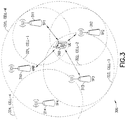
- FIG. 3 depicts an exemplary CoMP system 300 within which the examples may be implemented.
- the system 300 includes at least one UE 302 and at least one eNB 310 (e.g., a serving eNB for the UE 302).
- the eNB 310 defines a macro cell (cell-m) 320 of coverage.
- Within the macro cell 320 is at least one transmission point (TP1 311, TP2 312, TP3 313, TP4 314) coupled at least to the eNB 310 and, in some examples, to one another.
- Each transmission point defines a corresponding local cell of coverage (cell-1 321, cell-2 322, cell-3 323, cell-4 324) that may be entirely within the macro cell 320 or may overlap with a portion of the macro cell 320.
- the transmission points may comprise RRHs or additional eNBs.
- the transmission points are coupled to the eNB 310 to enable at least coordinated transmission to the UE 302.
- the one or more (at least one) local cells of coverage may also be referred to as hotspots, hotspot cells or local hotspots, as non-limiting examples.
- the eNB 310 may be coupled to the at least one transmission point via at least one data and control path, which may be implemented as an X2 interface for the case of another logical base station or may be a direct eNB internal interface (e.g., an optical fiber connection) for connection to another type of transmission point such as at least one RRH, as non-limiting examples.
- the eNB 310 covers a single macro cell (cell-m 320) via one or more antennas.
- the UE 302 is attached to the eNB 310 and communicates with the eNB 310 at least for UL control (PUCCH), uplink data (PUSCH), and DL control (PDCCH) channels.
- the UE 302 can receive a joint transmission (e.g., on a PDSCH) from any subset of eNB 310, TP1 311, TP2 312, TP3 313, and TP4 314.
- a transmission point is defined as a co-located set of antennas.
- the transmission points may or may not be assigned a same cell-id.
- the transmission points may or may not belong to a same eNB (e.g., RRHs for eNB 310, a same serving eNB).
- typically CoMP clusters are defined geographically to prevent and/or minimize overlap of macro cells or overlap of CoMP clusters, for example.
- each transmission point may include a controller, such as at least one data processor, at least one computer-readable memory medium (e.g., embodied as a memory) that stores a program of computer instructions, at least one suitable transmitter and at least one suitable receiver (e.g., at least one RF transceiver) operable for communication with the UE 302 via one or more antennas (typically several when MIMO operation is in use).
- the transmission points may be under complete control of a single eNB, although dispersed control is also possible.
- the transmission points and the macro eNB may be centrally controlled together. While the control is typically at the location of the macro eNB, in other examples it may be at a location that is connected to the eNB and/or the transmission points.
- the UE may communicate with one or more transmission points, one or more transmission nodes, the eNB and/or any suitable combination thereof.
- any of these devices and/or logical entities may implement the examples as discussed herein. It should be appreciated that the examples described herein may be implemented for traditional macro-cell CoMP operation as well as operations having distributed antennas within a cell (e.g., enabled by RRHs).
- a UE-specific DMRS may be signaled to the UE 302, for example, by the eNB 310.
- the UE-specific DMRS may be signaled in every UL grant.
- there also may be semi-persistent grants that have a longer valid time e.g., the UE-specific DMRS sequence may persist for more than one UL grant and/or it may not be signaled in every UL grant).
- Examples utilize new arrangements for UL DMRS. Instead of using full length cyclically extended ZC sequences for allocated PRBs, examples suggest that a number of new sequences be defined for CoMP DMRS purposes with a length of the sequences being equal to or exceeding the system bandwidth (a total number of frequency pins). As non-limiting examples, these new sequences may comprise ZC sequences, extended ZC sequences, truncated ZC sequences and/or computer-searched sequences. One of these new sequences is allocated to a specific CoMP cluster at a time (e.g., each CoMP cluster), being a base sequence for the cluster.
- a group of orthogonal sequences for the cluster is then obtained by applying a number of (e.g., up to 12) cyclic shifts to the base sequence.
- a CoMP UE in the CoMP cluster is assigned one of the orthogonal sequences in the CoMP cluster and derives its own DMRS sequence by taking a portion of the assigned sequence (e.g., a portion of the full length cyclically shifted version of the base sequence), for example, according to its PUSCH PRB allocation.
- the UE-specific DMRS in CoMP mode depends on the actual frequency location of the PUSCH PRB allocation of the UE, but is independent (as for each PRB) on the total number of PRBs allocated for the UE in a given subframe.
- CoMP UEs with overlapping PRB allocations are assigned to different CS values, thus ensuring that CoMP UEs within a CoMP cluster have orthogonal DMRS sequences irrespective of their PRB allocations.
- a set of base sequences where the length of each base sequence is greater than or equal to the total number of frequency pins in the assumed frequency carrier, is defined such that the full sequences, as well as their arbitrary subsequences, fulfill desired characteristics of the UL DMRS.
- the desired characteristics may include one or more of the following: (i) the full sequences (e.g., the set of base sequences in use) and all of the arbitrary sequences (e.g., the cyclically-shifted base sequences) have a low peak to average ratio or CM; (ii) there is a low cross-correlation value between the full sequences and the arbitrary sequences; and/or (iii) there is a low cross-correlation value between sequences used in earlier releases (e.g., legacy sequences) and the full sequences and their arbitrary sequences.
- a limited subset of sequences is selected from a full set of available sequences of a given length, for example, by minimizing the maximum CM or average CM over the possible PRB allocations.
- One of these base sequences is assigned to each CoMP cluster, serving as a base sequence for that CoMP cluster.
- a CoMP cluster-specific set of full length (DMRS) sequences are obtained by applying different CSs to the base sequence.
- Each CoMP UE is assigned to one of the cluster-specific full length (DMRS) sequences and assumes a portion of that sequence according to its PUSCH PRB allocation as a UE-specific DMRS sequence.
- the actual UE-specific DMRS sequence depends only on the frequency location of its PUSCH PRB allocation and a CS value assigned to the UE.
- different UEs can have overlapping PUSCH PRB assignments. As non-limiting example, this may occur when different UEs are allocated in different cells. As a further non-limiting example, this may also occur among UEs belonging to a same cell in the case of MU-MIMO.
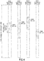
- FIG. 4 shows an example of how four UEs (UE1-UE4) with partially overlapping PRB allocations may obtain their respective UE-specific DMRS sequences.
- each UE is assigned a different CS of the base sequence for the CoMP cluster.
- the UE-specific DMRS is obtained based on each UE's PRB assignment (e.g., for the PUSCH). Since each CS of the base sequence is orthogonal, even though the UE PRB assignments overlap, the individual UE-specific DMRS sequences are orthogonal to one another.
- a UE is assigned to the CoPM cluster-specific DMRS sequence (which is either the cluster-specific base sequence or a cyclically-shifted version) that is represented numerically by the sequence ⁇ 1,2,3,...,1024 ⁇ .
- the PRB PUSCH allocation for that UE is for frequency pins ⁇ 25,26,27,...,48 ⁇ .
- the UE-specific DMRS sequence is thus represented simply by the sequence ⁇ 25,26,27,...,48 ⁇ .
- CoMP cluster-specific base sequences may be semi-statically set or they may be subject to either slot-based or subframe-based hopping.
- Time-domain OCC may be used to further improve orthogonality between UEs in the CoMP mode or to enable orthogonality between CoMP UEs and legacy UEs.
- one or more parameters pertaining to the base sequence may be signaled to UEs semi-statically while CS and/or OCC parameters may be signaled dynamically via a DCI channel.
- a UE capable of CoMP features may be assigned to the CoMP mode semi-statically or dynamically.
- the above-described examples provide a number of advantages over the prior art. First, they provide for orthogonal DMRS sequences within the CoMP cluster with high scheduling flexibility. The sequences are simple to configure, essentially not requiring any increase in control signaling overhead. Moreover, the examples provide for good cross-correlation properties between DMRS sequences of CoMP UEs and legacy UEs.
- a DL channel allocation may be used.
- a PDCCH allocation may be used.
- a PDSCH allocation may be used.
- the base sequences are known by the base station and/or the mobile device (e.g., UE) a priori (e.g., in advance, in advance such that the entire base sequence does not need to be signaled).
- a priori e.g., in advance, in advance such that the entire base sequence does not need to be signaled.
- they may be specified in one or more standards and/or form a part of the communication protocol(s) in use.
- an indication of the base sequence e.g., at least one identifier, at least one identification, at least one label, at least one index
- the cyclic shifts are known by the base station and/or the mobile device (e.g., UE) a priori (e.g., in advance, in advance such that the entire cyclic shift (e.g., entirety of the information) does not need to be signaled).
- a priori e.g., in advance, in advance such that the entire cyclic shift (e.g., entirety of the information) does not need to be signaled).
- they may be specified in one or more standards and/or form a part of the communication protocol(s) in use.
- an indication of the cyclic shift e.g., at least one identifier, at least one identification, at least one label, at least one index
- the indication of a base sequence may comprise at least a portion of the base sequence and/or an entirety of the base sequence.
- the indication of a cyclic shift may comprise at least a portion of the cyclic shift (e.g., the cyclic shift value) and/or an entirety of the cyclic shift.
- reception points e.g., transmission points and/or the serving eNB that are receiving signals/communication from a given UE
- the reception point(s) may calculate the UE-specific DMRS sequence and/or may be informed of the UE-specific DMRS sequence (e.g., via a communication from the UE, via a communication from the serving eNB), as non-limiting examples.
- the indication of a base sequence and the indication of a cyclic shift may be transmitted/received using one message and/or one communication. In further examples, the indication of a base sequence and the indication of a cyclic shift may be transmitted/received using at least two separate messages and/or at least two separate communications.
- an applied cyclic shift may be defined as a combination of one or more of: a UE-specific value (e.g., indicated by UL grant or configuration of a semi-persistent allocation), a cell-specific offset (e.g., provided in or with system information), and/or a pseudorandom value determined using at least one of the cell ID (e.g., given by PSS and/or SSS), the frame number and/or the slot number.
- three messages may be used (e.g., grant, system info and synchronization channels).
- the examples may be implemented as a computer program product comprising program instructions embodied on a tangible computer-readable medium. Execution of the program instructions results in operations comprising steps of utilizing the example or steps of the method.
- a program storage device e.g., a computer-readable medium, a memory
- a machine e.g., a computer, a mobile station, a mobile device, a mobile node
- a program of instructions e.g., a program, a computer program
- the operations comprise steps of utilizing the example or steps of the method.
- the various blocks shown in Figures 5 and 6 may be viewed as method steps, as operations that result from operation of computer program code and/or as one or more coupled components (e.g., function blocks, circuits, integrated circuits, logic circuit elements) constructed to carry out the associated function(s).
- the blocks may also be considered to correspond to one or more functions and/or operations that are performed by one or more components, apparatus, processors, computer programs, circuits, integrated circuits, application-specific integrated circuits (ASICs), chips and/or function blocks. Any and/or all of the above may be implemented in any practicable arrangement or solution that enables operation in accordance with the examples.
- the arrangement of the blocks shown in Figures 5 and 6 should be considered merely exemplary and non-limiting. It should be appreciated that the blocks may correspond to one or more functions and/or operations that may be performed in any order (e.g., any practicable, suitable and/or feasible order) and/or concurrently (e.g., as practicable, suitable and/or feasible) so as to implement one or more of the examples. In addition, one or more additional steps, functions and/or operations may be utilized in conjunction with those illustrated in Figures 5 and 6 so as to implement one or more further examples, such as those described in further detail herein.
- connection means any connection or coupling, either direct or indirect, between two or more elements, and may encompass the presence of one or more intermediate elements between two elements that are “connected” or “coupled” together.
- the coupling or connection between the elements can be physical, logical, or a combination thereof.
- two elements may be considered to be “connected” or “coupled” together by the use of one or more wires, cables and/or printed electrical connections, as well as by the use of electromagnetic energy, such as electromagnetic energy having wavelengths in the radio frequency region, the microwave region and the optical region (both visible and invisible), as several non-limiting and non-exhaustive examples.
- mobile device-specific means that the identified item is unique to that mobile device (e.g., among other such mobile devices) at least for a given region of the system (e.g., within the particular macro cell or within the particular CoMP cluster).
- the various examples may be implemented in hardware or special purpose circuits, software, logic or any combination thereof.
- some aspects may be implemented in hardware, while other aspects may be implemented in firmware or software which may be executed by a controller, microprocessor or other computing device, although the invention is not limited thereto.
- firmware or software which may be executed by a controller, microprocessor or other computing device, although the invention is not limited thereto. While various aspects of the examples may be illustrated and described as block diagrams, flow charts, or using some other pictorial representation, it is well understood that these blocks, apparatus, systems, techniques or methods described herein may be implemented in, as nonlimiting examples, hardware, software, firmware, special purpose circuits or logic, general purpose hardware or controller or other computing devices, or some combination thereof.
- the integrated circuit, or circuits may comprise circuitry (as well as possibly firmware) for embodying at least one or more of a data processor or data processors, a digital signal processor or processors, baseband circuitry and radio frequency circuitry that are configurable so as to operate in accordance with the examples.
- the examples may be practiced in various components such as integrated circuit modules.
- the design of integrated circuits is by and large a highly automated process. Complex and powerful software tools are available for converting a logic level design into a semiconductor circuit design ready to be etched and formed on a semiconductor substrate.
- the examples may be practiced in various components such as integrated circuit chips and modules. It should thus be appreciated that the examples may be realized in an apparatus that is embodied as an integrated circuit, where the integrated circuit may comprise circuitry (as well as possibly firmware) for embodying at least one or more of a data processor, a digital signal processor, baseband circuitry and radio frequency circuitry that are configurable so as to operate in accordance with the examples.
- the integrated circuit may comprise circuitry (as well as possibly firmware) for embodying at least one or more of a data processor, a digital signal processor, baseband circuitry and radio frequency circuitry that are configurable so as to operate in accordance with the examples.
- Programs such as those provided by Synopsys, Inc. of Mountain View, California and Cadence Design, of San Jose, California automatically route conductors and locate components on a semiconductor chip using well established rules of design as well as libraries of pre-stored design modules.
- the resultant design in a standardized electronic format (e.g., Opus, GDSII, or the like) may be transmitted to a semiconductor fabrication facility or "fab" for fabrication.
Claims (14)
- Procédé, qui comprend :la réception (501), par un dispositif mobile, d'une indication d'une séquence de base et d'une indication d'un décalage circulaire depuis une station de base ;l'obtention (502), par le dispositif mobile, d'une séquence de signaux de référence de démodulation spécifique à un dispositif mobile, en :calculant une séquence spécifique à un dispositif mobile en appliquant le décalage circulaire indiqué par l'indication reçue d'un décalage circulaire à la séquence de base indiquée par l'indication reçue d'une séquence de base ; etsélectionnant une partie de la séquence spécifique à un dispositif mobile calculée pour utiliser en tant que séquence de signaux de référence de démodulation spécifique à un dispositif mobile en fonction d'une attribution de bloc de ressources physiques spécifique à un dispositif mobile.
- Procédé selon la revendication 1, dans lequel la séquence de base indiquée comprend au moins l'une parmi : une séquence de Zadoff-Chu, une séquence de Zadoff-Chu étendue, une séquence de Zadoff-Chu tronquée ou une séquence recherchée par un ordinateur.
- Procédé selon l'une quelconque des revendications 1-2, dans lequel une valeur de décalage circulaire pour le décalage circulaire indiqué par l'indication reçue d'un décalage circulaire est calculée en tant que : c = n (b/12), où c est la valeur de décalage circulaire, où b est une longueur de la séquence de base indiquée par l'indication reçue d'une séquence de base, et où n est un nombre entier tel que 0 ≤ n ≤ 11 tel que déterminé par l'indication reçue d'un décalage circulaire.
- Procédé selon l'une quelconque des revendications 1-3, dans lequel la séquence de base indiquée présente une longueur supérieure ou égale à un nombre total de broches de fréquence pour une bande passante de système.
- Procédé selon l'une quelconque des revendications 1-4, dans lequel l'attribution de bloc de ressources physiques spécifique à un dispositif mobile est pour un canal physique partagé en liaison montante.
- Procédé selon l'une quelconque des revendications 1-5, qui comprend en outre : la transmission, par le dispositif mobile, d'un signal de référence de démodulation à l'aide de la séquence de signaux de référence de démodulation spécifique à un dispositif mobile.
- Procédé selon l'une quelconque des revendications 1-6, dans lequel le décalage circulaire comprend l'un d'une pluralité de décalages circulaires, dans lequel chaque décalage circulaire de la séquence de base de la pluralité de décalages circulaires est orthogonal aux autres décalages circulaires de la séquence de base.
- Appareil qui comprend :des moyens pour recevoir (501) une indication d'une séquence de base et une indication d'un décalage circulaire depuis une station de base ;des moyens pour obtenir (502) une séquence de signaux de référence de démodulation spécifique à un dispositif mobile, en :calculant une séquence spécifique à un dispositif mobile en appliquant le décalage circulaire indiqué par l'indication reçue d'un décalage circulaire à la séquence de base indiquée par l'indication reçue d'une séquence de base ; etsélectionnant une partie de la séquence spécifique à un dispositif mobile calculée pour utiliser en tant que séquence de signaux de référence de démodulation spécifique à un dispositif mobile en fonction d'une attribution de bloc de ressources physiques spécifique à un dispositif mobile.
- Procédé, qui comprend :l'assignation (601), par une station de base, d'un décalage circulaire à un dispositif mobile ;la transmission (602), depuis la station de base vers le dispositif mobile, d'une indication d'une séquence de base et d'une indication du décalage circulaire assigné ; et
la réception, par la station de base, d'un signal de référence de démodulation à l'aide d'une séquence de signaux de référence de démodulation spécifique à un dispositif mobile depuis le dispositif mobile, dans lequel la séquence de signaux de référence de démodulation spécifique à un dispositif mobile est une partie d'une séquence spécifique à un dispositif mobile qui est fonction du décalage circulaire et dans lequel la partie est fonction d'une attribution de bloc de ressources physiques spécifique à un dispositif mobile. - Procédé selon la revendication 9, dans lequel la séquence de base indiquée présente une longueur supérieure ou égale à un nombre total de broches de fréquence pour une bande passante de système.
- Procédé selon l'une quelconque des revendications 9-10, qui comprend en outre : la réception, par la station de base, de l'indication de la séquence de base depuis le réseau.
- Procédé selon l'une quelconque des revendications 9-11, dans lequel une valeur de décalage circulaire pour le décalage circulaire indiqué par l'indication d'un décalage circulaire est calculée en tant que : c = n (b/12), où c est la valeur de décalage circulaire, où b est une longueur de la séquence de base indiquée par l'indication d'une séquence de base, et où n est un nombre entier tel que 0 ≤ n ≤ 11 tel que déterminé par l'indication d'un décalage circulaire.
- Procédé selon l'une quelconque des revendications 9-12, dans lequel la partie sélectionnée de la séquence spécifique à un dispositif mobile calculée correspond à une attribution de bloc de ressources physiques spécifique à un dispositif mobile.
- Appareil qui comprend :des moyens pour assigner (601) un décalage circulaire à un dispositif mobile ;des moyens pour transmettre (602), vers le dispositif mobile, une indication d'une séquence de base et une indication du décalage circulaire assigné ; etdes moyens pour recevoir un signal de référence de démodulation à l'aide d'une séquence de signaux de référence de démodulation spécifique à un dispositif mobile depuis le dispositif mobile, dans lequel la séquence de signaux de référence de démodulation spécifique à un dispositif mobile est une partie d'une séquence spécifique à un dispositif mobile qui est fonction du décalage circulaire et dans lequel la partie est fonction d'une attribution de bloc de ressources physiques spécifique à un dispositif mobile.
Applications Claiming Priority (2)
| Application Number | Priority Date | Filing Date | Title |
|---|---|---|---|
| US13/289,118 US20130114514A1 (en) | 2011-11-04 | 2011-11-04 | DMRS Arrangements For Coordinated Multi-Point Communication |
| PCT/FI2012/050930 WO2013064721A1 (fr) | 2011-11-04 | 2012-09-27 | Configurations de dmrs pour la communication multipoint coordonnée |
Publications (3)
| Publication Number | Publication Date |
|---|---|
| EP2774438A1 EP2774438A1 (fr) | 2014-09-10 |
| EP2774438A4 EP2774438A4 (fr) | 2015-07-22 |
| EP2774438B1 true EP2774438B1 (fr) | 2020-11-04 |
Family
ID=48191424
Family Applications (1)
| Application Number | Title | Priority Date | Filing Date |
|---|---|---|---|
| EP12846276.9A Active EP2774438B1 (fr) | 2011-11-04 | 2012-09-27 | Configurations de dmrs pour la communication multipoint coordonnée |
Country Status (6)
| Country | Link |
|---|---|
| US (1) | US20130114514A1 (fr) |
| EP (1) | EP2774438B1 (fr) |
| CN (1) | CN104054384A (fr) |
| DK (1) | DK2774438T3 (fr) |
| PT (1) | PT2774438T (fr) |
| WO (1) | WO2013064721A1 (fr) |
Families Citing this family (20)
| Publication number | Priority date | Publication date | Assignee | Title |
|---|---|---|---|---|
| KR101699493B1 (ko) * | 2010-05-03 | 2017-01-26 | 주식회사 팬택 | Mimo 환경에서 직교성을 제공하는 사이클릭 쉬프트 파라메터를 송수신하는 방법 및 장치 |
| WO2013025140A1 (fr) * | 2011-08-12 | 2013-02-21 | Telefonaktiebolaget L M Ericsson (Publ) | Procédés et appareils pour gérer des signaux de référence dans un réseau cellulaire |
| JP5934723B2 (ja) * | 2012-01-27 | 2016-06-15 | パナソニック インテレクチュアル プロパティ コーポレーション オブ アメリカPanasonic Intellectual Property Corporation of America | 送信装置及び送信方法 |
| US9083479B2 (en) | 2012-05-11 | 2015-07-14 | Intel Corporation | Signaling for downlink coordinated multipoint in a wireless communication system |
| US8874103B2 (en) * | 2012-05-11 | 2014-10-28 | Intel Corporation | Determining proximity of user equipment for device-to-device communication |
| US8838119B2 (en) | 2012-06-26 | 2014-09-16 | Futurewei Technologies, Inc. | Method and system for dynamic cell configuration |
| US9521637B2 (en) | 2013-02-14 | 2016-12-13 | Blackberry Limited | Small cell demodulation reference signal and initial synchronization |
| US9924504B2 (en) * | 2013-10-07 | 2018-03-20 | Qualcomm Incorporated | Joint PDCCH/PDSCH scheduling techniques to enhance PDSCH interference cancellation |
| CN106160990B (zh) * | 2015-04-27 | 2019-06-07 | 中国移动通信集团公司 | 一种解调参考信号dmrs资源配置的方法及装置 |
| WO2017111466A1 (fr) * | 2015-12-21 | 2017-06-29 | 엘지전자 주식회사 | Procédé et appareil destinés à la génération et à la transmission de signal de référence et de données dans un système de communication sans fil |
| CN108834432B (zh) * | 2016-04-15 | 2021-02-09 | 华为技术有限公司 | 上行数据发送接收方法、用户设备和接入网设备 |
| CN107623563A (zh) * | 2016-07-11 | 2018-01-23 | 北京信威通信技术股份有限公司 | 一种v2x通信中的配置dmrs的方法及装置 |
| CN108289021B (zh) * | 2017-01-09 | 2021-10-01 | 华为技术有限公司 | 参考信号的传输方法和设备 |
| WO2018127137A1 (fr) * | 2017-01-09 | 2018-07-12 | 华为技术有限公司 | Procédé et appareil de transmission de signal de référence |
| CN108833070B (zh) * | 2017-09-08 | 2020-01-03 | 华为技术有限公司 | 基于序列的信号处理方法及装置 |
| CN112511285B (zh) | 2017-09-08 | 2021-11-19 | 华为技术有限公司 | 基于序列的信号处理方法及装置 |
| US10924245B2 (en) * | 2017-12-06 | 2021-02-16 | Qualcomm Incorporated | DMRS design for SPS assigned traffic |
| US11678336B2 (en) * | 2019-03-29 | 2023-06-13 | Qualcomm Incorporated | Indication design and signaling |
| CN115396070B (zh) * | 2021-05-19 | 2024-01-30 | 大唐联仪科技有限公司 | 信号同步方法、装置及存储介质 |
| WO2023164819A1 (fr) * | 2022-03-02 | 2023-09-07 | Huawei Technologies Co.,Ltd. | Signaux de référence en forme d'impulsions et à chevauchement |
Citations (2)
| Publication number | Priority date | Publication date | Assignee | Title |
|---|---|---|---|---|
| US20080298433A1 (en) * | 2007-04-30 | 2008-12-04 | Nokia Siemens Networks Oy | Coordinated cyclic shift and sequence hopping for Zadoff-Chu, modified Zadoff-Chu, and block-wise spreading sequences |
| US20110176502A1 (en) * | 2008-07-22 | 2011-07-21 | Lg Electronics Inc. | Method for allocating phich and generating reference signal in system using single-user mimo based on multiple codewords when transmitting uplink |
Family Cites Families (22)
| Publication number | Priority date | Publication date | Assignee | Title |
|---|---|---|---|---|
| EP2124471A4 (fr) * | 2007-03-01 | 2014-07-23 | Ntt Docomo Inc | Dispositif de station de base et procédé de commande de communication |
| US20090046645A1 (en) * | 2007-08-13 | 2009-02-19 | Pierre Bertrand | Uplink Reference Signal Sequence Assignments in Wireless Networks |
| US9065646B2 (en) * | 2008-02-04 | 2015-06-23 | Nokia Solutions And Networks Oy | ACK/NACK channelization for resource blocks containing both ACK/NACK and CQI |
| US8848581B2 (en) * | 2008-06-27 | 2014-09-30 | Nokia Corporation | Unsynchronized signaling in radio systems using frequency domain processing |
| KR20100019947A (ko) * | 2008-08-11 | 2010-02-19 | 엘지전자 주식회사 | 무선 통신 시스템에서 정보 전송 방법 |
| CN101651890A (zh) * | 2008-08-11 | 2010-02-17 | 夏普株式会社 | 反馈上行控制信令的方法、基站、用户设备及通信系统 |
| KR101571566B1 (ko) * | 2008-08-11 | 2015-11-25 | 엘지전자 주식회사 | 무선 통신 시스템에서 제어신호 전송 방법 |
| US20100067512A1 (en) * | 2008-09-17 | 2010-03-18 | Samsung Electronics Co., Ltd. | Uplink transmit diversity schemes with 4 antenna ports |
| CN102246446B (zh) * | 2008-11-14 | 2014-10-29 | Lg电子株式会社 | 用于在无线通信系统中发送信号的方法和装置 |
| KR101639810B1 (ko) * | 2009-01-13 | 2016-07-25 | 엘지전자 주식회사 | 무선통신 시스템에서 사운딩 참조신호의 전송방법 |
| WO2010124716A1 (fr) | 2009-04-27 | 2010-11-04 | Nokia Siemens Networks Oy | Signaux de référence de démodulation dans un système de communication |
| WO2010140859A2 (fr) * | 2009-06-03 | 2010-12-09 | 엘지전자 주식회사 | Procédé et appareil pour émettre un signal de référence de sondage |
| EP2452535A1 (fr) * | 2009-07-07 | 2012-05-16 | Telefonaktiebolaget LM Ericsson (publ) | Procédure d accès aléatoire faisant appel à un décalage circulaire du signal de référence de démodulation |
| CN101989871B (zh) * | 2009-07-30 | 2014-06-04 | 电信科学技术研究院 | 一种探测参考信号的发送方法、装置和系统 |
| KR20110014101A (ko) * | 2009-08-04 | 2011-02-10 | 엘지전자 주식회사 | 릴레이 백홀 자원 할당 |
| US8634362B2 (en) * | 2009-10-01 | 2014-01-21 | Qualcomm Incorporated | Reference signals for multi-user MIMO communication |
| CA2786472C (fr) * | 2010-01-08 | 2016-12-20 | Interdigital Patent Holdings, Inc. | Procede et appareil permettant un mappage de ressources de canal dans une agregation de porteuses |
| CN102202409A (zh) * | 2010-03-26 | 2011-09-28 | 北京三星通信技术研究有限公司 | 一种参考符号的确定方法 |
| KR101769376B1 (ko) * | 2010-03-29 | 2017-08-30 | 엘지전자 주식회사 | 상향링크 다중 안테나 전송을 지원하기 위한 효율적인 제어정보 전송 방법 및 장치 |
| KR20110112005A (ko) * | 2010-04-05 | 2011-10-12 | 주식회사 팬택 | 직교성을 제공하는 사이클릭 쉬프트 파라메터를 송수신하는 방법 및 장치 |
| WO2012044764A2 (fr) * | 2010-10-01 | 2012-04-05 | Research In Motion Limited | Transmission en diversité avec sélection de ressources orthogonales et affectation de ressources |
| US8842628B2 (en) * | 2011-09-12 | 2014-09-23 | Blackberry Limited | Enhanced PDCCH with transmit diversity in LTE systems |
-
2011
- 2011-11-04 US US13/289,118 patent/US20130114514A1/en not_active Abandoned
-
2012
- 2012-09-27 WO PCT/FI2012/050930 patent/WO2013064721A1/fr active Application Filing
- 2012-09-27 EP EP12846276.9A patent/EP2774438B1/fr active Active
- 2012-09-27 DK DK12846276.9T patent/DK2774438T3/da active
- 2012-09-27 PT PT128462769T patent/PT2774438T/pt unknown
- 2012-09-27 CN CN201280053964.1A patent/CN104054384A/zh active Pending
Patent Citations (2)
| Publication number | Priority date | Publication date | Assignee | Title |
|---|---|---|---|---|
| US20080298433A1 (en) * | 2007-04-30 | 2008-12-04 | Nokia Siemens Networks Oy | Coordinated cyclic shift and sequence hopping for Zadoff-Chu, modified Zadoff-Chu, and block-wise spreading sequences |
| US20110176502A1 (en) * | 2008-07-22 | 2011-07-21 | Lg Electronics Inc. | Method for allocating phich and generating reference signal in system using single-user mimo based on multiple codewords when transmitting uplink |
Also Published As
| Publication number | Publication date |
|---|---|
| EP2774438A1 (fr) | 2014-09-10 |
| WO2013064721A1 (fr) | 2013-05-10 |
| DK2774438T3 (da) | 2020-12-07 |
| US20130114514A1 (en) | 2013-05-09 |
| EP2774438A4 (fr) | 2015-07-22 |
| WO2013064721A8 (fr) | 2014-04-17 |
| PT2774438T (pt) | 2020-11-26 |
| CN104054384A (zh) | 2014-09-17 |
Similar Documents
| Publication | Publication Date | Title |
|---|---|---|
| EP2774438B1 (fr) | Configurations de dmrs pour la communication multipoint coordonnée | |
| US8681727B2 (en) | Flexible radio channel sounding | |
| EP3949227B1 (fr) | Procédé de différenciation de multiples programmes de transmission de canal physique partagé de liaison descendante (pdsch) | |
| US20220224480A1 (en) | Resource indication method, terminal device, and network device | |
| US10749657B2 (en) | Mapping reference signal for multi-cell transmission | |
| US10218424B2 (en) | Reference signal indications for massive MIMO networks | |
| EP2484046B1 (fr) | Appareil et procédé d'initialisation d'embrouillage de signal de référence | |
| US10250364B2 (en) | Channel measurements supporting coordinated multi-point operation | |
| US8923207B2 (en) | Method for initializing sequence of reference signal and base station using the same | |
| JP6076044B2 (ja) | 無線通信方法、無線通信システム、無線基地局及びユーザ端末 | |
| US10448379B2 (en) | Enhanced downlink control channel configuration for LTE | |
| US20130128821A1 (en) | Demodulation Reference Signal Arrangement For Uplink Coordinated Multi-Point Reception | |
| WO2013048192A1 (fr) | Appareil et procédé destinés à établir une pluralité de configurations de signal de référence dans un système de communication sans fil | |
| JP2023014231A (ja) | ユーザ装置、無線通信方法、無線基地局及び無線通信システム | |
| US20200084732A1 (en) | Reference Signal Sending and Receiving Method, Network Device, and Terminal Device | |
| US9369898B2 (en) | Method and device for measuring interference in a wireless communication system | |
| US10911122B2 (en) | Reference signal sending method, reference signal receiving method, network device, and terminal device | |
| WO2013051839A2 (fr) | Procédé et appareil pour mesurer une interférence dans un système de communication sans fil | |
| WO2020088462A1 (fr) | Procédé et appareil pour la génération d'une séquence de signal de référence de démodulation |
Legal Events
| Date | Code | Title | Description |
|---|---|---|---|
| PUAI | Public reference made under article 153(3) epc to a published international application that has entered the european phase |
Free format text: ORIGINAL CODE: 0009012 |
|
| 17P | Request for examination filed |
Effective date: 20140408 |
|
| AK | Designated contracting states |
Kind code of ref document: A1 Designated state(s): AL AT BE BG CH CY CZ DE DK EE ES FI FR GB GR HR HU IE IS IT LI LT LU LV MC MK MT NL NO PL PT RO RS SE SI SK SM TR |
|
| DAX | Request for extension of the european patent (deleted) | ||
| RA4 | Supplementary search report drawn up and despatched (corrected) |
Effective date: 20150619 |
|
| RIC1 | Information provided on ipc code assigned before grant |
Ipc: H04L 5/00 20060101AFI20150615BHEP Ipc: H04L 27/26 20060101ALI20150615BHEP |
|
| RAP1 | Party data changed (applicant data changed or rights of an application transferred) |
Owner name: NOKIA TECHNOLOGIES OY |
|
| STAA | Information on the status of an ep patent application or granted ep patent |
Free format text: STATUS: EXAMINATION IS IN PROGRESS |
|
| 17Q | First examination report despatched |
Effective date: 20181107 |
|
| RAP1 | Party data changed (applicant data changed or rights of an application transferred) |
Owner name: NOKIA TECHNOLOGIES OY |
|
| GRAP | Despatch of communication of intention to grant a patent |
Free format text: ORIGINAL CODE: EPIDOSNIGR1 |
|
| STAA | Information on the status of an ep patent application or granted ep patent |
Free format text: STATUS: GRANT OF PATENT IS INTENDED |
|
| INTG | Intention to grant announced |
Effective date: 20200618 |
|
| GRAJ | Information related to disapproval of communication of intention to grant by the applicant or resumption of examination proceedings by the epo deleted |
Free format text: ORIGINAL CODE: EPIDOSDIGR1 |
|
| STAA | Information on the status of an ep patent application or granted ep patent |
Free format text: STATUS: EXAMINATION IS IN PROGRESS |
|
| GRAR | Information related to intention to grant a patent recorded |
Free format text: ORIGINAL CODE: EPIDOSNIGR71 |
|
| GRAS | Grant fee paid |
Free format text: ORIGINAL CODE: EPIDOSNIGR3 |
|
| STAA | Information on the status of an ep patent application or granted ep patent |
Free format text: STATUS: GRANT OF PATENT IS INTENDED |
|
| INTC | Intention to grant announced (deleted) | ||
| GRAA | (expected) grant |
Free format text: ORIGINAL CODE: 0009210 |
|
| STAA | Information on the status of an ep patent application or granted ep patent |
Free format text: STATUS: THE PATENT HAS BEEN GRANTED |
|
| AK | Designated contracting states |
Kind code of ref document: B1 Designated state(s): AL AT BE BG CH CY CZ DE DK EE ES FI FR GB GR HR HU IE IS IT LI LT LU LV MC MK MT NL NO PL PT RO RS SE SI SK SM TR |
|
| INTG | Intention to grant announced |
Effective date: 20200929 |
|
| REG | Reference to a national code |
Ref country code: GB Ref legal event code: FG4D |
|
| REG | Reference to a national code |
Ref country code: CH Ref legal event code: EP |
|
| REG | Reference to a national code |
Ref country code: AT Ref legal event code: REF Ref document number: 1332199 Country of ref document: AT Kind code of ref document: T Effective date: 20201115 |
|
| REG | Reference to a national code |
Ref country code: IE Ref legal event code: FG4D |
|
| REG | Reference to a national code |
Ref country code: PT Ref legal event code: SC4A Ref document number: 2774438 Country of ref document: PT Date of ref document: 20201126 Kind code of ref document: T Free format text: AVAILABILITY OF NATIONAL TRANSLATION Effective date: 20201120 Ref country code: DE Ref legal event code: R096 Ref document number: 602012073126 Country of ref document: DE |
|
| REG | Reference to a national code |
Ref country code: DK Ref legal event code: T3 Effective date: 20201203 |
|
| REG | Reference to a national code |
Ref country code: NL Ref legal event code: MP Effective date: 20201104 |
|
| REG | Reference to a national code |
Ref country code: AT Ref legal event code: MK05 Ref document number: 1332199 Country of ref document: AT Kind code of ref document: T Effective date: 20201104 |
|
| PG25 | Lapsed in a contracting state [announced via postgrant information from national office to epo] |
Ref country code: RS Free format text: LAPSE BECAUSE OF FAILURE TO SUBMIT A TRANSLATION OF THE DESCRIPTION OR TO PAY THE FEE WITHIN THE PRESCRIBED TIME-LIMIT Effective date: 20201104 Ref country code: FI Free format text: LAPSE BECAUSE OF FAILURE TO SUBMIT A TRANSLATION OF THE DESCRIPTION OR TO PAY THE FEE WITHIN THE PRESCRIBED TIME-LIMIT Effective date: 20201104 Ref country code: NO Free format text: LAPSE BECAUSE OF FAILURE TO SUBMIT A TRANSLATION OF THE DESCRIPTION OR TO PAY THE FEE WITHIN THE PRESCRIBED TIME-LIMIT Effective date: 20210204 Ref country code: GR Free format text: LAPSE BECAUSE OF FAILURE TO SUBMIT A TRANSLATION OF THE DESCRIPTION OR TO PAY THE FEE WITHIN THE PRESCRIBED TIME-LIMIT Effective date: 20210205 |
|
| PG25 | Lapsed in a contracting state [announced via postgrant information from national office to epo] |
Ref country code: IS Free format text: LAPSE BECAUSE OF FAILURE TO SUBMIT A TRANSLATION OF THE DESCRIPTION OR TO PAY THE FEE WITHIN THE PRESCRIBED TIME-LIMIT Effective date: 20210304 Ref country code: SE Free format text: LAPSE BECAUSE OF FAILURE TO SUBMIT A TRANSLATION OF THE DESCRIPTION OR TO PAY THE FEE WITHIN THE PRESCRIBED TIME-LIMIT Effective date: 20201104 Ref country code: LV Free format text: LAPSE BECAUSE OF FAILURE TO SUBMIT A TRANSLATION OF THE DESCRIPTION OR TO PAY THE FEE WITHIN THE PRESCRIBED TIME-LIMIT Effective date: 20201104 Ref country code: PL Free format text: LAPSE BECAUSE OF FAILURE TO SUBMIT A TRANSLATION OF THE DESCRIPTION OR TO PAY THE FEE WITHIN THE PRESCRIBED TIME-LIMIT Effective date: 20201104 Ref country code: ES Free format text: LAPSE BECAUSE OF FAILURE TO SUBMIT A TRANSLATION OF THE DESCRIPTION OR TO PAY THE FEE WITHIN THE PRESCRIBED TIME-LIMIT Effective date: 20201104 Ref country code: AT Free format text: LAPSE BECAUSE OF FAILURE TO SUBMIT A TRANSLATION OF THE DESCRIPTION OR TO PAY THE FEE WITHIN THE PRESCRIBED TIME-LIMIT Effective date: 20201104 Ref country code: BG Free format text: LAPSE BECAUSE OF FAILURE TO SUBMIT A TRANSLATION OF THE DESCRIPTION OR TO PAY THE FEE WITHIN THE PRESCRIBED TIME-LIMIT Effective date: 20210204 |
|
| REG | Reference to a national code |
Ref country code: LT Ref legal event code: MG9D |
|
| PG25 | Lapsed in a contracting state [announced via postgrant information from national office to epo] |
Ref country code: HR Free format text: LAPSE BECAUSE OF FAILURE TO SUBMIT A TRANSLATION OF THE DESCRIPTION OR TO PAY THE FEE WITHIN THE PRESCRIBED TIME-LIMIT Effective date: 20201104 |
|
| PG25 | Lapsed in a contracting state [announced via postgrant information from national office to epo] |
Ref country code: LT Free format text: LAPSE BECAUSE OF FAILURE TO SUBMIT A TRANSLATION OF THE DESCRIPTION OR TO PAY THE FEE WITHIN THE PRESCRIBED TIME-LIMIT Effective date: 20201104 Ref country code: RO Free format text: LAPSE BECAUSE OF FAILURE TO SUBMIT A TRANSLATION OF THE DESCRIPTION OR TO PAY THE FEE WITHIN THE PRESCRIBED TIME-LIMIT Effective date: 20201104 Ref country code: SK Free format text: LAPSE BECAUSE OF FAILURE TO SUBMIT A TRANSLATION OF THE DESCRIPTION OR TO PAY THE FEE WITHIN THE PRESCRIBED TIME-LIMIT Effective date: 20201104 Ref country code: SM Free format text: LAPSE BECAUSE OF FAILURE TO SUBMIT A TRANSLATION OF THE DESCRIPTION OR TO PAY THE FEE WITHIN THE PRESCRIBED TIME-LIMIT Effective date: 20201104 Ref country code: CZ Free format text: LAPSE BECAUSE OF FAILURE TO SUBMIT A TRANSLATION OF THE DESCRIPTION OR TO PAY THE FEE WITHIN THE PRESCRIBED TIME-LIMIT Effective date: 20201104 Ref country code: EE Free format text: LAPSE BECAUSE OF FAILURE TO SUBMIT A TRANSLATION OF THE DESCRIPTION OR TO PAY THE FEE WITHIN THE PRESCRIBED TIME-LIMIT Effective date: 20201104 |
|
| REG | Reference to a national code |
Ref country code: DE Ref legal event code: R097 Ref document number: 602012073126 Country of ref document: DE |
|
| PLBE | No opposition filed within time limit |
Free format text: ORIGINAL CODE: 0009261 |
|
| STAA | Information on the status of an ep patent application or granted ep patent |
Free format text: STATUS: NO OPPOSITION FILED WITHIN TIME LIMIT |
|
| 26N | No opposition filed |
Effective date: 20210805 |
|
| PG25 | Lapsed in a contracting state [announced via postgrant information from national office to epo] |
Ref country code: AL Free format text: LAPSE BECAUSE OF FAILURE TO SUBMIT A TRANSLATION OF THE DESCRIPTION OR TO PAY THE FEE WITHIN THE PRESCRIBED TIME-LIMIT Effective date: 20201104 Ref country code: IT Free format text: LAPSE BECAUSE OF FAILURE TO SUBMIT A TRANSLATION OF THE DESCRIPTION OR TO PAY THE FEE WITHIN THE PRESCRIBED TIME-LIMIT Effective date: 20201104 Ref country code: NL Free format text: LAPSE BECAUSE OF FAILURE TO SUBMIT A TRANSLATION OF THE DESCRIPTION OR TO PAY THE FEE WITHIN THE PRESCRIBED TIME-LIMIT Effective date: 20201104 |
|
| PG25 | Lapsed in a contracting state [announced via postgrant information from national office to epo] |
Ref country code: SI Free format text: LAPSE BECAUSE OF FAILURE TO SUBMIT A TRANSLATION OF THE DESCRIPTION OR TO PAY THE FEE WITHIN THE PRESCRIBED TIME-LIMIT Effective date: 20201104 |
|
| REG | Reference to a national code |
Ref country code: CH Ref legal event code: PL |
|
| REG | Reference to a national code |
Ref country code: BE Ref legal event code: MM Effective date: 20210930 |
|
| PG25 | Lapsed in a contracting state [announced via postgrant information from national office to epo] |
Ref country code: IS Free format text: LAPSE BECAUSE OF FAILURE TO SUBMIT A TRANSLATION OF THE DESCRIPTION OR TO PAY THE FEE WITHIN THE PRESCRIBED TIME-LIMIT Effective date: 20210304 Ref country code: MC Free format text: LAPSE BECAUSE OF FAILURE TO SUBMIT A TRANSLATION OF THE DESCRIPTION OR TO PAY THE FEE WITHIN THE PRESCRIBED TIME-LIMIT Effective date: 20201104 |
|
| PG25 | Lapsed in a contracting state [announced via postgrant information from national office to epo] |
Ref country code: LU Free format text: LAPSE BECAUSE OF NON-PAYMENT OF DUE FEES Effective date: 20210927 Ref country code: IE Free format text: LAPSE BECAUSE OF NON-PAYMENT OF DUE FEES Effective date: 20210927 Ref country code: BE Free format text: LAPSE BECAUSE OF NON-PAYMENT OF DUE FEES Effective date: 20210930 |
|
| PG25 | Lapsed in a contracting state [announced via postgrant information from national office to epo] |
Ref country code: LI Free format text: LAPSE BECAUSE OF NON-PAYMENT OF DUE FEES Effective date: 20210930 Ref country code: CH Free format text: LAPSE BECAUSE OF NON-PAYMENT OF DUE FEES Effective date: 20210930 |
|
| PG25 | Lapsed in a contracting state [announced via postgrant information from national office to epo] |
Ref country code: HU Free format text: LAPSE BECAUSE OF FAILURE TO SUBMIT A TRANSLATION OF THE DESCRIPTION OR TO PAY THE FEE WITHIN THE PRESCRIBED TIME-LIMIT; INVALID AB INITIO Effective date: 20120927 Ref country code: CY Free format text: LAPSE BECAUSE OF FAILURE TO SUBMIT A TRANSLATION OF THE DESCRIPTION OR TO PAY THE FEE WITHIN THE PRESCRIBED TIME-LIMIT Effective date: 20201104 |
|
| PGFP | Annual fee paid to national office [announced via postgrant information from national office to epo] |
Ref country code: GB Payment date: 20230803 Year of fee payment: 12 |
|
| PGFP | Annual fee paid to national office [announced via postgrant information from national office to epo] |
Ref country code: PT Payment date: 20230925 Year of fee payment: 12 Ref country code: FR Payment date: 20230808 Year of fee payment: 12 Ref country code: DK Payment date: 20230914 Year of fee payment: 12 Ref country code: DE Payment date: 20230802 Year of fee payment: 12 |