EP2773068A2 - Testvorrichtung und Verfahren - Google Patents
Testvorrichtung und Verfahren Download PDFInfo
- Publication number
- EP2773068A2 EP2773068A2 EP14157284.2A EP14157284A EP2773068A2 EP 2773068 A2 EP2773068 A2 EP 2773068A2 EP 14157284 A EP14157284 A EP 14157284A EP 2773068 A2 EP2773068 A2 EP 2773068A2
- Authority
- EP
- European Patent Office
- Prior art keywords
- dut
- test
- interface
- mdio
- control interface
- Prior art date
- Legal status (The legal status is an assumption and is not a legal conclusion. Google has not performed a legal analysis and makes no representation as to the accuracy of the status listed.)
- Granted
Links
Images


Classifications
-
- G—PHYSICS
- G01—MEASURING; TESTING
- G01R—MEASURING ELECTRIC VARIABLES; MEASURING MAGNETIC VARIABLES
- G01R31/00—Arrangements for testing electric properties; Arrangements for locating electric faults; Arrangements for electrical testing characterised by what is being tested not provided for elsewhere
- G01R31/28—Testing of electronic circuits, e.g. by signal tracer
- G01R31/317—Testing of digital circuits
- G01R31/31718—Logistic aspects, e.g. binning, selection, sorting of devices under test, tester/handler interaction networks, Test management software, e.g. software for test statistics or test evaluation, yield analysis
-
- H—ELECTRICITY
- H04—ELECTRIC COMMUNICATION TECHNIQUE
- H04L—TRANSMISSION OF DIGITAL INFORMATION, e.g. TELEGRAPHIC COMMUNICATION
- H04L43/00—Arrangements for monitoring or testing data switching networks
- H04L43/50—Testing arrangements
-
- G—PHYSICS
- G01—MEASURING; TESTING
- G01R—MEASURING ELECTRIC VARIABLES; MEASURING MAGNETIC VARIABLES
- G01R31/00—Arrangements for testing electric properties; Arrangements for locating electric faults; Arrangements for electrical testing characterised by what is being tested not provided for elsewhere
- G01R31/28—Testing of electronic circuits, e.g. by signal tracer
- G01R31/317—Testing of digital circuits
- G01R31/3177—Testing of logic operation, e.g. by logic analysers
-
- G—PHYSICS
- G01—MEASURING; TESTING
- G01R—MEASURING ELECTRIC VARIABLES; MEASURING MAGNETIC VARIABLES
- G01R31/00—Arrangements for testing electric properties; Arrangements for locating electric faults; Arrangements for electrical testing characterised by what is being tested not provided for elsewhere
- G01R31/28—Testing of electronic circuits, e.g. by signal tracer
- G01R31/317—Testing of digital circuits
- G01R31/3181—Functional testing
- G01R31/319—Tester hardware, i.e. output processing circuits
- G01R31/31903—Tester hardware, i.e. output processing circuits tester configuration
- G01R31/31908—Tester set-up, e.g. configuring the tester to the device under test [DUT], down loading test patterns
-
- G—PHYSICS
- G06—COMPUTING OR CALCULATING; COUNTING
- G06F—ELECTRIC DIGITAL DATA PROCESSING
- G06F11/00—Error detection; Error correction; Monitoring
- G06F11/22—Detection or location of defective computer hardware by testing during standby operation or during idle time, e.g. start-up testing
- G06F11/26—Functional testing
- G06F11/273—Tester hardware, i.e. output processing circuits
- G06F11/2733—Test interface between tester and unit under test
-
- H—ELECTRICITY
- H04—ELECTRIC COMMUNICATION TECHNIQUE
- H04B—TRANSMISSION
- H04B10/00—Transmission systems employing electromagnetic waves other than radio-waves, e.g. infrared, visible or ultraviolet light, or employing corpuscular radiation, e.g. quantum communication
- H04B10/07—Arrangements for monitoring or testing transmission systems; Arrangements for fault measurement of transmission systems
- H04B10/075—Arrangements for monitoring or testing transmission systems; Arrangements for fault measurement of transmission systems using an in-service signal
- H04B10/077—Arrangements for monitoring or testing transmission systems; Arrangements for fault measurement of transmission systems using an in-service signal using a supervisory or additional signal
- H04B10/0779—Monitoring line transmitter or line receiver equipment
-
- H—ELECTRICITY
- H04—ELECTRIC COMMUNICATION TECHNIQUE
- H04L—TRANSMISSION OF DIGITAL INFORMATION, e.g. TELEGRAPHIC COMMUNICATION
- H04L1/00—Arrangements for detecting or preventing errors in the information received
- H04L1/24—Testing correct operation
- H04L1/242—Testing correct operation by comparing a transmitted test signal with a locally generated replica
- H04L1/243—Testing correct operation by comparing a transmitted test signal with a locally generated replica at the transmitter, using a loop-back
Definitions
- the present invention relates to a test device for testing a device under test (DUT) having a control interface compliant with a standard supporting management data input/output (MDIO) and non-MDIO control signals, and more particularly, to a test device comprising an integrated control interface.
- the present invention also relates to a method of testing such a DUT by using such a test device.
- new transmission devices e.g., transceivers, transponders, and transmission modules
- data transfer rates e.g. 40 Gbps and 100 Gbps.
- new test devices are needed for validation and testing of these transmission devices.
- CFP MSA C form factor pluggable
- CFP2 CFP4 standards for hot-pluggable optical transceivers supporting data transfer rates of 40 Gbps and 100 Gbps.
- Documents relating to the CFP MSA include the "CFP MSA Hardware Specification”, Revision 1.4, June 7, 2010, the "CFP MSA CFP2 Hardware Specification”, Revision 1.0, July 31, 2013, and the "CFP MSA Management Interface Specification", Version 2.0 r09, April 10, 2012, and Version 2.2 r06a, July 31, 2013.
- the Optical Internetworking Forum (OIF) MSA for a 100 Gbps long-haul (100GLH) transmission module defines an OIF-MSA-100GLH standard for board-mounted optical transmission modules supporting a data transfer rate of 100 Gbps.
- Documents relating to the OIF-MSA-100GLH include "Implementation Agreement for 100G Long-Haul DWDM Transmission Module - Electromechanical (MSA-100GLH)", Revision 1.1, September 20, 2011.
- CFP, CFP2, CFP4, and OIF-MSA-100GLH standards specify the use of the management data input/output (MDIO) interface, as defined in Clause 45 of the "IEEE Standard for Ethernet", IEEE Std 802.3-2012, December 28, 2012. These standards also specify the use of similar sets of non-MDIO control signals, i.e., direct control signals.
- MDIO management data input/output
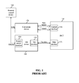
- a conventional test device 100 for testing such transmission devices does not provide direct control of a transmission device as a device under test (DUT) 150.
- the conventional test device 100 includes a test interface 110 and a remote control interface 120.
- the conventional test device 100 does not include an integrated control interface for directly controlling the DUT 150 via MDIO and non-MDIO control signals. Rather, the DUT 150 is indirectly controlled by an external control device 160.
- the remote control interface 120 of the test device 100 is coupled to the external control device 160, e.g., a computer running control software, and the test interface 110 of the test device 100 is coupled to a data interface 151 of the DUT 150.
- the external control device 160 has control over the control plane.
- the external control device 160 is coupled to a conversion device 170, which is coupled to a control interface 152 of the DUT 150.
- the conversion device 170 is required to convert control signals, e.g., universal serial bus (USB) signals, provided by the external control device 160 to MDIO and non-MDIO control signals supported by the DUT 150.
- USB universal serial bus
- one aspect of the present invention relates to a method of testing a device under test (DUT) having a control interface compliant with a standard selected from a plurality of standards each supporting a common set of management data input/output (MDIO) and non-MDIO control signals, the method comprising: coupling the DUT to a test device comprising a test interface and an integrated control interface, by coupling a data interface of the DUT to the test interface of the test device, and by coupling the control interface of the DUT to the integrated control interface of the test device; adapting the integrated control interface of the test device to the standard with which the control interface of the DUT complies, so that the integrated control interface of the test device directly and fully controls the DUT via at least the common set of MDIO and non-MDIO control signals; performing a test on the DUT, by exchanging test data signals between the data interface of the DUT and the test interface of the test device, to obtain test results; and monitoring the DUT throughout the test, by exchanging control signals selected from the common set of
- test device for testing a DUT having a control interface compliant with a standard selected from a plurality of standards each supporting a common set of MDIO and non-MDIO control signals
- the test device comprising: a test interface for coupling to a data interface of the DUT; and for exchanging test data signals with the data interface of the DUT to perform a test on the DUT and thereby obtain test results; and an integrated control interface for coupling to the control interface of the DUT; for adapting to the standard with which the control interface of the DUT complies, so that the integrated control interface directly and fully controls the DUT via at least the common set of MDIO and non-MDIO control signals; and for exchanging control signals selected from the common set of MDIO and non-MDIO control signals with the control interface of the DUT to monitor the DUT throughout the test and thereby obtain status information about the DUT.
- the present invention provides a test device for testing a device under test (DUT) having a control interface compliant with a standard selected from a plurality of standards each supporting a common set of management data input/output (MDIO) and non-MDIO control signals, and a method of testing such a DUT by using such a test device.
- DUT device under test
- MDIO management data input/output
- the test device of the present invention provides direct and full control of the DUT via MDIO and non-MDIO control signals.
- this capability often eliminates the need for an external control device, e.g., a computer running control software, and avoids synchronization difficulties between the test device and such an external control device.
- this capability often eliminates the need for a conversion device, e.g., a universal serial bus (USB) to MDIO converter and/or a USB to low-voltage transistor-transistor logic (LVTTL) converter for the non-MDIO control signals.
- the test device is often capable of performing automated tests on the DUT and correlating test results with status information about the DUT.
- the test device is capable of testing different types of DUTs having different form factors, power dissipation characteristics, and application spaces.
- the DUT is often a transmission device, such as a transceiver, a transponder, or a transmission module.
- the DUT may be a CFP, CFP2, or CFP4 transceiver or transponder, or an OIF-MSA-100GLH transmission module.
- the DUT may be an integrated circuit (IC), e.g., a gearbox, a test board, a subsystem, or a complete system.
- IC integrated circuit
- the test device is capable of testing any DUT having a control interface that is compliant with a standard selected from a plurality of standards, e.g., at least 3 standards, each supporting a common set of MDIO and non-MDIO control signals, e.g., at least 6 common non-MDIO control signals.
- a standard selected from a plurality of standards, e.g., at least 3 standards, each supporting a common set of MDIO and non-MDIO control signals, e.g., at least 6 common non-MDIO control signals.
- the plurality of standards may include the CFP, CFP2, and CFP4 standards, which each support an MDIO interface and 6 common non-MDIO control signals, as explained in further detail hereafter.
- the plurality of standards includes the CFP, CFP2, CFP4, and OIF-MSA-100GLH standards, which each support a common set of MDIO and non-MDIO control signals, as explained in further detail hereafter. Accordingly, any DUT having a control interface compliant with one of these standards may be tested by using the test device.
- additional standards e.g., 400G standards, supporting the common set of MDIO and non-MDIO control signals may be developed in the future, allowing the testing of DUTs having control interfaces compliant with those standards.
- the CFP, CFP2, CFP4, and OIF-MSA-100GLH standards specify the use of similar MDIO and non-MDIO control signals.
- MDIO and non-MDIO control signals used by the standards are tabulated in FIG. 2 .
- the MDIO control signals include an MDIO serial data signal (MDIO) and an MDIO clock signal (MDC), which are supported by all of the standards.
- MDIO control signals also include MDIO physical port address signals (PRTADRx), which differ in number depending on the standard.
- PRTADRx MDIO physical port address signals
- the CFP and OIF-MSA-100GLH standards each support 5 MDIO physical port address signals, whereas the CFP2 and CFP4 standards support only 3 MDIO physical port address signals.
- the non-MDIO control signals are direct control signals, i.e., hardware control signals, including output control signals and input monitoring signals.
- the OIF-MSA-100GLH standard supports all of the non-MDIO control signals tabulated in FIG. 2 .
- the performance monitoring sync signal (PM_SYNC) is only supported by the OIF-MSA-100GLH standard and is optional for the OIF-MSA-100GLH standard. Therefore, in some embodiments, this signal may not be supported by the test device.
- the CFP and CFP2 standards support all of the non-MDIO control signals tabulated in FIG. 2 , except for the performance monitoring sync signal.
- the CFP4 standard supports all of the non-MDIO control signals tabulated in FIG.
- the CFP, CFP2, CFP4, and OIF-MSA-100GLH standards share a common set of 6 non-MDIO control signals (TX_DIS, MOD_LOPWR, MOD_RSTn, MOD_ABS, RX_LOS, and GLB_ALRMn).
- the test device supports not only the common set of MDIO and non-MDIO control signals, but most or all of the control signals required by each standard for full control of the DUT, i.e., for control and monitoring of the DUT.
- the test device supports the common set, as well as additional control signals required by some standards.
- the test device preferably, supports all of the control signals of FIG. 2 , i.e., all the control signals necessary for full control of DUTs having control interfaces compliant with the CFP, CFP2, CFP4, and OIF-MSA-100GLH standards.
- test setup including a first embodiment of the test device 300 is illustrated in FIG. 3 .
- the test device 300 includes a test interface 310 and, unlike the conventional test device 100 of FIG. 1 , an integrated control interface 330.
- the test interface 310 and the control interface 330 of the test device 300 are housed in a common housing.
- the test interface 310 and the control interface 330 may be on a common board.
- the test interface 310 and the control interface 330 are, typically, on separate connectors.
- the control signals are brought out on an exposed interface to control an external DUT 350.
- the DUT 350 is coupled to the test device 300 by coupling a data interface 351 of the DUT 350 to the test interface 310 of the test device 300, and by coupling a control interface 352 of the DUT 350 to the control interface 330 of the test device 300.
- the DUT 350 is externally connected to the test device 300, i.e., not plugged in, and is physically separate from the test device 300. This arrangement allows the DUT 350 to be placed in a test chamber, e.g., a temperature chamber, and also allows the testing of breadboard assemblies.
- the data interface 351 of the DUT 350 is externally and directly connected to the test interface 310 of the test device 300.
- the control interface 352 of the DUT 350 is externally and directly connected to the control interface 330 of the test device 300.
- control interface 330 is capable of adapting to DUTs 350 having control interfaces compliant with different standards sharing a common set of MDIO and non-MDIO control signals, e.g., the CFP, CFP2, CFP4, and OIF-MSA-100GLH standards, as described in further detail hereafter.
- control interface 330 an MDIO interface compliant with Clause 45 of IEEE Std 802.3-2012, and a direct control interface, e.g., compliant with the CFP, CFP2, CFP4, and OIF-MSA-100GLH standards, are provided.
- the test device 300 via the integrated control interface 330, provides direct and full control of the DUT 350 via at least the common set of MDIO and non-MDIO control signals. Unlike the test setup of FIG. 1 , there is no need for an external control device 160 or a conversion device 170 in the test setup of FIG. 3 .
- the integrated control interface 330 can be used in parallel with the test interface 310 or in a standalone fashion. If the control interface 330 and the test interface 310 are used in parallel for a test, the test device 300 can have full control over both the control plane and the data plane during the test.
- the test interface 310 of the test device 300 exchanges test data signals with the data interface 351 of the DUT 350. Thereby, test results are obtained.
- the control interface 330 of the test device 300 exchanges control signals selected from the common set of MDIO and non-MDIO control signals with the control interface 352 of the DUT 350 to monitor the DUT 350, as explained in further detail hereafter. Thereby, status information about the DUT 350 is obtained.
- the test interface 310 and the control interface 330 are internally synchronized, allowing correlation of the status information with the test results.
- an exemplary architecture for the test device 300 includes a common controller 440, a common timebase 441, and a graphical user interface (GUI) 442, in addition to the test interface 310 and the integrated control interface 330.
- the test device 300 is, generally, implemented as a combination of hardware, firmware, and software.
- the common controller 440 e.g., a central processing unit (CPU), runs control software stored in non-volatile memory (not shown).
- the common controller 440 manages the test interface 310 and the control interface 330, via a control bus, in accordance with user input received from the GUI 442.
- the common timebase 441 e.g., a clock or a counter, synchronizes the common controller 440, the test interface 310, and the control interface 330 by providing current time information and synchronization signals, e.g., a 100 ms tick.
- the test interface 310 includes one or more connectors 411 and a test data generator and analyzer 412.
- the one or more connectors 411 are used to externally connect the data interface 351 of the DUT 350 to the test interface 310 of the test device 300.
- the number and type of connectors 411 depend on the type of DUT 350, since the number of lanes and the bit rate per lane varies with the electrical interface, e.g., XL attachment unit interface (XLAUI), CAUI, or CAUI-4, used by the DUT 350.
- the one or more connectors 411 are configured to receive one or more cables, e.g., a plurality of microwave coaxial cables or other cables suitable for high-speed signals.
- an optical loopback may be installed to connect optical transmit and receive ports of the DUT 350, so that optical test data signals transmitted by the DUT 350 are looped back and received by the DUT 350.
- the test data generator and analyzer 412 exchanges test data signals with the data interface 351 of the DUT 350, via the one or more connectors 411.
- the test data generator and analyzer 412 generates test data signals transmitted to the data interface 351, and analyzes test data signals received from the data interface 351 to obtain test results.
- test data generator and analyzer 412 monitors the test data signals received from the DUT 350 and detects anomalies and/or errors.
- the test data generator and analyzer 412 may perform traffic tests using different types of traffic, such as unframed, physical coding sublayer (PCS), Ethernet, internet protocol (IP), or optical transport network (OTN) traffic.
- traffic tests using different types of traffic, such as unframed, physical coding sublayer (PCS), Ethernet, internet protocol (IP), or optical transport network (OTN) traffic.
- PCS physical coding sublayer
- IP internet protocol
- OTN optical transport network
- many different types of anomalies and/or errors may be detected, e.g., bit errors, bit slips, block errors, alignment marker errors, frame check sequence (FCS) errors, lost packets, misinserted packets, frame alignment signal (FAS) errors, multiframe alignment signal (MFAS) errors, and forward error correction (FEC) errors.
- FCS frame check sequence
- FAS multiframe alignment signal
- FEC forward error correction
- the test data generator and analyzer 412 time-stamps and logs any anomalies and/or errors.
- the test data generator and analyzer 412 may also measure and log transfer performance parameters.
- the test results, including any anomalies, errors, and/or transfer performance parameters, are sent to the common controller 440, stored in non-volatile memory, and displayed via the GUI 442.
- the control interface 330 includes one or more connectors 431, an MDIO interface logic block 432, a direct control interface logic block 433, i.e., an input/output (I/O) interface logic block, and a control interface controller 434.
- the control interface 330 is an exposed interface, which is capable of cable driving and receiving.
- Drivers and receivers 435, as well as an input buffer, are provided, in accordance with the MDIO and non-MDIO control signals supported by the test device 300, to improve cable driving and receiving performance.
- the one or more connectors 431 are used to externally connect the control interface 352 of the DUT 350 to the control interface 330 of the test device 300.
- the one or more connectors 431 are configured to receive one or more cables, e.g., a single ribbon-type cable or another cable suitable for low-speed signals.
- the control interface controller 434 is a dedicated controller for the control interface 330.
- the control interface controller 434 is implemented as a microcontroller, a programmable logic device, e.g., a field-programmable gate array (FPGA), or a combination thereof.
- the MDIO interface logic block 432 typically, includes a serial to parallel converter, e.g., a serializer/deserializer (SerDes), to convert the MDIO serial data signal to parallel data signals for the control interface controller 434.
- SerDes serializer/deserializer
- control interface 330 of the test device 300 is capable of adapting to the standard with which the control interface 352 of the DUT 350 complies.
- the control interface 330 of the test device 330 may be manually or automatically configured.
- a user manually inputs the type of DUT 350, i.e., the standard with which the control interface 352 of the DUT 350 complies, via the GUI 442.
- the user also, typically, inputs the MDIO speed and the MDIO port address.
- the common controller 440 receives this information from the GUI 442 and forwards the information to the control interface controller 434.
- the control interface controller 434 then configures the MDIO interface logic block 432 and the direct control interface logic block 433 in accordance with the type of DUT 350. Configuration includes setting the MDIO speed and the MDIO port address, as well as enabling/disabling drivers and receivers 435 in accordance with the type of DUT 350.
- the control interface controller 434 automatically detects the type of DUT 350, i.e., the standard with which the control interface 352 of the DUT 350 complies, the MDIO speed, and the MDIO port address.
- the control interface controller 434 continuously senses the module absent signal (MOD_ABS).
- the control interface controller 434 releases the module reset signal (MOD_RSTn) and, after a waiting period, starts trying to access the DUT 350.
- the control interface controller 434 By scanning all possible MDIO port addresses and by varying the MDIO speed, the control interface controller 434 determines the MDIO port address and the maximum MDIO speed supported, and configures the MDIO interface logic block 432. After having established MDIO connectivity, the control interface controller 434 interrogates MDIO registers in the control interface 352 of the DUT 350. By analyzing data stored in these registers, the control interface controller 434 determines the type of DUT 350. The control interface controller 434 then configures the direct control interface logic block 433 by enabling/disabling the corresponding drivers and receivers 435 in accordance with the type of DUT 350.
- control interface 330 of the test device 300 is able to directly and fully control the DUT 350.
- the control interface controller 434 exchanges MDIO and non-MDIO control signals with the control interface 352 of the DUT 350, via the MDIO interface logic block 432 or the direct control logic block 433, respectively, and the one or more connectors 431.
- the control interface 330 via the control interface controller 434, generates MDIO control signals internally.
- the control interface controller 434 generates read/write command frames for the MDIO serial data signal (MDIO), in order to read/write data from/to registers in the control interface 352 of the DUT 350.
- the control interface controller 434 also receives read response frames via the MDIO serial data signal.
- the control interface controller 434 senses/supplies the input/output direct control signals, i.e., the non-MDIO control signals.
- the control interface 330 controls the DUT 350 via output MDIO and non-MDIO control signals.
- the integrated control interface 330 may reset the DUT 350, initialize the DUT 350, and/or activate/disable the DUT 350.
- the control interface 330 also monitors the DUT 350 and, thereby, obtains status information about the DUT 350.
- the control interface controller 434 continuously senses input non-MDIO control signals to detect any anomalies in the status of the DUT 350.
- the control interface controller 434 also periodically interrogates the DUT 350 several times a second, e.g., every 100 ms, to retrieve other status information about the DUT 350, e.g., receiver lock status, optical input level, DUT temperature, and/or DUT supply voltage, via MDIO control signals.
- the control interface controller 434 time-stamps and logs the status information, including any status anomalies.
- the status information is sent to the common controller 440, stored in non-volatile memory, and displayed via the GUI 442.
- the control interface controller 434 monitors the DUT 350 throughout the test to obtain status information about the DUT 350, while the test data generator and analyzer 412 obtains test results.
- the control interface controller 434 also controls the DUT 350 throughout the test.
- the common controller 440 receives the status information from the control interface controller 434 and the test results from the test data generator and analyzer 412. By analyzing the associated timestamps, the common controller 440 correlates the status information with the test results. Exemplary correlations include the correlation of bit errors with optical input level, the correlation of bit errors with DUT temperature, and the correlation of frame errors with DUT supply voltage.
- the correlation results are stored in non-volatile memory and displayed via the GUI 442.
- a test setup including a second embodiment of the test device 500 is illustrated in FIG. 5 .
- the second embodiment of the test device 500 is similar to the first embodiment, but includes a remote control interface 520, in addition to the test interface 310 and the integrated control interface 330.
- the remote control interface 520 e.g., a standard Ethernet remote control interface, is coupled to an external control device 560, e.g., a computer running control software.
- This test setup is advantageous when the control software and GUI built-in to the test device 500 do not provide sufficient functionality.
- the remote control interface 530 would be coupled to the common controller 440, enabling the common controller 440 to receive commands from the external control device 560 and to send information and results to the external control device 560 for storage and display.
- test device of the present invention may be used to carry out a method 600 having general steps 601 to 605. Further details of the method 600 may be found in the description of the test device hereinabove.
- a DUT having a control interface compliant with a standard selected from a plurality of standards each supporting a common set of MDIO and non-MDIO control signals is coupled to the test device, by coupling a data interface of the DUT to the test interface of the test device, and by coupling the control interface of the DUT to the control interface of the test device.
- the DUT is externally connected to the test device, by separately connecting the data interface of the DUT to the test interface of the test device, and the control interface of the DUT to the control interface of the test device.
- the control interface of the test device is adapted to the standard with which the control interface of the DUT complies, so that the control interface of the test device directly controls the DUT via at least the common set of MDIO and non-MDIO control signals.
- the control interface of the test device automatically detects the standard with which the control interface of the DUT complies and adapts itself to that standard.
- the control interface of the test device is manually configured by a user according to the standard with which the control interface of the DUT complies.
- step 603 a test is performed on the DUT by exchanging test data signals between the data interface of the DUT and the test interface of the test device. Thereby, test results for the DUT are obtained.
- step 604 the DUT is monitored throughout the test by exchanging control signals selected from the common set of MDIO and non-MDIO control signals between the control interface of the DUT and the control interface of the test device.
- the test device typically, both continuously senses non-MDIO control signals and periodically interrogates the DUT via MDIO control signals. Thereby, status information about the DUT is obtained.
- the test interface of the test device and the control interface of the test device are synchronized, and the test results and status information are time-stamped according to a common timebase.
- step 605 which is optional, the status information is correlated with the test results.
- the CFP2 transponder is first coupled to an exemplary embodiment of the test device supporting control interfaces compliant with the CFP, CFP2, CFP4, and OIF-MSA-100GLH standards.
- a data interface, e.g., CAUI-4, of the transponder is connected to the test interface of the test device, e.g., via a plurality of coaxial cables, and a control interface of the transponder is connected to the control interface of the test device, e.g., via a single ribbon-type cable.
- An optical loopback is installed to connect the transmit and receive ports of the transponder.
- the control software of the test device is launched either before or after the transponder is connected. Via the control software, the test device is instructed to begin the Ethernet traffic handling test. The test could also be started after configuration and initialization is complete.
- the control interface of the test device checks for the presence of a DUT by sensing the status of the module absent signal (MOD_ABS). Then the control interface of the test device identifies the standard with which the control interface of the transponder complies, in this instance, the CFP2 standard.
- the control interface of the test device adapts itself accordingly, so that the control interface is suitably configured to directly and fully control the transponder via the MDIO and non-MDIO control signals supported by the CFP2 standard.
- the control interface of the test device resets the transponder by toggling the module reset signal (MOD_RSTn).
- the transponder is then initialized by writing data to registers in the control interface of the transponder, via the MDIO serial data signal (MDIO). Parameters such as bit rate and operation mode are configured.
- MDIO serial data signal MDIO serial data signal
- the control interface of the test device turns on the transponder's laser by toggling the transmitter disable signal (TX_DIS).
- TX_DIS transmitter disable signal
- the test interface of the test device starts to generate Ethernet traffic with user-set characteristics.
- the Ethernet traffic is generated in accordance with important traffic parameters such as bandwidth, burst size, and frame size distribution.
- the test interface sends Ethernet traffic to the data interface of the transponder and receives Ethernet traffic from the data interface of the transponder.
- the test interface of the test device monitors the Ethernet traffic received from the data interface of the transponder and detects anomalies and/or errors. Any anomalies and/or errors, e.g., frame check sequence (FCS) errors or lost frames, are time-stamped and logged.
- FCS frame check sequence
- the test interface also measures transfer performance parameters for the Ethernet traffic, e.g., packet transfer delay or packet transfer delay variation, which are also logged.
- the control interface of the test device monitors the transponder.
- the control interface continuously monitors the non-MDIO control signals received from the control interface of the transponder to detect status anomalies. Any status anomalies are time-stamped and logged.
- the control interface of the test device also periodically retrieves other status information, e.g., receiver lock status, optical input level, transponder temperature, and/or transponder supply voltage, from the control interface of the transponder via the MDIO serial data signal.
- the status information is also time-stamped and logged.
- test results and final status information are determined and sent to the common controller of the test device.
- the common controller correlates the final test results with the final status information by analyzing the associated timestamps.
- the final test results, the final status information, and the correlation results are displayed, via the GUI of the test device, and stored in non-volatile memory. Another test may be initiated or the transponder may be disconnected from the test device.
Landscapes
- Engineering & Computer Science (AREA)
- Physics & Mathematics (AREA)
- General Engineering & Computer Science (AREA)
- General Physics & Mathematics (AREA)
- Computer Networks & Wireless Communication (AREA)
- Signal Processing (AREA)
- Theoretical Computer Science (AREA)
- Electromagnetism (AREA)
- Computer Hardware Design (AREA)
- Quality & Reliability (AREA)
- Tests Of Electronic Circuits (AREA)
- Monitoring And Testing Of Exchanges (AREA)
Applications Claiming Priority (1)
| Application Number | Priority Date | Filing Date | Title |
|---|---|---|---|
| US201361771620P | 2013-03-01 | 2013-03-01 |
Publications (3)
| Publication Number | Publication Date |
|---|---|
| EP2773068A2 true EP2773068A2 (de) | 2014-09-03 |
| EP2773068A3 EP2773068A3 (de) | 2017-08-02 |
| EP2773068B1 EP2773068B1 (de) | 2019-04-10 |
Family
ID=50440446
Family Applications (1)
| Application Number | Title | Priority Date | Filing Date |
|---|---|---|---|
| EP14157284.2A Active EP2773068B1 (de) | 2013-03-01 | 2014-02-28 | Testvorrichtung und Verfahren |
Country Status (2)
| Country | Link |
|---|---|
| US (2) | US9229831B2 (de) |
| EP (1) | EP2773068B1 (de) |
Cited By (3)
| Publication number | Priority date | Publication date | Assignee | Title |
|---|---|---|---|---|
| GB2551484A (en) * | 2016-06-14 | 2017-12-27 | Bae Systems Plc | Avionics ground test rig system |
| EP3301828A1 (de) * | 2016-09-29 | 2018-04-04 | Viavi Solutions Deutschland GmbH | Testinstrument für testvorrichtungen, die signalumwandlungen intern durchführen |
| WO2021126182A1 (en) * | 2019-12-18 | 2021-06-24 | Mentor Graphics Corporation | Transmission rate adaptation |
Families Citing this family (17)
| Publication number | Priority date | Publication date | Assignee | Title |
|---|---|---|---|---|
| US9749064B2 (en) | 2015-08-28 | 2017-08-29 | FedEx Supply Chain Logistics & Electronics, Inc. | Automated radio frequency testing management system |
| CN107305515A (zh) * | 2016-04-25 | 2017-10-31 | Emc公司 | 计算机实现方法、计算机程序产品以及计算系统 |
| JP6533545B2 (ja) * | 2017-03-06 | 2019-06-19 | アンリツ株式会社 | 測定装置及び測定方法 |
| US10938687B2 (en) * | 2017-03-29 | 2021-03-02 | Accenture Global Solutions Limited | Enabling device under test conferencing via a collaboration platform |
| CN108494533B (zh) * | 2018-05-18 | 2023-06-23 | 湖北理工学院 | 一种便携式远距离的多路通信器件误码率测试装置及方法 |
| US10733345B1 (en) * | 2018-08-23 | 2020-08-04 | Cadence Design Systems, Inc. | Method and system for generating a validation test |
| US10353804B1 (en) * | 2019-01-22 | 2019-07-16 | Capital One Services, Llc | Performance engineering platform and metric management |
| KR102320446B1 (ko) * | 2019-09-05 | 2021-11-03 | 주식회사 퀄리타스반도체 | Aoc 장치 및 그 동작 제어방법 |
| US11121950B2 (en) | 2020-01-09 | 2021-09-14 | Viavi Solutions Inc. | Transponder management testing and interaction tracing |
| US11153008B1 (en) * | 2020-06-05 | 2021-10-19 | Hewlett Packard Enterprise Development Lp | Determination of a disconnect response metric for an optical device |
| US11323176B2 (en) | 2020-10-01 | 2022-05-03 | Viavi Solutions Inc | Modular cell site installation, testing, measurement, and maintenance tool |
| US11604219B2 (en) * | 2020-12-15 | 2023-03-14 | Teradyne, Inc. | Automatic test equipement having fiber optic connections to remote servers |
| US12066967B2 (en) * | 2022-01-31 | 2024-08-20 | Avago Technologies International Sales Pte. Limited | Logical message interface for configuring and managing a physical device in single and multi-host systems |
| CN115802191A (zh) * | 2022-11-17 | 2023-03-14 | 立臻科技(昆山)有限公司 | 一种设备端口测试方法、装置、电子设备及存储介质 |
| US20260089080A1 (en) * | 2024-09-24 | 2026-03-26 | Teradyne, Inc. | Communicating with a dut using protocol-agnostic circuitry |
| US20260086143A1 (en) * | 2024-09-24 | 2026-03-26 | Teradyne, Inc. | Communicating with a dut for testing |
| CN120142911B (zh) * | 2025-05-16 | 2025-08-26 | 杭州长川科技股份有限公司 | 毛刺测试方法、装置、系统及计算机设备 |
Family Cites Families (5)
| Publication number | Priority date | Publication date | Assignee | Title |
|---|---|---|---|---|
| US20060189220A1 (en) * | 2005-02-18 | 2006-08-24 | Daito Precision, Inc. | MSA transceiver testing device and interface for use therewith |
| US20090113245A1 (en) * | 2007-10-30 | 2009-04-30 | Teradyne, Inc. | Protocol aware digital channel apparatus |
| US20090112548A1 (en) * | 2007-10-30 | 2009-04-30 | Conner George W | A method for testing in a reconfigurable tester |
| US8195419B2 (en) * | 2009-03-13 | 2012-06-05 | Teradyne, Inc. | General purpose protocol engine |
| US8718967B2 (en) * | 2010-05-28 | 2014-05-06 | Advantest Corporation | Flexible storage interface tester with variable parallelism and firmware upgradeability |
-
2014
- 2014-02-28 EP EP14157284.2A patent/EP2773068B1/de active Active
- 2014-02-28 US US14/194,301 patent/US9229831B2/en active Active
-
2015
- 2015-12-04 US US14/960,184 patent/US9945906B2/en active Active
Non-Patent Citations (6)
| Title |
|---|
| CFP MSA CFP2 HARDWARE SPECIFICATION, 31 July 2013 (2013-07-31) |
| CFP MSA HARDWARE SPECIFICATION, 7 June 2010 (2010-06-07) |
| CFP MSA MANAGEMENT INTERFACE SPECIFICATION, 10 April 2012 (2012-04-10) |
| CFP MSA MANAGEMENT INTERFACE SPECIFICATION, 31 July 2013 (2013-07-31) |
| IEEE STANDARD FOR ETHERNET, 28 December 2012 (2012-12-28) |
| IMPLEMENTATION AGREEMENT FOR 100G LONG-HAUL DWDM TRANSMISSION MODULE - ELECTROMECHANICAL (MSA-100GLH, 20 September 2011 (2011-09-20) |
Cited By (8)
| Publication number | Priority date | Publication date | Assignee | Title |
|---|---|---|---|---|
| GB2551484A (en) * | 2016-06-14 | 2017-12-27 | Bae Systems Plc | Avionics ground test rig system |
| GB2551484B (en) * | 2016-06-14 | 2021-12-15 | Bae Systems Plc | Avionics ground test rig system |
| EP3301828A1 (de) * | 2016-09-29 | 2018-04-04 | Viavi Solutions Deutschland GmbH | Testinstrument für testvorrichtungen, die signalumwandlungen intern durchführen |
| US10164808B2 (en) | 2016-09-29 | 2018-12-25 | Viavi Solutions Deutschland Gmbh | Test instrument for testing devices internally performing signal conversions |
| US10554455B2 (en) | 2016-09-29 | 2020-02-04 | Viavi Solutions Deutschland Gmbh | Test instrument for testing devices internally performing signal conversions |
| WO2021126182A1 (en) * | 2019-12-18 | 2021-06-24 | Mentor Graphics Corporation | Transmission rate adaptation |
| US20230017470A1 (en) * | 2019-12-18 | 2023-01-19 | Siemens Industry Software Inc. | Transmission rate adaptation |
| US11742979B2 (en) * | 2019-12-18 | 2023-08-29 | Siemens Industry Software Inc. | Transmission rate adaptation |
Also Published As
| Publication number | Publication date |
|---|---|
| US9229831B2 (en) | 2016-01-05 |
| EP2773068B1 (de) | 2019-04-10 |
| EP2773068A3 (de) | 2017-08-02 |
| US9945906B2 (en) | 2018-04-17 |
| US20160084907A1 (en) | 2016-03-24 |
| US20140250328A1 (en) | 2014-09-04 |
Similar Documents
| Publication | Publication Date | Title |
|---|---|---|
| EP2773068B1 (de) | Testvorrichtung und Verfahren | |
| EP2609697B1 (de) | Skalierbare aktive gigabit-hochgeschwindigkeitsbündelverbindung und tester | |
| US12081427B2 (en) | Time-synchronization testing in a network element | |
| US10634723B2 (en) | Method and system for acquisition of test data | |
| US8788722B2 (en) | Method and arrangement handling pluggable modules and operating modes in a media converter system | |
| US9203512B2 (en) | Distinguishing light in single fiber transceivers | |
| US20050050189A1 (en) | Accessing results of network diagnostic functions in a distributed system | |
| CN108897647B (zh) | 测试系统、测试方法及装置 | |
| CN115904849B (zh) | Pcie链路信号测试方法、系统、计算机设备及介质 | |
| EP1684446A2 (de) | Verfahren und Vorrichtung zur Prüfung einer Vorrichtung in einem optischen Netzwerk | |
| US20180083800A1 (en) | Aggregation Device, System, And Method Thereof | |
| US6999891B2 (en) | Independent deskew lane | |
| US20090024875A1 (en) | Serial advanced technology attachment device and method testing the same | |
| WO2015131670A1 (zh) | 基于交换网实现机架堆叠的设备、方法和系统 | |
| US7979756B2 (en) | Apparatus, system and method for a go/no go link integrity tester | |
| CN115039086A (zh) | 自适应模块端口和电路系统 | |
| CN117411839B (zh) | 数据处理装置、方法、电子设备及存储介质 | |
| CN109814045A (zh) | 一种测试光接口的装置及方法 | |
| US7734848B2 (en) | System and method for frequency offset testing | |
| US9037909B2 (en) | Test apparatus | |
| WO2016127871A1 (zh) | 检测装置、系统及单板 | |
| Cachemiche et al. | Recent developments for the upgrade of the LHCb readout system | |
| CN120602391B (zh) | 一种GLink总线测试方法、系统以及机箱 | |
| CN112019705A (zh) | 摄像机和视频监控系统 | |
| Ye et al. | Application of high speed serial data transmission system in remote sensing camera |
Legal Events
| Date | Code | Title | Description |
|---|---|---|---|
| PUAI | Public reference made under article 153(3) epc to a published international application that has entered the european phase |
Free format text: ORIGINAL CODE: 0009012 |
|
| 17P | Request for examination filed |
Effective date: 20140228 |
|
| AK | Designated contracting states |
Kind code of ref document: A2 Designated state(s): AL AT BE BG CH CY CZ DE DK EE ES FI FR GB GR HR HU IE IS IT LI LT LU LV MC MK MT NL NO PL PT RO RS SE SI SK SM TR |
|
| AX | Request for extension of the european patent |
Extension state: BA ME |
|
| RAP1 | Party data changed (applicant data changed or rights of an application transferred) |
Owner name: VIAVI SOLUTIONS DEUTSCHLAND GMBH |
|
| PUAL | Search report despatched |
Free format text: ORIGINAL CODE: 0009013 |
|
| AK | Designated contracting states |
Kind code of ref document: A3 Designated state(s): AL AT BE BG CH CY CZ DE DK EE ES FI FR GB GR HR HU IE IS IT LI LT LU LV MC MK MT NL NO PL PT RO RS SE SI SK SM TR |
|
| AX | Request for extension of the european patent |
Extension state: BA ME |
|
| RIC1 | Information provided on ipc code assigned before grant |
Ipc: G06F 11/273 20060101ALI20170626BHEP Ipc: H04L 1/24 20060101ALI20170626BHEP Ipc: H04L 12/26 20060101AFI20170626BHEP Ipc: G01R 31/317 20060101ALI20170626BHEP Ipc: G01R 31/3177 20060101ALI20170626BHEP Ipc: G01R 31/319 20060101ALI20170626BHEP Ipc: H04B 10/077 20130101ALI20170626BHEP |
|
| STAA | Information on the status of an ep patent application or granted ep patent |
Free format text: STATUS: REQUEST FOR EXAMINATION WAS MADE |
|
| R17P | Request for examination filed (corrected) |
Effective date: 20180124 |
|
| RBV | Designated contracting states (corrected) |
Designated state(s): AL AT BE BG CH CY CZ DE DK EE ES FI FR GB GR HR HU IE IS IT LI LT LU LV MC MK MT NL NO PL PT RO RS SE SI SK SM TR |
|
| GRAP | Despatch of communication of intention to grant a patent |
Free format text: ORIGINAL CODE: EPIDOSNIGR1 |
|
| STAA | Information on the status of an ep patent application or granted ep patent |
Free format text: STATUS: GRANT OF PATENT IS INTENDED |
|
| RIC1 | Information provided on ipc code assigned before grant |
Ipc: H04L 1/24 20060101ALI20180917BHEP Ipc: G01R 31/317 20060101ALI20180917BHEP Ipc: G06F 11/273 20060101ALI20180917BHEP Ipc: G01R 31/3177 20060101ALI20180917BHEP Ipc: H04B 10/077 20130101ALI20180917BHEP Ipc: G01R 31/319 20060101ALI20180917BHEP Ipc: H04L 12/26 20060101AFI20180917BHEP |
|
| INTG | Intention to grant announced |
Effective date: 20181024 |
|
| GRAS | Grant fee paid |
Free format text: ORIGINAL CODE: EPIDOSNIGR3 |
|
| GRAA | (expected) grant |
Free format text: ORIGINAL CODE: 0009210 |
|
| STAA | Information on the status of an ep patent application or granted ep patent |
Free format text: STATUS: THE PATENT HAS BEEN GRANTED |
|
| AK | Designated contracting states |
Kind code of ref document: B1 Designated state(s): AL AT BE BG CH CY CZ DE DK EE ES FI FR GB GR HR HU IE IS IT LI LT LU LV MC MK MT NL NO PL PT RO RS SE SI SK SM TR |
|
| REG | Reference to a national code |
Ref country code: GB Ref legal event code: FG4D |
|
| REG | Reference to a national code |
Ref country code: CH Ref legal event code: EP Ref country code: AT Ref legal event code: REF Ref document number: 1120193 Country of ref document: AT Kind code of ref document: T Effective date: 20190415 |
|
| REG | Reference to a national code |
Ref country code: IE Ref legal event code: FG4D |
|
| REG | Reference to a national code |
Ref country code: DE Ref legal event code: R096 Ref document number: 602014044311 Country of ref document: DE |
|
| REG | Reference to a national code |
Ref country code: NL Ref legal event code: MP Effective date: 20190410 |
|
| REG | Reference to a national code |
Ref country code: LT Ref legal event code: MG4D |
|
| REG | Reference to a national code |
Ref country code: AT Ref legal event code: MK05 Ref document number: 1120193 Country of ref document: AT Kind code of ref document: T Effective date: 20190410 |
|
| PG25 | Lapsed in a contracting state [announced via postgrant information from national office to epo] |
Ref country code: NL Free format text: LAPSE BECAUSE OF FAILURE TO SUBMIT A TRANSLATION OF THE DESCRIPTION OR TO PAY THE FEE WITHIN THE PRESCRIBED TIME-LIMIT Effective date: 20190410 |
|
| PG25 | Lapsed in a contracting state [announced via postgrant information from national office to epo] |
Ref country code: ES Free format text: LAPSE BECAUSE OF FAILURE TO SUBMIT A TRANSLATION OF THE DESCRIPTION OR TO PAY THE FEE WITHIN THE PRESCRIBED TIME-LIMIT Effective date: 20190410 Ref country code: SE Free format text: LAPSE BECAUSE OF FAILURE TO SUBMIT A TRANSLATION OF THE DESCRIPTION OR TO PAY THE FEE WITHIN THE PRESCRIBED TIME-LIMIT Effective date: 20190410 Ref country code: AL Free format text: LAPSE BECAUSE OF FAILURE TO SUBMIT A TRANSLATION OF THE DESCRIPTION OR TO PAY THE FEE WITHIN THE PRESCRIBED TIME-LIMIT Effective date: 20190410 Ref country code: NO Free format text: LAPSE BECAUSE OF FAILURE TO SUBMIT A TRANSLATION OF THE DESCRIPTION OR TO PAY THE FEE WITHIN THE PRESCRIBED TIME-LIMIT Effective date: 20190710 Ref country code: FI Free format text: LAPSE BECAUSE OF FAILURE TO SUBMIT A TRANSLATION OF THE DESCRIPTION OR TO PAY THE FEE WITHIN THE PRESCRIBED TIME-LIMIT Effective date: 20190410 Ref country code: LT Free format text: LAPSE BECAUSE OF FAILURE TO SUBMIT A TRANSLATION OF THE DESCRIPTION OR TO PAY THE FEE WITHIN THE PRESCRIBED TIME-LIMIT Effective date: 20190410 Ref country code: PT Free format text: LAPSE BECAUSE OF FAILURE TO SUBMIT A TRANSLATION OF THE DESCRIPTION OR TO PAY THE FEE WITHIN THE PRESCRIBED TIME-LIMIT Effective date: 20190910 Ref country code: HR Free format text: LAPSE BECAUSE OF FAILURE TO SUBMIT A TRANSLATION OF THE DESCRIPTION OR TO PAY THE FEE WITHIN THE PRESCRIBED TIME-LIMIT Effective date: 20190410 |
|
| PG25 | Lapsed in a contracting state [announced via postgrant information from national office to epo] |
Ref country code: RS Free format text: LAPSE BECAUSE OF FAILURE TO SUBMIT A TRANSLATION OF THE DESCRIPTION OR TO PAY THE FEE WITHIN THE PRESCRIBED TIME-LIMIT Effective date: 20190410 Ref country code: PL Free format text: LAPSE BECAUSE OF FAILURE TO SUBMIT A TRANSLATION OF THE DESCRIPTION OR TO PAY THE FEE WITHIN THE PRESCRIBED TIME-LIMIT Effective date: 20190410 Ref country code: GR Free format text: LAPSE BECAUSE OF FAILURE TO SUBMIT A TRANSLATION OF THE DESCRIPTION OR TO PAY THE FEE WITHIN THE PRESCRIBED TIME-LIMIT Effective date: 20190711 Ref country code: LV Free format text: LAPSE BECAUSE OF FAILURE TO SUBMIT A TRANSLATION OF THE DESCRIPTION OR TO PAY THE FEE WITHIN THE PRESCRIBED TIME-LIMIT Effective date: 20190410 Ref country code: BG Free format text: LAPSE BECAUSE OF FAILURE TO SUBMIT A TRANSLATION OF THE DESCRIPTION OR TO PAY THE FEE WITHIN THE PRESCRIBED TIME-LIMIT Effective date: 20190710 |
|
| PG25 | Lapsed in a contracting state [announced via postgrant information from national office to epo] |
Ref country code: IS Free format text: LAPSE BECAUSE OF FAILURE TO SUBMIT A TRANSLATION OF THE DESCRIPTION OR TO PAY THE FEE WITHIN THE PRESCRIBED TIME-LIMIT Effective date: 20190810 Ref country code: AT Free format text: LAPSE BECAUSE OF FAILURE TO SUBMIT A TRANSLATION OF THE DESCRIPTION OR TO PAY THE FEE WITHIN THE PRESCRIBED TIME-LIMIT Effective date: 20190410 |
|
| REG | Reference to a national code |
Ref country code: DE Ref legal event code: R097 Ref document number: 602014044311 Country of ref document: DE |
|
| PG25 | Lapsed in a contracting state [announced via postgrant information from national office to epo] |
Ref country code: DK Free format text: LAPSE BECAUSE OF FAILURE TO SUBMIT A TRANSLATION OF THE DESCRIPTION OR TO PAY THE FEE WITHIN THE PRESCRIBED TIME-LIMIT Effective date: 20190410 Ref country code: EE Free format text: LAPSE BECAUSE OF FAILURE TO SUBMIT A TRANSLATION OF THE DESCRIPTION OR TO PAY THE FEE WITHIN THE PRESCRIBED TIME-LIMIT Effective date: 20190410 Ref country code: CZ Free format text: LAPSE BECAUSE OF FAILURE TO SUBMIT A TRANSLATION OF THE DESCRIPTION OR TO PAY THE FEE WITHIN THE PRESCRIBED TIME-LIMIT Effective date: 20190410 Ref country code: RO Free format text: LAPSE BECAUSE OF FAILURE TO SUBMIT A TRANSLATION OF THE DESCRIPTION OR TO PAY THE FEE WITHIN THE PRESCRIBED TIME-LIMIT Effective date: 20190410 Ref country code: SK Free format text: LAPSE BECAUSE OF FAILURE TO SUBMIT A TRANSLATION OF THE DESCRIPTION OR TO PAY THE FEE WITHIN THE PRESCRIBED TIME-LIMIT Effective date: 20190410 |
|
| PLBE | No opposition filed within time limit |
Free format text: ORIGINAL CODE: 0009261 |
|
| STAA | Information on the status of an ep patent application or granted ep patent |
Free format text: STATUS: NO OPPOSITION FILED WITHIN TIME LIMIT |
|
| PG25 | Lapsed in a contracting state [announced via postgrant information from national office to epo] |
Ref country code: IT Free format text: LAPSE BECAUSE OF FAILURE TO SUBMIT A TRANSLATION OF THE DESCRIPTION OR TO PAY THE FEE WITHIN THE PRESCRIBED TIME-LIMIT Effective date: 20190410 Ref country code: SM Free format text: LAPSE BECAUSE OF FAILURE TO SUBMIT A TRANSLATION OF THE DESCRIPTION OR TO PAY THE FEE WITHIN THE PRESCRIBED TIME-LIMIT Effective date: 20190410 |
|
| 26N | No opposition filed |
Effective date: 20200113 |
|
| PG25 | Lapsed in a contracting state [announced via postgrant information from national office to epo] |
Ref country code: TR Free format text: LAPSE BECAUSE OF FAILURE TO SUBMIT A TRANSLATION OF THE DESCRIPTION OR TO PAY THE FEE WITHIN THE PRESCRIBED TIME-LIMIT Effective date: 20190410 |
|
| PG25 | Lapsed in a contracting state [announced via postgrant information from national office to epo] |
Ref country code: SI Free format text: LAPSE BECAUSE OF FAILURE TO SUBMIT A TRANSLATION OF THE DESCRIPTION OR TO PAY THE FEE WITHIN THE PRESCRIBED TIME-LIMIT Effective date: 20190410 |
|
| REG | Reference to a national code |
Ref country code: CH Ref legal event code: PL |
|
| REG | Reference to a national code |
Ref country code: BE Ref legal event code: MM Effective date: 20200229 |
|
| PG25 | Lapsed in a contracting state [announced via postgrant information from national office to epo] |
Ref country code: MC Free format text: LAPSE BECAUSE OF FAILURE TO SUBMIT A TRANSLATION OF THE DESCRIPTION OR TO PAY THE FEE WITHIN THE PRESCRIBED TIME-LIMIT Effective date: 20190410 Ref country code: LU Free format text: LAPSE BECAUSE OF NON-PAYMENT OF DUE FEES Effective date: 20200228 |
|
| PG25 | Lapsed in a contracting state [announced via postgrant information from national office to epo] |
Ref country code: LI Free format text: LAPSE BECAUSE OF NON-PAYMENT OF DUE FEES Effective date: 20200229 Ref country code: CH Free format text: LAPSE BECAUSE OF NON-PAYMENT OF DUE FEES Effective date: 20200229 |
|
| PG25 | Lapsed in a contracting state [announced via postgrant information from national office to epo] |
Ref country code: IE Free format text: LAPSE BECAUSE OF NON-PAYMENT OF DUE FEES Effective date: 20200228 |
|
| PG25 | Lapsed in a contracting state [announced via postgrant information from national office to epo] |
Ref country code: BE Free format text: LAPSE BECAUSE OF NON-PAYMENT OF DUE FEES Effective date: 20200229 |
|
| REG | Reference to a national code |
Ref country code: DE Ref legal event code: R079 Ref document number: 602014044311 Country of ref document: DE Free format text: PREVIOUS MAIN CLASS: H04L0012260000 Ipc: H04L0043000000 |
|
| PG25 | Lapsed in a contracting state [announced via postgrant information from national office to epo] |
Ref country code: MT Free format text: LAPSE BECAUSE OF FAILURE TO SUBMIT A TRANSLATION OF THE DESCRIPTION OR TO PAY THE FEE WITHIN THE PRESCRIBED TIME-LIMIT Effective date: 20190410 Ref country code: CY Free format text: LAPSE BECAUSE OF FAILURE TO SUBMIT A TRANSLATION OF THE DESCRIPTION OR TO PAY THE FEE WITHIN THE PRESCRIBED TIME-LIMIT Effective date: 20190410 |
|
| PG25 | Lapsed in a contracting state [announced via postgrant information from national office to epo] |
Ref country code: MK Free format text: LAPSE BECAUSE OF FAILURE TO SUBMIT A TRANSLATION OF THE DESCRIPTION OR TO PAY THE FEE WITHIN THE PRESCRIBED TIME-LIMIT Effective date: 20190410 |
|
| PGFP | Annual fee paid to national office [announced via postgrant information from national office to epo] |
Ref country code: GB Payment date: 20260225 Year of fee payment: 13 |
|
| PGFP | Annual fee paid to national office [announced via postgrant information from national office to epo] |
Ref country code: DE Payment date: 20260226 Year of fee payment: 13 |
|
| PGFP | Annual fee paid to national office [announced via postgrant information from national office to epo] |
Ref country code: FR Payment date: 20260225 Year of fee payment: 13 |