EP2772873A1 - Rfid tag for flexible material product, rfid antenna of rfid tag for flexible material product, and rfid antenna continuum of same - Google Patents
Rfid tag for flexible material product, rfid antenna of rfid tag for flexible material product, and rfid antenna continuum of same Download PDFInfo
- Publication number
- EP2772873A1 EP2772873A1 EP12843533.6A EP12843533A EP2772873A1 EP 2772873 A1 EP2772873 A1 EP 2772873A1 EP 12843533 A EP12843533 A EP 12843533A EP 2772873 A1 EP2772873 A1 EP 2772873A1
- Authority
- EP
- European Patent Office
- Prior art keywords
- rfid
- tag
- flexible material
- antenna
- material product
- Prior art date
- Legal status (The legal status is an assumption and is not a legal conclusion. Google has not performed a legal analysis and makes no representation as to the accuracy of the status listed.)
- Granted
Links
Images


Classifications
-
- G—PHYSICS
- G06—COMPUTING OR CALCULATING; COUNTING
- G06K—GRAPHICAL DATA READING; PRESENTATION OF DATA; RECORD CARRIERS; HANDLING RECORD CARRIERS
- G06K19/00—Record carriers for use with machines and with at least a part designed to carry digital markings
- G06K19/06—Record carriers for use with machines and with at least a part designed to carry digital markings characterised by the kind of the digital marking, e.g. shape, nature, code
- G06K19/067—Record carriers with conductive marks, printed circuits or semiconductor circuit elements, e.g. credit or identity cards also with resonating or responding marks without active components
- G06K19/07—Record carriers with conductive marks, printed circuits or semiconductor circuit elements, e.g. credit or identity cards also with resonating or responding marks without active components with integrated circuit chips
- G06K19/077—Constructional details, e.g. mounting of circuits in the carrier
- G06K19/07749—Constructional details, e.g. mounting of circuits in the carrier the record carrier being capable of non-contact communication, e.g. constructional details of the antenna of a non-contact smart card
- G06K19/07773—Antenna details
-
- G—PHYSICS
- G06—COMPUTING OR CALCULATING; COUNTING
- G06K—GRAPHICAL DATA READING; PRESENTATION OF DATA; RECORD CARRIERS; HANDLING RECORD CARRIERS
- G06K19/00—Record carriers for use with machines and with at least a part designed to carry digital markings
- G06K19/02—Record carriers for use with machines and with at least a part designed to carry digital markings characterised by the selection of materials, e.g. to avoid wear during transport through the machine
- G06K19/025—Record carriers for use with machines and with at least a part designed to carry digital markings characterised by the selection of materials, e.g. to avoid wear during transport through the machine the material being flexible or adapted for folding, e.g. paper or paper-like materials used in luggage labels, identification tags, forms or identification documents carrying RFIDs
-
- G—PHYSICS
- G06—COMPUTING OR CALCULATING; COUNTING
- G06K—GRAPHICAL DATA READING; PRESENTATION OF DATA; RECORD CARRIERS; HANDLING RECORD CARRIERS
- G06K19/00—Record carriers for use with machines and with at least a part designed to carry digital markings
- G06K19/02—Record carriers for use with machines and with at least a part designed to carry digital markings characterised by the selection of materials, e.g. to avoid wear during transport through the machine
- G06K19/027—Record carriers for use with machines and with at least a part designed to carry digital markings characterised by the selection of materials, e.g. to avoid wear during transport through the machine the material being suitable for use as a textile, e.g. woven-based RFID-like labels designed for attachment to laundry items
-
- G—PHYSICS
- G06—COMPUTING OR CALCULATING; COUNTING
- G06K—GRAPHICAL DATA READING; PRESENTATION OF DATA; RECORD CARRIERS; HANDLING RECORD CARRIERS
- G06K19/00—Record carriers for use with machines and with at least a part designed to carry digital markings
- G06K19/06—Record carriers for use with machines and with at least a part designed to carry digital markings characterised by the kind of the digital marking, e.g. shape, nature, code
- G06K19/067—Record carriers with conductive marks, printed circuits or semiconductor circuit elements, e.g. credit or identity cards also with resonating or responding marks without active components
- G06K19/07—Record carriers with conductive marks, printed circuits or semiconductor circuit elements, e.g. credit or identity cards also with resonating or responding marks without active components with integrated circuit chips
- G06K19/077—Constructional details, e.g. mounting of circuits in the carrier
- G06K19/07718—Constructional details, e.g. mounting of circuits in the carrier the record carrier being manufactured in a continuous process, e.g. using endless rolls
-
- G—PHYSICS
- G06—COMPUTING OR CALCULATING; COUNTING
- G06K—GRAPHICAL DATA READING; PRESENTATION OF DATA; RECORD CARRIERS; HANDLING RECORD CARRIERS
- G06K19/00—Record carriers for use with machines and with at least a part designed to carry digital markings
- G06K19/06—Record carriers for use with machines and with at least a part designed to carry digital markings characterised by the kind of the digital marking, e.g. shape, nature, code
- G06K19/067—Record carriers with conductive marks, printed circuits or semiconductor circuit elements, e.g. credit or identity cards also with resonating or responding marks without active components
- G06K19/07—Record carriers with conductive marks, printed circuits or semiconductor circuit elements, e.g. credit or identity cards also with resonating or responding marks without active components with integrated circuit chips
- G06K19/077—Constructional details, e.g. mounting of circuits in the carrier
- G06K19/07749—Constructional details, e.g. mounting of circuits in the carrier the record carrier being capable of non-contact communication, e.g. constructional details of the antenna of a non-contact smart card
- G06K19/07758—Constructional details, e.g. mounting of circuits in the carrier the record carrier being capable of non-contact communication, e.g. constructional details of the antenna of a non-contact smart card arrangements for adhering the record carrier to further objects or living beings, functioning as an identification tag
-
- G—PHYSICS
- G06—COMPUTING OR CALCULATING; COUNTING
- G06K—GRAPHICAL DATA READING; PRESENTATION OF DATA; RECORD CARRIERS; HANDLING RECORD CARRIERS
- G06K19/00—Record carriers for use with machines and with at least a part designed to carry digital markings
- G06K19/06—Record carriers for use with machines and with at least a part designed to carry digital markings characterised by the kind of the digital marking, e.g. shape, nature, code
- G06K19/067—Record carriers with conductive marks, printed circuits or semiconductor circuit elements, e.g. credit or identity cards also with resonating or responding marks without active components
- G06K19/07—Record carriers with conductive marks, printed circuits or semiconductor circuit elements, e.g. credit or identity cards also with resonating or responding marks without active components with integrated circuit chips
- G06K19/077—Constructional details, e.g. mounting of circuits in the carrier
- G06K19/07749—Constructional details, e.g. mounting of circuits in the carrier the record carrier being capable of non-contact communication, e.g. constructional details of the antenna of a non-contact smart card
- G06K19/07773—Antenna details
- G06K19/0779—Antenna details the antenna being foldable or folded
-
- H—ELECTRICITY
- H01—ELECTRIC ELEMENTS
- H01Q—ANTENNAS, i.e. RADIO AERIALS
- H01Q1/00—Details of, or arrangements associated with, antennas
- H01Q1/12—Supports; Mounting means
- H01Q1/22—Supports; Mounting means by structural association with other equipment or articles
- H01Q1/2208—Supports; Mounting means by structural association with other equipment or articles associated with components used in interrogation type services, i.e. in systems for information exchange between an interrogator/reader and a tag/transponder, e.g. in Radio Frequency Identification [RFID] systems
- H01Q1/2225—Supports; Mounting means by structural association with other equipment or articles associated with components used in interrogation type services, i.e. in systems for information exchange between an interrogator/reader and a tag/transponder, e.g. in Radio Frequency Identification [RFID] systems used in active tags, i.e. provided with its own power source or in passive tags, i.e. deriving power from RF signal
-
- H—ELECTRICITY
- H01—ELECTRIC ELEMENTS
- H01Q—ANTENNAS, i.e. RADIO AERIALS
- H01Q1/00—Details of, or arrangements associated with, antennas
- H01Q1/36—Structural form of radiating elements, e.g. cone, spiral, umbrella; Particular materials used therewith
- H01Q1/38—Structural form of radiating elements, e.g. cone, spiral, umbrella; Particular materials used therewith formed by a conductive layer on an insulating support
-
- H—ELECTRICITY
- H01—ELECTRIC ELEMENTS
- H01Q—ANTENNAS, i.e. RADIO AERIALS
- H01Q9/00—Electrically-short antennas having dimensions not more than twice the operating wavelength and consisting of conductive active radiating elements
- H01Q9/04—Resonant antennas
- H01Q9/16—Resonant antennas with feed intermediate between the extremities of the antenna, e.g. centre-fed dipole
-
- H—ELECTRICITY
- H01—ELECTRIC ELEMENTS
- H01Q—ANTENNAS, i.e. RADIO AERIALS
- H01Q9/00—Electrically-short antennas having dimensions not more than twice the operating wavelength and consisting of conductive active radiating elements
- H01Q9/04—Resonant antennas
- H01Q9/16—Resonant antennas with feed intermediate between the extremities of the antenna, e.g. centre-fed dipole
- H01Q9/28—Conical, cylindrical, cage, strip, gauze, or like elements having an extended radiating surface; Elements comprising two conical surfaces having collinear axes and adjacent apices and fed by two-conductor transmission lines
- H01Q9/285—Planar dipole
Definitions
- the present invention relates to flexible material product RFID (Radio Frequency Identification: Radio Frequency Identification) tags, RFID antennas of the RFID tags for a flexible material product, and RFID antenna continuous bodies for the RFID tags for a flexible material product.
- RFID Radio Frequency Identification
- the present invention relates in particular to an RFID tag for a flexible material product and attachable to the flexible material product, examples of which include various fabric products such as clothes and laundry-related products, an RFID antenna of the RFID tag for a flexible material product, and an RFID antenna continuous body for the RFID tag for a flexible material product.
- an RFID tag having an IC chip and an RFID antenna and capable of wirelessly writing or reading data has been utilized for data management of required data in various fields by attaching the tag to an article of various types and reading and writing various data relating to the article.
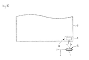
- Fig. 8 is a perspective view illustrating one example of a laundry RFID tag 1 (RFID tag for a flexible material product), which is a conventional RFID tag utilized by being attached to a laundry-related product (flexible material product) of various types that is reusable by cleaning after use in places such as hotels and company offices.
- the laundry RFID tag 1 includes a tag main body 2 and an RFID inlay 3 provided within the tag main body 2.
- the tag main body 2 is configured by a material with a required degree of flexibility and rigidity such as an isoprene rubber material formed into a cuboid, in which the RFID inlay 3 is molded.
- the RFID inlay 3 includes an inlay base 4 made, for example, of polyethylene terephthalate or a film stack of polyethylene terephthalate, an IC chip 5, and an RFID antenna 6.
- the RFID inlay 3 performs reading and writing of data required for the IC chip 5 wirelessly via the RFID antenna 6 (data communication) based on an electromagnetic effect of radio waves in a predetermined frequency band such as a UHF band (300 MHz to 3 GHz (preferably, 860 MHz to 960 MHz, more specifically, 433 MHz, 900 MHz, 915 MHz to 930 MHz, or 950 MHz to 956 MHz), microwaves (1 GHz to 30 GHz, specifically 2.45 GHz), or an HF band (3 MHz to 30 MHz (preferably, 13.56 MHz)), or at a frequency no higher than 135 kHz.
- a predetermined frequency band such as a UHF band (300 MHz to 3 GHz (preferably, 860 MHz to 960 MHz, more specifically, 433 MHz, 900 MHz, 915 MHz to 930 MHz, or 950 MHz to 956 MHz), microwaves (1 GHz to 30 GHz, specifically 2.45 GHz), or an HF band (3 MHz to
- a communication distance of a component using radio waves having a wavelength in the UHF band is typically on the order of 5 m to 10 m, and an application of such component in various fields is expected.
- Fig. 9 is a partially-omitted plan view illustrating the laundry RFID tag 1 attached to a laundry-related product (e. g., a sheet 7) that is repeatedly used. As shown in a partially-enlarged sectional view of the figure, the laundry RFID tag 1 is attached in such a manner that the laundry RFID tag 1 is contained within an attachment pocket 8 provided at one corner of the sheet 7.
- a laundry-related product e. g., a sheet 7
- the finished laundry RFID tag 1 thus configured is like a so-called rubber plate, and therefore it produces an absolute feeling of a foreign body when attached to working wear, uniforms, or other clothes other than the sheet 7.
- the laundry RFID tag 1 attached within the attachment pocket 8 poses a problem that the laundry RFID tag 1 gradually becomes exposed as a portion around the laundry RFID tag 1 or the attachment pocket 8 is susceptible to accumulation of damage during use of the sheet 7, as well as during collection and through steps of cleaning and pressing.
- the RFID antenna 6 of the laundry RFID tag 1 is configured by an extremely-thin metallic foil made of copper, aluminum, or the like, or by etching or the like, and there is a problem that the RFID antenna 6 is susceptible to disconnection. Accordingly, the tag main body 2 is made thick using a rubber-base material as described above so as to protect the RFID antenna 6.
- the laundry RFID tag 1 may not be sewn directly on clothing, a laundry-related product (the sheet 7), or the like, and requires a secondary component such as a backing cloth (not depicted) provided for the sheet 7 or secondary processing such as sewing the tag while placed in the attachment pocket 8.
- a secondary component such as a backing cloth (not depicted) provided for the sheet 7 or secondary processing such as sewing the tag while placed in the attachment pocket 8.
- the tag main body 2 is not made thick, there is a problem the thin RFID antenna 6 may be easily disconnected due to a stress such as bending or twisting in cleaning, resulting in a failure of the laundry RFID tag 1 itself.
- the present invention has been made in view of the above problems, and an object of the present invention is to provide an RFID tag for a flexible material product and attachable directly to the flexible material product, examples of which include various fabric products such as clothes and laundry-related products, soft synthetic resin material products, and leather products, an RFID antenna of the RFID tag for a flexible material product, and an RFID antenna continuous body for the RFID tag for a flexible material product.
- Another object of the present invention is to provide an RFID tag for a flexible material product and easily attachable to the flexible material product, an RFID antenna of the RFID tag for a flexible material product, and an RFID antenna continuous body for the RFID tag for a flexible material product.
- Yet another object of the present invention is to provide an RFID tag for a flexible material product and resistant to a stress such as bending or twisting in cleaning, an RFID antenna of the RFID tag for a flexible material product, and an RFID antenna continuous body for the RFID tag for a flexible material product.
- Yet another object of the present invention is to provide an RFID tag for a flexible material product and having an RFID antenna insusceptible to disconnection or performing data communication without any problem even when disconnection occurs, such an RFID antenna of the RFID tag for a flexible material product, and an RFID antenna continuous body for the RFID tag for a flexible material product.
- Yet another object of the present invention is to provide an RFID tag for a flexible material product, the tag being extremely close to the flexible material and exceptionally durable, an RFID antenna of the RFID tag for a flexible material product, and an RFID antenna continuous body for the RFID tag for a flexible material product.
- Yet another object of the present invention is to provide an RFID tag for a flexible material product and capable of realizing reduction of costs for materials, improvement of workability of the materials, and improvement of mass productivity, an RFID antenna of the RFID tag for a flexible material product, and an RFID antenna continuous body for the RFID tag for a flexible material product.
- Yet another object of the present invention is to provide an RFID tag for a flexible material product which tag may easily indicate identification for a backup of information and such and provides high flexibility in a design of an RFID antenna, such an RFID antenna of the RFID tag for a flexible material product, and an RFID antenna continuous body for the RFID tag for a flexible material product.
- the present invention focuses on a configuration in which the RFID antenna itself is made of a flexible material such as a fabric material, specifically, a configuration in which a tag base itself is made of a flexible material such as a fabric material or the like, and a configuration in which an antenna itself is configured by a conductive thread.
- a first aspect of the invention is an RFID tag for a flexible material product, the tag including: a tag base attachable to the flexible material product; and an RFID inlay provided for the tag base, having an IC chip and an RFID antenna, and capable of performing wireless data communication, wherein the tag base is configured by a flexible material, and the RFID antenna includes a base antenna portion configured by integrating a conductive thread into the tag base.
- a second aspect of the invention is an RFID antenna of an RFID tag for a flexible material product, the tag having a tag base attachable to the flexible material product and being capable of performing wireless data communication, wherein the tag base is configured by a flexible material, and the RFID antenna is configured by integrating a conductive thread into the tag base.
- a third aspect of the invention is an RFID antenna of an RFID tag for a flexible material product, the tag including: a tag base attachable to the flexible material product; and an RFID inlay provided for the tag base, having an IC chip and an RFID antenna, and capable of performing wireless data communication, wherein the tag base is configured by a flexible material, and the RFID antenna is configured by integrating a conductive thread into the tag base.
- a fourth aspect of the invention is an RFID antenna continuous body for an RFID tag for a flexible material product, the tag having a tag base attachable to the flexible material product and being capable of performing wireless data communication, wherein the tag base is configured by a strip-shaped flexible material, the RFID antenna continuous body is configured by providing a plurality of base antenna portions, each in a required antenna pattern, successively and repeatedly by integrating a conductive thread into the tag base, and the tag base is separable so as to separate the base antenna portions from each other.
- the RFID inlay may include: the IC chip; an inlay antenna portion connected to the IC chip; and a protecting member configured to protect the inlay antenna portion and the IC chip.
- the protecting member may be configured by a glass epoxy resin.
- the RFID antenna may be configured to work in electromagnetic cooperation with the inlay antenna portion included in the RFID inlay.
- the base antenna portion and the inlay antenna portion may be electromagneticaly couplable.
- the flexible material may be a fabric material.
- the conductive thread may be integrated into the tag base by one of weaving and sewing.
- the RFID inlay may be fixable to the tag base by an adhesive agent.
- the RFID inlay may be attachable to an attachment pocket provided for the tag base.
- the RFID inlay may be sewable on the tag base.
- the RFID antenna may include a base antenna portion configured by integrating the conductive thread into the tag base.
- the RFID inlay may include: the IC chip; and an inlay antenna portion connected to the IC chip, and the base antenna portion and the inlay antenna portion may be electromagneticaly couplable.
- the tag base is configured by a flexible material such as a fabric material or the like
- the RFID antenna is configured by integrating the conductive thread into the tag base using a common processing treatment such as weaving or sewing, and whereby non-contact data communication is enabled. Therefore, no sense of discomfort is provided or a stress is insusceptible to occur when the tag is attached to a flexible material product such as clothing. Thus, possibility of damages to the RFID antenna itself is reduced, and durability equivalent to that of the flexible material product may be provided.
- the RFID antenna of an RFID tag for a flexible material product of the second aspect of the invention may be provided with a simple processing treatment, as the tag base is configured by a flexible material, and the conductive thread is integrated into the tag base.
- the RFID antenna of an RFID tag for a flexible material product of the third aspect of the invention may perform wireless data communication in electromagnetic cooperation with the RFID inlay included in the RFID tag for a flexible material product, as the tag base is configured by a flexible material, and the conductive thread is integrated into the tag base.
- the tag base is configured by a strip-shaped flexible material, the plurality of base antenna portions each in a required antenna pattern are provided successively and repeatedly by integrating the conductive thread into the tag base, and the tag base is separable so as to separate the base antenna portions from each other. Therefore, it is possible to provide the RFID antenna of a portion length having a predetermined antenna pattern extremely easily.
- an RFID antenna is configured by a tag base made of a flexible material and a conductive thread integral with the tag base. Therefore, the RFID antenna itself is made of fabric so to speak.
- an RFID tag for a flexible material product that is suitable for data communication through processing such as direct sewing on a flexible material product such as clothing, an RFID antenna of the RFID tag for a flexible material product, and an RFID antenna continuous body for the RFID tag for a flexible material product.
- an RFID antenna 11A and an RFID antenna continuous body 11, as well as an RFID tag 10 for a flexible material product configured by these components according to an embodiment of the present invention will be described with reference to Fig. 1 through Fig. 7 .
- like components as illustrated in Fig. 8 and Fig. 9 are denoted by like reference numerals and detailed descriptions of these components shall be omitted.
- Fig. 1 is a perspective view illustrating the RFID antenna continuous body 11 for configuring the RFID tag 10 for a flexible material product that is capable of performing wireless data communication
- Fig. 2 is a plan view illustrating the RFID tag 10 for a flexible material product
- Fig. 3 is a sectional view illustrating the RFID tag 10 for a flexible material product.
- the RFID antenna continuous body 11 includes a strip-shaped tag base 12 and a plurality of base antenna portions 13 each in a required antenna pattern.
- the tag base 12 is configured by a strip-shaped flexible material such as a fabric material, a soft synthetic resin material, or a leather material, and may be attached to a flexible material product such as a fabric product such as clothing or a sheet 7, a soft synthetic resin material product, a leather product, or the like by a method such as sewing, adhesion, or the like.
- the tag base 12 may have any thickness (usually, relatively thin) depending on a use condition or a usage pattern of the RFID tag 10 for a flexible material product, and may be made of a material the same as or different from that of the flexible material product.
- the plurality of base antenna portions 13 are provided, each in an antenna pattern of an arbitrarily required design, successively and repeatedly by integrating a conductive thread 14 into the tag base 12 by weaving or sewing.
- the plurality of base antenna portions 13 may be easily provided successively by typical sewing while connection threads 14A of the conductive thread 14 are disposed on a back side of the tag base 12 as shown by a dashed line in Fig. 1 .
- the conductive thread 14 it is possible to sew the conductive thread 14 at an optionally set sewing density, that is, at an optionally set degree of closeness between adjacent parts of the conductive thread 14.
- an optionally set sewing density that is, at an optionally set degree of closeness between adjacent parts of the conductive thread 14.
- the tag base 12 may be cut so as to separate portions including the base antenna portions 13 from each other, for example, by a predetermined length (that is, a length required as the RFID tag 10 for a flexible material product) at portions of the connection threads 14A, and it is possible to easily provide the RFID antenna 11A of a unit length configured by integrating the conductive thread 14 into the tag base 12.
- a predetermined length that is, a length required as the RFID tag 10 for a flexible material product
- the RFID tag 10 for a flexible material product includes the RFID antenna 11A having the tag base 12 and the base antenna portion 13, and an RFID inlay 15.
- a portion of the conductive thread 14 for a portion of the conductive thread 14, a section along a sewing line is shown.
- the RFID inlay 15 is attached to the tag base 12 (i.e., the RFID antenna 11A) and serves as a core RFID tag material or a near-field inlay material.
- the RFID inlay 15 includes an IC chip 5, an inlay antenna portion 16 connected to the IC chip 5, and a protecting member 17 for protecting the inlay antenna portion 16 and the IC chip 5, and is able to perform wireless data communication.
- the inlay antenna portion 16 is made of copper, aluminum, or the like.
- the base antenna portion 13 by the conductive thread 14 and the inlay antenna portion 16 may be electromagnetically coupled (coupling of radio waves) especially when the radio waves in use are high-frequency waves in the UHF band or the like, and enable non-contact data communication the RFID tag 10 for a flexible material product as a whole.
- the inlay antenna portion 16 included in the RFID inlay 15 serves as an internal antenna portion
- the base antenna portion 13 included in the tag base 12 (the RFID antenna 11A) serves as an external antenna portion
- An RFID antenna portion 18 as the RFID tag 10 for a flexible material product as a whole includes the inlay antenna portion 16 and the base antenna portion 13, and the RFID antenna 11A (the base antenna portion 13) is able to work in electromagnetic cooperation with the inlay antenna portion 16 included in the RFID inlay 15.
- the protecting member 17 may be made of any hard material such as a glass epoxy resin, in a circular disk shape in the example shown in the figure ( Fig. 2 ), and may protect the IC chip 5 and the inlay antenna portion 16 from an external force of various types that is exerted on the RFID inlay 15 and in turn on the RFID antenna 11A as a whole.
- the RFID inlay 15 is fixed to the tag base 12 (the RFID antenna 11A), for example, by an adhesive agent 19, to form the RFID tag 10 for a flexible material product.
- Fig. 4 is an enlarged perspective view illustrating the conductive thread 14.
- the conductive thread 14 is configured such that a fiber thread 20 made of polyester, acrylic, or the like is integrated with a metal 21 such as copper or nickel so as to be provided with electrical conductivity and flexibility by a method such as plating, printing, or winding, and may be integrated into the tag base 12 by weaving or sewing in a predetermined antenna pattern as described above.
- Fig. 5 is an enlarged perspective view illustrating another configuration example of the conductive thread 14 (reinforced conductive thread 22).
- the conductive thread 14 is resistible to a tension due to weaving or sewing, for example, by winding a polyester thread 23 helically around a circumferential surface of the conductive thread 14 as needed.
- a first identification indication 24 as a code such as a bar code, a sign, or visibly seen letters and signs on the tag base 12 as information for backing up various data stored in the IC chip 5, or to similarly show a second identification indication 25 on the protecting member 17 of the RFID inlay 15.
- the conductive thread 14 is integrated into the tag base 12 to provide the base antenna portion 13 (the RFID antenna 11A), and as such a configuration may be achieved by simple weaving or sewing, it is possible to provide the RFID antenna continuous body 11 and the RFID antenna 11A extremely easily.
- the tag base 12 itself is made of a flexible material that is the same as or different from that of the flexible material product such as a fabric material including the sheet 7, or the like, when attached to the sheet 7, the RFID tag 10 for a flexible material product is integrated with cloth and maintains durability to a stress such as bending or like, similarly to the cloth.
- the protecting member 17 As the RFID inlay 15 is protected by the protecting member 17, it is possible to prevent the IC chip 5 and the inlay antenna portion 16 provided within the inlay from being damaged or being disconnected.
- the base antenna portion 13 (the conductive thread 14) of the RFID antenna 11A is insusceptible to disconnection.
- electromagnetic coupling coupling of radio waves
- the radio waves in use are high-frequency waves in the UHF band or the like, and there is no trouble in non-contact data communication of the RFID tag 10 for a flexible material product as a whole.
- the base antenna portion 13 is provided as a stitch work of the conductive thread 14, even when a part of the conductive thread 14 is disconnected, the conduction is maintained if the disconnected portions of the conductive thread 14 are in contact with each other across the disconnection, and it is rare occurrence that conduction of the base antenna portion 13 as a whole is impaired.
- the non-contact data communication function itself may not be lost even though its gain decreases, as the RFID inlay 15 itself includes the IC chip 5 and the inlay antenna portion 16.
- the RFID tag 10 for a flexible material product may be attached to an attachment target such as, not limited to a fabric material such as the sheet 7 or clothing, a product made of a flexible synthetic resin material, a leather material, or the like of various types, and therefore a use target of the RFID tag 10 for a flexible material product may be optionally selected.
- an attachment target such as, not limited to a fabric material such as the sheet 7 or clothing, a product made of a flexible synthetic resin material, a leather material, or the like of various types, and therefore a use target of the RFID tag 10 for a flexible material product may be optionally selected.
- a formation patter of the base antenna portion 13 (the RFID antenna 11A) by the conductive thread 14 may be optionally selected according to a usage mode, depending on radio waves to be used such as a dipole-type antenna pattern, a coiled pattern, or the like.
- the antenna pattern may be of an optional design on user's request. Processing for such a purpose may be weaving or sewing as described above, and it is possible to obtain an antenna pattern that is highly flexible, and excellent in workability and mass productivity.
- any optional configuration may be employed as an attachment configuration of the RFID tag 10 for a flexible material product to the flexible material product such as the sheet 7.
- Fig. 6 is a partially-omitted plan view of a configuration in which the RFID inlay 15 is attached to an attachment pocket 26 provided for the RFID antenna 11A (the tag base 12) to be attached to the sheet 7.
- the RFID inlay 15 may be simply placed in the RFID antenna 11A (the attachment pocket 26) without using the adhesive agent 19 or the like for integration with the RFID antenna 11A ( Fig. 3 ).
- Fig. 7 is a partially-omitted plan view of a configuration in which the RFID inlay 15 is sewn along with the RFID antenna 11A (the tag base 12) to be attached to the sheet 7.
- a sewing hole 28 like a button hole is previously provided in the protecting member 17 of the RFID inlay 15, and the RFID inlay 15 may be sewn on the tag base 12 along with the RFID antenna 11A by the sewing thread 27.
- this attachment configuration it is possible to attach the RFID antenna 11A and the RFID inlay 15 to the sheet 7 at the same time in the sewing step of the RFID antenna 11A to the sheet 7, and the attachment process may be performed in a highly efficient manner.
Landscapes
- Engineering & Computer Science (AREA)
- Physics & Mathematics (AREA)
- General Physics & Mathematics (AREA)
- Theoretical Computer Science (AREA)
- Computer Hardware Design (AREA)
- Microelectronics & Electronic Packaging (AREA)
- Computer Networks & Wireless Communication (AREA)
- Textile Engineering (AREA)
- Details Of Aerials (AREA)
- Woven Fabrics (AREA)
Abstract
Description
- The present invention relates to flexible material product RFID (Radio Frequency Identification: Radio Frequency Identification) tags, RFID antennas of the RFID tags for a flexible material product, and RFID antenna continuous bodies for the RFID tags for a flexible material product. The present invention relates in particular to an RFID tag for a flexible material product and attachable to the flexible material product, examples of which include various fabric products such as clothes and laundry-related products, an RFID antenna of the RFID tag for a flexible material product, and an RFID antenna continuous body for the RFID tag for a flexible material product.
- Conventionally, an RFID tag having an IC chip and an RFID antenna and capable of wirelessly writing or reading data has been utilized for data management of required data in various fields by attaching the tag to an article of various types and reading and writing various data relating to the article.
-
Fig. 8 is a perspective view illustrating one example of a laundry RFID tag 1 (RFID tag for a flexible material product), which is a conventional RFID tag utilized by being attached to a laundry-related product (flexible material product) of various types that is reusable by cleaning after use in places such as hotels and company offices. Thelaundry RFID tag 1 includes a tagmain body 2 and an RFID inlay 3 provided within the tagmain body 2. - The tag
main body 2 is configured by a material with a required degree of flexibility and rigidity such as an isoprene rubber material formed into a cuboid, in which the RFID inlay 3 is molded. - The RFID inlay 3 includes an inlay base 4 made, for example, of polyethylene terephthalate or a film stack of polyethylene terephthalate, an
IC chip 5, and anRFID antenna 6. - The RFID inlay 3 performs reading and writing of data required for the
IC chip 5 wirelessly via the RFID antenna 6 (data communication) based on an electromagnetic effect of radio waves in a predetermined frequency band such as a UHF band (300 MHz to 3 GHz (preferably, 860 MHz to 960 MHz, more specifically, 433 MHz, 900 MHz, 915 MHz to 930 MHz, or 950 MHz to 956 MHz), microwaves (1 GHz to 30 GHz, specifically 2.45 GHz), or an HF band (3 MHz to 30 MHz (preferably, 13.56 MHz)), or at a frequency no higher than 135 kHz. - However, specific configurations of the
IC chip 5 and theRFID antenna 6 are adjusted suitably depending on radio waves to be used by each component. - In particular, a communication distance of a component using radio waves having a wavelength in the UHF band (e.g., 860 MHz to 960 MHz) is typically on the order of 5 m to 10 m, and an application of such component in various fields is expected.
-
Fig. 9 is a partially-omitted plan view illustrating thelaundry RFID tag 1 attached to a laundry-related product (e. g., a sheet 7) that is repeatedly used. As shown in a partially-enlarged sectional view of the figure, thelaundry RFID tag 1 is attached in such a manner that thelaundry RFID tag 1 is contained within anattachment pocket 8 provided at one corner of thesheet 7. - The finished
laundry RFID tag 1 thus configured is like a so-called rubber plate, and therefore it produces an absolute feeling of a foreign body when attached to working wear, uniforms, or other clothes other than thesheet 7. In addition, thelaundry RFID tag 1 attached within theattachment pocket 8 poses a problem that thelaundry RFID tag 1 gradually becomes exposed as a portion around thelaundry RFID tag 1 or theattachment pocket 8 is susceptible to accumulation of damage during use of thesheet 7, as well as during collection and through steps of cleaning and pressing. - Further, the
RFID antenna 6 of thelaundry RFID tag 1 is configured by an extremely-thin metallic foil made of copper, aluminum, or the like, or by etching or the like, and there is a problem that theRFID antenna 6 is susceptible to disconnection. Accordingly, the tagmain body 2 is made thick using a rubber-base material as described above so as to protect theRFID antenna 6. - Therefore, there is a problem that the
laundry RFID tag 1 may not be sewn directly on clothing, a laundry-related product (the sheet 7), or the like, and requires a secondary component such as a backing cloth (not depicted) provided for thesheet 7 or secondary processing such as sewing the tag while placed in theattachment pocket 8. - On the other hand, if the tag
main body 2 is not made thick, there is a problem thethin RFID antenna 6 may be easily disconnected due to a stress such as bending or twisting in cleaning, resulting in a failure of thelaundry RFID tag 1 itself. - Furthermore, when a backing cloth (not depicted) is provided for the
sheet 7 or when the secondary processing such as sewing the tag while placed in theattachment pocket 8 is carried out, an entirety of the laundry RFID tag 1 (the tag main body 2) is covered by cloth and such. This poses a problem that it is not possible to attach a visually-seen indication for identification for a backup of information stored in theIC chip 5 to the laundry RFID tag 1 (the tag main body 2). - It should be noted that in order to provide an original design of the
RFID antenna 6 unique to a user of thelaundry RFID tag 1 on request, an extremely high initial cost is required and a frequency performance of thelaundry RFID tag 1 and influenced, and therefore there is another problem that it is difficult to respond to such a request. - PTL 1: Japanese Patent No.
4548074 - The present invention has been made in view of the above problems, and an object of the present invention is to provide an RFID tag for a flexible material product and attachable directly to the flexible material product, examples of which include various fabric products such as clothes and laundry-related products, soft synthetic resin material products, and leather products, an RFID antenna of the RFID tag for a flexible material product, and an RFID antenna continuous body for the RFID tag for a flexible material product.
- Another object of the present invention is to provide an RFID tag for a flexible material product and easily attachable to the flexible material product, an RFID antenna of the RFID tag for a flexible material product, and an RFID antenna continuous body for the RFID tag for a flexible material product.
- Yet another object of the present invention is to provide an RFID tag for a flexible material product and resistant to a stress such as bending or twisting in cleaning, an RFID antenna of the RFID tag for a flexible material product, and an RFID antenna continuous body for the RFID tag for a flexible material product.
- Yet another object of the present invention is to provide an RFID tag for a flexible material product and having an RFID antenna insusceptible to disconnection or performing data communication without any problem even when disconnection occurs, such an RFID antenna of the RFID tag for a flexible material product, and an RFID antenna continuous body for the RFID tag for a flexible material product.
- Yet another object of the present invention is to provide an RFID tag for a flexible material product, the tag being extremely close to the flexible material and exceptionally durable, an RFID antenna of the RFID tag for a flexible material product, and an RFID antenna continuous body for the RFID tag for a flexible material product.
- Yet another object of the present invention is to provide an RFID tag for a flexible material product and capable of realizing reduction of costs for materials, improvement of workability of the materials, and improvement of mass productivity, an RFID antenna of the RFID tag for a flexible material product, and an RFID antenna continuous body for the RFID tag for a flexible material product.
- Yet another object of the present invention is to provide an RFID tag for a flexible material product which tag may easily indicate identification for a backup of information and such and provides high flexibility in a design of an RFID antenna, such an RFID antenna of the RFID tag for a flexible material product, and an RFID antenna continuous body for the RFID tag for a flexible material product.
- Thus, the present invention focuses on a configuration in which the RFID antenna itself is made of a flexible material such as a fabric material, specifically, a configuration in which a tag base itself is made of a flexible material such as a fabric material or the like, and a configuration in which an antenna itself is configured by a conductive thread.
- A first aspect of the invention is an RFID tag for a flexible material product, the tag including: a tag base attachable to the flexible material product; and an RFID inlay provided for the tag base, having an IC chip and an RFID antenna, and capable of performing wireless data communication, wherein the tag base is configured by a flexible material, and the RFID antenna includes a base antenna portion configured by integrating a conductive thread into the tag base.
- A second aspect of the invention is an RFID antenna of an RFID tag for a flexible material product, the tag having a tag base attachable to the flexible material product and being capable of performing wireless data communication, wherein the tag base is configured by a flexible material, and the RFID antenna is configured by integrating a conductive thread into the tag base.
- A third aspect of the invention is an RFID antenna of an RFID tag for a flexible material product, the tag including: a tag base attachable to the flexible material product; and an RFID inlay provided for the tag base, having an IC chip and an RFID antenna, and capable of performing wireless data communication, wherein the tag base is configured by a flexible material, and the RFID antenna is configured by integrating a conductive thread into the tag base.
- A fourth aspect of the invention is an RFID antenna continuous body for an RFID tag for a flexible material product, the tag having a tag base attachable to the flexible material product and being capable of performing wireless data communication, wherein the tag base is configured by a strip-shaped flexible material, the RFID antenna continuous body is configured by providing a plurality of base antenna portions, each in a required antenna pattern, successively and repeatedly by integrating a conductive thread into the tag base, and the tag base is separable so as to separate the base antenna portions from each other.
- The RFID inlay may include: the IC chip; an inlay antenna portion connected to the IC chip; and a protecting member configured to protect the inlay antenna portion and the IC chip.
- The protecting member may be configured by a glass epoxy resin.
- The RFID antenna may be configured to work in electromagnetic cooperation with the inlay antenna portion included in the RFID inlay.
- The base antenna portion and the inlay antenna portion may be electromagneticaly couplable.
- The flexible material may be a fabric material.
- The conductive thread may be integrated into the tag base by one of weaving and sewing.
- The RFID inlay may be fixable to the tag base by an adhesive agent.
- The RFID inlay may be attachable to an attachment pocket provided for the tag base.
- The RFID inlay may be sewable on the tag base.
- The RFID antenna may include a base antenna portion configured by integrating the conductive thread into the tag base.
- The RFID inlay may include: the IC chip; and an inlay antenna portion connected to the IC chip, and the base antenna portion and the inlay antenna portion may be electromagneticaly couplable.
- According to the RFID tag for a flexible material product, the RFID antenna of the RFID tag for a flexible material product, and the RFID antenna continuous body for the RFID tag for a flexible material product of the present invention, the tag base is configured by a flexible material such as a fabric material or the like, the RFID antenna is configured by integrating the conductive thread into the tag base using a common processing treatment such as weaving or sewing, and whereby non-contact data communication is enabled. Therefore, no sense of discomfort is provided or a stress is insusceptible to occur when the tag is attached to a flexible material product such as clothing. Thus, possibility of damages to the RFID antenna itself is reduced, and durability equivalent to that of the flexible material product may be provided.
- In particular, the RFID antenna of an RFID tag for a flexible material product of the second aspect of the invention may be provided with a simple processing treatment, as the tag base is configured by a flexible material, and the conductive thread is integrated into the tag base.
- In particular, the RFID antenna of an RFID tag for a flexible material product of the third aspect of the invention may perform wireless data communication in electromagnetic cooperation with the RFID inlay included in the RFID tag for a flexible material product, as the tag base is configured by a flexible material, and the conductive thread is integrated into the tag base.
- In particular, according to the RFID antenna continuous body for the RFID tag for a flexible material product of the fourth aspect of the invention, the tag base is configured by a strip-shaped flexible material, the plurality of base antenna portions each in a required antenna pattern are provided successively and repeatedly by integrating the conductive thread into the tag base, and the tag base is separable so as to separate the base antenna portions from each other. Therefore, it is possible to provide the RFID antenna of a portion length having a predetermined antenna pattern extremely easily.
-
-
Fig. 1 is a perspective view illustrating an RFID antennacontinuous body 11 for configuring anRFID tag 10 for a flexible material product according to an embodiment of the present invention, showing the perspective view illustrating the RFID antennacontinuous body 11 according to the embodiment of the present invention. -
Fig. 2 is a plan view illustrating theRFID tag 10 for a flexible material product according to the embodiment of the present invention. -
Fig. 3 is a sectional view illustrating theRFID tag 10 for a flexible material product according to the embodiment of the present invention. -
Fig. 4 is an enlarged perspective view illustrating aconductive thread 14 according to the embodiment of the present invention. -
Fig. 5 is an enlarged perspective view illustrating another configuration example of the conductive thread 14 (a reinforced conductive thread 22) according to the embodiment of the present invention. -
Fig. 6 is a partially-omitted plan view illustrating a configuration in which anRFID inlay 15 is attached to anattachment pocket 26 provided for anRFID antenna 11A (a tag base 12) to be attached to asheet 7 according to the embodiment of the present invention. -
Fig. 7 is a partially-omitted plan view illustrating a configuration in which theRFID inlay 15 is sewn along with theRFID antenna 11A (the tag base 12) to be attached to thesheet 7 according to the embodiment of the present invention. -
Fig. 8 is a perspective view illustrating one example of a laundry RFID tag 1 (RFID tag for a flexible material product), which is a conventional RFID tag utilized by being attached to a laundry-related product (flexible material product) of various types that is reusable by cleaning after use in places such as hotels and company offices. -
Fig. 9 is a partially-omitted plan view illustrating thelaundry RFID tag 1 attached to a laundry-related product (e. g., the sheet 7) that is repeatedly used. - According to the present invention, an RFID antenna is configured by a tag base made of a flexible material and a conductive thread integral with the tag base. Therefore, the RFID antenna itself is made of fabric so to speak. Thus, there are realized an RFID tag for a flexible material product that is suitable for data communication through processing such as direct sewing on a flexible material product such as clothing, an RFID antenna of the RFID tag for a flexible material product, and an RFID antenna continuous body for the RFID tag for a flexible material product.
- Hereinafter, an
RFID antenna 11A and an RFID antennacontinuous body 11, as well as anRFID tag 10 for a flexible material product configured by these components according to an embodiment of the present invention will be described with reference toFig. 1 through Fig. 7 . However, like components as illustrated inFig. 8 andFig. 9 are denoted by like reference numerals and detailed descriptions of these components shall be omitted. -
Fig. 1 is a perspective view illustrating the RFID antennacontinuous body 11 for configuring theRFID tag 10 for a flexible material product that is capable of performing wireless data communication,Fig. 2 is a plan view illustrating theRFID tag 10 for a flexible material product, andFig. 3 is a sectional view illustrating theRFID tag 10 for a flexible material product. - The RFID antenna
continuous body 11 includes a strip-shapedtag base 12 and a plurality ofbase antenna portions 13 each in a required antenna pattern. - The
tag base 12 is configured by a strip-shaped flexible material such as a fabric material, a soft synthetic resin material, or a leather material, and may be attached to a flexible material product such as a fabric product such as clothing or asheet 7, a soft synthetic resin material product, a leather product, or the like by a method such as sewing, adhesion, or the like. - The
tag base 12 may have any thickness (usually, relatively thin) depending on a use condition or a usage pattern of theRFID tag 10 for a flexible material product, and may be made of a material the same as or different from that of the flexible material product. - The plurality of
base antenna portions 13 are provided, each in an antenna pattern of an arbitrarily required design, successively and repeatedly by integrating aconductive thread 14 into thetag base 12 by weaving or sewing. - For example, when the
conductive thread 14 is sewn on thetag base 12 like a stitch work by sewing, the plurality ofbase antenna portions 13 may be easily provided successively by typical sewing whileconnection threads 14A of theconductive thread 14 are disposed on a back side of thetag base 12 as shown by a dashed line inFig. 1 . - In addition, it is possible to sew the
conductive thread 14 at an optionally set sewing density, that is, at an optionally set degree of closeness between adjacent parts of theconductive thread 14. By closely sewing theconductive thread 14, even if a part of the thread is disconnected, a contact state between the disconnected parts of theconductive thread 14 may be maintained. Therefore, it is possible to prevent a trouble in the data communication from occurring. - According to the RFID antenna
continuous body 11 thus configured, after thebase antenna portions 13 are integrated into thetag base 12, thetag base 12 may be cut so as to separate portions including thebase antenna portions 13 from each other, for example, by a predetermined length (that is, a length required as theRFID tag 10 for a flexible material product) at portions of theconnection threads 14A, and it is possible to easily provide theRFID antenna 11A of a unit length configured by integrating theconductive thread 14 into thetag base 12. - As illustrated specifically in
Fig. 2 andFig. 3 , theRFID tag 10 for a flexible material product includes theRFID antenna 11A having thetag base 12 and thebase antenna portion 13, and anRFID inlay 15. InFig. 3 , for a portion of theconductive thread 14, a section along a sewing line is shown. - The
RFID inlay 15 is attached to the tag base 12 (i.e., theRFID antenna 11A) and serves as a core RFID tag material or a near-field inlay material. TheRFID inlay 15 includes anIC chip 5, aninlay antenna portion 16 connected to theIC chip 5, and a protectingmember 17 for protecting theinlay antenna portion 16 and theIC chip 5, and is able to perform wireless data communication. - The
inlay antenna portion 16 is made of copper, aluminum, or the like. Thebase antenna portion 13 by theconductive thread 14 and theinlay antenna portion 16 may be electromagnetically coupled (coupling of radio waves) especially when the radio waves in use are high-frequency waves in the UHF band or the like, and enable non-contact data communication theRFID tag 10 for a flexible material product as a whole. - Specifically, the
inlay antenna portion 16 included in theRFID inlay 15 serves as an internal antenna portion, and thebase antenna portion 13 included in the tag base 12 (theRFID antenna 11A) serves as an external antenna portion. AnRFID antenna portion 18 as theRFID tag 10 for a flexible material product as a whole includes theinlay antenna portion 16 and thebase antenna portion 13, and theRFID antenna 11A (the base antenna portion 13) is able to work in electromagnetic cooperation with theinlay antenna portion 16 included in theRFID inlay 15. - The protecting
member 17 may be made of any hard material such as a glass epoxy resin, in a circular disk shape in the example shown in the figure (Fig. 2 ), and may protect theIC chip 5 and theinlay antenna portion 16 from an external force of various types that is exerted on theRFID inlay 15 and in turn on theRFID antenna 11A as a whole. - As illustrated specifically in
Fig. 3 , theRFID inlay 15 is fixed to the tag base 12 (theRFID antenna 11A), for example, by anadhesive agent 19, to form theRFID tag 10 for a flexible material product. -
Fig. 4 is an enlarged perspective view illustrating theconductive thread 14. Theconductive thread 14 is configured such that afiber thread 20 made of polyester, acrylic, or the like is integrated with ametal 21 such as copper or nickel so as to be provided with electrical conductivity and flexibility by a method such as plating, printing, or winding, and may be integrated into thetag base 12 by weaving or sewing in a predetermined antenna pattern as described above. - Further,
Fig. 5 is an enlarged perspective view illustrating another configuration example of the conductive thread 14 (reinforced conductive thread 22). Theconductive thread 14 is resistible to a tension due to weaving or sewing, for example, by winding apolyester thread 23 helically around a circumferential surface of theconductive thread 14 as needed. - Here, as illustrated specifically in
Fig. 2 andFig. 3 , it is possible to show afirst identification indication 24 as a code such as a bar code, a sign, or visibly seen letters and signs on thetag base 12 as information for backing up various data stored in theIC chip 5, or to similarly show asecond identification indication 25 on the protectingmember 17 of theRFID inlay 15. - According to the
RFID tag 10 for a flexible material product and the RFID antennacontinuous body 11 thus configured, as theconductive thread 14 is integrated into thetag base 12 to provide the base antenna portion 13 (theRFID antenna 11A), and as such a configuration may be achieved by simple weaving or sewing, it is possible to provide the RFID antennacontinuous body 11 and theRFID antenna 11A extremely easily. - In addition, by simply providing the
RFID inlay 15 for theRFID antenna 11A (the tag base 12) so that theRFID inlay 15 and theRFID antenna 11A (the base antenna portion 13) are close to each other, it is possible to allow a non-contact data communication function of theRFID tag 10 for a flexible material product to be fully delivered. - Further, as the
tag base 12 itself is made of a flexible material that is the same as or different from that of the flexible material product such as a fabric material including thesheet 7, or the like, when attached to thesheet 7, theRFID tag 10 for a flexible material product is integrated with cloth and maintains durability to a stress such as bending or like, similarly to the cloth. - As the
RFID inlay 15 is protected by the protectingmember 17, it is possible to prevent theIC chip 5 and theinlay antenna portion 16 provided within the inlay from being damaged or being disconnected. - It should be appreciated that by employing a material that is soft and rigid other than the glass epoxy resin as the protecting
member 17, it is possible to deliver a further flexible protecting function, as well as to expand a range of application of theRFID tag 10 for a flexible material product. - As described above, the base antenna portion 13 (the conductive thread 14) of the
RFID antenna 11A is insusceptible to disconnection. However, even if a part of theconductive thread 14 is disconnected, electromagnetic coupling (coupling of radio waves) with each other may be maintained especially when the radio waves in use are high-frequency waves in the UHF band or the like, and there is no trouble in non-contact data communication of theRFID tag 10 for a flexible material product as a whole. - However, as the
base antenna portion 13 is provided as a stitch work of theconductive thread 14, even when a part of theconductive thread 14 is disconnected, the conduction is maintained if the disconnected portions of theconductive thread 14 are in contact with each other across the disconnection, and it is rare occurrence that conduction of thebase antenna portion 13 as a whole is impaired. - Further, even when disconnection of the
base antenna portion 13 occurs, the non-contact data communication function itself may not be lost even though its gain decreases, as theRFID inlay 15 itself includes theIC chip 5 and theinlay antenna portion 16. - Moreover, the
RFID tag 10 for a flexible material product may be attached to an attachment target such as, not limited to a fabric material such as thesheet 7 or clothing, a product made of a flexible synthetic resin material, a leather material, or the like of various types, and therefore a use target of theRFID tag 10 for a flexible material product may be optionally selected. - Furthermore, a formation patter of the base antenna portion 13 (the
RFID antenna 11A) by theconductive thread 14 may be optionally selected according to a usage mode, depending on radio waves to be used such as a dipole-type antenna pattern, a coiled pattern, or the like. In addition, the antenna pattern may be of an optional design on user's request. Processing for such a purpose may be weaving or sewing as described above, and it is possible to obtain an antenna pattern that is highly flexible, and excellent in workability and mass productivity. - Further, any optional configuration may be employed as an attachment configuration of the
RFID tag 10 for a flexible material product to the flexible material product such as thesheet 7. -
Fig. 6 , for example, is a partially-omitted plan view of a configuration in which theRFID inlay 15 is attached to anattachment pocket 26 provided for theRFID antenna 11A (the tag base 12) to be attached to thesheet 7. - As shown specifically in a partially-enlarged sectional view, by sewing the
tag base 12 of theRFID tag 10 for a flexible material product on thesheet 7 by asewing thread 27, providing theattachment pocket 26 for theRFID antenna 11A (the tag base 12) by thesewing thread 27, and placing and fixing theRFID inlay 15 in and to theattachment pocket 26 so as to become closer to thebase antenna portion 13 of theRFID antenna 11A, it is possible to cause theRFID tag 10 for a flexible material product as it is to deliver the data communication function. - According to this attachment configuration, the
RFID inlay 15 may be simply placed in theRFID antenna 11A (the attachment pocket 26) without using theadhesive agent 19 or the like for integration with theRFID antenna 11A (Fig. 3 ). -
Fig. 7 is a partially-omitted plan view of a configuration in which theRFID inlay 15 is sewn along with theRFID antenna 11A (the tag base 12) to be attached to thesheet 7. - As shown specifically in a partially-enlarged sectional view, a
sewing hole 28 like a button hole is previously provided in the protectingmember 17 of theRFID inlay 15, and theRFID inlay 15 may be sewn on thetag base 12 along with theRFID antenna 11A by thesewing thread 27. - According to this attachment configuration, it is possible to attach the
RFID antenna 11A and theRFID inlay 15 to thesheet 7 at the same time in the sewing step of theRFID antenna 11A to thesheet 7, and the attachment process may be performed in a highly efficient manner. -
- 1: Laundry RFID Tag (Conventional Example,
Fig. 8 ) - 2: Tag Main Body
- 3: RFID Inlay
- 4: Inlay Base
- 5: IC Chip
- 6: RFID Antenna
- 7: Sheet (Laundry-Related Product, Flexible Material Product,
Fig. 9 ) - 8: Attachment Pocket
- 10: RFID Tag for Flexible Material Product (Embodiment,
Fig. 2 ,Fig. 3 ) - 11: RFID Antenna Continuous Body (
Fig. 1 ) - 11A: RFID Antenna of Unit Length Separated from RFID Antenna Continuous Body 11 (Embodiment,
Fig. 2 ,Fig. 3 ) - 12: Tag Base
- 13: Base Antenna Portion
- 14: Conductive Thread
- 14A: Connection Thread of Conductive Thread 14 (
Fig. 1 ) - 15: RFID Inlay
- 16: Inlay Antenna Portion
- 17: Protecting Member
- 18: RFID Antenna Portion
- 19: Adhesive Agent
- 20: Fiber Thread Made of Polyester, Acrylic, or the like
- 21: Metal such as Copper or Nickel
- 22: Reinforced Conductive Thread (Conductive Thread)
- 23: Polyester Thread
- 24: First Identification Indication
- 25: Second Identification Indication
- 26: Attachment Pocket (
Fig. 6 ) - 27: Sewing Thread
- 28: Sewing Hole (
Fig. 7 )
Claims (21)
- An RFID tag for a flexible material product, the tag comprising:a tag base attachable to a flexible material product; andan RFID inlay provided for the tag base, having an IC chip and an RFID antenna, and capable of performing wireless data communication, whereinthe tag base is configured by a flexible material, andthe RFID antenna includes a base antenna portion configured by integrating a conductive thread into the tag base.
- The RFID tag for a flexible material product according to claim 1, wherein
the RFID inlay includes:the IC chip;an inlay antenna portion connected to the IC chip; anda protecting member configured to protect the inlay antenna portion and the IC chip. - The RFID tag for a flexible material product according to claim 2, wherein
the protecting member is configured by a glass epoxy resin. - The RFID tag for a flexible material product according to one of claim 2 and 3, wherein
the RFID antenna is conf igured to work in electromagnetic cooperation with the inlay antenna portion included in the RFID inlay. - The RFID tag for a flexible material product according to one of claims 2 to 4, wherein
the base antenna portion and the inlay antenna portion are electromagneticaly couplable. - The RFID tag for a flexible material product according to one of claims 1 to 5, wherein
the flexible material is a fabric material. - The RFID tag for a flexible material product according to one of claims 1 to 6, wherein
the conductive thread is integrated into the tag base by one of weaving and sewing. - The RFID tag for a flexible material product according to one of claims 1 to 7, wherein
the RFID inlay is fixable to the tag base by an adhesive agent. - The RFID tag for a flexible material product according to one of claims 1 to 7, wherein
the RFID inlay is attachable to an attachment pocket provided for the tag base. - The RFID tag for a flexible material product according to one of claims 1 to 7, wherein
the RFID inlay is sewable on the tag base. - An RFID antenna of an RFID tag for a flexible material product, the tag having a tag base attachable to the flexible material product and being capable of performing wireless data communication, wherein
the tag base is configured by a flexible material, and
the RFID antenna is configured by integrating a conductive thread into the tag base. - An RFID antenna of an RFID tag for a flexible material product, the tag comprising:a tag base attachable to a flexible material product; andan RFID inlay provided for the tag base, having an IC chip and an RFID antenna, and capable of performing wireless data communication, whereinthe tag base is configured by a flexible material, andthe RFID antenna is configured by integrating a conductive thread into the tag base.
- The RFID antenna of an RFID tag for a flexible material product according to one of claim 11 and 12, wherein
the RFID antenna includes a base antenna portion configured by integrating the conductive thread into the tag base. - The RFID antenna of an RFID tag for a flexible material product according to one of claim 12 and 13, wherein
the RFID inlay includes:the IC chip;an inlay antenna portion connected to the IC chip; anda protecting member configured to protect the inlay antenna portion and the IC chip. - The RFID antenna of an RFID tag for a flexible material product according to one of claim 12 and 13, wherein
the RFID inlay includes:the IC chip; andan inlay antenna portion connected to the IC chip, andthe base antenna portion and the inlay antenna portion are electromagneticaly couplable. - The RFID antenna of an RFID tag for a flexible material product according to one of claim 11 to 15, wherein
the flexible material is a fabric material. - The RFID antenna of an RFID tag for a flexible material product according to one of claim 11 to 16, wherein
the conductive thread is integrated into the tag base by one of weaving and sewing. - The RFID antenna of an RFID tag for a flexible material product according to one of claim 12 to 17, wherein
the RFID inlay is fixable to the tag base by an adhesive agent. - The RFID antenna of an RFID tag for a flexible material product according to one of claim 12 to 17, wherein
the RFID inlay is attachable to an attachment pocket provided for the tag base. - The RFID antenna of an RFID tag for a flexible material product according to one of claim 12 to 17, wherein
the RFID inlay is sewable on the tag base. - An RFID antenna continuous body for an RFID tag for a flexible material product, the tag having a tag base attachable to the flexible material product and being capable of performing wireless data communication, wherein
the tag base is configured by a strip-shaped flexible material,
the RFID antenna continuous body is configured by providing a plurality of base antenna portions, each in a required antenna pattern, successively and repeatedly by integrating a conductive thread into the tag base, and
the tag base is separable so as to separate the base antenna portions from each other.
Applications Claiming Priority (3)
| Application Number | Priority Date | Filing Date | Title |
|---|---|---|---|
| JP2011235910A JP5850704B2 (en) | 2011-10-27 | 2011-10-27 | RFID antenna for RFID tag for flexible material products |
| JP2011235909A JP5850703B2 (en) | 2011-10-27 | 2011-10-27 | RFID tag for flexible material products |
| PCT/JP2012/006840 WO2013061592A1 (en) | 2011-10-27 | 2012-10-25 | Rfid tag for flexible material product, rfid antenna of rfid tag for flexible material product, and rfid antenna continuum of same |
Publications (3)
| Publication Number | Publication Date |
|---|---|
| EP2772873A1 true EP2772873A1 (en) | 2014-09-03 |
| EP2772873A4 EP2772873A4 (en) | 2015-07-01 |
| EP2772873B1 EP2772873B1 (en) | 2019-12-18 |
Family
ID=48167443
Family Applications (1)
| Application Number | Title | Priority Date | Filing Date |
|---|---|---|---|
| EP12843533.6A Active EP2772873B1 (en) | 2011-10-27 | 2012-10-25 | Rfid tag for a flexible material product |
Country Status (3)
| Country | Link |
|---|---|
| US (1) | US9064199B2 (en) |
| EP (1) | EP2772873B1 (en) |
| WO (1) | WO2013061592A1 (en) |
Cited By (10)
| Publication number | Priority date | Publication date | Assignee | Title |
|---|---|---|---|---|
| FR3036823A1 (en) * | 2015-06-01 | 2016-12-02 | Tagsys | RADIO-IDENTIFICATION ARRANGEMENT FOR TEXTILE ARTICLE AND CORRESPONDING MOUNTING METHOD |
| ITUB20155495A1 (en) * | 2015-11-11 | 2017-05-11 | Consiglio Nazionale Ricerche | DEVICE OF THE TYPE OF AN ANTENNA, A HEATER, AN ELECTROMAGNETIC SCREEN, AND SIMILAR, PROCESS OF REALIZING DEVICES OF THE TYPE OF AN ANTENNA, A HEATER, AN ELECTROMAGNETIC SCREEN, AN ELECTRIC AND SIMILAR INTERCONNECTION, SEMI-FINISHED LAMINAR SEMI-FINISHED FOR THE REALIZATION OF DEVICES OF THE TYPE OF AN ANTENNA, A HEATER, AN ELECTROMAGNETIC SCREEN, AN ELECTRIC INTERCONNECTION, A CIRCUIT AND THE LIKE. |
| WO2018094065A1 (en) * | 2016-11-16 | 2018-05-24 | Avery Dennison Retail Information Services, Llc | Programming and testing of wire rfid tags |
| EP3640850A1 (en) * | 2018-10-16 | 2020-04-22 | Relytex GmbH & Co. KG | Rfid system and method for the preparation of a rfid system |
| FR3103043A1 (en) * | 2019-11-08 | 2021-05-14 | Primo1D | ELECTRONIC IDENTIFICATION LABEL INCLUDING A WIRED ELECTRONIC IDENTIFICATION DEVICE, PROCESS FOR MANUFACTURING SUCH A LABEL AND TEXTILE PART WITH SUCH A LABEL. |
| FR3103293A1 (en) * | 2019-11-19 | 2021-05-21 | Commissariat A L'energie Atomique Et Aux Energies Alternatives | RFID tag |
| IT202000013294A1 (en) * | 2020-06-04 | 2021-12-04 | Datamars Sa | Method of manufacturing a marker for a fabric |
| EP4303761A1 (en) * | 2022-07-07 | 2024-01-10 | Kordsa Teknik Tekstil Anonim Sirketi | A contactlessly activated rfid tag for a tire |
| US12086667B2 (en) | 2019-12-28 | 2024-09-10 | Avery Dennison Retail Information Services Llc | Wireless communication device having a stiffness altering structure |
| WO2025054420A1 (en) * | 2023-09-08 | 2025-03-13 | Sensormatic Electronics, LLC | Rfid label with stitched wire |
Families Citing this family (36)
| Publication number | Priority date | Publication date | Assignee | Title |
|---|---|---|---|---|
| EP2779029B1 (en) * | 2013-03-13 | 2017-07-26 | SES RFID Solutions GmbH | Chip card inlay for contact and non-contact responsive smart cards |
| JP2014191712A (en) * | 2013-03-28 | 2014-10-06 | Toppan Forms Co Ltd | Noncontact data reception/transmission body |
| WO2014204322A1 (en) * | 2013-06-19 | 2014-12-24 | Ross Robert Clarke | Radio frequency identification tag |
| US9246208B2 (en) | 2013-08-06 | 2016-01-26 | Hand Held Products, Inc. | Electrotextile RFID antenna |
| US9684864B1 (en) * | 2015-02-05 | 2017-06-20 | Flextronics Ap, Llc. | Method of making RFID antenna by placing wire on fabric |
| US10096217B2 (en) * | 2016-05-11 | 2018-10-09 | Braeburn Asset Holdings, Llc | Security system and security tag assembly |
| US11229553B2 (en) * | 2016-08-16 | 2022-01-25 | Synaptive Medical Inc. | Dressing apparatus and methods for facilitating healing |
| US9886661B1 (en) | 2016-11-03 | 2018-02-06 | Smarthin Technologies, Inc. | RFID tag and methods of use and manufacture |
| WO2018088406A1 (en) * | 2016-11-10 | 2018-05-17 | 株式会社村田製作所 | Rfid tag and method for manufacturing rfid tag |
| WO2018089777A2 (en) | 2016-11-10 | 2018-05-17 | Eco Culture Manufacturing Corp | Garment life cycle tracking system and method |
| WO2018165146A1 (en) | 2017-03-06 | 2018-09-13 | Cummins Filtration Ip, Inc. | Genuine filter recognition with filter monitoring system |
| US10534988B2 (en) | 2017-08-18 | 2020-01-14 | Avery Dennison Retail Information Services Llc | Durable RFID printed fabric labels |
| JP6384938B1 (en) * | 2017-10-03 | 2018-09-05 | 創造技術株式会社 | Leather composite material |
| JP6562193B1 (en) * | 2018-01-23 | 2019-08-21 | 株式会社村田製作所 | RFID tag, article provided with RFID tag, and method of manufacturing article |
| WO2019222139A1 (en) * | 2018-05-14 | 2019-11-21 | The General Hospital Corporation | Wireless-enabled surgical suture needle |
| US11282357B2 (en) | 2018-05-22 | 2022-03-22 | Tyco Fire & Security Gmbh | Elongate flexible tag |
| CN214044006U (en) * | 2018-08-17 | 2021-08-24 | 株式会社村田制作所 | Articles with wireless communication devices |
| TWM572188U (en) * | 2018-09-26 | 2019-01-01 | 合隆毛廠股份有限公司 | Inductive quilt |
| EP3664217A1 (en) * | 2018-12-03 | 2020-06-10 | Amann & Söhne GmbH & Co. KG | Antenna |
| IT201900003659A1 (en) * | 2019-03-13 | 2020-09-13 | Barbara Vignali | RFID antenna for textile supports and respective method of application |
| IT201900003653A1 (en) * | 2019-03-13 | 2020-09-13 | Technores S R L | RFID antenna for flexible media and respective method of application |
| CN110647966B (en) * | 2019-08-08 | 2024-06-21 | 深圳盈达信息科技有限公司 | Electronic tag, radio frequency identification system and item counting method |
| US12223814B2 (en) | 2019-09-16 | 2025-02-11 | Sensormatic Electronics, LLC | Security tag for textiles using conductive thread |
| US10970613B1 (en) | 2019-09-18 | 2021-04-06 | Sensormatic Electronics, LLC | Systems and methods for providing tags adapted to be incorporated with or in items |
| US11443160B2 (en) | 2019-09-18 | 2022-09-13 | Sensormatic Electronics, LLC | Systems and methods for laser tuning and attaching RFID tags to products |
| US11055588B2 (en) | 2019-11-27 | 2021-07-06 | Sensormatic Electronics, LLC | Flexible water-resistant sensor tag |
| US12524640B2 (en) | 2019-11-27 | 2026-01-13 | Sensormatic Electronics, LLC | Flexible water-resistant sensor tag |
| US11694057B2 (en) | 2020-01-03 | 2023-07-04 | Sensormatic Electronics, LLC | RFID tag and method of making same |
| EP3958177B1 (en) | 2020-08-17 | 2026-05-06 | TexTrace AG | Textile rfid transponder and method for applying a textile rfid transponder to textiles |
| CN112598101A (en) * | 2020-12-18 | 2021-04-02 | 浙江凯瑞博科技有限公司 | Washable electronic tag integrated with RFID antenna and manufacturing method thereof |
| FR3119944B1 (en) * | 2021-02-15 | 2023-02-10 | Primo1D | Radiofrequency transmission-reception device using an antenna composed of a textile yarn and a conductive tape and associated electronic tag |
| US11755874B2 (en) | 2021-03-03 | 2023-09-12 | Sensormatic Electronics, LLC | Methods and systems for heat applied sensor tag |
| CN113592052A (en) * | 2021-08-23 | 2021-11-02 | 上海华苑电子有限公司 | Novel passive ultrahigh frequency radio frequency washing label |
| US11869324B2 (en) | 2021-12-23 | 2024-01-09 | Sensormatic Electronics, LLC | Securing a security tag into an article |
| US12536401B2 (en) | 2022-08-31 | 2026-01-27 | Sensormatic Electronics, LLC | Security tag |
| WO2025136933A1 (en) * | 2023-12-22 | 2025-06-26 | Sensormatic Electronics, LLC | Electronic article surveillance tag with thread antenna |
Family Cites Families (20)
| Publication number | Priority date | Publication date | Assignee | Title |
|---|---|---|---|---|
| JP4015717B2 (en) * | 1995-06-29 | 2007-11-28 | 日立マクセル株式会社 | Information carrier manufacturing method |
| DE102004003461C5 (en) * | 2004-01-22 | 2009-11-19 | ASTRA Gesellschaft für Asset Management mbH & Co. KG | Textile material with an HF transponder |
| DE102004005017A1 (en) * | 2004-01-30 | 2005-09-01 | ASTRA Gesellschaft für Asset Management mbH & Co. KG | Textile material with antenna components of an HF transponder |
| TW200614591A (en) * | 2004-09-14 | 2006-05-01 | Textilma Ag | Textile strip comprising an integrated antenna thread for an RF transponder |
| JP4548074B2 (en) | 2004-09-30 | 2010-09-22 | 凸版印刷株式会社 | IC tag for cleaning |
| BRPI0607472A2 (en) * | 2005-02-23 | 2009-09-08 | Textilma Ag | transponder wire as well as your job |
| DE102005008397B4 (en) * | 2005-02-24 | 2013-07-18 | Avery Dennison Rinke Gmbh | Woven label |
| JP4771115B2 (en) * | 2005-04-27 | 2011-09-14 | 日立化成工業株式会社 | IC tag |
| WO2007009273A1 (en) * | 2005-07-22 | 2007-01-25 | Textilma Ag | Textile sheet material, especially label, comprising a chip |
| DE102006011596A1 (en) * | 2006-03-10 | 2007-09-13 | Mühlbauer Ag | Method for fixing and contacting RFID chip modules for producing transponders with a textile substrate and transponders for textile fabrics |
| DE102007016584B4 (en) * | 2006-06-23 | 2023-05-04 | ASTRA Gesellschaft für Asset Management mbH & Co. KG | textile information carrier |
| EP1870797B2 (en) * | 2006-06-23 | 2020-10-07 | ASTRA Gesellschaft für Asset Management mbH & Co. KG | Textile information carrier |
| US20100051699A1 (en) * | 2006-09-18 | 2010-03-04 | Francisco Speich | Rfid textile label |
| US7999683B2 (en) * | 2007-03-23 | 2011-08-16 | Zih Corp. | RFID tag with reduced detuning characteristics |
| DE102007017864A1 (en) * | 2007-04-13 | 2008-10-16 | ASTRA Gesellschaft für Asset Management mbH & Co. KG | Method and device for protection against remote readout of product identification data |
| DE102008046338B4 (en) * | 2008-07-10 | 2012-10-31 | Gera-Ident Gmbh | Identification means for a contactless data transmission and manufacturing method thereof |
| US8339267B2 (en) * | 2008-09-26 | 2012-12-25 | Avery Dennison Corporation | RFID device having protective cap element and method of making |
| JP2011015395A (en) | 2009-06-03 | 2011-01-20 | Nippon Information System:Kk | Cloth with rfid tag, and system for managing cloth with rfid tag |
| US8593256B2 (en) * | 2009-06-23 | 2013-11-26 | Avery Dennison Corporation | Washable RFID device for apparel tracking |
| US20140103116A1 (en) * | 2011-03-24 | 2014-04-17 | Tagsys Sas | Rfid tag assembly and label process |
-
2012
- 2012-10-25 WO PCT/JP2012/006840 patent/WO2013061592A1/en not_active Ceased
- 2012-10-25 EP EP12843533.6A patent/EP2772873B1/en active Active
- 2012-10-25 US US14/353,264 patent/US9064199B2/en active Active
Cited By (18)
| Publication number | Priority date | Publication date | Assignee | Title |
|---|---|---|---|---|
| FR3036823A1 (en) * | 2015-06-01 | 2016-12-02 | Tagsys | RADIO-IDENTIFICATION ARRANGEMENT FOR TEXTILE ARTICLE AND CORRESPONDING MOUNTING METHOD |
| ITUB20155495A1 (en) * | 2015-11-11 | 2017-05-11 | Consiglio Nazionale Ricerche | DEVICE OF THE TYPE OF AN ANTENNA, A HEATER, AN ELECTROMAGNETIC SCREEN, AND SIMILAR, PROCESS OF REALIZING DEVICES OF THE TYPE OF AN ANTENNA, A HEATER, AN ELECTROMAGNETIC SCREEN, AN ELECTRIC AND SIMILAR INTERCONNECTION, SEMI-FINISHED LAMINAR SEMI-FINISHED FOR THE REALIZATION OF DEVICES OF THE TYPE OF AN ANTENNA, A HEATER, AN ELECTROMAGNETIC SCREEN, AN ELECTRIC INTERCONNECTION, A CIRCUIT AND THE LIKE. |
| WO2017081195A1 (en) * | 2015-11-11 | 2017-05-18 | Consiglio Nazionale Delle Ricerche | Device of the type of an antenna, a heater, an electromagnetic screen and the like, process for providing devices of the type of an antenna, a heater, an electromagnetic screen, an electrical interconnection and the like, a substantially laminar blank for providing devices of the type of an antenna, a heater, an electromagnetic screen, an electrical interconnection, a circuit and the like |
| US11017185B2 (en) | 2016-11-16 | 2021-05-25 | Avery Dennison Retail Information Services Llc | Programming and testing of wire RFID tags |
| WO2018094065A1 (en) * | 2016-11-16 | 2018-05-24 | Avery Dennison Retail Information Services, Llc | Programming and testing of wire rfid tags |
| EP3640850A1 (en) * | 2018-10-16 | 2020-04-22 | Relytex GmbH & Co. KG | Rfid system and method for the preparation of a rfid system |
| WO2021089939A1 (en) * | 2019-11-08 | 2021-05-14 | Primo1D | Textile part provided with an electronic tag comprising a wired electronic device and method for producing such a part |
| FR3103043A1 (en) * | 2019-11-08 | 2021-05-14 | Primo1D | ELECTRONIC IDENTIFICATION LABEL INCLUDING A WIRED ELECTRONIC IDENTIFICATION DEVICE, PROCESS FOR MANUFACTURING SUCH A LABEL AND TEXTILE PART WITH SUCH A LABEL. |
| EP4336406A3 (en) * | 2019-11-08 | 2024-06-19 | Primo1D | Textile part provided with an electronic tag comprising a wire-based electronic device, method for manufacturing such a part |
| FR3103293A1 (en) * | 2019-11-19 | 2021-05-21 | Commissariat A L'energie Atomique Et Aux Energies Alternatives | RFID tag |
| EP3825917A1 (en) * | 2019-11-19 | 2021-05-26 | Commissariat à l'Energie Atomique et aux Energies Alternatives | Radio-identification label |
| US12086667B2 (en) | 2019-12-28 | 2024-09-10 | Avery Dennison Retail Information Services Llc | Wireless communication device having a stiffness altering structure |
| IT202000013294A1 (en) * | 2020-06-04 | 2021-12-04 | Datamars Sa | Method of manufacturing a marker for a fabric |
| WO2021245567A1 (en) * | 2020-06-04 | 2021-12-09 | Datamars Sa | Method for manufacturing a tag for a textile |
| US11861443B2 (en) | 2020-06-04 | 2024-01-02 | Datamars Sa | Method for manufacturing a tag for a textile |
| EP4398151A3 (en) * | 2020-06-04 | 2024-09-11 | Datamars SA | Method for manufacturing a tag for a textile |
| EP4303761A1 (en) * | 2022-07-07 | 2024-01-10 | Kordsa Teknik Tekstil Anonim Sirketi | A contactlessly activated rfid tag for a tire |
| WO2025054420A1 (en) * | 2023-09-08 | 2025-03-13 | Sensormatic Electronics, LLC | Rfid label with stitched wire |
Also Published As
| Publication number | Publication date |
|---|---|
| EP2772873B1 (en) | 2019-12-18 |
| US9064199B2 (en) | 2015-06-23 |
| WO2013061592A1 (en) | 2013-05-02 |
| EP2772873A4 (en) | 2015-07-01 |
| US20140291409A1 (en) | 2014-10-02 |
Similar Documents
| Publication | Publication Date | Title |
|---|---|---|
| US9064199B2 (en) | RFID tag for flexible material product, RFID antenna of RFID tag for flexible material product, and RFID antenna continuum of same | |
| JP5850704B2 (en) | RFID antenna for RFID tag for flexible material products | |
| JP5850703B2 (en) | RFID tag for flexible material products | |
| EP2689382B1 (en) | Rfid tag assembly and label process | |
| US9058554B2 (en) | Transponder with tamper protection | |
| JP5939830B2 (en) | RFID tag | |
| US8267325B2 (en) | Wristband with elastic portion and inelastic portion containing a RFID inlay | |
| EP2504796B1 (en) | Rfid apparel tag for use in industrial processing and post care treatment | |
| US10733495B2 (en) | Wearable RFID device | |
| KR101311547B1 (en) | Rfid tag | |
| JP5369337B2 (en) | Composite yarn and fabric provided with the same | |
| CN106462780B (en) | Product tags incorporating durable antennas | |
| EP2804132B1 (en) | Rfid tag and method of attachment thereof | |
| CA2764749A1 (en) | Washable rfid device for apparel tracking | |
| JP5939831B2 (en) | RFID tag | |
| JP5939832B2 (en) | RFID antenna for RFID tag | |
| EP3528176B1 (en) | Contactless smart ring device | |
| EP3956814B1 (en) | Rfid device and method of manufacturing the same | |
| JP2007018487A (en) | Ic tag | |
| CN205486209U (en) | Water -fast RFID radio -frequency identification label who washes can buckle many times | |
| JP2001167240A (en) | Ic tag | |
| US12254365B2 (en) | RFID tag for being fastened to a textile | |
| KR101169699B1 (en) | Sheet type rfid tag | |
| CN219676602U (en) | High-flexibility anti-metal RFID electronic tag | |
| KR200406501Y1 (en) | RFID tagged book |
Legal Events
| Date | Code | Title | Description |
|---|---|---|---|
| PUAI | Public reference made under article 153(3) epc to a published international application that has entered the european phase |
Free format text: ORIGINAL CODE: 0009012 |
|
| 17P | Request for examination filed |
Effective date: 20140423 |
|
| AK | Designated contracting states |
Kind code of ref document: A1 Designated state(s): AL AT BE BG CH CY CZ DE DK EE ES FI FR GB GR HR HU IE IS IT LI LT LU LV MC MK MT NL NO PL PT RO RS SE SI SK SM TR |
|
| DAX | Request for extension of the european patent (deleted) | ||
| RA4 | Supplementary search report drawn up and despatched (corrected) |
Effective date: 20150603 |
|
| RIC1 | Information provided on ipc code assigned before grant |
Ipc: G06K 19/07 20060101ALI20150528BHEP Ipc: G09F 3/00 20060101ALI20150528BHEP Ipc: G06K 19/077 20060101AFI20150528BHEP Ipc: H01Q 1/38 20060101ALI20150528BHEP |
|
| 17Q | First examination report despatched |
Effective date: 20160217 |
|
| STAA | Information on the status of an ep patent application or granted ep patent |
Free format text: STATUS: EXAMINATION IS IN PROGRESS |
|
| GRAP | Despatch of communication of intention to grant a patent |
Free format text: ORIGINAL CODE: EPIDOSNIGR1 |
|
| STAA | Information on the status of an ep patent application or granted ep patent |
Free format text: STATUS: GRANT OF PATENT IS INTENDED |
|
| INTG | Intention to grant announced |
Effective date: 20190716 |
|
| RAP1 | Party data changed (applicant data changed or rights of an application transferred) |
Owner name: SATO HOLDINGS KABUSHIKI KAISHA |
|
| GRAS | Grant fee paid |
Free format text: ORIGINAL CODE: EPIDOSNIGR3 |
|
| GRAA | (expected) grant |
Free format text: ORIGINAL CODE: 0009210 |
|
| STAA | Information on the status of an ep patent application or granted ep patent |
Free format text: STATUS: THE PATENT HAS BEEN GRANTED |
|
| AK | Designated contracting states |
Kind code of ref document: B1 Designated state(s): AL AT BE BG CH CY CZ DE DK EE ES FI FR GB GR HR HU IE IS IT LI LT LU LV MC MK MT NL NO PL PT RO RS SE SI SK SM TR |
|
| REG | Reference to a national code |
Ref country code: GB Ref legal event code: FG4D |
|
| REG | Reference to a national code |
Ref country code: CH Ref legal event code: EP |
|
| REG | Reference to a national code |
Ref country code: IE Ref legal event code: FG4D |
|
| REG | Reference to a national code |
Ref country code: DE Ref legal event code: R096 Ref document number: 602012066619 Country of ref document: DE |
|
| REG | Reference to a national code |
Ref country code: AT Ref legal event code: REF Ref document number: 1215414 Country of ref document: AT Kind code of ref document: T Effective date: 20200115 |
|
| REG | Reference to a national code |
Ref country code: NL Ref legal event code: MP Effective date: 20191218 |
|
| PG25 | Lapsed in a contracting state [announced via postgrant information from national office to epo] |
Ref country code: GR Free format text: LAPSE BECAUSE OF FAILURE TO SUBMIT A TRANSLATION OF THE DESCRIPTION OR TO PAY THE FEE WITHIN THE PRESCRIBED TIME-LIMIT Effective date: 20200319 Ref country code: NO Free format text: LAPSE BECAUSE OF FAILURE TO SUBMIT A TRANSLATION OF THE DESCRIPTION OR TO PAY THE FEE WITHIN THE PRESCRIBED TIME-LIMIT Effective date: 20200318 Ref country code: BG Free format text: LAPSE BECAUSE OF FAILURE TO SUBMIT A TRANSLATION OF THE DESCRIPTION OR TO PAY THE FEE WITHIN THE PRESCRIBED TIME-LIMIT Effective date: 20200318 Ref country code: FI Free format text: LAPSE BECAUSE OF FAILURE TO SUBMIT A TRANSLATION OF THE DESCRIPTION OR TO PAY THE FEE WITHIN THE PRESCRIBED TIME-LIMIT Effective date: 20191218 Ref country code: LV Free format text: LAPSE BECAUSE OF FAILURE TO SUBMIT A TRANSLATION OF THE DESCRIPTION OR TO PAY THE FEE WITHIN THE PRESCRIBED TIME-LIMIT Effective date: 20191218 Ref country code: SE Free format text: LAPSE BECAUSE OF FAILURE TO SUBMIT A TRANSLATION OF THE DESCRIPTION OR TO PAY THE FEE WITHIN THE PRESCRIBED TIME-LIMIT Effective date: 20191218 Ref country code: LT Free format text: LAPSE BECAUSE OF FAILURE TO SUBMIT A TRANSLATION OF THE DESCRIPTION OR TO PAY THE FEE WITHIN THE PRESCRIBED TIME-LIMIT Effective date: 20191218 |
|
| REG | Reference to a national code |
Ref country code: LT Ref legal event code: MG4D |
|
| PG25 | Lapsed in a contracting state [announced via postgrant information from national office to epo] |
Ref country code: HR Free format text: LAPSE BECAUSE OF FAILURE TO SUBMIT A TRANSLATION OF THE DESCRIPTION OR TO PAY THE FEE WITHIN THE PRESCRIBED TIME-LIMIT Effective date: 20191218 Ref country code: RS Free format text: LAPSE BECAUSE OF FAILURE TO SUBMIT A TRANSLATION OF THE DESCRIPTION OR TO PAY THE FEE WITHIN THE PRESCRIBED TIME-LIMIT Effective date: 20191218 |
|
| PG25 | Lapsed in a contracting state [announced via postgrant information from national office to epo] |
Ref country code: AL Free format text: LAPSE BECAUSE OF FAILURE TO SUBMIT A TRANSLATION OF THE DESCRIPTION OR TO PAY THE FEE WITHIN THE PRESCRIBED TIME-LIMIT Effective date: 20191218 |
|
| PG25 | Lapsed in a contracting state [announced via postgrant information from national office to epo] |
Ref country code: PT Free format text: LAPSE BECAUSE OF FAILURE TO SUBMIT A TRANSLATION OF THE DESCRIPTION OR TO PAY THE FEE WITHIN THE PRESCRIBED TIME-LIMIT Effective date: 20200513 Ref country code: EE Free format text: LAPSE BECAUSE OF FAILURE TO SUBMIT A TRANSLATION OF THE DESCRIPTION OR TO PAY THE FEE WITHIN THE PRESCRIBED TIME-LIMIT Effective date: 20191218 Ref country code: CZ Free format text: LAPSE BECAUSE OF FAILURE TO SUBMIT A TRANSLATION OF THE DESCRIPTION OR TO PAY THE FEE WITHIN THE PRESCRIBED TIME-LIMIT Effective date: 20191218 Ref country code: NL Free format text: LAPSE BECAUSE OF FAILURE TO SUBMIT A TRANSLATION OF THE DESCRIPTION OR TO PAY THE FEE WITHIN THE PRESCRIBED TIME-LIMIT Effective date: 20191218 Ref country code: RO Free format text: LAPSE BECAUSE OF FAILURE TO SUBMIT A TRANSLATION OF THE DESCRIPTION OR TO PAY THE FEE WITHIN THE PRESCRIBED TIME-LIMIT Effective date: 20191218 |
|
| PG25 | Lapsed in a contracting state [announced via postgrant information from national office to epo] |
Ref country code: IS Free format text: LAPSE BECAUSE OF FAILURE TO SUBMIT A TRANSLATION OF THE DESCRIPTION OR TO PAY THE FEE WITHIN THE PRESCRIBED TIME-LIMIT Effective date: 20200418 Ref country code: SM Free format text: LAPSE BECAUSE OF FAILURE TO SUBMIT A TRANSLATION OF THE DESCRIPTION OR TO PAY THE FEE WITHIN THE PRESCRIBED TIME-LIMIT Effective date: 20191218 Ref country code: SK Free format text: LAPSE BECAUSE OF FAILURE TO SUBMIT A TRANSLATION OF THE DESCRIPTION OR TO PAY THE FEE WITHIN THE PRESCRIBED TIME-LIMIT Effective date: 20191218 |
|
| REG | Reference to a national code |
Ref country code: DE Ref legal event code: R097 Ref document number: 602012066619 Country of ref document: DE |
|
| REG | Reference to a national code |
Ref country code: AT Ref legal event code: MK05 Ref document number: 1215414 Country of ref document: AT Kind code of ref document: T Effective date: 20191218 |
|
| PLBE | No opposition filed within time limit |
Free format text: ORIGINAL CODE: 0009261 |
|
| STAA | Information on the status of an ep patent application or granted ep patent |
Free format text: STATUS: NO OPPOSITION FILED WITHIN TIME LIMIT |
|
| PG25 | Lapsed in a contracting state [announced via postgrant information from national office to epo] |
Ref country code: DK Free format text: LAPSE BECAUSE OF FAILURE TO SUBMIT A TRANSLATION OF THE DESCRIPTION OR TO PAY THE FEE WITHIN THE PRESCRIBED TIME-LIMIT Effective date: 20191218 Ref country code: ES Free format text: LAPSE BECAUSE OF FAILURE TO SUBMIT A TRANSLATION OF THE DESCRIPTION OR TO PAY THE FEE WITHIN THE PRESCRIBED TIME-LIMIT Effective date: 20191218 |
|
| 26N | No opposition filed |
Effective date: 20200921 |
|
| PG25 | Lapsed in a contracting state [announced via postgrant information from national office to epo] |
Ref country code: AT Free format text: LAPSE BECAUSE OF FAILURE TO SUBMIT A TRANSLATION OF THE DESCRIPTION OR TO PAY THE FEE WITHIN THE PRESCRIBED TIME-LIMIT Effective date: 20191218 Ref country code: SI Free format text: LAPSE BECAUSE OF FAILURE TO SUBMIT A TRANSLATION OF THE DESCRIPTION OR TO PAY THE FEE WITHIN THE PRESCRIBED TIME-LIMIT Effective date: 20191218 |
|
| PG25 | Lapsed in a contracting state [announced via postgrant information from national office to epo] |
Ref country code: IT Free format text: LAPSE BECAUSE OF FAILURE TO SUBMIT A TRANSLATION OF THE DESCRIPTION OR TO PAY THE FEE WITHIN THE PRESCRIBED TIME-LIMIT Effective date: 20191218 |
|
| PG25 | Lapsed in a contracting state [announced via postgrant information from national office to epo] |
Ref country code: PL Free format text: LAPSE BECAUSE OF FAILURE TO SUBMIT A TRANSLATION OF THE DESCRIPTION OR TO PAY THE FEE WITHIN THE PRESCRIBED TIME-LIMIT Effective date: 20191218 |
|
| REG | Reference to a national code |
Ref country code: CH Ref legal event code: PL |
|
| PG25 | Lapsed in a contracting state [announced via postgrant information from national office to epo] |
Ref country code: MC Free format text: LAPSE BECAUSE OF FAILURE TO SUBMIT A TRANSLATION OF THE DESCRIPTION OR TO PAY THE FEE WITHIN THE PRESCRIBED TIME-LIMIT Effective date: 20191218 Ref country code: LU Free format text: LAPSE BECAUSE OF NON-PAYMENT OF DUE FEES Effective date: 20201025 |
|
| REG | Reference to a national code |
Ref country code: BE Ref legal event code: MM Effective date: 20201031 |
|
| PG25 | Lapsed in a contracting state [announced via postgrant information from national office to epo] |
Ref country code: CH Free format text: LAPSE BECAUSE OF NON-PAYMENT OF DUE FEES Effective date: 20201031 Ref country code: BE Free format text: LAPSE BECAUSE OF NON-PAYMENT OF DUE FEES Effective date: 20201031 Ref country code: LI Free format text: LAPSE BECAUSE OF NON-PAYMENT OF DUE FEES Effective date: 20201031 |
|
| PG25 | Lapsed in a contracting state [announced via postgrant information from national office to epo] |
Ref country code: IE Free format text: LAPSE BECAUSE OF NON-PAYMENT OF DUE FEES Effective date: 20201025 |
|
| PG25 | Lapsed in a contracting state [announced via postgrant information from national office to epo] |
Ref country code: TR Free format text: LAPSE BECAUSE OF FAILURE TO SUBMIT A TRANSLATION OF THE DESCRIPTION OR TO PAY THE FEE WITHIN THE PRESCRIBED TIME-LIMIT Effective date: 20191218 Ref country code: MT Free format text: LAPSE BECAUSE OF FAILURE TO SUBMIT A TRANSLATION OF THE DESCRIPTION OR TO PAY THE FEE WITHIN THE PRESCRIBED TIME-LIMIT Effective date: 20191218 Ref country code: CY Free format text: LAPSE BECAUSE OF FAILURE TO SUBMIT A TRANSLATION OF THE DESCRIPTION OR TO PAY THE FEE WITHIN THE PRESCRIBED TIME-LIMIT Effective date: 20191218 |
|
| PG25 | Lapsed in a contracting state [announced via postgrant information from national office to epo] |
Ref country code: MK Free format text: LAPSE BECAUSE OF FAILURE TO SUBMIT A TRANSLATION OF THE DESCRIPTION OR TO PAY THE FEE WITHIN THE PRESCRIBED TIME-LIMIT Effective date: 20191218 |
|
| P01 | Opt-out of the competence of the unified patent court (upc) registered |
Effective date: 20230411 |
|
| PGFP | Annual fee paid to national office [announced via postgrant information from national office to epo] |
Ref country code: DE Payment date: 20251021 Year of fee payment: 14 |
|
| PGFP | Annual fee paid to national office [announced via postgrant information from national office to epo] |
Ref country code: GB Payment date: 20251022 Year of fee payment: 14 |
|
| PGFP | Annual fee paid to national office [announced via postgrant information from national office to epo] |
Ref country code: FR Payment date: 20251030 Year of fee payment: 14 |