EP2772719B1 - Optische Vorrichtung - Google Patents
Optische Vorrichtung Download PDFInfo
- Publication number
- EP2772719B1 EP2772719B1 EP14000634.7A EP14000634A EP2772719B1 EP 2772719 B1 EP2772719 B1 EP 2772719B1 EP 14000634 A EP14000634 A EP 14000634A EP 2772719 B1 EP2772719 B1 EP 2772719B1
- Authority
- EP
- European Patent Office
- Prior art keywords
- light source
- optical
- target
- missile
- detection device
- Prior art date
- Legal status (The legal status is an assumption and is not a legal conclusion. Google has not performed a legal analysis and makes no representation as to the accuracy of the status listed.)
- Active
Links
- 230000003287 optical effect Effects 0.000 title claims description 98
- 238000001514 detection method Methods 0.000 claims description 59
- 238000000034 method Methods 0.000 claims description 13
- 230000005855 radiation Effects 0.000 claims description 9
- 238000005259 measurement Methods 0.000 claims description 6
- 230000001747 exhibiting effect Effects 0.000 claims 3
- 239000004020 conductor Substances 0.000 claims 1
- 230000001427 coherent effect Effects 0.000 description 3
- 238000011156 evaluation Methods 0.000 description 2
- 238000005286 illumination Methods 0.000 description 2
- 230000033001 locomotion Effects 0.000 description 2
- 238000010276 construction Methods 0.000 description 1
- 230000003247 decreasing effect Effects 0.000 description 1
- 230000001419 dependent effect Effects 0.000 description 1
- 238000013461 design Methods 0.000 description 1
- 238000011161 development Methods 0.000 description 1
- 230000018109 developmental process Effects 0.000 description 1
- 239000003365 glass fiber Substances 0.000 description 1
- 238000003384 imaging method Methods 0.000 description 1
- 238000004519 manufacturing process Methods 0.000 description 1
- 239000003550 marker Substances 0.000 description 1
- 239000000203 mixture Substances 0.000 description 1
- 230000010287 polarization Effects 0.000 description 1
- 230000008685 targeting Effects 0.000 description 1
- 230000000007 visual effect Effects 0.000 description 1
Images
Classifications
-
- F—MECHANICAL ENGINEERING; LIGHTING; HEATING; WEAPONS; BLASTING
- F41—WEAPONS
- F41G—WEAPON SIGHTS; AIMING
- F41G7/00—Direction control systems for self-propelled missiles
- F41G7/20—Direction control systems for self-propelled missiles based on continuous observation of target position
- F41G7/22—Homing guidance systems
- F41G7/2273—Homing guidance systems characterised by the type of waves
- F41G7/2293—Homing guidance systems characterised by the type of waves using electromagnetic waves other than radio waves
-
- F—MECHANICAL ENGINEERING; LIGHTING; HEATING; WEAPONS; BLASTING
- F41—WEAPONS
- F41G—WEAPON SIGHTS; AIMING
- F41G7/00—Direction control systems for self-propelled missiles
- F41G7/008—Combinations of different guidance systems
-
- F—MECHANICAL ENGINEERING; LIGHTING; HEATING; WEAPONS; BLASTING
- F41—WEAPONS
- F41G—WEAPON SIGHTS; AIMING
- F41G7/00—Direction control systems for self-propelled missiles
- F41G7/20—Direction control systems for self-propelled missiles based on continuous observation of target position
- F41G7/22—Homing guidance systems
- F41G7/2246—Active homing systems, i.e. comprising both a transmitter and a receiver
-
- F—MECHANICAL ENGINEERING; LIGHTING; HEATING; WEAPONS; BLASTING
- F41—WEAPONS
- F41G—WEAPON SIGHTS; AIMING
- F41G7/00—Direction control systems for self-propelled missiles
- F41G7/20—Direction control systems for self-propelled missiles based on continuous observation of target position
- F41G7/22—Homing guidance systems
- F41G7/2253—Passive homing systems, i.e. comprising a receiver and do not requiring an active illumination of the target
-
- G—PHYSICS
- G01—MEASURING; TESTING
- G01J—MEASUREMENT OF INTENSITY, VELOCITY, SPECTRAL CONTENT, POLARISATION, PHASE OR PULSE CHARACTERISTICS OF INFRARED, VISIBLE OR ULTRAVIOLET LIGHT; COLORIMETRY; RADIATION PYROMETRY
- G01J5/00—Radiation pyrometry, e.g. infrared or optical thermometry
- G01J5/10—Radiation pyrometry, e.g. infrared or optical thermometry using electric radiation detectors
-
- G—PHYSICS
- G01—MEASURING; TESTING
- G01S—RADIO DIRECTION-FINDING; RADIO NAVIGATION; DETERMINING DISTANCE OR VELOCITY BY USE OF RADIO WAVES; LOCATING OR PRESENCE-DETECTING BY USE OF THE REFLECTION OR RERADIATION OF RADIO WAVES; ANALOGOUS ARRANGEMENTS USING OTHER WAVES
- G01S17/00—Systems using the reflection or reradiation of electromagnetic waves other than radio waves, e.g. lidar systems
- G01S17/02—Systems using the reflection of electromagnetic waves other than radio waves
- G01S17/06—Systems determining position data of a target
- G01S17/08—Systems determining position data of a target for measuring distance only
- G01S17/32—Systems determining position data of a target for measuring distance only using transmission of continuous waves, whether amplitude-, frequency-, or phase-modulated, or unmodulated
-
- G—PHYSICS
- G01—MEASURING; TESTING
- G01S—RADIO DIRECTION-FINDING; RADIO NAVIGATION; DETERMINING DISTANCE OR VELOCITY BY USE OF RADIO WAVES; LOCATING OR PRESENCE-DETECTING BY USE OF THE REFLECTION OR RERADIATION OF RADIO WAVES; ANALOGOUS ARRANGEMENTS USING OTHER WAVES
- G01S17/00—Systems using the reflection or reradiation of electromagnetic waves other than radio waves, e.g. lidar systems
- G01S17/02—Systems using the reflection of electromagnetic waves other than radio waves
- G01S17/06—Systems determining position data of a target
- G01S17/42—Simultaneous measurement of distance and other co-ordinates
-
- G—PHYSICS
- G01—MEASURING; TESTING
- G01S—RADIO DIRECTION-FINDING; RADIO NAVIGATION; DETERMINING DISTANCE OR VELOCITY BY USE OF RADIO WAVES; LOCATING OR PRESENCE-DETECTING BY USE OF THE REFLECTION OR RERADIATION OF RADIO WAVES; ANALOGOUS ARRANGEMENTS USING OTHER WAVES
- G01S17/00—Systems using the reflection or reradiation of electromagnetic waves other than radio waves, e.g. lidar systems
- G01S17/02—Systems using the reflection of electromagnetic waves other than radio waves
- G01S17/50—Systems of measurement based on relative movement of target
- G01S17/58—Velocity or trajectory determination systems; Sense-of-movement determination systems
-
- G—PHYSICS
- G01—MEASURING; TESTING
- G01S—RADIO DIRECTION-FINDING; RADIO NAVIGATION; DETERMINING DISTANCE OR VELOCITY BY USE OF RADIO WAVES; LOCATING OR PRESENCE-DETECTING BY USE OF THE REFLECTION OR RERADIATION OF RADIO WAVES; ANALOGOUS ARRANGEMENTS USING OTHER WAVES
- G01S17/00—Systems using the reflection or reradiation of electromagnetic waves other than radio waves, e.g. lidar systems
- G01S17/86—Combinations of lidar systems with systems other than lidar, radar or sonar, e.g. with direction finders
-
- G—PHYSICS
- G01—MEASURING; TESTING
- G01S—RADIO DIRECTION-FINDING; RADIO NAVIGATION; DETERMINING DISTANCE OR VELOCITY BY USE OF RADIO WAVES; LOCATING OR PRESENCE-DETECTING BY USE OF THE REFLECTION OR RERADIATION OF RADIO WAVES; ANALOGOUS ARRANGEMENTS USING OTHER WAVES
- G01S7/00—Details of systems according to groups G01S13/00, G01S15/00, G01S17/00
- G01S7/48—Details of systems according to groups G01S13/00, G01S15/00, G01S17/00 of systems according to group G01S17/00
- G01S7/481—Constructional features, e.g. arrangements of optical elements
- G01S7/4811—Constructional features, e.g. arrangements of optical elements common to transmitter and receiver
- G01S7/4812—Constructional features, e.g. arrangements of optical elements common to transmitter and receiver transmitted and received beams following a coaxial path
Definitions
- the present invention relates to an optical device, in particular for use in search heads of missiles.
- Passive infrared seekers for missiles are known from the prior art, which can detect, for example, missiles or other target objects to be detected on the basis of their optical signature. These signatures represent the distribution of reflected or emitted radiation intensity on the target surface. They allow for recognition of target objects by the seeker and their coarse location in two-dimensional angular space, but provide only very inaccurate information about the state of motion, the distance and the three-dimensional shape of these targets.
- the accuracy of the results could be improved by measuring their distance to the seeker head at high resolution and their relative movement in all three degrees of freedom. Also, by capturing the depth dimension of the subject object in question, along with the attitude angular velocity measurement, classification and target false target discrimination could be supported.
- radar sensors help to significantly improve the information about target objects.
- radar sensors are difficult to integrate into a seeker head and, for example, are often provided as external sensors independent of the seeker head.
- An optical device is known from DE 32 19 533 A1 known. Furthermore, from the US 2006/0231771 A1 a LIDAR system is known, with the air targets can be detected. Finally, the reveals DE 29 08 231 A1 a targeting method in which a laser beam automatically tracks the target while serving as a friend-enemy detection signal, missile guidance, and target marker.
- the object is achieved by the features of claim 1.
- This comprises an optical device, which can be used in particular in a seeker head of a missile.
- the optical device comprises at least one optical sensor with a plurality of pixels, at least one light source, at least one detection device and an optical system.
- the light source according to the invention is set up such that it illuminates an object through the optical system.
- the object can be imaged by the optical system at least on a partial area of a predefined pixel of the optical sensor.
- the light source and the optical sensor are coupled, which means that it is known from the outset in the optical device which pixel of the optical sensor images that region of the environment that can be illuminated by the light source.
- This optical (axis) harmonization is preferably realized by a retroreflector, via which the light source can illuminate the optical sensor with a suitable wavelength. If the area to be illuminated is smaller than one pixel of the optical sensor, then the light source together with the detection device is preferably arranged to determine that part of the pixel which maps the area, i. determine the placement angle of the target with subpixel accuracy.
- the detection device is set up to detect the light emitted by the light source and reflected by the object. In particular, the detection device is set up to detect the reflected light through the optical system.
- the optical device makes it possible, by means of a Doppler evaluation, to determine the speed and / or the speed profile of the object.
- the optical device preferably forms a very compact component that can be used in a seeker head of a missile.
- the invention relates to a method for operating a seeker head of a missile, wherein the seeker head comprises at least one optical sensor with a plurality of pixels, at least one light source and at least one detection device. Furthermore, the seeker includes an optical system, wherein the light source is arranged to illuminate an object through the optical system, and wherein the object is imaged by the optical system at least on a predefined pixel of the optical sensor. Furthermore, the detection device is set up to detect the light emitted by the light source and reflected by the object.
- the method according to the invention comprises the following steps: First, a target is detected by means of the optical sensor or preferably by means of an infrared sensor, and a first direction in which the target is located relative to the missile is output.
- a distance between target and missile falls below a first predefined value.
- the target is illuminated by the light source as soon as the distance between target and missile falls below a second predefined value.
- the light emitted by the light source and reflected by the target light is then detected by the detection device.
- a distance between target and missile is determined and / or a second direction in which the target is located relative to the missile, and / or, in particular by means of Doppler method, a relative speed between target and, in particular by means of transit time measurement and / or modulation method Missile determined.
- the first direction represents only a coarse direction in which the target is relative to the missile, while the second direction represents in particular a more accurate direction indication than the first direction.
- the optical sensor can preferably detect where the target is relative to the missile, while by means of the light source and the detection device, an accurate measurement can be performed within the direction predetermined by the optical sensor.
- the second direction can therefore be determined very quickly, since the light source and the detection device are already essentially informed about where the target must be located.
- the illumination of the target by means of the light source and the detection of the reflected light advantageously provide precise information about the relative speed and / or the distance and / or the distinction between target and false target on the basis of Doppler profiles and / or in-range profiles to disposal.
- a large amount of information can be made available to a missile so that precise guidance of the missile to the target becomes possible.
- the light source is a laser source.
- the laser source is an infrared laser source.
- the laser source can emit coherent continuous and / or coherent pulsed radiation with high peak power. In this way, the range with which the detection device can detect reflected light of the light source can be increased.
- the detection device may preferably determine the transit time of the individual pulses in order to thus carry out distance measurements. Further, by further examining the reflected light of the light source, the detection device may preferably provide data necessary for determining the relative velocity of the object to the optical device.
- the optical device is advantageously configured such that the optical system has a dichroic beam splitter which is set up to separate optical radiation from the optical sensor or the detection device from a common beam path and / or is set up, the light from the light source into the common beam path to integrate.
- a dichroic beam splitter which is set up to separate optical radiation from the optical sensor or the detection device from a common beam path and / or is set up, the light from the light source into the common beam path to integrate.
- the optical system has a lens optic and / or a mirror optics.
- the mirror optic preferably has a focal length of 600 mm and preferably has a diameter of 300 mm. Furthermore, it is preferably provided that the reflector telescope projects the previously described common beam path onto the optical system.
- the detection device is connected to a control device.
- the control device is preferably set up, a heterodyne and / or particularly preferably also a homodyne detection of the received optical radiation.
- the heterodyne detection allows a high range, with which the light source can illuminate the object and with which the detection device can detect the light emitted by the light source and reflected by the object light.
- the heterodyne detection advantageously allows the determination of speed information and / or profile information of the object.
- the light received by the detection device is converted into an electrical signal, which is preferably output to the control device.
- the detection device has one or more pixels.
- the use of multiple pixels allows the design as imaging sensor, so that the detection device with each existing pixel can perform their own detection of the reflected light on the object. Therefore, it is possible to differentiate between different light intensities within the detection range of the detection device.
- individual speeds and / or distances and / or profiles can preferably be measured with the pixels.
- the detection device can have at least one light guide, in particular a glass fiber, so that a flexible spatial arrangement of the detection device is possible.
- the invention further relates to a seeker for a missile comprising an optical device as described above.
- the optical device can advantageously be made very compact, whereby it is preferably suitable as part of a seeker head.
- a further measuring device is provided by the light source and the detection device next to the optical sensor, with which the seeker head can guide the missile optimally.
- the inventive method is performed by the detection device outputs the detected light as a first signal, which is mixed with a signal designed as a predefined harmonic oscillator.
- a signal designed as a predefined harmonic oscillator In this way, an intermediate signal is generated, which is preferably used to determine an amplitude and / or a frequency and / or a phase of the first signal.
- the Mixing is preferably carried out optically, more preferably with the light of the light source. In this way a homodyne detection is realized. Alternatively, it is particularly preferred that the mixing takes place with a further light source. In this case, a heterodyne detection is realized.
- the mixing of the first signal with the second signal allows due to the better readability of the intermediate signal, a very accurate evaluation of the first signal and thus a very high range of the detection device.
- the first signal is a high-frequency signal which is therefore difficult to handle technically
- the mixture with the second signal offers an advantageous way of determining the parameters of the first signal.
- the first predefined value is at least 600 km and / or the second predefined value is at least 35 km.
- the optical sensor can determine a first direction very early, while the more accurate determination of the second direction by the detection device and the light source can be made later, when the distance between missile and target has decreased.
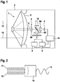
- Fig. 1 shows an optical device 1, which may in particular be part of a seeker head 2 of a missile.
- the optical device 1 comprises a reflecting telescope 9, which bundles optical radiations 14 from the surroundings of the optical device 1 and forwards them as a common beam path 8 to an optical system 6.
- the optical system 6 comprises a plurality of lenses 60 and a dichroic beam splitter 7 and is set up, the common beam path 8 to divide it to an optical sensor 3 and to a detection device 5.
- the optical sensor 3 is in particular an infrared sensor with a plurality of pixels, which can detect a target based on its optical signature. In particular, this signature represents the distribution of reflected or emitted radiation intensity on the target surface.
- the dichroic beam splitter 7 of the optical system 6 that a light source 4 introduces light into the common beam path 8, while the detection device 5 is able to detect the light of the light source 4 reflected by the target within the common beam path 8 , Therefore, it is possible with the optical device 1 according to the invention to use both the optical sensor 3 and the light source 4 and the detection device 5 together, since they always use a common beam path 8. Furthermore, it is possible to link the optical sensor 3 and the light source 4 together so that the light source 4 can be assigned a pixel of the optical sensor 3, so that the light source 4 illuminates exactly the area of the target imaged on the assigned pixel becomes.
- the assignment takes place via a retroreflector 16 which, via the dichroic beam splitter 7, reflects light of the light source 4 with a suitable wavelength onto the assigned pixel of the optical sensor 4. So a visual harmonization is possible.
- the optical harmonization of the light source 4 and the optical sensor 3 can preferably also be realized via additional light sources which in particular emit light which differs from the wavelength of the light of the light source. If the target to be illuminated is smaller than a pixel of the optical sensor 3, the light source 4 together with the detection device 5 is set up to determine that part of the pixel which images the target.
- the optical sensor 3, the light source 4 and the detection device 5 are connected to a control device 10 which performs a heterodyne detection.
- the heterodyne detection is in Fig. 2 shown schematically.
- the light to be detected by the detection device 5 is represented as a first signal 11 which is emitted by a mixer 15, preferably by a photodiode, with a second signal 12, preferably by the light source 4 or by an alternative light source. is mixed.
- the second signal 12 is preferably a predefined harmonic oscillator. This produces an intermediate signal 13 which can be processed by the control device 10. Since the second signal 12 has parameters known as a harmonic oscillator, the parameters of the first signal 11 can be easily deduced from the intermediate signal 13. In this way, a very accurate examination of the first signal 11 and thus of the reflected light is possible. Thus, a very high accuracy of the detection device 5 can be achieved.
- the seeker head 2 may be mounted in an exo-atmospheric interceptor rocket.
- the reflector telescope 9 may, in particular, have a focal length of approximately 600 mm and a diameter of 300 mm, the latter focusing the light emission in the infrared region of the target at a distance of, in particular, 600 km.
- the optical sensor 3 can detect the target already at this distance.
- a first guidance of the interceptor rocket is possible to the target, although this is still very inaccurate. From a distance of in particular 35 km, it is possible to illuminate the target by means of the reflector telescope 9 by means of the light source 4.
- the flight guidance of the interceptor rocket can be significantly improved by the seeker 2.
Description
- Die vorliegende Erfindung betrifft eine optische Vorrichtung, insbesondere zur Verwendung in Suchköpfen von Flugkörpern. Aus dem Stand der Technik sind passive Infrarotsuchköpfe für Flugkörper bekannt, die beispielsweise Raketen oder andere zu erfassende Zielobjekte anhand ihrer optischen Signatur erkennen können. Diese Signaturen repräsentieren die Verteilung von reflektierter oder emittierter Strahlungsintensität auf der Zieloberfläche. Sie ermöglichen eine Erkennung von Zielobjekten durch den Suchkopf und deren grobe Ortung im zweidimensionalen Winkelraum, liefern aber nur sehr ungenaue Informationen über den Bewegungszustand, die Entfernung und die dreidimensionale Gestalt dieser Zielobjekte.
- Insbesondere bei dynamischen Zielen könnte durch eine zeitlich hochaufgelöste Messung ihrer Distanz zum Suchkopf und ihre Relativbewegung in allen drei Freiheitsgraden die Treffergenauigkeit verbessert werden. Ebenso könnte durch die Erfassung der Tiefendimension des betreffenden Zielobjekts zusammen mit der Messung der Lagewinkelgeschwindigkeit, die Klassifizierung und die Ziel-Falschziel-Diskriminierung unterstützt werden.
- Aus dem Stand der Technik ist bekannt, dass passive Suchköpfe, um die zuvor genannten Vorteile zu erreichen, von Radarsensoren unterstützt werden. Die Radarsensoren helfen, die Informationen über Zielobjekte deutlich zu verbessern. Jedoch sind Radarsensoren aufgrund ihrer Größe und ihrer Architektur nur schwer in einen Suchkopf zu integrieren und werden daher beispielsweise oft als externe Sensoren unabhängig von dem Suchkopf bereitgestellt.
- Eine optische Vorrichtung gemäß dem Oberbegriff des Anspruchs 1 ist aus der
DE 32 19 533 A1 bekannt. Weiterhin ist aus derUS 2006/0231771 A1 ein LIDAR-System bekannt, mit dem Luftziele erfassbar sind. Schließlich offenbart dieDE 29 08 231 A1 ein Zielortungsverfahren, bei dem ein Laserstrahl das Ziel automatisch verfolgt und gleichzeitig als Freund-Feind-Erkennungssignal, Flugkörperleitstrahl und Zielmarkierer dient. - Des Weiteren beschreibt die Druckschrift
US 3 360 987 ein optisches System zur Bestimmung der Vibrationsfrequenz eines entfernten Gegenstands durch Aussenden eines kohärenten Lichtstrahls und Isolieren eines auf der durch Reflektion an einem vibrierenden Körper entstehenden Frequenzveränderung basierenden Signals. - Es ist Aufgabe der Erfindung, ein optisches System bereitzustellen, mit dem insbesondere ein Suchkopf betreibbar ist, wobei das optische System bei kostengünstiger Herstellung und Montage eine zuverlässige und ausführliche Bereitstellung von Zielinformationen ermöglicht.
- Gelöst wird die Aufgabe durch die Merkmale des Anspruchs 1. Dieser umfasst eine optische Vorrichtung, die insbesondere in einem Suchkopf eines Flugkörpers verwendbar ist. Die optische Vorrichtung umfasst zumindest einen optischen Sensor mit mehreren Pixeln, zumindest eine Lichtquelle, zumindest eine Detektionsvorrichtung und ein optisches System. Die Lichtquelle ist erfindungsgemäß derart eingerichtet, dass diese durch das optische System einen Gegenstand beleuchtet. Für die Beleuchtung mit der Lichtquelle ist vorgesehen, dass der Gegenstand durch das optische System mindestens auf einen Teilbereich eines vordefinierten Pixels des optischen Sensors abbildbar ist. Auf diese Weise sind Lichtquelle und optischer Sensor gekoppelt, was bedeutet, dass bei der optischen Vorrichtung von vornhinein bekannt ist, welcher Pixel des optischen Sensors denjenigen Bereich der Umgebung abbildet, der von der Lichtquelle beleuchtbar ist. Diese optische (Achs-)Harmonisierung ist bevorzugt durch einen Retroreflektor realisiert, über den die Lichtquelle den optischen Sensor, mit einer passenden Wellenlänge beleuchten kann. Sollte der zu beleuchtende Bereich kleiner als ein Pixel des optischen Sensors sein, so ist die Lichtquelle zusammen mit der Detektionsvorrichtung bevorzugt eingerichtet, denjenigen Teil des Pixels zu bestimmen, der den Bereich abbildet, d.h. den Ablagewinkel des Ziels mit Subpixelgenauigkeit zu bestimmen. Die Detektionsvorrichtung ist eingerichtet, das von der Lichtquelle ausgesandte und an dem Gegenstand reflektierte Licht zu detektieren. Insbesondere ist die Detektionsvorrichtung eingerichtet, das reflektierte Licht durch das optische System zu detektieren. Bevorzugt ist vorgesehen, dass mittels geeigneter Modulationsverfahren, wie beispielsweise der Frequenz, der Polarisation, der Phase oder der Amplitude, eine sehr genaue Messung der Entfernung und/oder des In-Range-Profils möglich ist. Weiterhin ermöglicht die optische Vorrichtung durch eine Dopplerauswertung, die Geschwindigkeit und/oder das Geschwindigkeitsprofil des Gegenstands zu ermitteln. Schließlich bildet die optische Vorrichtung bevorzugt ein sehr kompaktes Bauteil, das in einem Suchkopf eines Flugkörpers einsetzbar ist.
- Zusätzlich betrifft die Erfindung ein Verfahren zum Betreiben eines Suchkopfs eines Flugkörpers, wobei der Suchkopf zumindest einen optischen Sensor mit mehreren Pixeln, zumindest eine Lichtquelle und zumindest eine Detektionsvorrichtung umfasst. Weiterhin beinhaltet der Suchkopf ein optisches System, wobei die Lichtquelle eingerichtet ist, durch das optische System einen Gegenstand zu beleuchten, und wobei der Gegenstand durch das optische System zumindest auf einem vordefinierten Pixel des optischen Sensors abbildbar ist. Weiterhin ist die Detektionsvorrichtung eingerichtet, das von der Lichtquelle ausgesandte und an dem Gegenstand reflektierte Licht zu detektieren. Das erfindungsgemäße Verfahren umfasst die folgenden Schritte: Zunächst wird ein Ziel mittels des optischen Sensors oder bevorzugt mittels eines Infrarotsensors erfasst und eine erste Richtung, in der sich das Ziel relativ zu dem Flugkörper befindet, ausgegeben. Dies geschieht, sobald eine Entfernung zwischen Ziel und Flugkörper einen ersten vordefinierten Wert unterschreitet. Anschließend wird das Ziel mittels der Lichtquelle beleuchtet, sobald die Entfernung zwischen Ziel und Flugkörper einen zweiten vordefinierten Wert unterschreitet. Das von der Lichtquelle ausgesandte und von dem Ziel reflektierte Licht wird anschließend von der Detektionsvorrichtung detektiert. Schließlich wird, insbesondere mittels Laufzeitmessung und/oder Modulationsverfahren, eine Entfernung zwischen Ziel und Flugkörper bestimmt und/oder eine zweite Richtung bestimmt, in der sich das Ziel relativ zu dem Flugkörper befindet, und/oder, insbesondere mittels Dopplerverfahren, eine Relativgeschwindigkeit zwischen Ziel und Flugkörper bestimmt. Bevorzugt ist dabei vorgesehen, dass die erste Richtung lediglich eine grobe Richtung darstellt, in der sich das Ziel relativ zu dem Flugkörper befindet, während die zweite Richtung insbesondere eine genauere Richtungsangabe als die erste Richtung darstellt. So kann der optische Sensor bevorzugt erkennen, wo sich das Ziel relativ zu dem Flugkörper befindet, während mittels der Lichtquelle und der Detektionsvorrichtung eine genaue Messung innerhalb der von dem optischen Sensor vorgegebenen Richtung durchgeführt werden kann. Die zweite Richtung kann daher sehr schnell bestimmt werden, da die Lichtquelle und die Detektionsvorrichtung bereits im Wesentlichen darüber informiert sind, wo sich das Ziel befinden muss. In vorteilhafter Weise stehen durch die Beleuchtung des Ziels mittels der Lichtquelle und die Detektion des reflektierten Lichts präzise Informationen über die Relativgeschwindigkeit und/oder die Entfernung und/oder die Unterscheidung zwischen Ziel und Falsch-Ziel anhand von Dopplerprofilen und/oder In-Range-Profilen zur Verfügung. Somit kann durch das erfindungsgemäße Verfahren einem Flugkörper eine Vielzahl an Informationen zur Verfügung gestellt werden, so dass eine genaue Leitung des Flugkörpers zu dem Ziel möglich wird.
- Die Unteransprüche haben bevorzugte Weiterbildungen der Erfindung zum Inhalt.
- Bevorzugt ist vorgesehen, dass die Lichtquelle eine Laserquelle ist. Besonders bevorzugt ist die Laserquelle eine Infrarot-Laserquelle. Beispielsweise kann die Laserquelle kohärente kontinuierliche und/oder kohärente gepulste Strahlung mit hoher Spitzenleistung aussenden. Auf diese Weise kann die Reichweite, mit der die Detektionsvorrichtung reflektiertes Licht der Lichtquelle detektieren kann, gesteigert werden. Außerdem kann bevorzugt die Detektionsvorrichtung die Laufzeit der einzelnen Pulse bestimmen, um somit Entfernungsmessungen durchzuführen. Durch weitere Untersuchungen des reflektierten Lichts der Lichtquelle kann die Detektionsvorrichtung außerdem bevorzugt Daten liefern, die für die Bestimmung der Relativgeschwindigkeit des Gegenstands zu der optischen Vorrichtung nötig sind.
- Die optische Vorrichtung ist vorteilhafterweise derart ausgestaltet, dass das optische System einen dichroitischen Strahlteiler aufweist, der eingerichtet ist, optische Strahlungen zu dem optischen Sensor oder der Detektionsvorrichtung aus einem gemeinsamen Strahlengang zu trennen und/oder eingerichtet ist, das Licht der Lichtquelle in den gemeinsamen Strahlengang zu integrieren. Durch die Verwendung des optischen Systems zum Trennen und/oder Integrieren der optischen Strahlungen ist eine kompakte Bauweise der optischen Vorrichtung möglich. Außerdem ist es durch die Verwendung des Strahlteilers insbesondere möglich, mehreren Komponenten denselben Blickwinkel auf die Umgebung zu ermöglichen. Eine Kontrolle dieser Harmonisierung ist bevorzugt durch den zuvor beschriebenen Retroreflektor möglich.
- Vorteilhafterweise weist das optische System eine Linsenoptik und/oder eine Spiegeloptik auf. Das Spiegeloptik weist bevorzugt eine Brennweite von 600 mm und weist bevorzugt einen Durchmesser von 300 mm auf. Weiterhin ist bevorzugt vorgesehen, dass das Spiegelteleskop den zuvor beschriebenen gemeinsamen Strahlengang auf das optische System projiziert.
- In einer weiteren vorteilhaften Ausführungsform der Erfindung ist die Detektionsvorrichtung mit einer Steuervorrichtung verbunden. Die Steuervorrichtung ist bevorzugt eingerichtet, eine heterodyne und/oder besonders bevorzugt auch eine homodyne Detektion der empfangenen optischen Strahlung auszuführen. Die heterodyne Detektion erlaubt eine hohe Reichweite, mit der die Lichtquelle den Gegenstand beleuchten kann und mit der die Detektionsvorrichtung das von der Lichtquelle ausgesandte und von dem Gegenstand reflektierte Licht detektieren kann. Weiterhin erlaubt die heterodyne Detektion vorteilhaft das Ermitteln von Geschwindigkeitsinformationen und/oder Profilinformationen des Gegenstands. Zur Durchführung der heterodynen Detektion wird das von der Detektionsvorrichtung empfangene Licht in ein elektrisches Signal gewandelt, das bevorzugt an die Steuervorrichtung ausgegeben wird.
- Weiterhin ist bevorzugt vorgesehen, dass die Detektionsvorrichtung einen oder mehrere Pixel aufweist. Die Verwendung von mehreren Pixeln erlaubt die Auslegung als abbildenden Sensor, so dass die Detektionsvorrichtung mit jedem vorhandenen Pixel eine eigene Detektion des am Gegenstand reflektierten Lichts ausführen kann. Daher kann innerhalb des Detektionsbereichs der Detektionsvorrichtung zwischen unterschiedlichen Lichtintensitäten differenziert werden. Weiterhin sind mit den Pixeln bevorzugt einzelne Geschwindigkeiten und/oder Entfernungen und/oder Profile messbar. Alternativ oder zusätzlich kann die Detektionsvorrichtung zumindest einen Lichtleiter, insbesondere eine Glasfaser, aufweisen, so dass eine flexible räumliche Anordnung der Detektionsvorrichtung möglich ist.
- Die Erfindung betrifft weiterhin einen Suchkopf für einen Flugkörper, der eine optische Vorrichtung, wie zuvor beschrieben, umfasst. Die optische Vorrichtung kann vorteilhaft sehr kompakt aufgebaut werden, wodurch sich diese bevorzugt als Teil eines Suchkopfs eignet. Weiterhin ist durch die Lichtquelle und die Detektionsvorrichtung neben dem optischen Sensor eine weitere Messvorrichtung vorhanden, mit der der Suchkopf den Flugkörper optimal leiten kann.
- Bevorzugt wird das erfindungsgemäße Verfahren durchgeführt, indem die Detektionsvorrichtung das detektierte Licht als erstes Signal ausgibt, das mit einem als vordefinierten harmonischen Oszillator ausgelegten Signal gemischt wird. Auf diese Weise entsteht ein Zwischensignal, das bevorzugt dazu verwendet wird, eine Amplitude und/oder eine Frequenz und/oder eine Phase des ersten Signals zu bestimmen. Das Mischen erfolgt bevorzugt optisch, besonders bevorzugt mit dem Licht der Lichtquelle. Auf diese Weise wird eine homodyne Detektion realisiert. Alternativ ist besonders bevorzugt vorgesehen, dass das Mischen mit einer weiteren Lichtquelle erfolgt. In diesem Fall ist eine heterodyne Detektion realisiert. Das Mischen des ersten Signals mit dem zweiten Signal erlaubt aufgrund der besseren Auswertbarkeit des Zwischensignals, eine sehr genaue Auswertung des ersten Signals und damit eine sehr hohe Reichweite der Detektionsvorrichtung. Insbesondere wenn das erste Signal ein hochfrequentes und damit technisch schwer handzuhabendes Signal ist, bietet die Mischung mit dem zweiten Signal einen vorteilhaften Weg, die Parameter des ersten Signals zu bestimmen.
- Bevorzugt beträgt der erste vordefinierte Wert zumindest 600 km und/oder der zweite vordefinierte Wert zumindest 35 km. Somit kann der optische Sensor bereits sehr früh eine erste Richtung bestimmen, während die genauere Bestimmung der zweiten Richtung durch die Detektionsvorrichtung und die Lichtquelle erst später erfolgen kann, wenn sich die Entfernung zwischen Flugkörper und Ziel verringert hat.
- Die Erfindung wird nun anhand von Ausführungsbeispielen unter Berücksichtigung der beigefügten Zeichnungen weiter erläutert. Dabei zeigen:
- Fig. 1
- einen schematischen Aufbau der optischen Vorrichtung gemäß einem Ausführungsbeispiel der Erfindung, und
- Fig. 2
- eine schematische Darstellung der heterodynen Detektion, wie diese die optische Vorrichtung gemäß dem Ausführungsbeispiel der Erfindung verwendet.
-
Fig. 1 zeigt eine optische Vorrichtung 1, die insbesondere Teil eines Suchkopfes 2 eines Flugkörpers sein kann. Die optische Vorrichtung 1 umfasst ein Spiegelteleskop 9, das optische Strahlungen 14 aus der Umgebung der optischen Vorrichtung 1 bündelt und diese als einen gemeinsamen Strahlengang 8 an ein optisches System 6 weiterleitet. Das optische System 6 umfasst mehrere Linsen 60 sowie einen dichroitischen Strahlteiler 7 und ist eingerichtet, den gemeinsamen Strahlengang 8 aufzuteilen, um diesen zu einem optischen Sensor 3 und zu einer Detektionsvorrichtung 5 zu leiten. Der optische Sensor 3 ist insbesondere ein Infrarotsensor mit mehreren Pixeln, der ein Ziel anhand dessen optischer Signatur erkennen kann. Diese Signatur repräsentiert insbesondere die Verteilung von reflektierter oder emittierter Strahlungsintensität auf der Zieloberfläche. - Weiterhin ist es durch den dichroitischen Strahlteiler 7 des optischen Systems 6 möglich, dass eine Lichtquelle 4 Licht in den gemeinsamen Strahlengang 8 einleitet, während es der Detektionsvorrichtung 5 möglich ist, das von dem Ziel reflektierte Licht der Lichtquelle 4 innerhalb des gemeinsamen Strahlengangs 8 zu detektieren. Daher ist es mit der erfindungsgemäßen optischen Vorrichtung 1 möglich, sowohl den optischen Sensor 3 als auch die Lichtquelle 4 und die Detektionsvorrichtung 5 gemeinsam zu verwenden, da diese stets einen gemeinsamen Strahlengang 8 verwenden. Weiterhin ist es möglich, den optischen Sensor 3 und die Lichtquelle 4 derart miteinander zu verknüpfen, dass der Lichtquelle 4 ein Pixel des optischen Sensors 3 zugewiesen werden kann, so dass die Lichtquelle 4 genau den Bereich des Ziels beleuchtet, der auf dem zugewiesenen Pixel abgebildet wird. Die Zuweisung erfolgt über einen Retroreflektor 16, der über den dichroitischen Strahlteiler 7 Licht der Lichtquelle 4 mit einer geeigneten Wellenlänge auf den zugewiesenen Pixel des optischen Sensors 4 reflektiert. So ist eine optische Harmonisierung möglich. Die optische Harmonisierung von Lichtquelle 4 und optischem Sensor 3 kann bevorzugt auch über zusätzliche Lichtquellen realisiert sein, die insbesondere Licht aussenden, das sich von der Wellenlänge des Lichts der Lichtquelle unterscheidet. Sollte das zu beleuchtende Ziel kleiner als ein Pixel des optischen Sensors 3 sein, so ist die Lichtquelle 4 zusammen mit der Detektionsvorrichtung 5 eingerichtet, denjenigen Teil des Pixels zu bestimmen, der das Ziel abbildet.
- Der optische Sensor 3, die Lichtquelle 4 und die Detektionsvorrichtung 5 sind mit einer Steuervorrichtung 10 verbunden, die eine heterodyne Detektion durchführt. Die heterodyne Detektion ist in
Fig. 2 schematisch dargestellt. Das von der Detektionsvorrichtung 5 zu detektierende Licht ist als erstes Signal 11 repräsentiert, das von einem Mischer 15, bevorzugt von einer Photodiode, mit einem zweiten Signal 12, bevorzugt von der Lichtquelle 4 oder von einer alternativen Lichtquelle ausgesandt wird, gemischt wird. Das zweite Signal 12 ist bevorzugt ein vordefinierter harmonischer Oszillator. So entsteht ein Zwischensignal 13, das von der Steuervorrichtung 10 verarbeitbar ist. Da das zweite Signal 12 als harmonischer Oszillator bekannte Parameter aufweist, kann aus dem Zwischensignal 13 sehr einfach auf die Parameter des ersten Signals 11 geschlossen werden. Auf diese Weise ist eine sehr genaue Untersuchung des ersten Signals 11 und damit des reflektierten Lichts möglich. So ist eine sehr hohe Genauigkeit der Detektionsvorrichtung 5 erreichbar. - Beispielsweise kann der Suchkopf 2 in einer exo-atmosphärischen Abfangrakete angebracht sein. Das Spiegelteleskop 9 kann insbesondere eine Brennweite von ca. 600 mm und einen Durchmesser von 300 mm aufweisen, wobei dieses ab einer Entfernung von insbesondere 600 km die Lichtemission im infraroten Bereich des Ziels fokussiert. Somit kann bereits ab dieser Entfernung der optische Sensor 3 das Ziel erfassen. Damit ist eine erste Führung der Abfangrakete zu dem Ziel möglich, wenngleich diese noch sehr ungenau ist. Ab einer Entfernung von insbesondere 35 km ist es möglich, durch das Spiegelteleskop 9 das Ziel mittels der Lichtquelle 4 zu beleuchten. Durch die heterodyne Detektion des von der Detektionsvorrichtung 5 empfangenen Lichts, das ausgehend von der Lichtquelle 4 an dem Ziel reflektiert wurde, ist es nun möglich, zusätzliche präzise Informationen über Geschwindigkeit und/oder Entfernung des Ziels zu erlangen. Damit kann die Flugführung der Abfangrakete durch den Suchkopf 2 deutlich verbessert werden.
-
- 1
- Optische Vorrichtung
- 2
- Suchkopf
- 3
- Optischer Sensor
- 4
- Lichtquelle
- 5
- Detektionsvorrichtung
- 6
- Optisches System
- 60
- Linse
- 7
- Dichroitischer Strahlteiler
- 8
- Gemeinsamer Strahlengang
- 9
- Spiegelteleskop
- 10
- Steuervorrichtung
- 11
- Erstes Signal
- 12
- Zweites Signal
- 13
- Zwischensignal
- 14
- Optische Strahlung
- 15
- Mischer
- 16
- Retroreflektor
Claims (11)
- Optische Vorrichtung (1), insbesondere für einen Suchkopf (2) eines Flugkörpers, umfassend- zumindest eine Lichtquelle (4),- zumindest eine Detektionsvorrichtung (5), wobei die Detektionsvorrichtung (5) eingerichtet ist, das von der Lichtquelle (4) ausgesandte und an dem Gegenstand reflektierte Licht zu detektieren,gekennzeichnet durch- zumindest einen optischen Sensor (3) mit mehreren Pixeln, und- ein optisches System (6), das einen dichroitischen Strahlteiler (7) aufweist, der eingerichtet ist, optische Strahlungen aus der Umgebung der optischen Vorrichtung (1) zu dem optischen Sensor (3) oder der Detektionsvorrichtung (5) aus einem gemeinsamen Strahlengang (8) zu trennen und das Licht der Lichtquelle (4) in den gemeinsamen Strahlengang (8) zu integrieren, und das einen Retroreflektor (16) aufweist, über den der optische Sensor (3) von der Lichtquelle (4) beleuchtbar ist,- wobei die Lichtquelle (4) eingerichtet ist, durch das optische System (6) einen Gegenstand zu beleuchten, der durch das optische System (6) mindestens auf einem Teilbereich eines vordefinierten Pixels des optischen Sensors (3) abbildbar ist.
- Optische Vorrichtung nach Anspruch 1, dadurch gekennzeichnet, dass die Lichtquelle (4) eine Laserquelle, bevorzugt eine Infrarot-Laserquelle, ist.
- Optische Vorrichtung nach einem der vorhergehenden Ansprüche, dadurch gekennzeichnet, dass das optische System (6) eine Linsenoptik und/oder ein Spiegelteleskop (9) aufweist.
- Optische Vorrichtung nach einem der vorhergehenden Ansprüche, dadurch gekennzeichnet, dass die Detektionsvorrichtung (5) mit einer Steuervorrichtung (10) verbunden ist, wobei die Steuervorrichtung eingerichtet ist, eine heterodyne Detektion und/oder eine homodyne Detektion der empfangenen optischen Strahlung auszuführen.
- Optische Vorrichtung nach einem der vorhergehenden Ansprüche, wobei die Detektionsvorrichtung (5) einen oder mehrere Pixel und/oder zumindest einen Lichtleiter, aufweist.
- Suchkopf (2) für einen Flugkörper, umfassend eine optische Vorrichtung (1) nach einem der vorhergehenden Ansprüche.
- Verfahren zum Betreiben eines Suchkopfes (2) eines Flugkörpers, wobei der Suchkopf (2)- zumindest eine Lichtquelle (4),- zumindest eine Detektionsvorrichtung (5), weiche dazu eingerichtet ist, das von der Lichtquelle (4) ausgesandte und an dem Gegenstand reflektierte Licht zu detektieren,- zumindest einen optischen Sensor (3) mit mehreren Pixeln, und ein optisches System (6), das einen dichroitischen Strahlteiler (7) aufweist, der eingerichtet ist, optische Strahlungen aus der Umgebung des Suchkopfes (2) zu dem optischen Sensor (3) oder der Detektionsvorrichtung (5) aus einem gemeinsamen Strahlengang (8) zu trennen und das Licht der Lichtquelle (4) in den gemeinsamen Strahlengang (8) zu integrieren, und das einen Retroreflektor (16) aufweist, über den der optische Sensor (3) von der Lichtquelle (4) beleuchtbar ist, umfasst, und- wobei die Lichtquelle (4) eingerichtet ist, durch das optische System (6) einen Gegenstand zu beleuchten, der durch das optische System (6) mindestens auf einem Teilbereich eines vordefinierten Pixels des optischen Sensors (3) abbildbar ist, gekennzeichnet durch die folgenden Schritte:- Erfassen eines Ziels mittels des optischen Sensors (3) und ausgeben einer ersten Richtung, in der sich das Ziel relativ zu dem Flugkörper befindet, sobald die Entfernung zwischen Ziel und Flugkörper einen ersten vordefinierten Wert unterschreitet,- Beleuchten des Ziels mittels der Lichtquelle (4), sobald die Entfernung zwischen Ziel und Flugkörper einen zweiten vordefinierten Wert unterschreitet, und- Detektieren des von der Lichtquelle (4) ausgesandten und von dem Ziel reflektierten Lichts durch die Detektionsvorrichtung (5) und Bestimmen mindestens einer der folgenden Größen:∘ eine Entfernung zwischen Ziel und Flugkörper;∘ eine zweite Richtung, in der sich das Ziel relativ zu dem Flugkörper befindet;∘ eine Relativgeschwindigkeit zwischen Ziel und Flugkörper.
- Verfahren nach Anspruch 7, dadurch gekennzeichnet, dass das Bestimmen der Entfernung durch Modulation und/oder Laufzeitmessung erfolgt.
- Verfahren nach Anspruch 7 oder 8, dadurch gekennzeichnet, dass das Bestimmen der Geschwindigkeit mittels Dopplerverfahren erfolgt.
- Verfahren nach einem der Ansprüche 7 bis 9, dadurch gekennzeichnet, dass das von der Detektionsvorrichtung detektierte Licht als erstes Signal (11) angesehen wird, das mit einem als vordefinierter harmonischer Oszillator ausgelegten zweiten Signal (12), bevorzugt optisch, gemischt wird, so dass ein Zwischensignal (13) entsteht, wobei aus dem Zwischensignat (13) eine Amplitude und/oder eine Frequenz und/oder eine Phase des ersten Signals (11) bestimmt wird.
- Verfahren nach einem der Ansprüche 7 bis 10, dadurch gekennzeichnet, dass der erste vordefinierte Wert zumindest 600 Kilometer beträgt und/oder der zweite vordefinierte Wert zumindest 35 Kilometer beträgt.
Applications Claiming Priority (1)
| Application Number | Priority Date | Filing Date | Title |
|---|---|---|---|
| DE102013003660.7A DE102013003660A1 (de) | 2013-03-02 | 2013-03-02 | Optische Vorrichtung |
Publications (2)
| Publication Number | Publication Date |
|---|---|
| EP2772719A1 EP2772719A1 (de) | 2014-09-03 |
| EP2772719B1 true EP2772719B1 (de) | 2018-09-19 |
Family
ID=50184713
Family Applications (1)
| Application Number | Title | Priority Date | Filing Date |
|---|---|---|---|
| EP14000634.7A Active EP2772719B1 (de) | 2013-03-02 | 2014-02-24 | Optische Vorrichtung |
Country Status (5)
| Country | Link |
|---|---|
| US (1) | US9194658B2 (de) |
| EP (1) | EP2772719B1 (de) |
| DE (1) | DE102013003660A1 (de) |
| ES (1) | ES2693787T3 (de) |
| IN (1) | IN2014MU00635A (de) |
Families Citing this family (2)
| Publication number | Priority date | Publication date | Assignee | Title |
|---|---|---|---|---|
| EP3948331A1 (de) * | 2019-03-25 | 2022-02-09 | Nikon Metrology NV | Laserradar |
| DE102021113459A1 (de) | 2021-05-25 | 2022-12-01 | Rheinmetall Electronics Gmbh | Simulator und system zur simulation eines lenkflugkörpersystems |
Citations (1)
| Publication number | Priority date | Publication date | Assignee | Title |
|---|---|---|---|---|
| US3360987A (en) * | 1964-07-03 | 1968-01-02 | Gen Precision Inc | Optical radar system |
Family Cites Families (19)
| Publication number | Priority date | Publication date | Assignee | Title |
|---|---|---|---|---|
| US6198564B1 (en) * | 1973-01-29 | 2001-03-06 | Raytheon Company | Optical scanning system |
| US4105174A (en) * | 1973-06-08 | 1978-08-08 | Ab Bofors | Device for receiving or transmitting radiation |
| US6078606A (en) * | 1975-03-17 | 2000-06-20 | Lockheed Martin Corporation | Multi-color, multi-pulse laser |
| US4024392A (en) * | 1976-03-08 | 1977-05-17 | The United States Of America As Represented By The Secretary Of The Navy | Gimballed active optical system |
| DE2908231A1 (de) * | 1979-03-02 | 1980-09-04 | Messerschmitt Boelkow Blohm | Co tief 2 -laser-zielortungs- und flugkoerperlenkverfahren |
| SE423451B (sv) * | 1980-09-15 | 1982-05-03 | Philips Svenska Ab | Sett for samarbete mellan projektiler och malfoljande projektil for genomforande av settet vid bekempning av mal |
| DE3219533A1 (de) * | 1982-05-25 | 1983-12-08 | Messerschmitt-Bölkow-Blohm GmbH, 8000 München | Einrichtung zur detektion von bewegten zielen |
| US4497065A (en) * | 1982-07-12 | 1985-01-29 | Westinghouse Electric Corp. | Target recognition system enhanced by active signature measurements |
| US4733609A (en) * | 1987-04-03 | 1988-03-29 | Digital Signal Corporation | Laser proximity sensor |
| US4894724A (en) * | 1987-12-23 | 1990-01-16 | Hughes Aircraft Company | System and method for producing a flicker-free video image |
| DE4007712A1 (de) * | 1990-03-10 | 1991-09-12 | Tzn Forschung & Entwicklung | Geschoss mit einem bugseitig angeordneten ir-suchsystem |
| US6145784A (en) * | 1997-08-27 | 2000-11-14 | Trw Inc. | Shared aperture dichroic active tracker with background subtraction |
| US6262800B1 (en) * | 1999-03-05 | 2001-07-17 | Lockheed Martin Corporation | Dual mode semi-active laser/laser radar seeker |
| US6410897B1 (en) * | 2000-09-27 | 2002-06-25 | Raytheon Company | Method and apparatus for aircraft protection against missile threats |
| US6943873B2 (en) * | 2001-07-17 | 2005-09-13 | Bae Systems Integrated Defense Solutions Inc. | Fiber optical laser detection and ranging system |
| WO2003067276A2 (en) * | 2002-02-04 | 2003-08-14 | Bae Systems Information And Electronic Systems Integration Inc. | Reentry vehicle interceptor with ir and variable fov laser radar |
| US7221436B1 (en) * | 2004-08-05 | 2007-05-22 | Itt Manufacturing Enterprises Inc. | System and method for optimization-based sensor steering and tracking |
| US7741618B2 (en) * | 2004-11-19 | 2010-06-22 | Science & Engineering Services, Inc. | Enhanced portable digital lidar system |
| DE102007014256B4 (de) | 2007-03-24 | 2013-08-08 | Mbda Deutschland Gmbh | Zielerfassungsverfahren und -Vorrichtung mit kohärentem Empfang |
-
2013
- 2013-03-02 DE DE102013003660.7A patent/DE102013003660A1/de not_active Withdrawn
-
2014
- 2014-02-24 EP EP14000634.7A patent/EP2772719B1/de active Active
- 2014-02-24 ES ES14000634.7T patent/ES2693787T3/es active Active
- 2014-02-24 IN IN635MU2014 patent/IN2014MU00635A/en unknown
- 2014-02-28 US US14/193,817 patent/US9194658B2/en not_active Expired - Fee Related
Patent Citations (1)
| Publication number | Priority date | Publication date | Assignee | Title |
|---|---|---|---|---|
| US3360987A (en) * | 1964-07-03 | 1968-01-02 | Gen Precision Inc | Optical radar system |
Also Published As
| Publication number | Publication date |
|---|---|
| US9194658B2 (en) | 2015-11-24 |
| US20140246536A1 (en) | 2014-09-04 |
| EP2772719A1 (de) | 2014-09-03 |
| DE102013003660A1 (de) | 2014-09-04 |
| ES2693787T3 (es) | 2018-12-13 |
| IN2014MU00635A (de) | 2015-10-23 |
Similar Documents
| Publication | Publication Date | Title |
|---|---|---|
| EP3220163B1 (de) | Lasertracker mit zwei messfunktionalitäten | |
| EP2810020B1 (de) | Vermessungsgerät mit scanfunktionalität und einzelpunktmessmodus | |
| EP0987564B1 (de) | Vorrichtung zur optischen Distanzmessung | |
| EP2124069B1 (de) | Omnidirektionales Lidar System | |
| EP0842395B1 (de) | Verfahren und vorrichtung zur schnellen erfassung der lage einer zielmarke | |
| DE102004037137B4 (de) | Verfahren und Vorrichtung zur Entfernungsmessung | |
| EP3165876A2 (de) | Opto-elektronisches vermessungsgerät | |
| EP2801841A1 (de) | Lasertracker mit einer Zielerfassungseinheit für eine Zielverfolgung und eine Orientierungserkennung | |
| DE4445464A1 (de) | Abtastvorrichtung | |
| WO2010063545A1 (de) | Positionsbestimmungsverfahren und geodätisches vermessungssystem | |
| DE102018222629A1 (de) | Verfahren und Vorrichtung zur Bestimmung von mindestens einer räumlichen Position und Orientierung mindestens eines Objekts | |
| EP3339803B1 (de) | Koordinatenmessgerät mit automatischer zielobjekterkennung | |
| DE112012007096T5 (de) | Trackereinheit und Verfahren in einer Trackereinheit | |
| EP3579015A1 (de) | Verfahren und vorrichtung zur detektion eines objekts mittels breitbandiger laserpulse | |
| DE102017200691B4 (de) | Projektionsvorrichtung und Verfahren zum Abtasten eines Raumwinkelbereichs mit einem Laserstrahl | |
| EP1248120B1 (de) | Dual-Mode Suchkopf | |
| EP2772719B1 (de) | Optische Vorrichtung | |
| DE102007045334A1 (de) | Messsystem | |
| DE2850743C3 (de) | Verfahren und Vorrichtung zur Messung der Abweichung des Sendestrahls von der optischen Achse des Empfangsteleskops bei einem Lidargerät | |
| DE102017209259A1 (de) | Lidarsystem | |
| DE102019216195A1 (de) | Vorrichtung und Verfahren zur Bestimmung einer räumlichen Position und Orientierung | |
| WO2015003833A1 (de) | Bestimmung eines abstands und eines winkels in bezug auf eine ebene mittels mehrerer entfernungsmessungen | |
| DE102010003411A1 (de) | Lichtlaufzeit-Kamera | |
| DE102016006776A1 (de) | Vorrichtung und Verfahren zur eindeutigen Abstandsmessung mit moduliertem LIDAR | |
| DE3812984C1 (en) | Continuously locating and guiding missile or aircraft - measuring laser radiation returned from on-board reflector using transceiver goniometer unit |
Legal Events
| Date | Code | Title | Description |
|---|---|---|---|
| PUAI | Public reference made under article 153(3) epc to a published international application that has entered the european phase |
Free format text: ORIGINAL CODE: 0009012 |
|
| 17P | Request for examination filed |
Effective date: 20140224 |
|
| AK | Designated contracting states |
Kind code of ref document: A1 Designated state(s): AL AT BE BG CH CY CZ DE DK EE ES FI FR GB GR HR HU IE IS IT LI LT LU LV MC MK MT NL NO PL PT RO RS SE SI SK SM TR |
|
| AX | Request for extension of the european patent |
Extension state: BA ME |
|
| R17P | Request for examination filed (corrected) |
Effective date: 20150211 |
|
| 17Q | First examination report despatched |
Effective date: 20160802 |
|
| STAA | Information on the status of an ep patent application or granted ep patent |
Free format text: STATUS: EXAMINATION IS IN PROGRESS |
|
| REG | Reference to a national code |
Ref country code: DE Ref legal event code: R079 Ref document number: 502014009491 Country of ref document: DE Free format text: PREVIOUS MAIN CLASS: F41H0013000000 Ipc: G01S0017320000 |
|
| GRAP | Despatch of communication of intention to grant a patent |
Free format text: ORIGINAL CODE: EPIDOSNIGR1 |
|
| STAA | Information on the status of an ep patent application or granted ep patent |
Free format text: STATUS: GRANT OF PATENT IS INTENDED |
|
| RIC1 | Information provided on ipc code assigned before grant |
Ipc: G01S 17/02 20060101ALI20180328BHEP Ipc: F41G 7/22 20060101ALI20180328BHEP Ipc: G01S 17/32 20060101AFI20180328BHEP Ipc: G01S 7/481 20060101ALI20180328BHEP Ipc: G01J 5/10 20060101ALI20180328BHEP Ipc: G01S 17/42 20060101ALI20180328BHEP Ipc: F41G 7/00 20060101ALI20180328BHEP Ipc: G01S 17/58 20060101ALI20180328BHEP |
|
| INTG | Intention to grant announced |
Effective date: 20180430 |
|
| RIN1 | Information on inventor provided before grant (corrected) |
Inventor name: ZOZ, JUERGEN Inventor name: FENDT, ALFRED Inventor name: SENFT, CHRISTOPH |
|
| GRAS | Grant fee paid |
Free format text: ORIGINAL CODE: EPIDOSNIGR3 |
|
| GRAA | (expected) grant |
Free format text: ORIGINAL CODE: 0009210 |
|
| STAA | Information on the status of an ep patent application or granted ep patent |
Free format text: STATUS: THE PATENT HAS BEEN GRANTED |
|
| AK | Designated contracting states |
Kind code of ref document: B1 Designated state(s): AL AT BE BG CH CY CZ DE DK EE ES FI FR GB GR HR HU IE IS IT LI LT LU LV MC MK MT NL NO PL PT RO RS SE SI SK SM TR |
|
| REG | Reference to a national code |
Ref country code: GB Ref legal event code: FG4D Free format text: NOT ENGLISH |
|
| REG | Reference to a national code |
Ref country code: CH Ref legal event code: EP |
|
| REG | Reference to a national code |
Ref country code: AT Ref legal event code: REF Ref document number: 1043892 Country of ref document: AT Kind code of ref document: T Effective date: 20181015 |
|
| REG | Reference to a national code |
Ref country code: IE Ref legal event code: FG4D Free format text: LANGUAGE OF EP DOCUMENT: GERMAN |
|
| REG | Reference to a national code |
Ref country code: DE Ref legal event code: R096 Ref document number: 502014009491 Country of ref document: DE |
|
| REG | Reference to a national code |
Ref country code: ES Ref legal event code: FG2A Ref document number: 2693787 Country of ref document: ES Kind code of ref document: T3 Effective date: 20181213 |
|
| REG | Reference to a national code |
Ref country code: NL Ref legal event code: MP Effective date: 20180919 |
|
| PG25 | Lapsed in a contracting state [announced via postgrant information from national office to epo] |
Ref country code: GR Free format text: LAPSE BECAUSE OF FAILURE TO SUBMIT A TRANSLATION OF THE DESCRIPTION OR TO PAY THE FEE WITHIN THE PRESCRIBED TIME-LIMIT Effective date: 20181220 Ref country code: FI Free format text: LAPSE BECAUSE OF FAILURE TO SUBMIT A TRANSLATION OF THE DESCRIPTION OR TO PAY THE FEE WITHIN THE PRESCRIBED TIME-LIMIT Effective date: 20180919 Ref country code: LT Free format text: LAPSE BECAUSE OF FAILURE TO SUBMIT A TRANSLATION OF THE DESCRIPTION OR TO PAY THE FEE WITHIN THE PRESCRIBED TIME-LIMIT Effective date: 20180919 Ref country code: BG Free format text: LAPSE BECAUSE OF FAILURE TO SUBMIT A TRANSLATION OF THE DESCRIPTION OR TO PAY THE FEE WITHIN THE PRESCRIBED TIME-LIMIT Effective date: 20181219 Ref country code: NO Free format text: LAPSE BECAUSE OF FAILURE TO SUBMIT A TRANSLATION OF THE DESCRIPTION OR TO PAY THE FEE WITHIN THE PRESCRIBED TIME-LIMIT Effective date: 20181219 Ref country code: RS Free format text: LAPSE BECAUSE OF FAILURE TO SUBMIT A TRANSLATION OF THE DESCRIPTION OR TO PAY THE FEE WITHIN THE PRESCRIBED TIME-LIMIT Effective date: 20180919 Ref country code: SE Free format text: LAPSE BECAUSE OF FAILURE TO SUBMIT A TRANSLATION OF THE DESCRIPTION OR TO PAY THE FEE WITHIN THE PRESCRIBED TIME-LIMIT Effective date: 20180919 |
|
| REG | Reference to a national code |
Ref country code: LT Ref legal event code: MG4D |
|
| PG25 | Lapsed in a contracting state [announced via postgrant information from national office to epo] |
Ref country code: AL Free format text: LAPSE BECAUSE OF FAILURE TO SUBMIT A TRANSLATION OF THE DESCRIPTION OR TO PAY THE FEE WITHIN THE PRESCRIBED TIME-LIMIT Effective date: 20180919 Ref country code: LV Free format text: LAPSE BECAUSE OF FAILURE TO SUBMIT A TRANSLATION OF THE DESCRIPTION OR TO PAY THE FEE WITHIN THE PRESCRIBED TIME-LIMIT Effective date: 20180919 Ref country code: HR Free format text: LAPSE BECAUSE OF FAILURE TO SUBMIT A TRANSLATION OF THE DESCRIPTION OR TO PAY THE FEE WITHIN THE PRESCRIBED TIME-LIMIT Effective date: 20180919 |
|
| PG25 | Lapsed in a contracting state [announced via postgrant information from national office to epo] |
Ref country code: PL Free format text: LAPSE BECAUSE OF FAILURE TO SUBMIT A TRANSLATION OF THE DESCRIPTION OR TO PAY THE FEE WITHIN THE PRESCRIBED TIME-LIMIT Effective date: 20180919 Ref country code: EE Free format text: LAPSE BECAUSE OF FAILURE TO SUBMIT A TRANSLATION OF THE DESCRIPTION OR TO PAY THE FEE WITHIN THE PRESCRIBED TIME-LIMIT Effective date: 20180919 Ref country code: IS Free format text: LAPSE BECAUSE OF FAILURE TO SUBMIT A TRANSLATION OF THE DESCRIPTION OR TO PAY THE FEE WITHIN THE PRESCRIBED TIME-LIMIT Effective date: 20190119 Ref country code: RO Free format text: LAPSE BECAUSE OF FAILURE TO SUBMIT A TRANSLATION OF THE DESCRIPTION OR TO PAY THE FEE WITHIN THE PRESCRIBED TIME-LIMIT Effective date: 20180919 Ref country code: CZ Free format text: LAPSE BECAUSE OF FAILURE TO SUBMIT A TRANSLATION OF THE DESCRIPTION OR TO PAY THE FEE WITHIN THE PRESCRIBED TIME-LIMIT Effective date: 20180919 Ref country code: NL Free format text: LAPSE BECAUSE OF FAILURE TO SUBMIT A TRANSLATION OF THE DESCRIPTION OR TO PAY THE FEE WITHIN THE PRESCRIBED TIME-LIMIT Effective date: 20180919 |
|
| PG25 | Lapsed in a contracting state [announced via postgrant information from national office to epo] |
Ref country code: SK Free format text: LAPSE BECAUSE OF FAILURE TO SUBMIT A TRANSLATION OF THE DESCRIPTION OR TO PAY THE FEE WITHIN THE PRESCRIBED TIME-LIMIT Effective date: 20180919 Ref country code: PT Free format text: LAPSE BECAUSE OF FAILURE TO SUBMIT A TRANSLATION OF THE DESCRIPTION OR TO PAY THE FEE WITHIN THE PRESCRIBED TIME-LIMIT Effective date: 20190119 Ref country code: SM Free format text: LAPSE BECAUSE OF FAILURE TO SUBMIT A TRANSLATION OF THE DESCRIPTION OR TO PAY THE FEE WITHIN THE PRESCRIBED TIME-LIMIT Effective date: 20180919 |
|
| REG | Reference to a national code |
Ref country code: DE Ref legal event code: R097 Ref document number: 502014009491 Country of ref document: DE |
|
| PLBE | No opposition filed within time limit |
Free format text: ORIGINAL CODE: 0009261 |
|
| STAA | Information on the status of an ep patent application or granted ep patent |
Free format text: STATUS: NO OPPOSITION FILED WITHIN TIME LIMIT |
|
| PG25 | Lapsed in a contracting state [announced via postgrant information from national office to epo] |
Ref country code: DK Free format text: LAPSE BECAUSE OF FAILURE TO SUBMIT A TRANSLATION OF THE DESCRIPTION OR TO PAY THE FEE WITHIN THE PRESCRIBED TIME-LIMIT Effective date: 20180919 |
|
| 26N | No opposition filed |
Effective date: 20190620 |
|
| REG | Reference to a national code |
Ref country code: CH Ref legal event code: PL |
|
| PG25 | Lapsed in a contracting state [announced via postgrant information from national office to epo] |
Ref country code: SI Free format text: LAPSE BECAUSE OF FAILURE TO SUBMIT A TRANSLATION OF THE DESCRIPTION OR TO PAY THE FEE WITHIN THE PRESCRIBED TIME-LIMIT Effective date: 20180919 Ref country code: LU Free format text: LAPSE BECAUSE OF NON-PAYMENT OF DUE FEES Effective date: 20190224 Ref country code: MC Free format text: LAPSE BECAUSE OF FAILURE TO SUBMIT A TRANSLATION OF THE DESCRIPTION OR TO PAY THE FEE WITHIN THE PRESCRIBED TIME-LIMIT Effective date: 20180919 |
|
| REG | Reference to a national code |
Ref country code: BE Ref legal event code: MM Effective date: 20190228 |
|
| REG | Reference to a national code |
Ref country code: IE Ref legal event code: MM4A |
|
| PG25 | Lapsed in a contracting state [announced via postgrant information from national office to epo] |
Ref country code: LI Free format text: LAPSE BECAUSE OF NON-PAYMENT OF DUE FEES Effective date: 20190228 Ref country code: CH Free format text: LAPSE BECAUSE OF NON-PAYMENT OF DUE FEES Effective date: 20190228 |
|
| PG25 | Lapsed in a contracting state [announced via postgrant information from national office to epo] |
Ref country code: IE Free format text: LAPSE BECAUSE OF NON-PAYMENT OF DUE FEES Effective date: 20190224 |
|
| PG25 | Lapsed in a contracting state [announced via postgrant information from national office to epo] |
Ref country code: BE Free format text: LAPSE BECAUSE OF NON-PAYMENT OF DUE FEES Effective date: 20190228 |
|
| PG25 | Lapsed in a contracting state [announced via postgrant information from national office to epo] |
Ref country code: TR Free format text: LAPSE BECAUSE OF FAILURE TO SUBMIT A TRANSLATION OF THE DESCRIPTION OR TO PAY THE FEE WITHIN THE PRESCRIBED TIME-LIMIT Effective date: 20180919 |
|
| REG | Reference to a national code |
Ref country code: AT Ref legal event code: MM01 Ref document number: 1043892 Country of ref document: AT Kind code of ref document: T Effective date: 20190224 |
|
| PG25 | Lapsed in a contracting state [announced via postgrant information from national office to epo] |
Ref country code: AT Free format text: LAPSE BECAUSE OF NON-PAYMENT OF DUE FEES Effective date: 20190224 |
|
| PG25 | Lapsed in a contracting state [announced via postgrant information from national office to epo] |
Ref country code: MT Free format text: LAPSE BECAUSE OF FAILURE TO SUBMIT A TRANSLATION OF THE DESCRIPTION OR TO PAY THE FEE WITHIN THE PRESCRIBED TIME-LIMIT Effective date: 20180919 |
|
| PG25 | Lapsed in a contracting state [announced via postgrant information from national office to epo] |
Ref country code: CY Free format text: LAPSE BECAUSE OF FAILURE TO SUBMIT A TRANSLATION OF THE DESCRIPTION OR TO PAY THE FEE WITHIN THE PRESCRIBED TIME-LIMIT Effective date: 20180919 |
|
| PG25 | Lapsed in a contracting state [announced via postgrant information from national office to epo] |
Ref country code: HU Free format text: LAPSE BECAUSE OF FAILURE TO SUBMIT A TRANSLATION OF THE DESCRIPTION OR TO PAY THE FEE WITHIN THE PRESCRIBED TIME-LIMIT; INVALID AB INITIO Effective date: 20140224 |
|
| PG25 | Lapsed in a contracting state [announced via postgrant information from national office to epo] |
Ref country code: MK Free format text: LAPSE BECAUSE OF FAILURE TO SUBMIT A TRANSLATION OF THE DESCRIPTION OR TO PAY THE FEE WITHIN THE PRESCRIBED TIME-LIMIT Effective date: 20180919 |
|
| PGFP | Annual fee paid to national office [announced via postgrant information from national office to epo] |
Ref country code: FR Payment date: 20230221 Year of fee payment: 10 |
|
| PGFP | Annual fee paid to national office [announced via postgrant information from national office to epo] |
Ref country code: IT Payment date: 20230223 Year of fee payment: 10 Ref country code: GB Payment date: 20230220 Year of fee payment: 10 Ref country code: DE Payment date: 20230228 Year of fee payment: 10 |
|
| P01 | Opt-out of the competence of the unified patent court (upc) registered |
Effective date: 20230509 |
|
| PGFP | Annual fee paid to national office [announced via postgrant information from national office to epo] |
Ref country code: ES Payment date: 20230426 Year of fee payment: 10 |