EP2772717A1 - Flow channel member, heat exchanger using same, semiconductor device, and device for manufacturing semiconductor - Google Patents
Flow channel member, heat exchanger using same, semiconductor device, and device for manufacturing semiconductor Download PDFInfo
- Publication number
- EP2772717A1 EP2772717A1 EP12843158.2A EP12843158A EP2772717A1 EP 2772717 A1 EP2772717 A1 EP 2772717A1 EP 12843158 A EP12843158 A EP 12843158A EP 2772717 A1 EP2772717 A1 EP 2772717A1
- Authority
- EP
- European Patent Office
- Prior art keywords
- channel
- wall part
- fluid
- channel member
- bottom plate
- Prior art date
- Legal status (The legal status is an assumption and is not a legal conclusion. Google has not performed a legal analysis and makes no representation as to the accuracy of the status listed.)
- Granted
Links
Images





Classifications
-
- F—MECHANICAL ENGINEERING; LIGHTING; HEATING; WEAPONS; BLASTING
- F28—HEAT EXCHANGE IN GENERAL
- F28F—DETAILS OF HEAT-EXCHANGE AND HEAT-TRANSFER APPARATUS, OF GENERAL APPLICATION
- F28F3/00—Plate-like or laminated elements; Assemblies of plate-like or laminated elements
- F28F3/12—Elements constructed in the shape of a hollow panel, e.g. with channels
-
- F—MECHANICAL ENGINEERING; LIGHTING; HEATING; WEAPONS; BLASTING
- F28—HEAT EXCHANGE IN GENERAL
- F28F—DETAILS OF HEAT-EXCHANGE AND HEAT-TRANSFER APPARATUS, OF GENERAL APPLICATION
- F28F13/00—Arrangements for modifying heat-transfer, e.g. increasing, decreasing
- F28F13/06—Arrangements for modifying heat-transfer, e.g. increasing, decreasing by affecting the pattern of flow of the heat-exchange media
- F28F13/12—Arrangements for modifying heat-transfer, e.g. increasing, decreasing by affecting the pattern of flow of the heat-exchange media by creating turbulence, e.g. by stirring, by increasing the force of circulation
-
- F—MECHANICAL ENGINEERING; LIGHTING; HEATING; WEAPONS; BLASTING
- F28—HEAT EXCHANGE IN GENERAL
- F28F—DETAILS OF HEAT-EXCHANGE AND HEAT-TRANSFER APPARATUS, OF GENERAL APPLICATION
- F28F21/00—Constructions of heat-exchange apparatus characterised by the selection of particular materials
- F28F21/04—Constructions of heat-exchange apparatus characterised by the selection of particular materials of ceramic; of concrete; of natural stone
-
- H—ELECTRICITY
- H01—ELECTRIC ELEMENTS
- H01J—ELECTRIC DISCHARGE TUBES OR DISCHARGE LAMPS
- H01J37/00—Discharge tubes with provision for introducing objects or material to be exposed to the discharge, e.g. for the purpose of examination or processing thereof
- H01J37/32—Gas-filled discharge tubes
- H01J37/32431—Constructional details of the reactor
- H01J37/32715—Workpiece holder
-
- H—ELECTRICITY
- H01—ELECTRIC ELEMENTS
- H01J—ELECTRIC DISCHARGE TUBES OR DISCHARGE LAMPS
- H01J37/00—Discharge tubes with provision for introducing objects or material to be exposed to the discharge, e.g. for the purpose of examination or processing thereof
- H01J37/32—Gas-filled discharge tubes
- H01J37/32431—Constructional details of the reactor
- H01J37/32715—Workpiece holder
- H01J37/32724—Temperature
-
- H—ELECTRICITY
- H10—SEMICONDUCTOR DEVICES; ELECTRIC SOLID-STATE DEVICES NOT OTHERWISE PROVIDED FOR
- H10P—GENERIC PROCESSES OR APPARATUS FOR THE MANUFACTURE OR TREATMENT OF DEVICES COVERED BY CLASS H10
- H10P72/00—Handling or holding of wafers, substrates or devices during manufacture or treatment thereof
- H10P72/04—Apparatus for manufacture or treatment
- H10P72/0431—Apparatus for thermal treatment
- H10P72/0434—Apparatus for thermal treatment mainly by convection
-
- H—ELECTRICITY
- H10—SEMICONDUCTOR DEVICES; ELECTRIC SOLID-STATE DEVICES NOT OTHERWISE PROVIDED FOR
- H10W—GENERIC PACKAGES, INTERCONNECTIONS, CONNECTORS OR OTHER CONSTRUCTIONAL DETAILS OF DEVICES COVERED BY CLASS H10
- H10W40/00—Arrangements for thermal protection or thermal control
- H10W40/01—Manufacture or treatment
- H10W40/03—Manufacture or treatment of arrangements for cooling
- H10W40/037—Assembling together parts thereof
-
- H—ELECTRICITY
- H10—SEMICONDUCTOR DEVICES; ELECTRIC SOLID-STATE DEVICES NOT OTHERWISE PROVIDED FOR
- H10W—GENERIC PACKAGES, INTERCONNECTIONS, CONNECTORS OR OTHER CONSTRUCTIONAL DETAILS OF DEVICES COVERED BY CLASS H10
- H10W40/00—Arrangements for thermal protection or thermal control
- H10W40/20—Arrangements for cooling
- H10W40/22—Arrangements for cooling characterised by their shape, e.g. having conical or cylindrical projections
-
- H—ELECTRICITY
- H10—SEMICONDUCTOR DEVICES; ELECTRIC SOLID-STATE DEVICES NOT OTHERWISE PROVIDED FOR
- H10W—GENERIC PACKAGES, INTERCONNECTIONS, CONNECTORS OR OTHER CONSTRUCTIONAL DETAILS OF DEVICES COVERED BY CLASS H10
- H10W40/00—Arrangements for thermal protection or thermal control
- H10W40/40—Arrangements for thermal protection or thermal control involving heat exchange by flowing fluids
- H10W40/47—Arrangements for thermal protection or thermal control involving heat exchange by flowing fluids by flowing liquids, e.g. forced water cooling
-
- H—ELECTRICITY
- H10—SEMICONDUCTOR DEVICES; ELECTRIC SOLID-STATE DEVICES NOT OTHERWISE PROVIDED FOR
- H10W—GENERIC PACKAGES, INTERCONNECTIONS, CONNECTORS OR OTHER CONSTRUCTIONAL DETAILS OF DEVICES COVERED BY CLASS H10
- H10W40/00—Arrangements for thermal protection or thermal control
- H10W40/20—Arrangements for cooling
- H10W40/25—Arrangements for cooling characterised by their materials
- H10W40/255—Arrangements for cooling characterised by their materials having a laminate or multilayered structure, e.g. direct bond copper [DBC] ceramic substrates
-
- H—ELECTRICITY
- H10—SEMICONDUCTOR DEVICES; ELECTRIC SOLID-STATE DEVICES NOT OTHERWISE PROVIDED FOR
- H10W—GENERIC PACKAGES, INTERCONNECTIONS, CONNECTORS OR OTHER CONSTRUCTIONAL DETAILS OF DEVICES COVERED BY CLASS H10
- H10W40/00—Arrangements for thermal protection or thermal control
- H10W40/20—Arrangements for cooling
- H10W40/25—Arrangements for cooling characterised by their materials
- H10W40/259—Ceramics or glasses
Definitions
- the present invention relates to channel members and to heat exchangers, semiconductor units, and semiconductor manufacturing apparatuses including such channel members.
- PTL 1 proposes a copper or aluminum channel member having a spiral channel and built into a power semiconductor device that reaches high temperature.
- the channel member disclosed in PTL 1 is made of copper or aluminum, it has a problem in that the use of a fluid highly corrosive to metals, such as lithium bromide, results in corrosion of the wall surfaces of the channel and therefore results in collapse of the channel walls when the fluid is supplied at high pressure.
- an object of the present invention is to provide a channel member including channel walls resistant to corrosion and therefore resistant to collapse and a heat exchanger, semiconductor unit, and semiconductor manufacturing apparatus including such a channel member.
- a channel member according to the present invention has an inner spiral channel through which a fluid flows.
- the channel is formed by a lid part, a bottom plate part, and a wall part connected to the lid part and the bottom plate part.
- the wall part is made of a ceramic laminate.
- a heat exchanger according to the present invention includes the above channel member and a metal member on or in the lid part.
- a semiconductor unit according to the present invention includes the above heat exchanger, with the metal member on the lid part, and a semiconductor device on the metal member.
- a semiconductor manufacturing apparatus includes the above heat exchanger, and the metal member is an electrode that attracts a semiconductor wafer.
- the channel member according to the present invention has the inner spiral channel through which the fluid flows, the channel is formed by the lid part, the bottom plate part, and the wall part connected to the lid part and the bottom plate part, and the wall part is made of a ceramic laminate; thus, the channel walls are resistant to corrosion and are therefore resistant to collapse.
- the heat exchanger according to the present invention includes the above channel member and the metal member on the lid part, the heat exchanger allows efficient heat exchange between the lid part and the metal member, thus providing high heat exchange efficiency.
- the semiconductor unit according to the present invention includes the above heat exchanger and the semiconductor device on the metal member; with such a simple structure, the semiconductor unit can reduce the temperature rise due to heat generated from the semiconductor device.
- the semiconductor manufacturing apparatus includes the above heat exchanger, and the metal member is an electrode that attracts a semiconductor wafer; thus, the metal member can be used both as a table on which the semiconductor wafer is placed and as a processing electrode. With such a simple structure, the semiconductor manufacturing apparatus can reduce the generation of heat from the electrode and can therefore reduce the temperature rise in the wafer, thus allowing the manufacture of semiconductor devices with high dimensional accuracy.
- Fig. 1 illustrates an example of a channel member according to this embodiment: Fig. 1(a) is a perspective view of the channel member, Fig. 1(b) is a plan view of a wall part that forms the channel member, and Fig. 1(c) is a sectional view of a channel shown in Fig. 1(a) taken along line A-A, which passes through substantially the center of the channel in plan view.
- a channel member 100 is composed of a lid part 1, a wall part 2, and a bottom plate part 3 and has an inner spiral channel 9 through which a fluid 23, such as a gas or liquid, flows.
- the channel member 100 it is important that the channel member 100 according to this embodiment have the inner spiral channel 9 through which the fluid 23 flows, that the channel 9 be formed by the lid part 1, the bottom plate part 3, and the wall part 2 connected to the lid part 1 and the bottom plate part 3, and that the wall part 2 be made of a ceramic laminate.
- the channel 9 through which the fluid 23 flows in the channel member 100 has a spiral shape, the contact area between the fluid 23 and the channel member 100 can be increased despite its compact structure, thus providing high heat exchange efficiency.
- the channel 9 is formed by the wall part 2 connected to the lid part 1 and the bottom plate part 3, the channel 9 can be easily formed in a complicated pattern by forming a hole that is to form the channel 9 using the wall part 2 alone in advance and then placing the lid part 1 the bottom plate part 3 on the wall part 2.
- the channel walls of the wall part 2 are resistant to corrosion and are therefore resistant to collapse even if the fluid 23 is a fluid highly corrosive to metals, such as lithium bromide. Because the wall part 2 is made of a laminate, the cross-sectional area of the channel 9 can be easily increased. In other words, the contact area between the wall part 2 and the fluid 23 can be increased. This improves the heat exchange efficiency between the channel member 101 and the fluid. The reason why the cross-sectional area of the channel 9 can be easily increased if the wall part 2 is made of a laminate will be described later.
- the lid part 1 and the bottom plate part 3 may be made of materials such as ceramics, metals, and resins.
- the lid part 1 and the bottom plate part 3 are made of materials with high heat and corrosion resistance.
- Ceramics that can be used as the materials for the wall part 2, the lid part 1, and the bottom plate part 3 include alumina, silicon nitride, aluminum nitride, silicon carbide, mullite, zirconia, and composites thereof.
- the lid part 1, the wall part 2, and the bottom plate part 3 are made of ceramics, they may be formed using ceramic green sheets and may then be bonded and fired together. If the lid part 1 and the bottom plate part 3 are made of metal or resin materials, the lid part 1 and the bottom plate part 3 may be placed on a sintered ceramic wall part 2 fired in advance and may then be secured thereto, for example, using screws, by crimping a metal frame (not shown), or by brazing.
- the channel member 100 has an inlet 10 and an outlet 11 for the fluid 23 in the bottom of the bottom plate part 3 and is configured such that the fluid 23 is supplied from the outside of the spiral channel 9 and is discharged from the inside of the channel 9.
- the channel member 100 is not necessarily configured as above, but may be configured such that the fluid 23 is supplied or discharged from the lid part 1 or the wall part 2.
- the inlet 10 and the outlet 11 may be provided at appropriate positions depending on the installation site and maintenance of the channel member 100.
- the channel 9 illustrated herein has a circular spiral shape, it may have any other spiral shape, such as a triangular or rectangular spiral shape.
- one having the inlet 10 and the outlet 11 for the fluid 23 in the lid part 1 facilitates maintenance, for example, when provided inside a car hood.
- one having the inlet 10 and the outlet 11 in the same side surface of the wall part 2 allows the use of simple piping for supplying and discharging the fluid 23 in power semiconductor units and semiconductor manufacturing apparatuses used in semiconductor manufacturing processes.
- Fig. 2 illustrates other examples of cross-sectional shapes of the channel 9 of the channel member 100 according to this embodiment perpendicular to the direction in which the fluid flows, showing enlarged sectional views of area B surrounded by the broken line in the sectional view in Fig. 1(c) :
- Figs. 2(a) and 2(b) illustrate examples in which the width of the channel increases from one end toward the other end in the height direction of the channel
- Fig. 2(c) illustrates an example in which the width of the channel 9 increases from the center toward both ends in the height direction of the channel.
- Fig. 2(a) illustrates an example in which the width of the channel 9 is smaller near the lid part 1 and is larger near the bottom plate part 3
- Fig. 2(b) illustrates an example in which the width of the channel 9 is larger near the lid part 1 and is smaller near the bottom plate part 3.
- the width of the channel as viewed in a cross section of the channel perpendicular to the direction in which the fluid flows preferably increases from one end toward the other end in the height direction of the channel.
- the width of the channel 9 may increase from the lid part 1 toward the bottom plate part 3, as shown in Fig. 2(a) , so that the fluid 23 supplied to the channel 9 flows more easily from the top (near the lid part 1) to the bottom (near the bottom plate part 3) of the channel 9 while circulating through the spiral channel 9.
- the flow of the fluid 23 to the top of the channel 9 gains velocity with decreasing width of the channel 9.
- the fluid 23 flows quickly near the lid part 1 and forms a flow that contacts the lid part 1. This facilitates the heat exchange between the lid part 1 and the fluid 23, thus efficiently cooling the heat exchange target.
- the width of the channel 9 may increase from the bottom plate part 3 toward the lid part 1, as shown in Fig. 2(b) , so that the fluid 23 supplied to the channel 9 flows more easily from the bottom (near the bottom plate part 3) to the top (near the lid part 1) of the channel 9 while circulating through the spiral channel 9.
- a heat exchange target such as a semiconductor device
- the larger contact area between the lid part 1 and the fluid 23 facilitates the heat exchange between the lid part 1 and the fluid 23, thus efficiently cooling the heat exchange target.
- the example illustrated in Fig. 2(b) is particularly preferred because it is less influenced by the positions of the fluid inlet and outlet.
- the wall part 2 is composed of three sheet-shaped bodies 4, and the width of the channel 9 increases stepwise in a rectangular shape from one end to the other end in the height direction of the channel 9.
- the width of the channel 9, however, may change in an inclined or curved shape from one end to the other end in the height direction of the channel 9.
- the inlet 10 and the outlet 11 may be provided at appropriate positions depending on the purpose of the channel member.
- the width of the channel 9 as viewed in a cross section of the channel 9 perpendicular to the direction in which the fluid flows is smaller in the center of the channel 9 than near the lid part 1 and the bottom plate part 3 in the height direction of the channel 9.
- the inlet 10 and the outlet 11 for the fluid 23 are located in the bottom plate part 3 in the example in which the width of the channel 9 is smaller in the center thereof, the fluid 23 supplied to the channel 9 flows from the bottom (near the bottom plate part 3) to the top (near the lid part 1) of the channel 9 while circulating through the spiral channel 9.
- the narrow center of the channel 9 in the height direction mixes the fluid 23 that has exchanged heat with the wall part 2 with the fluid 23 flowing at a position away from the wall part 2 and further diffuses the fluid 23 toward the lid part 1 and the bottom plate part 3 while increasing the velocity thereof. This further improves the heat exchange efficiency between the channel member 100 and the fluid 23.
- the wall part 2 is composed of three sheet-shaped bodies 4, and the width of the channel 9 is smaller in the center thereof and increases stepwise from the center thereof toward the lid part 1 and the bottom plate part 3.
- the width of the channel 9, however, may change in an inclined or curved shape.
- Fig. 3 illustrates an example of a process of fabricating the wall part 2 of the channel member according to this embodiment:
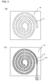
- Fig. 3(a) is a plan view of a ceramic green sheet in which a through-hole is formed
- Fig. 3(b) is a plan view of the ceramic green sheet in Fig. 3(a) after a throwaway piece is fitted in the through-hole.
- the wall part 2 of the spiral channel member 100 as shown in Fig. 1 is made of ceramic, the formation of a through-hole 5 in a thick wall part 2 made of sintered ceramic by a method such as laser processing results in low productivity and high cost. Accordingly, the spiral through-hole 5 may be formed in a ceramic green sheet 16 by press forming or laser processing, which allows the through-hole 5 to be easily formed in a thick wall part 2.
- the ceramic green sheet 16 in which the through-hole 5 is formed has a problem in that it sags near the center thereof while being handled during the manufacturing process because of its softness.
- a wall part 2 composed of a plurality of ceramic green sheets 16 has a problem in that the individual ceramic green sheets 16 vary in the size and position of the through-hole 5 in the center thereof and also deform so as to decrease the width of the through-hole 5.
- the spiral through-hole 5 is formed in each ceramic green sheet 16 by press forming or laser processing, and a throwaway piece 18 cut when the through-hole 5 is formed is fitted back into the through-hole 5.
- the ceramic green sheets 16 are handled in this state until the lamination of the lid part 1 and the bottom plate part 3. Thereafter, the throwaway pieces 18 are removed from the through-hole 5, and the lid part 1 and the bottom plate part 3 are bonded to the ceramic green sheets 16 that are to form the wall part 2. This reduces, for example, the variation in the position of the through-hole 5 in the ceramic green sheets 16 and deformation that decreases the width of the through-hole 5, which tends to occur during handling.
- the throwaway piece 18 illustrated in Fig. 3(b) is formed as one piece extending from the outside to the inside of the through-hole 5, the throwaway piece 18 may be divided and fitted in the entire through-hole 5. If barriers, described later, are provided, the throwaway piece 18 may be partially fitted in the through-hole 18, with a certain space remaining therein. Thus, dividing the throwaway piece 18 into small segments or partially fitting the throwaway piece 18 reduces problems such as deformation and chipping of the throwaway piece 18 until fitting into the through-hole 5 and also facilitates the procedure of removing the throwaway piece 18 from the through-hole 5.
- the width F of the throwaway piece 18 may be somewhat smaller than the width E of the through-hole 5. This facilitates the fitting and removal of the throwaway piece 18 into and from the through-hole 5 and also reduces the risk of damage to the through-hole 5 in the ceramic green sheets 16.
- the width F of the throwaway piece 18 relative to the width E of the through-hole 5 depends on the thickness of the ceramic green sheets 16. For example, if the thickness of the ceramic green sheets 16 after sintering is 0.6 to 1.5 mm, the difference between the width E of the through-hole 5 and the width F of the throwaway piece 18 is preferably 0.2 to 0.6 mm (a clearance of 0.1 to 0.3 mm per side).
- the wall part 2 which is made of a laminate
- the throwaway piece 18 fitted in the through-hole 5 allows uniform pressing, thus reducing problems with bonding due to insufficient pressing. This inhibits delamination (interlayer separation) in the channel 9 of the channel member 100 after firing.
- the throwaway pieces 18 may be removed from the top and bottom of the ceramic green sheets 16 to form the through-hole 5. This method allows the through-hole 5 to have less variation in position and also reduces problems such as deformation that decreases the width of the through-hole 5.
- ceramic green sheets 16 may be used in which the through-hole 5 is formed such that the width of the channel increases from one end to the other end in the height direction.
- the spiral through-hole 5 is formed by laminating a plurality of ceramic green sheets 16 such that the width of the through-hole 5, which is to form the channel 9, is larger near the lid part 1 and is smaller near the bottom plate part 3, the throwaway pieces 18 may be removed in the direction from the bottom plate part 3 toward the lid part 1 after the ceramic green sheets 16 that are to form the wall part 2 are laminated and bonded together by pressing. If the width of the through-hole 5, which is to form the channel 9, is smaller near the lid part 1 and is larger near the bottom plate part 3, the throwaway pieces 18 may be removed in the direction from the lid part 1 toward the bottom plate part 3 after the ceramic green sheets 16 that are to form the wall part 2 are laminated and bonded together by pressing. This allows the laminate to have less variation in the position of the through-hole 5 and less deformation along the width of the through-hole 5.
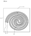
- Fig. 4 is a plan view of another example of a wall part that forms a channel member according to this embodiment.
- a channel member 104 illustrated in Fig. 4 has a spiral channel 9 including a fluid inlet 10 and a fluid outlet 11 at similar positions in the periphery thereof and a turnaround portion 9b near the center thereof.
- the portion of the channel 9 between the inlet 10 and the turnaround portion 9b (hereinafter referred to as "inward path") is adjacent to the portion of the channel 9 between the turnaround portion 9b and the outlet 11 (hereinafter referred to as "outward path"). That is, the channel 9 is formed such that the fluid flows from the periphery to the center and then flows back to the periphery.
- the channel member 104 illustrated in Fig. 4 has the inlet 10 and the outlet 11 for the fluid 23 located in the periphery of the spiral channel 9, the inlet 10 and the outlet 11 may be located near the center of the channel 9, with the turnaround portion 9b located in the periphery thereof.
- This structure allows the fluid 23, serving as a coolant, to be supplied near the center of the lid part 1, on which a heat-generating device is mounted, and also allows the fluid 23 that has reached the highest temperature to be quickly discharged near the center.
- the spiral channel 9 has the inward and outward fluid paths adjacent to each other, when the sheet-shaped bodies 4 that are to form the wall part 2 are formed by forming the through-hole 5 in unfired ceramic green sheets 16, as shown in Fig. 3 , it is effective to form the through-hole 5 in each ceramic green sheet 16 and then fit the throwaway piece 18 into the through-hole 5 to prevent deformation during handling and to ensure that the pressure applied during pressing is transferred to the individual layers when they are bonded together by pressing.
- the wall part of the channel member according to this embodiment preferably has a protrusion and a recess inside the channel.
- the wall part 2 shown in Fig. 2(a) has protrusions above the center thereof and recesses below the center thereof.
- the wall part 2 shown in Fig. 2(b) has the inverted shape of the shape shown in Fig. 2(a) .
- the wall part 2 shown in Fig. 2(c) has protrusions in the center thereof and recesses above and below the center thereof.
- the wall part 2 of the channel member 100 has protrusions and recesses 33 inside the channel 9, the wall part 2 that forms the channel 9 has an increased surface area, and the channel 9 has an increased volume for allowing the fluid to flow therethrough.
- the protrusions and recesses 33 generate turbulence in the fluid, such as a gas or liquid, flowing through the channel member 100, thus improving the heat exchange efficiency between the wall part 2 and the fluid.
- Fig. 5 illustrates another example of a channel member according to this embodiment:
- Fig. 5(a) is a sectional view taken along line A-A in Fig. 1(a)
- Fig. 5(b) is an enlarged view of broken-line area B in Fig. 5(a)
- Fig. 5(c) is an enlarged view of broken-line area C in Fig. 5(a) .
- the maximum difference 33a between the protrusions and recesses 33 of the wall part 2 that forms the channel 9 in the center 34a of the channel member 102 as viewed in a cross section of the channel 9 perpendicular to the direction in which the fluid 23 flows is larger than the maximum difference between the protrusions and recesses 33 of the wall part 2 that forms the channel 9 in the periphery 34b of the channel member 102 (the portions of the wall part 2 inside the channel 9 may be hereinafter referred to as inner walls 35 of the channel 9).
- the inner walls 35 of the channel 9 have the protrusions and recesses 33 as viewed in a cross section of the channel 9 perpendicular to the direction in which the fluid 23 flows, turbulence occurs in the fluid 23 flowing through the channel 9, thus improving the heat exchange efficiency between the channel member 102 and the fluid 23.
- the maximum difference 33a between the protrusions and recesses 33 of the wall part 2 that forms the channel 9 in the center 34a as viewed in a cross section of the channel 9 perpendicular to the direction in which the fluid 23 flows is larger than the maximum difference between the protrusions and recesses 33 of the wall part 2 that forms the channel 9 in the periphery 34b, a larger turbulence occurs in the fluid 23 in the center 34a, thus improving the heat exchange efficiency in the center 34a of the channel member 102.
- the channel member 102 shown in Fig. 5 is used as a channel member for heat exchange with a heat exchange target that generates more heat in the center thereof, it can maintain a uniform temperature throughout the heat exchange target.
- the center 34a of the spiral channel member 102 refers to the region surrounded by a circle that is centered at the midpoint of a line passing through the center of the circle equivalent diameter of the largest portion in which the channel is formed and that has a diameter of 25% of the circle equivalent diameter, and the periphery 34b of the channel member 102 refers to the region outside the center 34b.
- the maximum difference 33a between the protrusions and recesses 33 of the inner walls 35 of the channel 9 in the center 34a and the periphery 34b as viewed in a cross section of the channel 9 perpendicular to the direction in which the fluid 23 flows refers to the maximum difference in step height between the protrusions and recesses 33 of the inner walls 35.
- the maximum difference 33a between the protrusions and recesses 33 of the inner walls 35 in the center 34a as viewed in a cross section of the channel 9 perpendicular to the direction in which the fluid 23 flows is larger than the maximum difference 33a between the protrusions and recesses 33 of the inner walls 35 in the periphery 34b, not only does a larger turbulence occur, but the inner walls 35 also have a larger surface area in contact with the fluid 23, even if the inner diameter of the channel 9 is equal, thus improving the heat exchange efficiency in the center 34a of the channel member 102.
- the channel 9 causes a lower pressure loss as a whole than one having the maximum difference 33a between the protrusions and recesses 33 throughout the entire channel.
- the maximum difference between the protrusions and recesses 33 of the inner walls 35 of the channel 9 in a cross section of the channel 9 perpendicular to the direction in which the fluid 23 flows may increase gradually from the periphery toward the center. Accordingly, the turbulence generated in the fluid 23 by the protrusions and recesses 33 of the inner walls 35 of the channel 9 increases from the periphery 34b toward the center 34a. As a result, the heat exchange efficiency of the channel member 102 is highest in the center 34a and decreases toward the periphery 34b.
- a heat exchange target that exchanges heat with a channel member generates more heat in the center thereof; if such a heat exchange target is mounted in the center of the channel member 102 according to this embodiment, it can lower the temperature in the center, which reaches particularly high temperature. This reduces the temperature gradient between the center and the periphery, thus providing more uniform temperature.
- the maximum difference between the protrusions and recesses of the wall part 2 that forms the channel 9 in the periphery of the channel member may be larger than the maximum difference between the protrusions and recesses of the wall part 2 that forms the channel 9 in the region other than the periphery of the channel member.
- Fig. 6 illustrates another example of a channel member according to this embodiment:
- Fig. 6(a) is a sectional view taken along line A-A in Fig. 1(a)
- Fig. 6(b) is an enlarged view of broken-line area C in Fig. 6(a)
- Fig. 6(c) is an enlarged view of broken-line area B in Fig. 6(a) .
- the wall part 2 have the protrusions and recesses 33 inside the channel 9 as viewed in a cross section of the channel 9 perpendicular to the direction in which the fluid 23 flows and that the maximum difference 33a between the protrusions and recesses 33 of the wall part 2 that forms channel segments 9e in the outermost periphery be larger than the maximum difference 33a between the protrusions and recesses 33 of the wall part 2 that forms channel segments 9c and 9d other than the channel segments 9e in the outermost periphery (the portions of the wall part 2 inside the channel 9 may be hereinafter referred to as the inner walls 35 of the channel 9).
- the inner walls 35 have the protrusions and recesses 33 inside the channel 9 as viewed in a cross section of the channel 9 perpendicular to the direction in which the fluid 23 flows, and the maximum difference 33a between the protrusions and recesses 33 of the inner walls 35 that form the channel segments 9e in the outermost periphery of the channel member 103 is larger than the maximum difference 33a between the protrusions and recesses 33 of the inner walls 35 that form the channel segments 9c and 9d in the region other than the outermost periphery.
- the channel member 103 according to this embodiment is used as a channel member for heat exchange with a heat exchange target that generates more heat in the periphery thereof, it can maintain uniform temperature throughout the heat exchange target.
- the channel 9 causes a lower pressure loss as a whole than one having a large maximum difference 33a between the protrusions and recesses 33 of the inner walls 35 throughout the entire channel. This allows the fluid 23 to flow smoothly, thus improving the heat exchange efficiency of the entire channel member 103 and also improving the heat exchange efficiency in the periphery of the channel member 103, in which heat tends to remain.
- the channel segments 9e in the periphery as viewed in a cross section of the channel 9 perpendicular to the direction in which the fluid 23 flows include at least the channel segments 9e in the outermost periphery.
- the number of channel segments 9e may be set, for example, based on the size of the channel member 102 and the size of the heat exchange target. For example, the number of channel segments 9e may be set within the range of 50% or less of the number of channel segments 9 arranged in a row as viewed in a cross section of the channel 9 perpendicular to the direction in which the fluid 23 flows.
- the maximum difference 33a between the protrusions and recesses 33 of the inner walls 35 that form the channel 9 may be largest in the inner walls 35 of the channel segments 9e in the outermost periphery. This further improves the heat exchange efficiency in the periphery of the channel member 103, in which heat tends to remain.
- heat remaining in the periphery of the channel member 103 may propagate toward and remain in the center thereof.
- the temperature in the center of the spiral channel 9 may rise as the fluid 23 that has exchanged heat in the periphery flows into the center.
- the maximum difference 33a between the protrusions and recesses 33 of the inner walls 35 that form the channel segments 9e in the periphery of the channel member 103 as viewed in a cross section of the channel 9 perpendicular to the direction in which the fluid 23 flows may be larger than the maximum difference 33a between the protrusions and recesses 33 of the inner walls 35 that form the channel segments 9c and 9d in the region other than the periphery, and at the same time, the maximum difference 33a between the protrusions and recesses 33 of the inner walls 35 of the channel segments 9 in the center 34a of the channel member 103 may be larger than the maximum difference 33a between the protrusions and recesses 33 of the inner walls 35 of the channel segments (intermediate channel segments) 9 in the region other than the periphery 34b and the center 34a. That is, the maximum difference 33a between the protrusions and recesses 33 of the inner walls 35 that form the individual channel segments 9 may satisfy the following relationship: intermediate channel segments 10b
- the channel 9 is formed such that the maximum difference 33a between the protrusions and recesses 33 of the inner walls 35 that form the individual channel segments 9 satisfies intermediate channel segments 10b ⁇ central channel segments 10a ⁇ peripheral channel segments 10c, the heat exchange efficiency between the channel member 101 and the fluid 11 can be further improved in the periphery and center thereof. If such a channel member 103 is used as a cooling channel for a heat exchange target in which heat tends to remain in the periphery and center thereof, it can reduce the temperature gradient from the periphery toward the center, thus providing more uniform temperature.
- the channel members 102 and 103 shown in Figs. 5 and 6 may be fabricated as described with reference to Fig. 3 .
- the through-hole 5 may be formed in each ceramic green sheet so as to be shifted from each other.
- Fig. 7 is a partial enlarged sectional view of a channel member 104 according to this embodiment that has gaps 7 leading to the channel 9 between the lid part 1 and the wall part 2 and between the wall part 2 and the bottom plate part 3.
- the channel member 104 has at least one (in Fig. 7 , both) of the gap 7 leading to the channel 9 between the lid part 1 and the wall part 2 and the gap 7 leading to the channel 9 between the wall part 2 and the bottom plate part 3, it has a larger contact area between the channel 9 and the fluid than one having no gap 7. This further improves the heat exchange efficiency between the channel member 104 and the fluid.
- the through-hole that is to form the channel 9 needs to be formed in the sheet-shaped bodies 4 in advance. During the formation of the through-hole, burrs 2c tend to occur at the end surfaces of the through-hole.
- the channel member 104 has at least one of the gap 7 leading to the channel 9 between the lid part 1 and the wall part 2 and the gap 7 leading to the channel 9 between the wall part 2 and the bottom plate part 3, the gap 7 reduces the risk of the burrs 2c entering joints 6 between the lid part 1 and the sheet-shaped bodies 4 that are to form the wall part 2 and between the bottom plate part 3 and the sheet-shaped bodies 4 during the lamination of the lid part 1, the wall part 2, and the bottom plate part 3.
- the channel 9 is resistant to collapse from the joints 6 in the channel 9 when the fluid 23 is supplied at high pressure to the channel member 104.
- Fig. 8 shows sectional views of examples of gaps of channel members according to this embodiment: Fig. 8(a) illustrates a rectangular gap, and Fig. 8(b) illustrates a gap whose width increases toward the channel (hereinafter simply referred to as triangular).
- Channel members 105 and 106 shown in Figs. 8(a) and 8(b) have rectangular and triangular gaps 7, respectively, leading to the channel 9 in the joint 6 between the lid part 1 and the wall part 2 as viewed in a cross section perpendicular to the direction in which the fluid flows.
- the gaps 7 have a distance 7a in the depth direction (hereinafter simply referred to as the depth 7a) and a maximum opening height 7b in the vertical direction (hereinafter simply referred to as the maximum height 7b).
- the lid part 1 may be replaced with the bottom plate part 3 when viewing the figures.
- the shapes of the gaps 7 are not limited to the above shapes.
- the gaps 7 are rectangular or triangular, even if the burrs 2c occur at the end surfaces 2a of the through-hole 5 when the through-hole 5 that is to form the channel 9 is formed in each ceramic green sheet 16 during the process of forming the through-hole 5 for forming the channel 9, the rectangular or triangular gaps 7, which lead to the channel 9 and have the certain depth 7a and maximum height 7b, accommodate the burrs 2c, thus reducing the risk of the burrs 2c entering the joints 6. This reduces problems with the joints between the lid part 1 and the wall part 2 and between the bottom plate part 3 and the wall part 2 and thus allows the channel 9 to be resistant to collapse.
- the wall part 2 is made of a laminate of a plurality of sheet-shaped bodies 4 and has gaps 7 leading to the channel 9 between the sheet-shaped bodies 4 that form the laminate.
- the channel member 104 has the gaps 7 leading to the channel 9 between the sheet-shaped bodies 4, it has a larger contact area between the end surfaces 2a of the wall part 2 and the fluid. This further improves the heat exchange efficiency between the channel member 104 and the fluid.
- gaps 7 leading to the channel 9 in the joints 6 between the sheet-shaped bodies 4 that are to form the wall part 2 reduce the risk of the burrs 2c entering the joints 6 when a plurality of unfired ceramic green sheets 16 that are to form the sheet-shaped bodies 4 are laminated on top of each other during the manufacturing process.
- the gaps 7 may be rectangular, triangular, or trapezoidal.
- Fig. 9 illustrates examples of methods for forming the through-hole that is to form the channel 7 in ceramic green sheets used to form the wall parts of the channel members according to this embodiment:
- Fig. 9(a) is a schematic sectional view illustrating the use of a die
- Fig. 9(b) is a schematic sectional view illustrating the use of laser light
- Figs. 9(c) and 9(d) are partial sectional views taken in a plane perpendicular to the cross sections of the ceramic green sheets formed by the respective methods.
- Fig. 9(a) shows a method for forming the through-hole 5 in a ceramic green sheet 16 using a press-forming apparatus 14.
- the press-forming apparatus 14 includes a punch 14a and a die 14b including chamfering portions 14c for rectangular chamfering.
- rectangular chamfers 16b can be formed at the end surfaces 16a of the through-hole 5 in the ceramic green sheet 16.
- Fig. 9(b) shows a method for forming the through-hole 5 in a ceramic green sheet 16 using a laser processing apparatus 15.
- laser light 15a travels through a lens 15b and is focused near the center of the ceramic green sheet 16 in the thickness direction.
- triangular chamfers 16b can be formed at the end surfaces 16a of the through-hole 5 in the ceramic green sheet 16.
- the channel 9 is formed by the through-hole 5, and the rectangular or triangular gaps 7 leading to the channel 9 can be formed between the lid part 1 and the wall part 2 composed of the sheet-shaped bodies 4 made of the ceramic green sheets 16, between the bottom plate part 3 and the wall part 2, and between the plurality of sheet-shaped bodies 4.
- the volume of the chamfered portion is pressed into the region adjacent to the chamfered portion, thus increasing the density of the ceramic green sheet.
- part of the chamfered portion tends to enter the clearance between the punch and the die and form the burrs 2c at the end surfaces 16a of the through-hole 5
- the gaps 7 between the lid part 1 and the wall part 2, between the bottom plate part 3 and the wall part 2, and between the sheet-shaped bodies 4 that form the wall part 2 reduce the risk of the burrs 2c entering the joints 6.
- the triangular gaps 7 may have a substantially triangular shape such as a wedge or hook shape.
- the chamfering of the end surfaces 16a of the through-hole 5 in the ceramic green sheet 16 tends to leave higher burrs 2c at the end surfaces as the maximum height 7b of the gaps 7 is increased.
- the density increased by the volume of the chamfered portion tends to be concentrated near the end surfaces of the ceramic green sheet. This causes part of the ceramic green sheet to enter the clearance between the punch and the die, thus forming high burrs 2c.
- the channel members 104, 105, and 106 preferably have gaps 7 that satisfy the relationship a > b, where a is the depth 7a of the gaps 7 in the direction in which the gaps 7 extend toward the channel 9, and b is the maximum opening height 7b in the vertical direction, as viewed in a cross section perpendicular to the direction in which the fluid 7 flows.
- the channel 9 is resistant to collapse.
- the depth 7a of the gaps 7 is larger than the maximum height 7b of the gaps 7, the fluid 23 entering the gaps 7 tends to form eddy currents in the gaps 7. This improves the heat exchange efficiency between the fluid and the channel members 104, 105, and 106.
- the gaps 7 of the channel members 101, 102, and 103 according to this embodiment preferably have a depth 7a of 0.03 to 0.08 mm.
- the gaps 7 of the channel members 104, 105, and 106 have a depth 7a of 0.03 mm or more, the gaps 7 further reduce the risk of the burrs 2c reaching and entering the joints 6 as they occur at the end surfaces 16a during the process of forming the through-hole 5 for forming the channel 9. This further reduces problems with the joints 6.
- a larger depth 7a results in a larger surface area of the channel 9 and therefore results in a higher heat exchange efficiency between the fluid and the channel members 104, 105, and 106.
- the gaps 7 have a depth 7a of 0.08 mm or less, a sufficient pressure is applied to the joints 6 when the plurality of ceramic green sheets 16 having the through-hole 5 that is to form the channel 9 are laminated and pressed together during the process of forming the through-hole 5 for forming the channel 9. This reduces problems with bonding in the joints 6.
- the channel 9 of the channel members 104, 105, 106 after firing is resistant to collapse due to cracking from the gaps 7 when a fluid is supplied at high pressure.
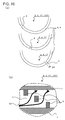
- Fig. 10 illustrates an example of barriers of a channel member according to this embodiment:
- Fig. 10(a) is a set of partial exploded plan views of a wall part composed of three sheet-shaped bodies, showing the relationship between the channel and the barriers of the wall part in the area surrounded by broken line G in Fig. 1(b)
- Fig. 10(b) is a conceptual sectional view showing an arc-shaped portion of the channel of the channel member as extending in a straight line.
- a channel member 107 includes barriers 8 that change the flow of the fluid 23 in the spiral channel 9. Because the barriers 8 change the flow of the fluid 23, as shown in the conceptual view in Fig. 8(b) , the fluid 23 flows beside the barriers 8 while diffusing and mixing repeatedly. This allows a fluid 23 with less temperature variation to contact the channel 9, thus further improving the heat exchange efficiency between the channel member 105 and the fluid 23.
- the wall part 2 is made of a laminate of three sheet-shaped bodies 4 and the barriers 8 are arranged in the individual layers so as to be shifted from each other, any barriers 8 may be provided unless they block the flow of the fluid 23.
- the throwaway piece 18 is fitted into the through-hole 5, for example, to prevent deformation of the ceramic green sheet 17; however, the throwaway piece 18 does not necessarily have to be fitted back into the through-hole 5 if the barriers 8 are provided in the through-hole 5 that is to form the channel 9.
- the barriers 8 reduce problems such as deformation of the through-hole 5 in the ceramic green sheets 17 along the width thereof and sagging near the spiral center.
- the barriers 8 in the channel member 107 are sequentially shifted in the direction in which the fluid 23 flows and in the height direction of the channel 9.
- the barriers 8 are sequentially shifted in the direction in which the fluid 23 flows and in the height direction of the channel 9, with the inlet for the fluid 23 located in the bottom plate part 3, as shown in the conceptual view of the flow of the fluid 23 in Fig. 10(b) , the fluid 23 flows between the barriers 8 while diffusing radially toward the lid part 1.
- a heat exchange target is mounted on the lid part 1, heat exchange occurs efficiently between the lid part 1 and the fluid 23.
- barriers 8 shown in Fig. 10(b) have a rectangular cross section, they may instead have a circular cross section, a polygonal cross section other than rectangular cross sections, or a chamfered rectangular cross section.
- the barriers 8 may be sequentially shifted in the direction in which the fluid 23 flows and in the height direction of the channel 9 in any manner.
- the barriers 8 may be sequentially shifted toward the lid part 1 and then toward the bottom plate part 3 as viewed in the height direction of the channel 9.
- the barriers 8 may be randomly arranged.
- the channel members 100 to 107 according to this embodiment described above, having high heat exchange efficiency, can be used as channel members for cooling semiconductor units and semiconductor manufacturing apparatuses, as channel members for heat exchange with semiconductor manufacturing apparatuses that repeat heating and warming, and as channel members for heat exchangers such as those for chemical solutions and those in printers that generate large amounts of heat.
- a heat exchanger according to this embodiment includes any of the channel members according to this embodiment and a metal member on the lid part.
- the heat exchanger includes any of the channel members 100 to 107 according to this embodiment, which have an inner channel through which a fluid flows, and a metal member on the lid part 1, a heat exchange target mounted on the metal member can efficiently exchange heat with the fluid.
- the metal member is a wiring layer, a semiconductor device, for example, can be directly mounted on the wiring layer, which contributes to lower manufacturing costs.
- the lid part 1 is made of a conductive material such as metal, an insulating material may be disposed on the top surface of the lid part 1, and the metal member may be disposed thereon.
- Fig. 11 is a sectional view of an example of a semiconductor unit including the heat exchanger according to this embodiment and a semiconductor device thereon.
- a semiconductor unit 300 according to this embodiment shown in Fig. 11 includes a heat exchanger 200 including the channel member 100 according to this embodiment and a metal member 22 bonded to the lid part 1 and a semiconductor device 21 on the metal member 22 of the heat exchanger 200.
- the inlet 10 and the outlet 11 for the fluid 23 in the bottom plate part 3 of the channel member 100 are connected to a supply pipe 31 and a discharge pipe 32, respectively, for the fluid 23.
- the fluid 23, serving as a coolant, can be supplied to the channel 9 of the channel member 100 to effectively cool the semiconductor device 21.
- a semiconductor unit 300 resistant to channel collapse and having high heat exchange efficiency can be provided.
- the semiconductor unit 300 can be fabricated by directly forming the wiring layer 22 on the lid part 1, for example, by thick film printing, firing the wiring layer 22, and then mounting and electrically connecting the semiconductor device 21 to the wiring layer 22. This eliminates the need for an electrical insulator between the channel member 100 and the wiring layer 22, thus reducing the number of components, and also improves the cooling efficiency of the semiconductor device 21.
- the semiconductor unit 300 is useful as a unit that generates a large amount of heat during operation, examples of which include car LED headlights, semiconductor modules such as PCUs, direct-current high-voltage power supply units, and switching units.
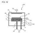
- a semiconductor manufacturing apparatus 400 according to this embodiment shown in Fig. 12 includes the heat exchanger 200 including the channel member 100 according to this embodiment and the metal member 22 bonded to the lid part 1.
- the metal member 22 is an electrode that attracts a semiconductor wafer 29.
- a dielectric layer made of an insulating material is disposed between the electrode 22 and the semiconductor wafer.
- electrostatic attraction such as coulomb force or Johnson-Rahbeck force, occurs between the semiconductor wafer 29 and the dielectric layer to attract and hold the semiconductor wafer 29.
- the metal member 22 of the heat exchanger 200 can be used as a lower electrode 22 for generating plasma.
- a voltage applied between the lower electrode 22 and an antenna electrode 25 disposed in the top of a processing chamber 28 generates plasma between the electrodes 22 and 25.
- the plasma can be applied to the semiconductor wafer 29 attracted and held on the dielectric layer.
- the fluid 23 can be supplied through the supply pipe 31 and the inlet 10 of the channel member 100 and can be discharged through the outlet 11 and the discharge pipe 32 to cool the lower electrode 22, which reaches high temperature during plasma processing, thereby maintaining stable temperature. Accordingly, the temperature of the wafer 29 is controlled, thus allowing processing with high dimensional accuracy.
- the metal member 22 of the semiconductor manufacturing apparatus 400 may be divided and used as a bipolar electrode 22 composed of two electrodes. Alternatively, the metal member 22 may be disposed in the lid part 1 of the channel member 100.
- the semiconductor manufacturing apparatus 400 can be used, for example, as a sputtering apparatus, a resist coating apparatus, or a CVD apparatus.
- the metal member 22 of the heat exchanger 200 can be used as an electrode and as a table on which the semiconductor wafer 29 is placed to inhibit an excessive temperature rise in the semiconductor wafer 29.
- the semiconductor manufacturing apparatus 400 can also be used as an etching apparatus.
- the lid part 1, the wall part 2, and the bottom plate part 3 of the channel member 100 were fabricated using alumina ceramic.
- the channel member 100 was examined for the relationship between the cooling performance provided when the fluid 23 is supplied to the channel 9 and whether or not the channel member 100 has the gaps 7 leading to the channel 9 in the joints 6 between the lid part 1 and the wall part 2, between the bottom plate part 3 and the wall part 2, and if the wall part 2 is made of a laminate of a plurality of sheet-shaped bodies 4, between the sheet-shaped bodies 4.
- the channel member 100 had an overall length L of 100 mm, a width D of 100 mm, and a height H of 50 mm.
- the lid part 1 had a thickness t1 of 0.5 mm.
- the sheet-shaped body 4 used to form a single-layer wall part 2 had a thickness t2 of 3 mm.
- the sheet-shaped bodies 4 used to form a three-layer wall part 2 each had a thickness t2 of 1 mm.
- the bottom plate part 3 had a thickness t3 of 2.5 mm.
- the channel 9 was spiral in plan view and had a width D1 of 4 mm.
- the width D2 between the channel segments 9 was 4 to 6 mm.
- the inlet 10 for the fluid 23 was located in the bottom plate part 3.
- the spiral channel 9 was configured to allow the fluid 23 to enter the channel 9 in the periphery thereof and to exit the channel 9 through the outlet 11 in the bottom plate part 3 near the center thereof, which was the endpoint of the channel 9.
- the ceramic green sheets used to form the channel member 100 were first fabricated by the following method.
- alumina (Al 2 O 3 ) powder having an average particle size of about 1.6 ⁇ m and silica (SiO 2 ), calcia (CaO), and magnesia (MgO) powders were prepared.
- powders were weighed and mixed to prepare a powder mixture containing 96.4% by mass alumina, 2.3% by mass silica, 0.3% by mass calcia, and 1.0% by mass magnesia.
- the powder mixture was charged into a rotating mill together with polyethylene glycol as a binder in an amount of 6% by mass based on 100% by mass of the powder mixture and was mixed with high-purity alumina balls.
- An acrylic resin was then added to the mixture as a binder in an amount of 4% by mass based on 100% by mass of the powder mixture and was mixed to prepare a slurry.
- the resulting slurry was then applied by a known process, i.e., doctor blade coating, to form ceramic green sheets.
- a known process i.e., doctor blade coating
- Each ceramic green sheet was processed using a press-forming apparatus equipped with a die so as to form the product shape when laminated.
- the sheet-shaped bodies 4 used to form the wall part 2 were each formed as one piece extending to the periphery thereof, including the portion adjacent to the channel 9.
- Samples including a single-layer wall part 2 and samples including a multilayer wall part 2 were then fabricated, including, as shown in Fig. 7 , samples having gaps 7 with no depth 7a (in practice, a depth 7a of less than 0.01 mm is assumed to be no depth 7a), samples having gaps 7 with a depth 7a, samples having gaps 7 with no maximum height 7b (in practice, a maximum height 7b of less than 0.01 mm is assumed to be no maximum height 7b), and samples having gaps 7 with a maximum height 7b.
- 300 samples were fabricated. These are referred to as Sample Nos. 1 to 9.
- the dimensions of the gaps 7 in Table 1 are those measured after firing.
- the gaps 7 had a triangular shape open toward the channel 9.
- the sheet-shaped bodies 4 used to form the wall part 2 were fabricated by forming the through-hole 5 in each ceramic green sheet 16, the chamfers 16b were formed at the end surfaces 16a of the through-hole 5 in the ceramic green sheet 16 using the press-forming apparatus 14.
- the resulting ceramic green sheets 16 used to form the lid part 1, the wall part 2, and the bottom plate part 3 were laminated on top of each other. As shown in Fig. 3 , the method was used in which the throwaway piece 18 cut when the through-hole 5 was formed in each ceramic green sheet 16 was fitted in the through-hole 5.
- the laminated ceramic green sheets 16 were then bonded together by pressing.
- a bonding solution serving as an adhesive was applied in advance to the portions that were to form the joints 6.
- the bonding solution used was the same binder as used to fabricate the ceramic green sheets 16.
- the bonding solution was applied to the entire surface of each ceramic green sheet 16 to be laminated.
- the ceramic green sheets 16 to which the bonding solution was applied were laminated and bonded together by pressing the top and bottom of the laminated ceramic green sheets 16 between flat plates at a pressure of about 0.5 MPa.
- the resulting samples were then cut to measure the depth (a) and maximum height (b) of the gaps 7 in the cross section under a factory microscope.
- the depth (a) and maximum height (b) of the gaps 7 are the average depth (a) and maximum height (b) of two gaps 7 near the periphery of the spiral channel 9, two gaps 7 near the center of the spiral channel 9, and two gaps 7 between the periphery and the center of the spiral channel 9, i.e., a total of six gaps 7.
- Each sample was then tested by placing a heat exchange target on the lid part 1 and causing it to generate heat to determine the cooling performance ratio depending on the presence of the gaps 7 leading to the channel 9 in the joints 6 between the lid part 1 and the wall part 2 of the channel member 100, between the bottom plate part 3 and the wall part 2, and between the three sheet-shaped bodies 4 that formed the wall part 2.
- each sample was tested by attaching a heater and a thermocouple to the outer surface of the lid part 1 and heating it to a predetermined temperature.
- a fluid 23 at a predetermined temperature was then supplied to the channel member 100 at a predetermined pressure.
- the temperature of the outer surface of the lid part 1 was measured to determine the average temperature change in each sample.
- Sample No. 1 included a single-layer wall part 2 and had no gaps 7 open in the channel 9 in the joint 6 between the lid part 1 or bottom plate part 3 and the wall part 2.
- the average temperature change in this sample was used as a reference, and the average temperature changes in the other samples were expressed as the ratio to the reference, which is the cooling performance ratio.
- Sample Nos. 2 to 9 which had the gaps 7 in any of the joints 6, had high cooling performance ratios, i.e., 1.14 to 1.22, as compared to Sample No. 1, which included a single-layer wall part 2 and had substantially no gaps 7 leading to the channel 9 between the lid part 1 and the wall part 2 or between the bottom plate part 3 and the wall part 2.
- Example 2 differs from Example 1 in that the channel member 107 had substantially no gaps 7, i.e., less than 0.01 mm, leading to the channel 9 in the joints 6 and included the barriers 8.
- the necessary size and number of barriers 8 can be formed by dividing the punch 14a of the press-forming apparatus 14 for forming the through-hole 5.
- the barriers 8 had a width D3 of 3 mm after firing.
- Sample No. 14 which included the barriers 8 arranged in each sheet-shaped body 4 so as to be shifted in the order of the layers, had the highest cooling performance ratio relative to the cooling performance ratio of Sample No. 10.
- Sample No. 12 which included the barriers 8 arranged only in the sheet-shaped body 4 located in the middle of the wall part 2, had the second highest cooling performance ratio.
- Sample No. 13 which included the barriers 8 arranged in the sheet-shaped body 4 adjacent to the bottom plate part 3, had the third highest cooling performance ratio.
- Sample No. 11 which included the barriers 8 arranged in the sheet-shaped body 4 adjacent to the lid part 1, had the fourth highest cooling performance ratio.
Landscapes
- Engineering & Computer Science (AREA)
- Physics & Mathematics (AREA)
- Plasma & Fusion (AREA)
- Chemical & Material Sciences (AREA)
- Analytical Chemistry (AREA)
- Thermal Sciences (AREA)
- Mechanical Engineering (AREA)
- General Engineering & Computer Science (AREA)
- Ceramic Engineering (AREA)
- Cooling Or The Like Of Semiconductors Or Solid State Devices (AREA)
- Cooling Or The Like Of Electrical Apparatus (AREA)
Abstract
Description
- The present invention relates to channel members and to heat exchangers, semiconductor units, and semiconductor manufacturing apparatuses including such channel members.
- The trend toward smaller electronic components in recent years has resulted in higher packing densities and higher speeds of semiconductor devices mounted thereon. Accordingly, the amount of heat generated from semiconductor devices has increased, and electronic components have been used at higher temperatures. Thus, there is an increasing need to cool electronic components.
- As an example of means for cooling electronic components, PTL 1 proposes a copper or aluminum channel member having a spiral channel and built into a power semiconductor device that reaches high temperature.
- PTL 1: Japanese Unexamined Patent Application Publication No.
6-268127 - However, because the channel member disclosed in
PTL 1 is made of copper or aluminum, it has a problem in that the use of a fluid highly corrosive to metals, such as lithium bromide, results in corrosion of the wall surfaces of the channel and therefore results in collapse of the channel walls when the fluid is supplied at high pressure. - In view of the foregoing problem, an object of the present invention is to provide a channel member including channel walls resistant to corrosion and therefore resistant to collapse and a heat exchanger, semiconductor unit, and semiconductor manufacturing apparatus including such a channel member.
- A channel member according to the present invention has an inner spiral channel through which a fluid flows. The channel is formed by a lid part, a bottom plate part, and a wall part connected to the lid part and the bottom plate part. The wall part is made of a ceramic laminate.
- A heat exchanger according to the present invention includes the above channel member and a metal member on or in the lid part.
- A semiconductor unit according to the present invention includes the above heat exchanger, with the metal member on the lid part, and a semiconductor device on the metal member.
- A semiconductor manufacturing apparatus according to the present invention includes the above heat exchanger, and the metal member is an electrode that attracts a semiconductor wafer.
- The channel member according to the present invention has the inner spiral channel through which the fluid flows, the channel is formed by the lid part, the bottom plate part, and the wall part connected to the lid part and the bottom plate part, and the wall part is made of a ceramic laminate; thus, the channel walls are resistant to corrosion and are therefore resistant to collapse.
- Because the heat exchanger according to the present invention includes the above channel member and the metal member on the lid part, the heat exchanger allows efficient heat exchange between the lid part and the metal member, thus providing high heat exchange efficiency.
- The semiconductor unit according to the present invention includes the above heat exchanger and the semiconductor device on the metal member; with such a simple structure, the semiconductor unit can reduce the temperature rise due to heat generated from the semiconductor device.
- The semiconductor manufacturing apparatus according to the present invention includes the above heat exchanger, and the metal member is an electrode that attracts a semiconductor wafer; thus, the metal member can be used both as a table on which the semiconductor wafer is placed and as a processing electrode. With such a simple structure, the semiconductor manufacturing apparatus can reduce the generation of heat from the electrode and can therefore reduce the temperature rise in the wafer, thus allowing the manufacture of semiconductor devices with high dimensional accuracy.
-
- [
Fig. 1] Fig. 1 illustrates an example of a channel member according to an embodiment:Fig. 1(a) is a perspective view of the channel member,Fig. 1(b) is a plan view of a wall part that forms the channel member, andFig. 1(c) is a sectional view taken along line A-A inFig. 1(a) . - [
Fig. 2] Fig. 2 illustrates other examples of cross-sectional shapes of the channel member according to this embodiment perpendicular to the direction in which a fluid flows, showing enlarged sectional views of the area surrounded by the broken line in the sectional view inFig. 1(c) :Figs. 2(a) and 2(b) illustrate examples in which the width of the channel increases from one end toward the other end in the height direction of the channel, andFig. 2(c) illustrates an example in which the width of the channel increases from the center toward both ends in the height direction of the channel. - [
Fig. 3] Fig. 3 illustrates an example of a process of fabricating the wall part of the channel member according to this embodiment:Fig. 3(a) is a plan view of a ceramic green sheet in which a through-hole is formed, andFig. 3(b) is a plan view of the ceramic green sheet inFig. 3(a) after a throwaway piece is fitted in the through-hole. - [
Fig. 4] Fig. 4 is a plan view of another example of a wall part that forms a channel member according to this embodiment. - [
Fig. 5] Fig. 5 illustrates another example of a channel member according to this embodiment:Fig. 5(a) is a sectional view taken along line A-A inFig. 1(a) ,Fig. 5(b) is an enlarged view of broken-line area B inFig. 5(a), and Fig. 5(c) is an enlarged view of broken-line area C inFig. 5(a) . - [
Fig. 6] Fig. 6 illustrates still another example of a channel member according to this embodiment:Fig. 6(a) is a sectional view taken along line A-A inFig. 1(a) ,Fig. 6(b) is an enlarged view of broken-line area C inFig. 6(a), and Fig. 6(c) is an enlarged view of broken-line area B inFig. 6(a) . - [
Fig. 7] Fig. 7 is a partial enlarged sectional view of a channel member according to this embodiment that has gaps leading to the channel between the lid part, the wall part, and the bottom plate part. - [
Fig. 8] Fig. 8 illustrates other examples of this embodiment:Fig. 8(a) is a sectional view of a rectangular gap, andFig. 8(b) is a sectional view of a gap whose width increases toward the channel. - [
Fig. 9] Fig. 9 illustrates examples of methods for forming the through-hole that is to form the channel in ceramic green sheets used to form the wall parts of the channel members according to this embodiment:Fig. 9(a) is a schematic sectional view illustrating the use of a die,Fig. 9(b) is a schematic sectional view illustrating the use of laser light, andFigs. 9(c) and 9(d) are partial sectional views taken in a plane perpendicular to cross sections of the ceramic green sheets formed by the respective methods. - [
Fig. 10] Fig. 10 illustrates an example of barriers of a channel member according to this embodiment:Fig. 10(a) is a set of partial exploded plan views of a wall part composed of three sheet-shaped bodies, showing the relationship between the channel and the barriers of the wall part in the area surrounded by broken line G inFig. 1(b) , andFig. 10(b) is a conceptual sectional view showing an arc-shaped portion of the channel as extending in a straight line. - [
Fig. 11] Fig. 11 is a sectional view of an example of a semiconductor unit including a heat exchanger according to this embodiment and a semiconductor device thereon. - [
Fig. 12] Fig. 12 is a schematic view of an example of the overall system configuration of a semiconductor manufacturing apparatus including the heat exchanger according to this embodiment. - Embodiments of the present invention will be described below.
- An example of an embodiment of a channel member according to the present invention will now be described with reference to
Fig. 1 . -
Fig. 1 illustrates an example of a channel member according to this embodiment:Fig. 1(a) is a perspective view of the channel member,Fig. 1(b) is a plan view of a wall part that forms the channel member, andFig. 1(c) is a sectional view of a channel shown inFig. 1(a) taken along line A-A, which passes through substantially the center of the channel in plan view. - As shown in
Figs. 1(a) to 1(c) , achannel member 100 according to this embodiment is composed of alid part 1, awall part 2, and abottom plate part 3 and has an innerspiral channel 9 through which afluid 23, such as a gas or liquid, flows. - It is important that the
channel member 100 according to this embodiment have the innerspiral channel 9 through which thefluid 23 flows, that thechannel 9 be formed by thelid part 1, thebottom plate part 3, and thewall part 2 connected to thelid part 1 and thebottom plate part 3, and that thewall part 2 be made of a ceramic laminate. - Because the
channel 9 through which thefluid 23 flows in thechannel member 100 according to this embodiment has a spiral shape, the contact area between thefluid 23 and thechannel member 100 can be increased despite its compact structure, thus providing high heat exchange efficiency. In addition, because thechannel 9 is formed by thewall part 2 connected to thelid part 1 and thebottom plate part 3, thechannel 9 can be easily formed in a complicated pattern by forming a hole that is to form thechannel 9 using thewall part 2 alone in advance and then placing thelid part 1 thebottom plate part 3 on thewall part 2. - Because the
wall part 2 is made of a ceramic, the channel walls of thewall part 2 are resistant to corrosion and are therefore resistant to collapse even if thefluid 23 is a fluid highly corrosive to metals, such as lithium bromide. Because thewall part 2 is made of a laminate, the cross-sectional area of thechannel 9 can be easily increased. In other words, the contact area between thewall part 2 and thefluid 23 can be increased. This improves the heat exchange efficiency between the channel member 101 and the fluid. The reason why the cross-sectional area of thechannel 9 can be easily increased if thewall part 2 is made of a laminate will be described later. - The
lid part 1 and thebottom plate part 3 may be made of materials such as ceramics, metals, and resins. Preferably, thelid part 1 and thebottom plate part 3 are made of materials with high heat and corrosion resistance. In particular, it is desirable that thelid part 1 be made of an insulating material that has high thermal conductivity and that allows wiring layers such as electrodes to be directly mounted thereon. - Examples of ceramics that can be used as the materials for the
wall part 2, thelid part 1, and thebottom plate part 3 include alumina, silicon nitride, aluminum nitride, silicon carbide, mullite, zirconia, and composites thereof. - If the
lid part 1, thewall part 2, and thebottom plate part 3 are made of ceramics, they may be formed using ceramic green sheets and may then be bonded and fired together. If thelid part 1 and thebottom plate part 3 are made of metal or resin materials, thelid part 1 and thebottom plate part 3 may be placed on a sinteredceramic wall part 2 fired in advance and may then be secured thereto, for example, using screws, by crimping a metal frame (not shown), or by brazing. - In
Fig. 1 , thechannel member 100 has aninlet 10 and anoutlet 11 for thefluid 23 in the bottom of thebottom plate part 3 and is configured such that thefluid 23 is supplied from the outside of thespiral channel 9 and is discharged from the inside of thechannel 9. Thechannel member 100, however, is not necessarily configured as above, but may be configured such that thefluid 23 is supplied or discharged from thelid part 1 or thewall part 2. For example, theinlet 10 and theoutlet 11 may be provided at appropriate positions depending on the installation site and maintenance of thechannel member 100. Although thechannel 9 illustrated herein has a circular spiral shape, it may have any other spiral shape, such as a triangular or rectangular spiral shape. - As an example of such a channel member, one having the
inlet 10 and theoutlet 11 for thefluid 23 in thelid part 1 facilitates maintenance, for example, when provided inside a car hood. As another example, one having theinlet 10 and theoutlet 11 in the same side surface of thewall part 2 allows the use of simple piping for supplying and discharging thefluid 23 in power semiconductor units and semiconductor manufacturing apparatuses used in semiconductor manufacturing processes. -
Fig. 2 illustrates other examples of cross-sectional shapes of thechannel 9 of thechannel member 100 according to this embodiment perpendicular to the direction in which the fluid flows, showing enlarged sectional views of area B surrounded by the broken line in the sectional view inFig. 1(c) :Figs. 2(a) and 2(b) illustrate examples in which the width of the channel increases from one end toward the other end in the height direction of the channel, andFig. 2(c) illustrates an example in which the width of thechannel 9 increases from the center toward both ends in the height direction of the channel.Fig. 2(a) illustrates an example in which the width of thechannel 9 is smaller near thelid part 1 and is larger near thebottom plate part 3, andFig. 2(b) illustrates an example in which the width of thechannel 9 is larger near thelid part 1 and is smaller near thebottom plate part 3. - In the channel member according to this embodiment, the width of the channel as viewed in a cross section of the channel perpendicular to the direction in which the fluid flows preferably increases from one end toward the other end in the height direction of the channel.
- For example, if the
inlet 10 and theoutlet 11 for the fluid 23 are located in thelid part 1 or at positions near thelid part 1 in thewall part 2, the width of thechannel 9 may increase from thelid part 1 toward thebottom plate part 3, as shown inFig. 2(a) , so that the fluid 23 supplied to thechannel 9 flows more easily from the top (near the lid part 1) to the bottom (near the bottom plate part 3) of thechannel 9 while circulating through thespiral channel 9. The flow of the fluid 23 to the top of thechannel 9 gains velocity with decreasing width of thechannel 9. For example, if a heat exchange target, such as a semiconductor device, is mounted on thelid part 1, which is therefore more influenced by the heat exchange target, the fluid 23 flows quickly near thelid part 1 and forms a flow that contacts thelid part 1. This facilitates the heat exchange between thelid part 1 and the fluid 23, thus efficiently cooling the heat exchange target. - If the
inlet 10 and theoutlet 11 for the fluid 23 are located in thebottom plate part 3, the width of thechannel 9 may increase from thebottom plate part 3 toward thelid part 1, as shown inFig. 2(b) , so that the fluid 23 supplied to thechannel 9 flows more easily from the bottom (near the bottom plate part 3) to the top (near the lid part 1) of thechannel 9 while circulating through thespiral channel 9. For example, if a heat exchange target, such as a semiconductor device, is mounted on thelid part 1, the larger contact area between thelid part 1 and the fluid 23 facilitates the heat exchange between thelid part 1 and the fluid 23, thus efficiently cooling the heat exchange target. The example illustrated inFig. 2(b) is particularly preferred because it is less influenced by the positions of the fluid inlet and outlet. - In
Figs. 2(a) and 2(b) , thewall part 2 is composed of three sheet-shapedbodies 4, and the width of thechannel 9 increases stepwise in a rectangular shape from one end to the other end in the height direction of thechannel 9. The width of thechannel 9, however, may change in an inclined or curved shape from one end to the other end in the height direction of thechannel 9. Theinlet 10 and theoutlet 11 may be provided at appropriate positions depending on the purpose of the channel member. - In the
channel member 100 according to this embodiment shown inFig. 2(c) , the width of thechannel 9 as viewed in a cross section of thechannel 9 perpendicular to the direction in which the fluid flows is smaller in the center of thechannel 9 than near thelid part 1 and thebottom plate part 3 in the height direction of thechannel 9. - For example, as shown in
Fig. 1(c) , if theinlet 10 and theoutlet 11 for the fluid 23 are located in thebottom plate part 3 in the example in which the width of thechannel 9 is smaller in the center thereof, the fluid 23 supplied to thechannel 9 flows from the bottom (near the bottom plate part 3) to the top (near the lid part 1) of thechannel 9 while circulating through thespiral channel 9. The narrow center of thechannel 9 in the height direction mixes the fluid 23 that has exchanged heat with thewall part 2 with the fluid 23 flowing at a position away from thewall part 2 and further diffuses the fluid 23 toward thelid part 1 and thebottom plate part 3 while increasing the velocity thereof. This further improves the heat exchange efficiency between thechannel member 100 and the fluid 23. - In
Figs. 2(c) , thewall part 2 is composed of three sheet-shapedbodies 4, and the width of thechannel 9 is smaller in the center thereof and increases stepwise from the center thereof toward thelid part 1 and thebottom plate part 3. The width of thechannel 9, however, may change in an inclined or curved shape. -
Fig. 3 illustrates an example of a process of fabricating thewall part 2 of the channel member according to this embodiment:Fig. 3(a) is a plan view of a ceramic green sheet in which a through-hole is formed, andFig. 3(b) is a plan view of the ceramic green sheet inFig. 3(a) after a throwaway piece is fitted in the through-hole. - If the
wall part 2 of thespiral channel member 100 as shown inFig. 1 is made of ceramic, the formation of a through-hole 5 in athick wall part 2 made of sintered ceramic by a method such as laser processing results in low productivity and high cost. Accordingly, the spiral through-hole 5 may be formed in a ceramicgreen sheet 16 by press forming or laser processing, which allows the through-hole 5 to be easily formed in athick wall part 2. - However, the ceramic
green sheet 16 in which the through-hole 5 is formed has a problem in that it sags near the center thereof while being handled during the manufacturing process because of its softness. Thus, awall part 2 composed of a plurality of ceramicgreen sheets 16 has a problem in that the individual ceramicgreen sheets 16 vary in the size and position of the through-hole 5 in the center thereof and also deform so as to decrease the width of the through-hole 5. - An example of a solution to this problem is as follows. The spiral through-
hole 5 is formed in each ceramicgreen sheet 16 by press forming or laser processing, and athrowaway piece 18 cut when the through-hole 5 is formed is fitted back into the through-hole 5. The ceramicgreen sheets 16 are handled in this state until the lamination of thelid part 1 and thebottom plate part 3. Thereafter, thethrowaway pieces 18 are removed from the through-hole 5, and thelid part 1 and thebottom plate part 3 are bonded to the ceramicgreen sheets 16 that are to form thewall part 2. This reduces, for example, the variation in the position of the through-hole 5 in the ceramicgreen sheets 16 and deformation that decreases the width of the through-hole 5, which tends to occur during handling. - Although the
throwaway piece 18 illustrated inFig. 3(b) is formed as one piece extending from the outside to the inside of the through-hole 5, thethrowaway piece 18 may be divided and fitted in the entire through-hole 5. If barriers, described later, are provided, thethrowaway piece 18 may be partially fitted in the through-hole 18, with a certain space remaining therein. Thus, dividing thethrowaway piece 18 into small segments or partially fitting thethrowaway piece 18 reduces problems such as deformation and chipping of thethrowaway piece 18 until fitting into the through-hole 5 and also facilitates the procedure of removing thethrowaway piece 18 from the through-hole 5. - The width F of the
throwaway piece 18 may be somewhat smaller than the width E of the through-hole 5. This facilitates the fitting and removal of thethrowaway piece 18 into and from the through-hole 5 and also reduces the risk of damage to the through-hole 5 in the ceramicgreen sheets 16. - For example, the width F of the
throwaway piece 18 relative to the width E of the through-hole 5 depends on the thickness of the ceramicgreen sheets 16. For example, if the thickness of the ceramicgreen sheets 16 after sintering is 0.6 to 1.5 mm, the difference between the width E of the through-hole 5 and the width F of thethrowaway piece 18 is preferably 0.2 to 0.6 mm (a clearance of 0.1 to 0.3 mm per side). - In particular, when the
wall part 2, which is made of a laminate, is fabricated by applying a binder to a plurality of ceramicgreen sheets 16, laminating the ceramicgreen sheets 16 on top of each other, and bonding the ceramicgreen sheets 16 together by pressing, thethrowaway piece 18 fitted in the through-hole 5 allows uniform pressing, thus reducing problems with bonding due to insufficient pressing. This inhibits delamination (interlayer separation) in thechannel 9 of thechannel member 100 after firing. - As a method for manufacturing a channel member having the
channel 9 as shown inFig. 2(c) , after the ceramicgreen sheets 16 that are to form thewall part 2 are laminated and bonded together by pressing, thethrowaway pieces 18 may be removed from the top and bottom of the ceramicgreen sheets 16 to form the through-hole 5. This method allows the through-hole 5 to have less variation in position and also reduces problems such as deformation that decreases the width of the through-hole 5. - As a method for manufacturing a channel member having the
channel 9 as shown inFig. 2(a) or 2(b) , ceramicgreen sheets 16 may be used in which the through-hole 5 is formed such that the width of the channel increases from one end to the other end in the height direction. - If the spiral through-
hole 5 is formed by laminating a plurality of ceramicgreen sheets 16 such that the width of the through-hole 5, which is to form thechannel 9, is larger near thelid part 1 and is smaller near thebottom plate part 3, thethrowaway pieces 18 may be removed in the direction from thebottom plate part 3 toward thelid part 1 after the ceramicgreen sheets 16 that are to form thewall part 2 are laminated and bonded together by pressing. If the width of the through-hole 5, which is to form thechannel 9, is smaller near thelid part 1 and is larger near thebottom plate part 3, thethrowaway pieces 18 may be removed in the direction from thelid part 1 toward thebottom plate part 3 after the ceramicgreen sheets 16 that are to form thewall part 2 are laminated and bonded together by pressing. This allows the laminate to have less variation in the position of the through-hole 5 and less deformation along the width of the through-hole 5. -
Fig. 4 is a plan view of another example of a wall part that forms a channel member according to this embodiment. - A
channel member 104 illustrated inFig. 4 has aspiral channel 9 including afluid inlet 10 and afluid outlet 11 at similar positions in the periphery thereof and aturnaround portion 9b near the center thereof. The portion of thechannel 9 between theinlet 10 and theturnaround portion 9b (hereinafter referred to as "inward path") is adjacent to the portion of thechannel 9 between theturnaround portion 9b and the outlet 11 (hereinafter referred to as "outward path"). That is, thechannel 9 is formed such that the fluid flows from the periphery to the center and then flows back to the periphery. - Thus, for example, if a heat exchange target is mounted on the
lid part 1 bonded to thewall part 2 of thechannel member 104 having thespiral channel 9 including theturnaround portion 9b, heat exchange occurs between the adjacent inward and outward paths. This reduces the temperature variation near the center and in the periphery of thelid part 1. In addition, because theinlet 10 and theoutlet 11 for the fluid 23 can be provided close to each other, a fluid supply pipe to which theinlet 10 for the fluid 23 is connected and a fluid discharge pipe to which theoutlet 11 for the fluid 23 is connected can be provided close to each other when thechannel member 104 is used as a heat exchanger (hereinafter not shown) in a semiconductor unit or semiconductor manufacturing apparatus. This simplifies the structure of the apparatus and facilitates maintenance. - Although the
channel member 104 illustrated inFig. 4 has theinlet 10 and theoutlet 11 for the fluid 23 located in the periphery of thespiral channel 9, theinlet 10 and theoutlet 11 may be located near the center of thechannel 9, with theturnaround portion 9b located in the periphery thereof. This structure allows the fluid 23, serving as a coolant, to be supplied near the center of thelid part 1, on which a heat-generating device is mounted, and also allows the fluid 23 that has reached the highest temperature to be quickly discharged near the center. - Because the
spiral channel 9 has the inward and outward fluid paths adjacent to each other, when the sheet-shapedbodies 4 that are to form thewall part 2 are formed by forming the through-hole 5 in unfired ceramicgreen sheets 16, as shown inFig. 3 , it is effective to form the through-hole 5 in each ceramicgreen sheet 16 and then fit thethrowaway piece 18 into the through-hole 5 to prevent deformation during handling and to ensure that the pressure applied during pressing is transferred to the individual layers when they are bonded together by pressing. - The wall part of the channel member according to this embodiment preferably has a protrusion and a recess inside the channel.
- For example, the
wall part 2 shown inFig. 2(a) has protrusions above the center thereof and recesses below the center thereof. Thewall part 2 shown inFig. 2(b) has the inverted shape of the shape shown inFig. 2(a) . Thewall part 2 shown inFig. 2(c) has protrusions in the center thereof and recesses above and below the center thereof. - Because the
wall part 2 of thechannel member 100 according to this embodiment has protrusions and recesses 33 inside thechannel 9, thewall part 2 that forms thechannel 9 has an increased surface area, and thechannel 9 has an increased volume for allowing the fluid to flow therethrough. In addition, the protrusions and recesses 33 generate turbulence in the fluid, such as a gas or liquid, flowing through thechannel member 100, thus improving the heat exchange efficiency between thewall part 2 and the fluid. -
Fig. 5 illustrates another example of a channel member according to this embodiment:Fig. 5(a) is a sectional view taken along line A-A inFig. 1(a) ,Fig. 5(b) is an enlarged view of broken-line area B inFig. 5(a), and Fig. 5(c) is an enlarged view of broken-line area C inFig. 5(a) . - In a
channel member 102 shown inFig. 5 , themaximum difference 33a between the protrusions and recesses 33 of thewall part 2 that forms thechannel 9 in thecenter 34a of thechannel member 102 as viewed in a cross section of thechannel 9 perpendicular to the direction in which the fluid 23 flows is larger than the maximum difference between the protrusions and recesses 33 of thewall part 2 that forms thechannel 9 in theperiphery 34b of the channel member 102 (the portions of thewall part 2 inside thechannel 9 may be hereinafter referred to asinner walls 35 of the channel 9). - Because the
inner walls 35 of thechannel 9 have the protrusions and recesses 33 as viewed in a cross section of thechannel 9 perpendicular to the direction in which the fluid 23 flows, turbulence occurs in the fluid 23 flowing through thechannel 9, thus improving the heat exchange efficiency between thechannel member 102 and the fluid 23. - In addition, because the
maximum difference 33a between the protrusions and recesses 33 of thewall part 2 that forms thechannel 9 in thecenter 34a as viewed in a cross section of thechannel 9 perpendicular to the direction in which the fluid 23 flows is larger than the maximum difference between the protrusions and recesses 33 of thewall part 2 that forms thechannel 9 in theperiphery 34b, a larger turbulence occurs in the fluid 23 in thecenter 34a, thus improving the heat exchange efficiency in thecenter 34a of thechannel member 102. - Thus, in particular, if the
channel member 102 shown inFig. 5 is used as a channel member for heat exchange with a heat exchange target that generates more heat in the center thereof, it can maintain a uniform temperature throughout the heat exchange target. - The
center 34a of thespiral channel member 102 refers to the region surrounded by a circle that is centered at the midpoint of a line passing through the center of the circle equivalent diameter of the largest portion in which the channel is formed and that has a diameter of 25% of the circle equivalent diameter, and theperiphery 34b of thechannel member 102 refers to the region outside thecenter 34b. - In this embodiment, as shown in
Figs. 5(b) and 5(c) , themaximum difference 33a between the protrusions and recesses 33 of theinner walls 35 of thechannel 9 in thecenter 34a and theperiphery 34b as viewed in a cross section of thechannel 9 perpendicular to the direction in which the fluid 23 flows refers to the maximum difference in step height between the protrusions and recesses 33 of theinner walls 35. If themaximum difference 33a between the protrusions and recesses 33 of theinner walls 35 in thecenter 34a as viewed in a cross section of thechannel 9 perpendicular to the direction in which the fluid 23 flows is larger than themaximum difference 33a between the protrusions and recesses 33 of theinner walls 35 in theperiphery 34b, not only does a larger turbulence occur, but theinner walls 35 also have a larger surface area in contact with the fluid 23, even if the inner diameter of thechannel 9 is equal, thus improving the heat exchange efficiency in thecenter 34a of thechannel member 102. - In addition, if the
maximum difference 33a between the protrusions and recesses 33 of theinner walls 35 of thechannel 9 is larger in thecenter 34a than in theperiphery 34b, thechannel 9 causes a lower pressure loss as a whole than one having themaximum difference 33a between the protrusions and recesses 33 throughout the entire channel. - The maximum difference between the protrusions and recesses 33 of the
inner walls 35 of thechannel 9 in a cross section of thechannel 9 perpendicular to the direction in which the fluid 23 flows may increase gradually from the periphery toward the center. Accordingly, the turbulence generated in the fluid 23 by the protrusions and recesses 33 of theinner walls 35 of thechannel 9 increases from theperiphery 34b toward thecenter 34a. As a result, the heat exchange efficiency of thechannel member 102 is highest in thecenter 34a and decreases toward theperiphery 34b. A heat exchange target that exchanges heat with a channel member generates more heat in the center thereof; if such a heat exchange target is mounted in the center of thechannel member 102 according to this embodiment, it can lower the temperature in the center, which reaches particularly high temperature. This reduces the temperature gradient between the center and the periphery, thus providing more uniform temperature. - Alternatively, in a channel member according to this embodiment, the maximum difference between the protrusions and recesses of the
wall part 2 that forms thechannel 9 in the periphery of the channel member may be larger than the maximum difference between the protrusions and recesses of thewall part 2 that forms thechannel 9 in the region other than the periphery of the channel member. -
Fig. 6 illustrates another example of a channel member according to this embodiment:Fig. 6(a) is a sectional view taken along line A-A inFig. 1(a) ,Fig. 6(b) is an enlarged view of broken-line area C inFig. 6(a), and Fig. 6(c) is an enlarged view of broken-line area B inFig. 6(a) . - In this embodiment, it is important that the
wall part 2 have the protrusions and recesses 33 inside thechannel 9 as viewed in a cross section of thechannel 9 perpendicular to the direction in which the fluid 23 flows and that themaximum difference 33a between the protrusions and recesses 33 of thewall part 2 that formschannel segments 9e in the outermost periphery be larger than themaximum difference 33a between the protrusions and recesses 33 of thewall part 2 that formschannel segments channel segments 9e in the outermost periphery (the portions of thewall part 2 inside thechannel 9 may be hereinafter referred to as theinner walls 35 of the channel 9). - In the
channel member 103 according to this embodiment, theinner walls 35 have the protrusions and recesses 33 inside thechannel 9 as viewed in a cross section of thechannel 9 perpendicular to the direction in which the fluid 23 flows, and themaximum difference 33a between the protrusions and recesses 33 of theinner walls 35 that form thechannel segments 9e in the outermost periphery of thechannel member 103 is larger than themaximum difference 33a between the protrusions and recesses 33 of theinner walls 35 that form thechannel segments inner walls 35 in thechannel segments 9e in the periphery of thechannel member 103, thus improving the heat exchange efficiency in the periphery of thechannel member 103. - Thus, in particular, if the
channel member 103 according to this embodiment is used as a channel member for heat exchange with a heat exchange target that generates more heat in the periphery thereof, it can maintain uniform temperature throughout the heat exchange target. - Because the
maximum difference 33a between the protrusions and recesses 33 of theinner walls 35 that form thechannel segments 9e in the outermost periphery as viewed in a cross section of thechannel 9 perpendicular to the direction in which the fluid 23 flows is larger than themaximum difference 33a between the protrusions and recesses 33 of theinner walls 35 that form theother channel segments channel 9 causes a lower pressure loss as a whole than one having a largemaximum difference 33a between the protrusions and recesses 33 of theinner walls 35 throughout the entire channel. This allows the fluid 23 to flow smoothly, thus improving the heat exchange efficiency of theentire channel member 103 and also improving the heat exchange efficiency in the periphery of thechannel member 103, in which heat tends to remain. - The
channel segments 9e in the periphery as viewed in a cross section of thechannel 9 perpendicular to the direction in which the fluid 23 flows include at least thechannel segments 9e in the outermost periphery. The number ofchannel segments 9e may be set, for example, based on the size of thechannel member 102 and the size of the heat exchange target. For example, the number ofchannel segments 9e may be set within the range of 50% or less of the number ofchannel segments 9 arranged in a row as viewed in a cross section of thechannel 9 perpendicular to the direction in which the fluid 23 flows. - To improve the heat exchange efficiency in the periphery of the
channel member 103 according to this embodiment, themaximum difference 33a between the protrusions and recesses 33 of theinner walls 35 that form thechannel 9 may be largest in theinner walls 35 of thechannel segments 9e in the outermost periphery. This further improves the heat exchange efficiency in the periphery of thechannel member 103, in which heat tends to remain. - During extended use, heat remaining in the periphery of the
channel member 103 may propagate toward and remain in the center thereof. In addition, for example, the temperature in the center of thespiral channel 9 may rise as the fluid 23 that has exchanged heat in the periphery flows into the center. - Accordingly, the
maximum difference 33a between the protrusions and recesses 33 of theinner walls 35 that form thechannel segments 9e in the periphery of thechannel member 103 as viewed in a cross section of thechannel 9 perpendicular to the direction in which the fluid 23 flows may be larger than themaximum difference 33a between the protrusions and recesses 33 of theinner walls 35 that form thechannel segments maximum difference 33a between the protrusions and recesses 33 of theinner walls 35 of thechannel segments 9 in thecenter 34a of thechannel member 103 may be larger than themaximum difference 33a between the protrusions and recesses 33 of theinner walls 35 of the channel segments (intermediate channel segments) 9 in the region other than theperiphery 34b and thecenter 34a. That is, themaximum difference 33a between the protrusions and recesses 33 of theinner walls 35 that form theindividual channel segments 9 may satisfy the following relationship: intermediate channel segments 10b < central channel segments 10a < peripheral channel segments 10c. - Thus, if the
channel 9 is formed such that themaximum difference 33a between the protrusions and recesses 33 of theinner walls 35 that form theindividual channel segments 9 satisfies intermediate channel segments 10b < central channel segments 10a < peripheral channel segments 10c, the heat exchange efficiency between the channel member 101 and the fluid 11 can be further improved in the periphery and center thereof. If such achannel member 103 is used as a cooling channel for a heat exchange target in which heat tends to remain in the periphery and center thereof, it can reduce the temperature gradient from the periphery toward the center, thus providing more uniform temperature. - The
channel members Figs. 5 and6 may be fabricated as described with reference toFig. 3 . To form thewall part 2 having the shape shown inFig. 5 or6 , the through-hole 5 may be formed in each ceramic green sheet so as to be shifted from each other. -
Fig. 7 is a partial enlarged sectional view of achannel member 104 according to this embodiment that hasgaps 7 leading to thechannel 9 between thelid part 1 and thewall part 2 and between thewall part 2 and thebottom plate part 3. - Because the
channel member 104 according to this embodiment shown inFig. 7 has at least one (inFig. 7 , both) of thegap 7 leading to thechannel 9 between thelid part 1 and thewall part 2 and thegap 7 leading to thechannel 9 between thewall part 2 and thebottom plate part 3, it has a larger contact area between thechannel 9 and the fluid than one having nogap 7. This further improves the heat exchange efficiency between thechannel member 104 and the fluid. - When the sheet-shaped
bodies 4 that are to form thewall part 2 are separately fabricated in the process of manufacturing thechannel member 104 according to this embodiment, the through-hole that is to form thechannel 9 needs to be formed in the sheet-shapedbodies 4 in advance. During the formation of the through-hole, burrs 2c tend to occur at the end surfaces of the through-hole. Because thechannel member 104 according to this embodiment has at least one of thegap 7 leading to thechannel 9 between thelid part 1 and thewall part 2 and thegap 7 leading to thechannel 9 between thewall part 2 and thebottom plate part 3, thegap 7 reduces the risk of theburrs 2c entering joints 6 between thelid part 1 and the sheet-shapedbodies 4 that are to form thewall part 2 and between thebottom plate part 3 and the sheet-shapedbodies 4 during the lamination of thelid part 1, thewall part 2, and thebottom plate part 3. Thus, thechannel 9 is resistant to collapse from thejoints 6 in thechannel 9 when the fluid 23 is supplied at high pressure to thechannel member 104. -
Fig. 8 shows sectional views of examples of gaps of channel members according to this embodiment:Fig. 8(a) illustrates a rectangular gap, andFig. 8(b) illustrates a gap whose width increases toward the channel (hereinafter simply referred to as triangular). -
Channel members Figs. 8(a) and 8(b) have rectangular andtriangular gaps 7, respectively, leading to thechannel 9 in the joint 6 between thelid part 1 and thewall part 2 as viewed in a cross section perpendicular to the direction in which the fluid flows. Thegaps 7 have adistance 7a in the depth direction (hereinafter simply referred to as thedepth 7a) and amaximum opening height 7b in the vertical direction (hereinafter simply referred to as themaximum height 7b). Although thegap 7 in the joint 6 between thebottom plate part 3 and thewall part 2 is not shown, thelid part 1 may be replaced with thebottom plate part 3 when viewing the figures. The shapes of thegaps 7 are not limited to the above shapes. Thus, if thegaps 7 are rectangular or triangular, even if theburrs 2c occur at the end surfaces 2a of the through-hole 5 when the through-hole 5 that is to form thechannel 9 is formed in each ceramicgreen sheet 16 during the process of forming the through-hole 5 for forming thechannel 9, the rectangular ortriangular gaps 7, which lead to thechannel 9 and have thecertain depth 7a andmaximum height 7b, accommodate theburrs 2c, thus reducing the risk of theburrs 2c entering thejoints 6. This reduces problems with the joints between thelid part 1 and thewall part 2 and between thebottom plate part 3 and thewall part 2 and thus allows thechannel 9 to be resistant to collapse. - In the
channel member 104 according to this embodiment shown inFig. 7 , thewall part 2 is made of a laminate of a plurality of sheet-shapedbodies 4 and hasgaps 7 leading to thechannel 9 between the sheet-shapedbodies 4 that form the laminate. Thus, as in the above case, because thechannel member 104 has thegaps 7 leading to thechannel 9 between the sheet-shapedbodies 4, it has a larger contact area between the end surfaces 2a of thewall part 2 and the fluid. This further improves the heat exchange efficiency between thechannel member 104 and the fluid. In addition, thegaps 7 leading to thechannel 9 in thejoints 6 between the sheet-shapedbodies 4 that are to form thewall part 2 reduce the risk of theburrs 2c entering thejoints 6 when a plurality of unfired ceramicgreen sheets 16 that are to form the sheet-shapedbodies 4 are laminated on top of each other during the manufacturing process. Thegaps 7 may be rectangular, triangular, or trapezoidal. - An example of a method will now be described for forming the rectangular or
triangular gaps 7 leading to thechannel 9 between thelid part 1 and thewall part 2, between thewall part 2 and thebottom plate part 3, and if thewall part 2 is composed of a plurality of sheet-shapedbodies 4, between the sheet-shapedbodies 4. -
Fig. 9 illustrates examples of methods for forming the through-hole that is to form thechannel 7 in ceramic green sheets used to form the wall parts of the channel members according to this embodiment:Fig. 9(a) is a schematic sectional view illustrating the use of a die,Fig. 9(b) is a schematic sectional view illustrating the use of laser light, andFigs. 9(c) and 9(d) are partial sectional views taken in a plane perpendicular to the cross sections of the ceramic green sheets formed by the respective methods. -
Fig. 9(a) shows a method for forming the through-hole 5 in a ceramicgreen sheet 16 using a press-formingapparatus 14. For example, the press-formingapparatus 14 includes apunch 14a and adie 14b includingchamfering portions 14c for rectangular chamfering. Using the press-formingapparatus 14, as shown inFig. 9(c) ,rectangular chamfers 16b can be formed at the end surfaces 16a of the through-hole 5 in the ceramicgreen sheet 16. -
Fig. 9(b) shows a method for forming the through-hole 5 in a ceramicgreen sheet 16 using alaser processing apparatus 15. For example,laser light 15a travels through alens 15b and is focused near the center of the ceramicgreen sheet 16 in the thickness direction. Thus, as shown inFig. 9(d) ,triangular chamfers 16b can be formed at the end surfaces 16a of the through-hole 5 in the ceramicgreen sheet 16. - If the
lid part 1 and thebottom plate part 3 are bonded to such ceramicgreen sheets 16 having the through-hole 5, thechannel 9 is formed by the through-hole 5, and the rectangular ortriangular gaps 7 leading to thechannel 9 can be formed between thelid part 1 and thewall part 2 composed of the sheet-shapedbodies 4 made of the ceramicgreen sheets 16, between thebottom plate part 3 and thewall part 2, and between the plurality of sheet-shapedbodies 4. - If a press forming apparatus is used to form the
chamfers 16b, the volume of the chamfered portion is pressed into the region adjacent to the chamfered portion, thus increasing the density of the ceramic green sheet. Although part of the chamfered portion tends to enter the clearance between the punch and the die and form theburrs 2c at the end surfaces 16a of the through-hole 5, thegaps 7 between thelid part 1 and thewall part 2, between thebottom plate part 3 and thewall part 2, and between the sheet-shapedbodies 4 that form thewall part 2 reduce the risk of theburrs 2c entering thejoints 6. Thetriangular gaps 7 may have a substantially triangular shape such as a wedge or hook shape. - In the process of forming the through-
hole 5 for forming thechannel 9, the chamfering of the end surfaces 16a of the through-hole 5 in the ceramicgreen sheet 16 tends to leavehigher burrs 2c at the end surfaces as themaximum height 7b of thegaps 7 is increased. For example, ifhigh gaps 7 are formed by punching the ceramic green sheet using the press-formingapparatus 14, the density increased by the volume of the chamfered portion tends to be concentrated near the end surfaces of the ceramic green sheet. This causes part of the ceramic green sheet to enter the clearance between the punch and the die, thus forminghigh burrs 2c. - Thus, the
channel members gaps 7 that satisfy the relationship a > b, where a is thedepth 7a of thegaps 7 in the direction in which thegaps 7 extend toward thechannel 9, and b is themaximum opening height 7b in the vertical direction, as viewed in a cross section perpendicular to the direction in which thefluid 7 flows. - As a result, even if the
burrs 2c occur, they are accommodated in thegaps 7, thus reducing the risk of theburrs 2c entering thejoints 6, reducing problems with bonding, and inhibiting delamination (interlayer separation). Thus, thechannel 9 is resistant to collapse. In addition, because thedepth 7a of thegaps 7 is larger than themaximum height 7b of thegaps 7, the fluid 23 entering thegaps 7 tends to form eddy currents in thegaps 7. This improves the heat exchange efficiency between the fluid and thechannel members - The
gaps 7 of thechannel members depth 7a of 0.03 to 0.08 mm. - If the
gaps 7 of thechannel members depth 7a of 0.03 mm or more, thegaps 7 further reduce the risk of theburrs 2c reaching and entering thejoints 6 as they occur at the end surfaces 16a during the process of forming the through-hole 5 for forming thechannel 9. This further reduces problems with thejoints 6. In addition, alarger depth 7a results in a larger surface area of thechannel 9 and therefore results in a higher heat exchange efficiency between the fluid and thechannel members gaps 7 have adepth 7a of 0.08 mm or less, a sufficient pressure is applied to thejoints 6 when the plurality of ceramicgreen sheets 16 having the through-hole 5 that is to form thechannel 9 are laminated and pressed together during the process of forming the through-hole 5 for forming thechannel 9. This reduces problems with bonding in thejoints 6. Thechannel 9 of thechannel members gaps 7 when a fluid is supplied at high pressure. -
Fig. 10 illustrates an example of barriers of a channel member according to this embodiment:Fig. 10(a) is a set of partial exploded plan views of a wall part composed of three sheet-shaped bodies, showing the relationship between the channel and the barriers of the wall part in the area surrounded by broken line G inFig. 1(b) , andFig. 10(b) is a conceptual sectional view showing an arc-shaped portion of the channel of the channel member as extending in a straight line. - As shown in
Fig. 10(a) , a channel member 107 according to this embodiment includesbarriers 8 that change the flow of the fluid 23 in thespiral channel 9. Because thebarriers 8 change the flow of the fluid 23, as shown in the conceptual view inFig. 8(b) , the fluid 23 flows beside thebarriers 8 while diffusing and mixing repeatedly. This allows a fluid 23 with less temperature variation to contact thechannel 9, thus further improving the heat exchange efficiency between thechannel member 105 and the fluid 23. Although thewall part 2 is made of a laminate of three sheet-shapedbodies 4 and thebarriers 8 are arranged in the individual layers so as to be shifted from each other, anybarriers 8 may be provided unless they block the flow of the fluid 23. - In the method described above for forming the
spiral channel 9 in thewall part 2 by forming the through-hole 5 in unfired ceramic green sheets 17, after the through-hole 5 that is to form thechannel 9 is formed in each ceramic green sheet 17, thethrowaway piece 18 is fitted into the through-hole 5, for example, to prevent deformation of the ceramic green sheet 17; however, thethrowaway piece 18 does not necessarily have to be fitted back into the through-hole 5 if thebarriers 8 are provided in the through-hole 5 that is to form thechannel 9. Thebarriers 8 reduce problems such as deformation of the through-hole 5 in the ceramic green sheets 17 along the width thereof and sagging near the spiral center. - As shown in
Figs. 10(a) and 10(b) , thebarriers 8 in the channel member 107 according to this embodiment are sequentially shifted in the direction in which the fluid 23 flows and in the height direction of thechannel 9. - If the
barriers 8 are sequentially shifted in the direction in which the fluid 23 flows and in the height direction of thechannel 9, with the inlet for the fluid 23 located in thebottom plate part 3, as shown in the conceptual view of the flow of the fluid 23 inFig. 10(b) , the fluid 23 flows between thebarriers 8 while diffusing radially toward thelid part 1. Thus, if a heat exchange target is mounted on thelid part 1, heat exchange occurs efficiently between thelid part 1 and the fluid 23. - Although the
barriers 8 shown inFig. 10(b) have a rectangular cross section, they may instead have a circular cross section, a polygonal cross section other than rectangular cross sections, or a chamfered rectangular cross section. - The
barriers 8 may be sequentially shifted in the direction in which the fluid 23 flows and in the height direction of thechannel 9 in any manner. For example, thebarriers 8 may be sequentially shifted toward thelid part 1 and then toward thebottom plate part 3 as viewed in the height direction of thechannel 9. Alternatively, thebarriers 8 may be randomly arranged. - The
channel members 100 to 107 according to this embodiment described above, having high heat exchange efficiency, can be used as channel members for cooling semiconductor units and semiconductor manufacturing apparatuses, as channel members for heat exchange with semiconductor manufacturing apparatuses that repeat heating and warming, and as channel members for heat exchangers such as those for chemical solutions and those in printers that generate large amounts of heat. - A heat exchanger according to this embodiment includes any of the channel members according to this embodiment and a metal member on the lid part.
- Because the heat exchanger according to this embodiment includes any of the
channel members 100 to 107 according to this embodiment, which have an inner channel through which a fluid flows, and a metal member on thelid part 1, a heat exchange target mounted on the metal member can efficiently exchange heat with the fluid. If the metal member is a wiring layer, a semiconductor device, for example, can be directly mounted on the wiring layer, which contributes to lower manufacturing costs. If thelid part 1 is made of a conductive material such as metal, an insulating material may be disposed on the top surface of thelid part 1, and the metal member may be disposed thereon. -
Fig. 11 is a sectional view of an example of a semiconductor unit including the heat exchanger according to this embodiment and a semiconductor device thereon. - A
semiconductor unit 300 according to this embodiment shown inFig. 11 includes aheat exchanger 200 including thechannel member 100 according to this embodiment and ametal member 22 bonded to thelid part 1 and asemiconductor device 21 on themetal member 22 of theheat exchanger 200. Theinlet 10 and theoutlet 11 for the fluid 23 in thebottom plate part 3 of thechannel member 100 are connected to asupply pipe 31 and adischarge pipe 32, respectively, for the fluid 23. The fluid 23, serving as a coolant, can be supplied to thechannel 9 of thechannel member 100 to effectively cool thesemiconductor device 21. Thus, asemiconductor unit 300 resistant to channel collapse and having high heat exchange efficiency can be provided. - If the
lid part 1 of thechannel member 100 is made of ceramic, thesemiconductor unit 300 can be fabricated by directly forming thewiring layer 22 on thelid part 1, for example, by thick film printing, firing thewiring layer 22, and then mounting and electrically connecting thesemiconductor device 21 to thewiring layer 22. This eliminates the need for an electrical insulator between thechannel member 100 and thewiring layer 22, thus reducing the number of components, and also improves the cooling efficiency of thesemiconductor device 21. - The
semiconductor unit 300 is useful as a unit that generates a large amount of heat during operation, examples of which include car LED headlights, semiconductor modules such as PCUs, direct-current high-voltage power supply units, and switching units. - A
semiconductor manufacturing apparatus 400 according to this embodiment shown inFig. 12 includes theheat exchanger 200 including thechannel member 100 according to this embodiment and themetal member 22 bonded to thelid part 1. Themetal member 22 is an electrode that attracts asemiconductor wafer 29. Although not shown, a dielectric layer made of an insulating material is disposed between theelectrode 22 and the semiconductor wafer. As a voltage is applied to theelectrode 22, electrostatic attraction, such as coulomb force or Johnson-Rahbeck force, occurs between thesemiconductor wafer 29 and the dielectric layer to attract and hold thesemiconductor wafer 29. - If the
semiconductor manufacturing apparatus 400 is used as a plasma processing apparatus 24 shown inFig. 12 , themetal member 22 of theheat exchanger 200 can be used as alower electrode 22 for generating plasma. A voltage applied between thelower electrode 22 and anantenna electrode 25 disposed in the top of aprocessing chamber 28 generates plasma between theelectrodes semiconductor wafer 29 attracted and held on the dielectric layer. The fluid 23 can be supplied through thesupply pipe 31 and theinlet 10 of thechannel member 100 and can be discharged through theoutlet 11 and thedischarge pipe 32 to cool thelower electrode 22, which reaches high temperature during plasma processing, thereby maintaining stable temperature. Accordingly, the temperature of thewafer 29 is controlled, thus allowing processing with high dimensional accuracy. InFig. 12 , themetal member 22 of thesemiconductor manufacturing apparatus 400 may be divided and used as abipolar electrode 22 composed of two electrodes. Alternatively, themetal member 22 may be disposed in thelid part 1 of thechannel member 100. - In addition to the plasma processing apparatus 24, the
semiconductor manufacturing apparatus 400 according to this embodiment can be used, for example, as a sputtering apparatus, a resist coating apparatus, or a CVD apparatus. As in the plasma processing apparatus 24 described above, themetal member 22 of theheat exchanger 200 can be used as an electrode and as a table on which thesemiconductor wafer 29 is placed to inhibit an excessive temperature rise in thesemiconductor wafer 29. Thesemiconductor manufacturing apparatus 400 can also be used as an etching apparatus. - Examples of channel members according to the present invention will now be specifically described, although the present invention is not limited to these examples.
- The
lid part 1, thewall part 2, and thebottom plate part 3 of thechannel member 100 according to this embodiment shown inFigs. 1(a) to 1(c) were fabricated using alumina ceramic. Thechannel member 100 was examined for the relationship between the cooling performance provided when the fluid 23 is supplied to thechannel 9 and whether or not thechannel member 100 has thegaps 7 leading to thechannel 9 in thejoints 6 between thelid part 1 and thewall part 2, between thebottom plate part 3 and thewall part 2, and if thewall part 2 is made of a laminate of a plurality of sheet-shapedbodies 4, between the sheet-shapedbodies 4. - The
channel member 100 had an overall length L of 100 mm, a width D of 100 mm, and a height H of 50 mm. Thelid part 1 had a thickness t1 of 0.5 mm. The sheet-shapedbody 4 used to form a single-layer wall part 2 had a thickness t2 of 3 mm. The sheet-shapedbodies 4 used to form a three-layer wall part 2 each had a thickness t2 of 1 mm. Thebottom plate part 3 had a thickness t3 of 2.5 mm. Thechannel 9 was spiral in plan view and had a width D1 of 4 mm. The width D2 between thechannel segments 9 was 4 to 6 mm. - The
inlet 10 for the fluid 23 was located in thebottom plate part 3. Thespiral channel 9 was configured to allow the fluid 23 to enter thechannel 9 in the periphery thereof and to exit thechannel 9 through theoutlet 11 in thebottom plate part 3 near the center thereof, which was the endpoint of thechannel 9. - The ceramic green sheets used to form the
channel member 100 were first fabricated by the following method. - An alumina (Al2O3) powder having an average particle size of about 1.6 µm and silica (SiO2), calcia (CaO), and magnesia (MgO) powders were prepared.
- These powders were weighed and mixed to prepare a powder mixture containing 96.4% by mass alumina, 2.3% by mass silica, 0.3% by mass calcia, and 1.0% by mass magnesia. The powder mixture was charged into a rotating mill together with polyethylene glycol as a binder in an amount of 6% by mass based on 100% by mass of the powder mixture and was mixed with high-purity alumina balls.
- An acrylic resin was then added to the mixture as a binder in an amount of 4% by mass based on 100% by mass of the powder mixture and was mixed to prepare a slurry.
- The resulting slurry was then applied by a known process, i.e., doctor blade coating, to form ceramic green sheets. Each ceramic green sheet was processed using a press-forming apparatus equipped with a die so as to form the product shape when laminated.
- The sheet-shaped
bodies 4 used to form thewall part 2 were each formed as one piece extending to the periphery thereof, including the portion adjacent to thechannel 9. - Samples including a single-
layer wall part 2 and samples including amultilayer wall part 2 were then fabricated, including, as shown inFig. 7 ,samples having gaps 7 with nodepth 7a (in practice, adepth 7a of less than 0.01 mm is assumed to be nodepth 7a),samples having gaps 7 with adepth 7a,samples having gaps 7 with nomaximum height 7b (in practice, amaximum height 7b of less than 0.01 mm is assumed to be nomaximum height 7b), andsamples having gaps 7 with amaximum height 7b. For each type of sample, 300 samples were fabricated. These are referred to as Sample Nos. 1 to 9. The dimensions of thegaps 7 in Table 1 are those measured after firing. - The
gaps 7 had a triangular shape open toward thechannel 9. As shown inFig. 9 , when the sheet-shapedbodies 4 used to form thewall part 2 were fabricated by forming the through-hole 5 in each ceramicgreen sheet 16, thechamfers 16b were formed at the end surfaces 16a of the through-hole 5 in the ceramicgreen sheet 16 using the press-formingapparatus 14. - The resulting ceramic
green sheets 16 used to form thelid part 1, thewall part 2, and thebottom plate part 3 were laminated on top of each other. As shown inFig. 3 , the method was used in which thethrowaway piece 18 cut when the through-hole 5 was formed in each ceramicgreen sheet 16 was fitted in the through-hole 5. - The laminated ceramic
green sheets 16 were then bonded together by pressing. A bonding solution serving as an adhesive was applied in advance to the portions that were to form thejoints 6. The bonding solution used was the same binder as used to fabricate the ceramicgreen sheets 16. The bonding solution was applied to the entire surface of each ceramicgreen sheet 16 to be laminated. - The ceramic
green sheets 16 to which the bonding solution was applied were laminated and bonded together by pressing the top and bottom of the laminated ceramicgreen sheets 16 between flat plates at a pressure of about 0.5 MPa. - The resulting laminates, which had the product shape, were then fired at a maximum temperature of 1,600°C in a pusher tunnel kiln to obtain the samples of the
channel member 100 shown in Table 1. - The resulting samples were then cut to measure the depth (a) and maximum height (b) of the
gaps 7 in the cross section under a factory microscope. The depth (a) and maximum height (b) of thegaps 7 are the average depth (a) and maximum height (b) of twogaps 7 near the periphery of thespiral channel 9, twogaps 7 near the center of thespiral channel 9, and twogaps 7 between the periphery and the center of thespiral channel 9, i.e., a total of sixgaps 7. - Each sample was then tested by placing a heat exchange target on the
lid part 1 and causing it to generate heat to determine the cooling performance ratio depending on the presence of thegaps 7 leading to thechannel 9 in thejoints 6 between thelid part 1 and thewall part 2 of thechannel member 100, between thebottom plate part 3 and thewall part 2, and between the three sheet-shapedbodies 4 that formed thewall part 2. - Specifically, each sample was tested by attaching a heater and a thermocouple to the outer surface of the
lid part 1 and heating it to a predetermined temperature. - A fluid 23 at a predetermined temperature was then supplied to the
channel member 100 at a predetermined pressure. - After 30 minutes, the temperature of the outer surface of the
lid part 1 was measured to determine the average temperature change in each sample. - Sample No. 1 included a single-
layer wall part 2 and had nogaps 7 open in thechannel 9 in the joint 6 between thelid part 1 orbottom plate part 3 and thewall part 2. The average temperature change in this sample was used as a reference, and the average temperature changes in the other samples were expressed as the ratio to the reference, which is the cooling performance ratio. - The results are shown in Table 1.
[Table 1] Sample No. Structure of wall part Gaps in joint between lid part and wall part (mm) Gaps in joint between wall part and bottom plate part (mm) Gaps in joints in wall part (mm) Cooling performance ratio Presence or Absence Depth (a) Maximum height (b) Presence or Absence Depth (a) Maximum height (b) Presence or Absence Depth (a) Maximum height (b) 1 Single layer Absent - - Absent - - 1 2 Three layers Present 0.03 0.02 Absent - - Absent - - 1.1 3 Three layers Absent - - Present 0.03 0.02 Absent - - 1.09 4 Three layers Present 0.03 0.02 Present 0.03 0.02 Absent - - 1.14 5 Three layers Present 0.03 0.02 Present 0.03 0.02 Present 0.02 0.01 1.16 6 Three layers Present 0.03 0.02 Present 0.03 0.02 Present 0.03 0.02 1.18 7 Three layers Present 0.03 0.02 Present 0.03 0.02 Present 0.03 0.04 1.19 8 Three layers Present 0.03 0.02 Present 0.03 0.02 Present 0.08 0.06 1.2 9 Three layers Present 0.03 0.02 Present 0.03 0.02 Present 0.09 0.07 1.22 - As can be seen from the results shown in Table 1, Sample Nos. 2 to 9, which had the
gaps 7 in any of thejoints 6, had high cooling performance ratios, i.e., 1.14 to 1.22, as compared to Sample No. 1, which included a single-layer wall part 2 and had substantially nogaps 7 leading to thechannel 9 between thelid part 1 and thewall part 2 or between thebottom plate part 3 and thewall part 2. - The above results demonstrate that a
channel member 100 having thegaps 7 in at least one of the joint between thelid part 1 and thewall part 2, the joint between thewall part 2 and thebottom plate part 3, and the joints in thewall part 2 has an increased contact area between the fluid 23 and thechannel 9 and therefore has an increased heat transfer area therebetween, thus providing high heat exchange efficiency. - Next, the channel member 107 shown in
Figs. 10(a) and 10(b) was examined for cooling performance ratio in the case where thebarriers 8 that change the flow of the fluid 23 are provided and in the case where they are not provided. - The methods for forming and processing ceramic green sheets, the methods for laminating, bonding by pressing, and firing the ceramic green sheets, and the method for examining the samples for cooling performance ratio were the same as those in Example 1. Example 2 differs from Example 1 in that the channel member 107 had substantially no
gaps 7, i.e., less than 0.01 mm, leading to thechannel 9 in thejoints 6 and included thebarriers 8. - The necessary size and number of
barriers 8 can be formed by dividing thepunch 14a of the press-formingapparatus 14 for forming the through-hole 5. - The
barriers 8 had a width D3 of 3 mm after firing. Sample Nos. 10 to 14, which included thebarriers 8 arranged as shown in Table 2, were fabricated and examined. - The results are shown in Table 2.
[Table 2] Sample No. Arrangement of barriers in wall part Cooling performance ratio First layer (adjacent to lid part) Second layer Third layer (adjacent to bottom plate part) 10 None None None 1 11 Arranged at intervals of 60° None None 1.02 12 None Arranged at intervals of 60° None 1.16 13 None None Arranged at intervals of 60° 1.05 14 Arranged at intervals of 60° Arranged so as to be shifted from barriers in first layer by 20° Arranged so as to be shifted from barriers in second layer by 20° 1.25 - As can be seen from the results shown in Table 2, Sample No. 14, which included the
barriers 8 arranged in each sheet-shapedbody 4 so as to be shifted in the order of the layers, had the highest cooling performance ratio relative to the cooling performance ratio of Sample No. 10. Sample No. 12, which included thebarriers 8 arranged only in the sheet-shapedbody 4 located in the middle of thewall part 2, had the second highest cooling performance ratio. Sample No. 13, which included thebarriers 8 arranged in the sheet-shapedbody 4 adjacent to thebottom plate part 3, had the third highest cooling performance ratio. Sample No. 11, which included thebarriers 8 arranged in the sheet-shapedbody 4 adjacent to thelid part 1, had the fourth highest cooling performance ratio. - The above results demonstrate that a channel member 107 including the
barriers 8 that change the flow of the fluid 23 in thechannel 9 provides a higher cooling performance ratio when supplied with the fluid 23 for use as a heat exchanger. - The above results also demonstrate that
barriers 8 sequentially shifted in the direction in which the fluid 23 flows form a radially diffusing flow of the fluid 23 through thechannel 9 that strikes thelid part 1 and thus further improve the heat exchange efficiency when a heat exchange target is mounted on thelid part 1. -
- 100 to 107
- channel member
- 200
- heat exchanger
- 300
- semiconductor apparatus
- 400
- semiconductor manufacturing apparatus
- 1
- lid part
- 2
- wall part
- 2a
- end surface
- 2b
- chamfer
- 2c
- burr
- 3
- bottom plate part
- 4
- sheet-shaped body
- 5
- through-hole
- 6
- joint
- 7
- gap
- 7a
- depth
- 7b
- maximum height
- 8
- barrier
- 9
- channel
- 9a
- width
- 9b
- turnaround portion
- 9c
- central channel segment
- 9d
- intermediate channel segment
- 9e
- peripheral channel segment
- 10
- fluid inlet
- 11
- fluid outlet
- 14
- press-forming apparatus
- 15
- laser processing apparatus
- 16, 17
- ceramic green sheet
- 18
- throwaway piece
- 21
- semiconductor device
- 22
- metal member (wiring layer, lower electrode, table)
- 23
- fluid
- 24
- plasma processing apparatus
- 31
- fluid supply pipe
- 32
- fluid discharge pipe
- 33
- recess and protrusion
- 33a
- maximum difference
- 34a
- center
- 34b
- periphery
- 35
- inner wall
Claims (15)
- A channel member having an inner spiral channel through which a fluid flows, the channel being formed by a lid part, a bottom plate part, and a wall part connected to the lid part and the bottom plate part, the wall part comprising a ceramic laminate.
- The channel member according to Claim 1, wherein the width of the channel as viewed in a cross section of the channel perpendicular to a direction in which the fluid flows increases from one end toward another end in a height direction of the channel.
- The channel member according to Claim 1 or 2, wherein the width of the channel increases from the bottom plate part toward the lid part.
- The channel member according to Claim 1, wherein the width of the channel as viewed in a cross section of the channel perpendicular to a direction in which the fluid flows is smaller in the center of the channel than near the lid part and the bottom plate part in a height direction of the channel.
- The channel member according to any one of Claims 1 to 4, wherein the channel comprises an inlet, an outlet, and a turnaround portion between the inlet and the outlet, a portion of the channel between the inlet and the turnaround portion being adjacent to a portion of the channel between the turnaround portion and the outlet.
- The channel member according to any one of Claims 1 to 5, wherein the wall part has a protrusion and a recess inside the channel.
- The channel member according to Claim 6, wherein the maximum difference between the protrusion and recess of the wall part that forms the channel in the center of the channel member as viewed in a cross section of the channel perpendicular to a direction in which the fluid flows is larger than the maximum difference between the protrusion and recess of the wall part that forms the channel in the periphery of the channel member.
- The channel member according to Claim 6, wherein the maximum difference between the protrusion and recess of the wall part that forms the channel in the outermost periphery of the channel as viewed in a cross section of the channel perpendicular to a direction in which the fluid flows is larger than the maximum difference between the protrusion and recess of the wall part that forms the channel in a region other than the outermost periphery of the channel.
- The channel member according to any one of Claims 1 to 8, wherein the channel member has at least one of a gap leading to the channel between the lid part and the wall part and a gap leading to the channel between the wall part and the bottom plate part.
- The channel member according to any one of Claims 1 to 9, wherein the laminate comprises a plurality of sheet-shaped bodies and has a gap leading to the channel between the plurality of sheet-shaped bodies.
- The channel member according to any one of Claims 1 to 10, wherein the channel member includes barriers that change a flow of the fluid in the channel.
- The channel member according to Claim 11, wherein the barriers are arranged so as to be sequentially shifted in a direction in which the fluid flows and in a height direction of the channel.
- A heat exchanger comprising the channel member according to any one of Claims 1 to 12 and a metal member on or in the lid part.
- A semiconductor unit comprising the heat exchanger according to Claim 13, with the metal member on the lid part, and a semiconductor device on the metal member.
- A semiconductor manufacturing apparatus comprising the heat exchanger according to Claim 13, the metal member being an electrode that attracts a semiconductor wafer.
Applications Claiming Priority (2)
| Application Number | Priority Date | Filing Date | Title |
|---|---|---|---|
| JP2011237447 | 2011-10-28 | ||
| PCT/JP2012/077925 WO2013062131A1 (en) | 2011-10-28 | 2012-10-29 | Flow channel member, heat exchanger using same, semiconductor device, and device for manufacturing semiconductor |
Publications (3)
| Publication Number | Publication Date |
|---|---|
| EP2772717A1 true EP2772717A1 (en) | 2014-09-03 |
| EP2772717A4 EP2772717A4 (en) | 2015-12-02 |
| EP2772717B1 EP2772717B1 (en) | 2019-02-27 |
Family
ID=48167953
Family Applications (1)
| Application Number | Title | Priority Date | Filing Date |
|---|---|---|---|
| EP12843158.2A Active EP2772717B1 (en) | 2011-10-28 | 2012-10-29 | Channel member, heat exchanger, and semiconductor unit including the same |
Country Status (4)
| Country | Link |
|---|---|
| US (1) | US9448014B2 (en) |
| EP (1) | EP2772717B1 (en) |
| JP (1) | JP5714119B2 (en) |
| WO (1) | WO2013062131A1 (en) |
Cited By (1)
| Publication number | Priority date | Publication date | Assignee | Title |
|---|---|---|---|---|
| EP4156251A1 (en) * | 2022-08-30 | 2023-03-29 | Ovh | Cooling block for cooling a heat-generating electronic component and method for manufacturing thereof |
Families Citing this family (26)
| Publication number | Priority date | Publication date | Assignee | Title |
|---|---|---|---|---|
| TWM424749U (en) * | 2011-10-27 | 2012-03-11 | Enermax Technology Corp | Liquid-cooled heat exchange module improvement |
| US10480873B2 (en) * | 2012-05-30 | 2019-11-19 | Kyocera Corporation | Flow path member, and adsorption device and cooling device using the same |
| JP6322930B2 (en) * | 2013-08-27 | 2018-05-16 | 富士通株式会社 | Heat receiver, cooling unit, electronic equipment |
| US20150075754A1 (en) * | 2013-09-17 | 2015-03-19 | Ge Aviation Systems Llc | Single-pass cold plate assembly |
| JP6290635B2 (en) * | 2014-01-23 | 2018-03-07 | 京セラ株式会社 | Channel member, heat exchanger using the same, and semiconductor manufacturing apparatus |
| JP6240028B2 (en) * | 2014-05-20 | 2017-11-29 | 京セラ株式会社 | Sample holder |
| WO2016017697A1 (en) * | 2014-07-29 | 2016-02-04 | 京セラ株式会社 | Heat exchanger |
| US10486232B2 (en) * | 2015-04-21 | 2019-11-26 | Varian Semiconductor Equipment Associates, Inc. | Semiconductor manufacturing device with embedded fluid conduits |
| US9735089B2 (en) * | 2015-09-24 | 2017-08-15 | Intel Corporation | Thermal management for flexible integrated circuit packages |
| US10219408B2 (en) * | 2016-09-26 | 2019-02-26 | Asia Vital Components Co., Ltd. | Water-cooling radiator structure |
| CN107396600A (en) * | 2017-07-16 | 2017-11-24 | 中车永济电机有限公司 | Bidirectional screw runner water-cooling heat radiating device |
| CN108074923B (en) * | 2017-12-15 | 2019-12-20 | 唐山国芯晶源电子有限公司 | Antistatic device for system-in-package |
| CN108054155B (en) * | 2017-12-15 | 2020-05-05 | 佛山金航向电子科技有限公司 | Through Silicon Via Interposer for 3D Integrated Circuit Packaging |
| US11848177B2 (en) | 2018-02-23 | 2023-12-19 | Lam Research Corporation | Multi-plate electrostatic chucks with ceramic baseplates |
| JP2019176030A (en) * | 2018-03-29 | 2019-10-10 | 東京エレクトロン株式会社 | Plasma processing apparatus |
| US11133211B2 (en) * | 2018-08-22 | 2021-09-28 | Lam Research Corporation | Ceramic baseplate with channels having non-square corners |
| US11532461B2 (en) * | 2018-10-23 | 2022-12-20 | Tokyo Electron Limited | Substrate processing apparatus |
| CN113439330A (en) | 2019-02-12 | 2021-09-24 | 朗姆研究公司 | Electrostatic chuck with ceramic monolith |
| JP2020141067A (en) * | 2019-02-28 | 2020-09-03 | 京セラ株式会社 | A wafer mounting structure, a heater and a wafer mounting device using the wafer mounting structure, and a method for manufacturing the wafer mounting structure. |
| CN109801887B (en) * | 2019-03-19 | 2023-10-31 | 江苏唯益换热器有限公司 | Fractal micro-channel heat exchanger |
| JP2021027152A (en) * | 2019-08-05 | 2021-02-22 | キオクシア株式会社 | Plasma processing apparatus and plasma processing method |
| CN111111797A (en) * | 2019-12-31 | 2020-05-08 | 中国科学院力学研究所 | A constant temperature water cooling device with embedded annular water cooling pipe |
| CN115077267B (en) * | 2022-08-19 | 2023-01-20 | 中国核动力研究设计院 | Heat exchange member and condenser |
| JP2024036172A (en) * | 2022-09-05 | 2024-03-15 | ウシオ電機株式会社 | light source device |
| CN115662958A (en) * | 2022-10-31 | 2023-01-31 | 深圳基本半导体有限公司 | Ceramic copper-clad plate and power module assembly |
| US20250329611A1 (en) * | 2023-11-06 | 2025-10-23 | Avago Technologies International Sales Pte. Limited | Structure and methods for optimizing through substrate vias and cooling channels in a composite substrate |
Family Cites Families (12)
| Publication number | Priority date | Publication date | Assignee | Title |
|---|---|---|---|---|
| FR2578099B1 (en) | 1985-02-26 | 1987-12-04 | Eurofarad | MONOLITHIC SUBSTRATE FOR ELECTRONIC POWER COMPONENT, AND METHOD FOR THE PRODUCTION THEREOF |
| DE3605554A1 (en) * | 1986-02-21 | 1987-08-27 | Licentia Gmbh | Closable heat sink |
| JPH06268127A (en) * | 1993-03-15 | 1994-09-22 | Toshiba Corp | Cooling body of power semiconductor element |
| JPH07142822A (en) * | 1993-09-20 | 1995-06-02 | Fujitsu Ltd | Circuit board and manufacturing method thereof |
| US6323549B1 (en) * | 1996-08-29 | 2001-11-27 | L. Pierre deRochemont | Ceramic composite wiring structures for semiconductor devices and method of manufacture |
| JP4482997B2 (en) * | 2000-02-02 | 2010-06-16 | パナソニック株式会社 | Laminated heat exchanger and manufacturing method thereof |
| JP4608641B2 (en) * | 2005-04-27 | 2011-01-12 | 株式会社豊田自動織機 | Power module heat sink |
| JP2007043042A (en) * | 2005-07-07 | 2007-02-15 | Sumitomo Electric Ind Ltd | Wafer holder, method for manufacturing the same, wafer prober mounted therewith, and semiconductor heating apparatus |
| JP2007184479A (en) * | 2006-01-10 | 2007-07-19 | Toyota Central Res & Dev Lab Inc | A cooler and a semiconductor device in which a semiconductor element is mounted on the cooler |
| EP2535928A3 (en) | 2007-04-26 | 2014-08-20 | CeramTec GmbH | Cooling box for components or circuits |
| JP2010062490A (en) | 2008-09-08 | 2010-03-18 | Denso Corp | Semiconductor device |
| JP5225043B2 (en) | 2008-11-26 | 2013-07-03 | 京セラ株式会社 | Electrostatic chuck |
-
2012
- 2012-10-29 JP JP2013540869A patent/JP5714119B2/en active Active
- 2012-10-29 US US14/353,514 patent/US9448014B2/en active Active
- 2012-10-29 WO PCT/JP2012/077925 patent/WO2013062131A1/en not_active Ceased
- 2012-10-29 EP EP12843158.2A patent/EP2772717B1/en active Active
Cited By (1)
| Publication number | Priority date | Publication date | Assignee | Title |
|---|---|---|---|---|
| EP4156251A1 (en) * | 2022-08-30 | 2023-03-29 | Ovh | Cooling block for cooling a heat-generating electronic component and method for manufacturing thereof |
Also Published As
| Publication number | Publication date |
|---|---|
| EP2772717B1 (en) | 2019-02-27 |
| US20140319672A1 (en) | 2014-10-30 |
| JP5714119B2 (en) | 2015-05-07 |
| WO2013062131A1 (en) | 2013-05-02 |
| US9448014B2 (en) | 2016-09-20 |
| JPWO2013062131A1 (en) | 2015-04-02 |
| EP2772717A4 (en) | 2015-12-02 |
Similar Documents
| Publication | Publication Date | Title |
|---|---|---|
| EP2772717B1 (en) | Channel member, heat exchanger, and semiconductor unit including the same | |
| EP2879162B1 (en) | Flow path member, and heat exchanger and semiconductor manufacturing device using same | |
| EP2857786B1 (en) | Flow path member, and heat exchanger and semiconductor manufacturing apparatus using same | |
| EP2582213B1 (en) | Flow channel member, heat exchanger using same, and electronic component device | |
| CN102870211B (en) | flow distributor | |
| JP6005930B2 (en) | Channel member, heat exchanger using the same, electronic component device, and semiconductor manufacturing device | |
| KR20020092967A (en) | Ceramic substrate and its production method | |
| EP1340732A1 (en) | Aluminum nitride sintered body, method for producing aluminum nitride sintered body, ceramic substrate and method for producing ceramic substrate | |
| JP2014082476A (en) | Flow channel member, heat exchanger using the same and semiconductor manufacturing device | |
| JP5981245B2 (en) | Channel member, heat exchanger using the same, and semiconductor manufacturing apparatus | |
| EP3150955B1 (en) | Flow channel member, and heat exchanger and semiconductor module each using same | |
| JP2023056710A (en) | Wafer table | |
| EP3041039B1 (en) | Sample-retainer | |
| KR20220130206A (en) | Method for manufacturing cooling element and cooling element manufactured by such method | |
| JP6006029B2 (en) | Channel member, heat exchanger using the same, and semiconductor manufacturing apparatus | |
| JP3222119B2 (en) | Ceramic heater for semiconductor manufacturing and inspection equipment | |
| JP5777922B2 (en) | Ceramic heater | |
| JP6290635B2 (en) | Channel member, heat exchanger using the same, and semiconductor manufacturing apparatus | |
| JP2017135260A (en) | Component for semiconductor manufacturing apparatus | |
| JP6437844B2 (en) | Channel member, heat exchanger using the same, and semiconductor manufacturing apparatus | |
| CN210404333U (en) | Micro-channel structure for heat dissipation of laser chip | |
| CN114080670A (en) | Electrostatic chuck heater | |
| JP2014060393A (en) | Passage member and heat exchanger using the same and semiconductor production apparatus | |
| JP2014090081A (en) | Flow channel member and heat exchanger using the same, semiconductor device, semiconductor manufacturing device, and method of manufacturing flow channel member | |
| WO2025229914A1 (en) | Ceramic structure and heat exchanger |
Legal Events
| Date | Code | Title | Description |
|---|---|---|---|
| PUAI | Public reference made under article 153(3) epc to a published international application that has entered the european phase |
Free format text: ORIGINAL CODE: 0009012 |
|
| 17P | Request for examination filed |
Effective date: 20140326 |
|
| AK | Designated contracting states |
Kind code of ref document: A1 Designated state(s): AL AT BE BG CH CY CZ DE DK EE ES FI FR GB GR HR HU IE IS IT LI LT LU LV MC MK MT NL NO PL PT RO RS SE SI SK SM TR |
|
| DAX | Request for extension of the european patent (deleted) | ||
| RIC1 | Information provided on ipc code assigned before grant |
Ipc: H01L 23/473 20060101AFI20150616BHEP Ipc: F28F 3/12 20060101ALI20150616BHEP |
|
| RA4 | Supplementary search report drawn up and despatched (corrected) |
Effective date: 20151029 |
|
| RIC1 | Information provided on ipc code assigned before grant |
Ipc: F28F 13/12 20060101AFI20151023BHEP Ipc: H01L 21/67 20060101ALI20151023BHEP Ipc: H01L 23/473 20060101ALI20151023BHEP Ipc: H01L 21/48 20060101ALI20151023BHEP Ipc: H01J 37/32 20060101ALI20151023BHEP Ipc: F28F 3/12 20060101ALI20151023BHEP |
|
| GRAP | Despatch of communication of intention to grant a patent |
Free format text: ORIGINAL CODE: EPIDOSNIGR1 |
|
| STAA | Information on the status of an ep patent application or granted ep patent |
Free format text: STATUS: GRANT OF PATENT IS INTENDED |
|
| INTG | Intention to grant announced |
Effective date: 20180914 |
|
| GRAS | Grant fee paid |
Free format text: ORIGINAL CODE: EPIDOSNIGR3 |
|
| GRAA | (expected) grant |
Free format text: ORIGINAL CODE: 0009210 |
|
| STAA | Information on the status of an ep patent application or granted ep patent |
Free format text: STATUS: THE PATENT HAS BEEN GRANTED |
|
| AK | Designated contracting states |
Kind code of ref document: B1 Designated state(s): AL AT BE BG CH CY CZ DE DK EE ES FI FR GB GR HR HU IE IS IT LI LT LU LV MC MK MT NL NO PL PT RO RS SE SI SK SM TR |
|
| REG | Reference to a national code |
Ref country code: GB Ref legal event code: FG4D |
|
| REG | Reference to a national code |
Ref country code: CH Ref legal event code: EP |
|
| REG | Reference to a national code |
Ref country code: AT Ref legal event code: REF Ref document number: 1101989 Country of ref document: AT Kind code of ref document: T Effective date: 20190315 |
|
| REG | Reference to a national code |
Ref country code: IE Ref legal event code: FG4D |
|
| REG | Reference to a national code |
Ref country code: DE Ref legal event code: R096 Ref document number: 602012057260 Country of ref document: DE |
|
| REG | Reference to a national code |
Ref country code: NL Ref legal event code: MP Effective date: 20190227 |
|
| REG | Reference to a national code |
Ref country code: LT Ref legal event code: MG4D |
|
| PG25 | Lapsed in a contracting state [announced via postgrant information from national office to epo] |
Ref country code: PT Free format text: LAPSE BECAUSE OF FAILURE TO SUBMIT A TRANSLATION OF THE DESCRIPTION OR TO PAY THE FEE WITHIN THE PRESCRIBED TIME-LIMIT Effective date: 20190627 Ref country code: NL Free format text: LAPSE BECAUSE OF FAILURE TO SUBMIT A TRANSLATION OF THE DESCRIPTION OR TO PAY THE FEE WITHIN THE PRESCRIBED TIME-LIMIT Effective date: 20190227 Ref country code: LT Free format text: LAPSE BECAUSE OF FAILURE TO SUBMIT A TRANSLATION OF THE DESCRIPTION OR TO PAY THE FEE WITHIN THE PRESCRIBED TIME-LIMIT Effective date: 20190227 Ref country code: FI Free format text: LAPSE BECAUSE OF FAILURE TO SUBMIT A TRANSLATION OF THE DESCRIPTION OR TO PAY THE FEE WITHIN THE PRESCRIBED TIME-LIMIT Effective date: 20190227 Ref country code: SE Free format text: LAPSE BECAUSE OF FAILURE TO SUBMIT A TRANSLATION OF THE DESCRIPTION OR TO PAY THE FEE WITHIN THE PRESCRIBED TIME-LIMIT Effective date: 20190227 Ref country code: NO Free format text: LAPSE BECAUSE OF FAILURE TO SUBMIT A TRANSLATION OF THE DESCRIPTION OR TO PAY THE FEE WITHIN THE PRESCRIBED TIME-LIMIT Effective date: 20190527 |
|
| PG25 | Lapsed in a contracting state [announced via postgrant information from national office to epo] |
Ref country code: GR Free format text: LAPSE BECAUSE OF FAILURE TO SUBMIT A TRANSLATION OF THE DESCRIPTION OR TO PAY THE FEE WITHIN THE PRESCRIBED TIME-LIMIT Effective date: 20190528 Ref country code: BG Free format text: LAPSE BECAUSE OF FAILURE TO SUBMIT A TRANSLATION OF THE DESCRIPTION OR TO PAY THE FEE WITHIN THE PRESCRIBED TIME-LIMIT Effective date: 20190527 Ref country code: HR Free format text: LAPSE BECAUSE OF FAILURE TO SUBMIT A TRANSLATION OF THE DESCRIPTION OR TO PAY THE FEE WITHIN THE PRESCRIBED TIME-LIMIT Effective date: 20190227 Ref country code: RS Free format text: LAPSE BECAUSE OF FAILURE TO SUBMIT A TRANSLATION OF THE DESCRIPTION OR TO PAY THE FEE WITHIN THE PRESCRIBED TIME-LIMIT Effective date: 20190227 Ref country code: IS Free format text: LAPSE BECAUSE OF FAILURE TO SUBMIT A TRANSLATION OF THE DESCRIPTION OR TO PAY THE FEE WITHIN THE PRESCRIBED TIME-LIMIT Effective date: 20190627 Ref country code: LV Free format text: LAPSE BECAUSE OF FAILURE TO SUBMIT A TRANSLATION OF THE DESCRIPTION OR TO PAY THE FEE WITHIN THE PRESCRIBED TIME-LIMIT Effective date: 20190227 |
|
| REG | Reference to a national code |
Ref country code: AT Ref legal event code: MK05 Ref document number: 1101989 Country of ref document: AT Kind code of ref document: T Effective date: 20190227 |
|
| PG25 | Lapsed in a contracting state [announced via postgrant information from national office to epo] |
Ref country code: IT Free format text: LAPSE BECAUSE OF FAILURE TO SUBMIT A TRANSLATION OF THE DESCRIPTION OR TO PAY THE FEE WITHIN THE PRESCRIBED TIME-LIMIT Effective date: 20190227 Ref country code: RO Free format text: LAPSE BECAUSE OF FAILURE TO SUBMIT A TRANSLATION OF THE DESCRIPTION OR TO PAY THE FEE WITHIN THE PRESCRIBED TIME-LIMIT Effective date: 20190227 Ref country code: CZ Free format text: LAPSE BECAUSE OF FAILURE TO SUBMIT A TRANSLATION OF THE DESCRIPTION OR TO PAY THE FEE WITHIN THE PRESCRIBED TIME-LIMIT Effective date: 20190227 Ref country code: SK Free format text: LAPSE BECAUSE OF FAILURE TO SUBMIT A TRANSLATION OF THE DESCRIPTION OR TO PAY THE FEE WITHIN THE PRESCRIBED TIME-LIMIT Effective date: 20190227 Ref country code: ES Free format text: LAPSE BECAUSE OF FAILURE TO SUBMIT A TRANSLATION OF THE DESCRIPTION OR TO PAY THE FEE WITHIN THE PRESCRIBED TIME-LIMIT Effective date: 20190227 Ref country code: AL Free format text: LAPSE BECAUSE OF FAILURE TO SUBMIT A TRANSLATION OF THE DESCRIPTION OR TO PAY THE FEE WITHIN THE PRESCRIBED TIME-LIMIT Effective date: 20190227 Ref country code: EE Free format text: LAPSE BECAUSE OF FAILURE TO SUBMIT A TRANSLATION OF THE DESCRIPTION OR TO PAY THE FEE WITHIN THE PRESCRIBED TIME-LIMIT Effective date: 20190227 Ref country code: DK Free format text: LAPSE BECAUSE OF FAILURE TO SUBMIT A TRANSLATION OF THE DESCRIPTION OR TO PAY THE FEE WITHIN THE PRESCRIBED TIME-LIMIT Effective date: 20190227 |
|
| REG | Reference to a national code |
Ref country code: DE Ref legal event code: R097 Ref document number: 602012057260 Country of ref document: DE |
|
| PG25 | Lapsed in a contracting state [announced via postgrant information from national office to epo] |
Ref country code: SM Free format text: LAPSE BECAUSE OF FAILURE TO SUBMIT A TRANSLATION OF THE DESCRIPTION OR TO PAY THE FEE WITHIN THE PRESCRIBED TIME-LIMIT Effective date: 20190227 Ref country code: PL Free format text: LAPSE BECAUSE OF FAILURE TO SUBMIT A TRANSLATION OF THE DESCRIPTION OR TO PAY THE FEE WITHIN THE PRESCRIBED TIME-LIMIT Effective date: 20190227 |
|
| PG25 | Lapsed in a contracting state [announced via postgrant information from national office to epo] |
Ref country code: AT Free format text: LAPSE BECAUSE OF FAILURE TO SUBMIT A TRANSLATION OF THE DESCRIPTION OR TO PAY THE FEE WITHIN THE PRESCRIBED TIME-LIMIT Effective date: 20190227 |
|
| PLBE | No opposition filed within time limit |
Free format text: ORIGINAL CODE: 0009261 |
|
| STAA | Information on the status of an ep patent application or granted ep patent |
Free format text: STATUS: NO OPPOSITION FILED WITHIN TIME LIMIT |
|
| 26N | No opposition filed |
Effective date: 20191128 |
|
| PG25 | Lapsed in a contracting state [announced via postgrant information from national office to epo] |
Ref country code: SI Free format text: LAPSE BECAUSE OF FAILURE TO SUBMIT A TRANSLATION OF THE DESCRIPTION OR TO PAY THE FEE WITHIN THE PRESCRIBED TIME-LIMIT Effective date: 20190227 |
|
| PG25 | Lapsed in a contracting state [announced via postgrant information from national office to epo] |
Ref country code: TR Free format text: LAPSE BECAUSE OF FAILURE TO SUBMIT A TRANSLATION OF THE DESCRIPTION OR TO PAY THE FEE WITHIN THE PRESCRIBED TIME-LIMIT Effective date: 20190227 |
|
| PG25 | Lapsed in a contracting state [announced via postgrant information from national office to epo] |
Ref country code: MC Free format text: LAPSE BECAUSE OF FAILURE TO SUBMIT A TRANSLATION OF THE DESCRIPTION OR TO PAY THE FEE WITHIN THE PRESCRIBED TIME-LIMIT Effective date: 20190227 |
|
| REG | Reference to a national code |
Ref country code: CH Ref legal event code: PL |
|
| PG25 | Lapsed in a contracting state [announced via postgrant information from national office to epo] |
Ref country code: CH Free format text: LAPSE BECAUSE OF NON-PAYMENT OF DUE FEES Effective date: 20191031 Ref country code: LI Free format text: LAPSE BECAUSE OF NON-PAYMENT OF DUE FEES Effective date: 20191031 Ref country code: LU Free format text: LAPSE BECAUSE OF NON-PAYMENT OF DUE FEES Effective date: 20191029 |
|
| REG | Reference to a national code |
Ref country code: BE Ref legal event code: MM Effective date: 20191031 |
|
| PG25 | Lapsed in a contracting state [announced via postgrant information from national office to epo] |
Ref country code: BE Free format text: LAPSE BECAUSE OF NON-PAYMENT OF DUE FEES Effective date: 20191031 |
|
| GBPC | Gb: european patent ceased through non-payment of renewal fee |
Effective date: 20191029 |
|
| PG25 | Lapsed in a contracting state [announced via postgrant information from national office to epo] |
Ref country code: IE Free format text: LAPSE BECAUSE OF NON-PAYMENT OF DUE FEES Effective date: 20191029 Ref country code: GB Free format text: LAPSE BECAUSE OF NON-PAYMENT OF DUE FEES Effective date: 20191029 Ref country code: FR Free format text: LAPSE BECAUSE OF NON-PAYMENT OF DUE FEES Effective date: 20191031 |
|
| PG25 | Lapsed in a contracting state [announced via postgrant information from national office to epo] |
Ref country code: CY Free format text: LAPSE BECAUSE OF FAILURE TO SUBMIT A TRANSLATION OF THE DESCRIPTION OR TO PAY THE FEE WITHIN THE PRESCRIBED TIME-LIMIT Effective date: 20190227 |
|
| PG25 | Lapsed in a contracting state [announced via postgrant information from national office to epo] |
Ref country code: MT Free format text: LAPSE BECAUSE OF FAILURE TO SUBMIT A TRANSLATION OF THE DESCRIPTION OR TO PAY THE FEE WITHIN THE PRESCRIBED TIME-LIMIT Effective date: 20190227 Ref country code: HU Free format text: LAPSE BECAUSE OF FAILURE TO SUBMIT A TRANSLATION OF THE DESCRIPTION OR TO PAY THE FEE WITHIN THE PRESCRIBED TIME-LIMIT; INVALID AB INITIO Effective date: 20121029 |
|
| PG25 | Lapsed in a contracting state [announced via postgrant information from national office to epo] |
Ref country code: MK Free format text: LAPSE BECAUSE OF FAILURE TO SUBMIT A TRANSLATION OF THE DESCRIPTION OR TO PAY THE FEE WITHIN THE PRESCRIBED TIME-LIMIT Effective date: 20190227 |
|
| P01 | Opt-out of the competence of the unified patent court (upc) registered |
Effective date: 20230508 |
|
| PGFP | Annual fee paid to national office [announced via postgrant information from national office to epo] |
Ref country code: DE Payment date: 20250902 Year of fee payment: 14 |