EP2772694A1 - Method for supporting a container in an oven and oven for its implementation - Google Patents
Method for supporting a container in an oven and oven for its implementation Download PDFInfo
- Publication number
- EP2772694A1 EP2772694A1 EP14155891.6A EP14155891A EP2772694A1 EP 2772694 A1 EP2772694 A1 EP 2772694A1 EP 14155891 A EP14155891 A EP 14155891A EP 2772694 A1 EP2772694 A1 EP 2772694A1
- Authority
- EP
- European Patent Office
- Prior art keywords
- tray
- guides
- container
- frame
- oven
- Prior art date
- Legal status (The legal status is an assumption and is not a legal conclusion. Google has not performed a legal analysis and makes no representation as to the accuracy of the status listed.)
- Withdrawn
Links
Images


Classifications
-
- F—MECHANICAL ENGINEERING; LIGHTING; HEATING; WEAPONS; BLASTING
- F24—HEATING; RANGES; VENTILATING
- F24C—DOMESTIC STOVES OR RANGES ; DETAILS OF DOMESTIC STOVES OR RANGES, OF GENERAL APPLICATION
- F24C15/00—Details
- F24C15/16—Shelves, racks or trays inside ovens; Supports therefor
Definitions
- the present invention relates, in general, to a method for supporting in an oven, in particular but not exclusively of domestic type, containers for cooking, as dripping pans, oven pans, and similar.
- the oven can be of any kind, for example a separate appliance that is built in a furniture, or a part of a greater appliance as a kitchen; furthermore, the invention is independent of the type of heating chosen for the oven, whether it be electric or gas or electromagnetic (e.g. microwave) one.
- the invention is related to the muffle ovens, that are those with a body substantially parallelepiped or similar shape, which comprises a cavity or cooking chamber where it is introduced the food to be cooked or heated, frontally closed by a door; inside the cavity of the oven there are usually placed the support grids of the dishes, or, more generally, containers for food to be cooked, among which are known the dripping pans.
- a dripping pan for the oven can also be used to collect liquid from above in the case of cooking of food on a higher level, for example on a grid or on a roaster arranged in the oven above the dripping pan.
- the side walls of the muffle of the oven have guides obtained by dimple of the metal sheet of the muffle, along which the edges of the dripping pan can slide; the dripping pan is thus supported directly by the dimples, being able to be extracted or inserted in the oven at different height levels determined by the guides which are formed on the walls of the muffle.
- the guides inside the muffle are obtained by a frame made of metal wires or bars, which in practice have the same function of the dimples of the previous case; also in this solution the dripping pan can be placed in the cooking chamber at various heights depending on the number of guides formed in the frame and then applied to the side walls of the muffle.
- the stopping means can be obtained with deviations of the guides themselves with respect to their linear profile: in this way the rear edge of the dripping pan, on which some protuberances are arranged, goes in interference with these deviations so as to stop the sliding of the dripping pan when it is pulled out.
- the utility model application mentioned above.
- the technical problem underlying the present invention is to develop a method for the support of a container, such as a dripping pan or other, in an oven, which allows to handle it grasping during extraction or insertion in the chamber of the oven, without having necessarily to tilt as it happens in most known ovens considered above.
- the idea of a solution to this problem is to arrange a specific element of support which may be associated with the container, being it a dripping pan, a oven pan or other, and that be separated from it at the appropriate time, to handle the container freely without having to perform movements such as rotations, inclinations or otherwise.
- the muffle 1 has a cavity or cooking chamber 2 confined by a series of walls 3-7 made of sheet metal or similar; in particular, the side walls 3,4 have a series of deep-drawn guides 30, 40 for the placement of a dripping pan 10 at different heights with respect to the cavity 2 of the muffle.
- the guides 30, 40 which are symmetric with respect to a vertical median plane of the muffle, present in the front area close to the mouth 8 of the muffle, a protrusion 32, 42 for stopping a tray 11 for supporting the dripping pan 10.
- the guides 30, 40 have a curvature in correspondence of the protrusions 32, 42 downwards relative to their rectilinear profile, on which it will return in more detail below.
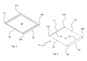
- the support tray 11 of the dripping pan 10, shown better in Figure 4 comprises a frame 12 with edges 13, 14, 15, 16 of quadrangular shape corresponding with that of the dripping pan which is supported with its perimeter on the edges 13-16 of the tray 11.
- the latter is made with metal wire shaped and welded, in particular with a metal external wire that forms a closed structure (such as a metal wire folded on itself and then welded for example in correspondence of the rear side 16) on which two further wires are applied through welding to form edges 13, 14.
- a metal external wire that forms a closed structure (such as a metal wire folded on itself and then welded for example in correspondence of the rear side 16) on which two further wires are applied through welding to form edges 13, 14.
- the frame 12 may also have a different shape.
- edges 18, 17 are spaced from the sides 13, 14 of the frame so as to allow the flowing of air in the space between them, when the dripping pan 10 is inserted in the muffle.
- the transfer of heat by convection between the space underlying and overlying the dripping pan 10 is thus allowed and it is avoided that the dripping pan 10, when in use inside the muffle 1, compromises a sufficiently uniform distribution of heat.
- edges 18, 17 are made by the same metal wire of the frame 12 and, according to the invention, are slightly lowered with respect to the same frame, to which they are joined up by means of the curved ends 17a, 17b and 18a, 18b, folded towards upwards.
- the rear ends 17b, 18b of the guide edges 17, 18 of the tray go abut against the stop projection 32 and 42 present on the deep-drawn guides 30, 40, when the tray is in a position advanced towards the mouth 8 of the muffle.
- the front ends 17a, 18a are located instead between the projection 32, 42 and the mouth of the muffle 8.
- the tray 11 is free to slide forward and backward along the guides 30, 40 until its rear ends 17b, 18b go abut against the protrusions 32, 42; for the insertion or extraction of the tray 11 it is tilted respect to the horizontal line so that the rear curved ends 17b, 18b can slide along the stop projection 32, 42, as seen in figure 5 .
- the front ends 17a, 18a are used to restore the planarity of the dripping pan 10.
- the front ends 17a, 18a and the rear ends 17b, 18b are mutually identical as shape and symmetrical as position, so the user does not have to worry about the insertion side of the tray 11 in the muffle 1.
- this operation is carried out advantageously without the dripping pan 10, which can be removed in advance by the tray 11.
- the dripping pan is kept always in horizontal condition during the movements along the deep-drawn guides 30, 40, so that its movement inside of the cooking chamber 2 of the muffle is completely safe.
- the guides 30', 40 ' realized with metallic wires applied to the walls 3 ', 4 ' of the muffle 1 ', on the sides 17 ' , 18 ' of the tray 11 ' the grooves 19 ' , 20 ' are provided, so that when the tray 11 ' is in the extracted condition (see fig. 6 ), they engage the anterior ends 30a ', 40a ' of the guides 30 ', 40 ', constituting the stopping means of the tray 11 '.
- the tray remains horizontal as well as the dripping pan 10 ' placed on it, which can then be easily grasped to remove it from, or put it on, the tray 11 ': thus no rotation of the dripping pan is needed to grab or move it with respect to the oven.
- this embodiment allows solving the technical problem underlying the invention.
- the dripping pan 10 ' always remains in the horizontal position when it is moved into the cooking chamber 2 of the muffle , being supported by the tray 11 ' that slides along the guides 30', 40' placed on the walls 3'4 '.
- the dripping pan 10 ' is easily lifted from the tray 11 ' grabbing it from the edges that stand on the frame 12 ', without having to perform rotations or other movements that do tilt it.
- the invention also applies to shelf or containers in general, having not only polygonal shapes (e.g. triangular, hexagonal, etc.) but also circular, elliptic or another complex configuration.
- the containers must have an edge that engages with the frame, similarly to that of the dripping pan in the previous examples; preferably such edge will be projecting with respect to the container in a manner similar to a flange, so as to rest on the frame.
- the tray will have, anyway, edges which engage in the guides, similar to the edges 17, 18, 17 ', 18 ' of the previous examples.
Landscapes
- Engineering & Computer Science (AREA)
- Chemical & Material Sciences (AREA)
- Combustion & Propulsion (AREA)
- Mechanical Engineering (AREA)
- General Engineering & Computer Science (AREA)
- Cookers (AREA)
- Baking, Grill, Roasting (AREA)
- Application Of Or Painting With Fluid Materials (AREA)
- Muffle Furnaces And Rotary Kilns (AREA)
Abstract
Description
- The present invention relates, in general, to a method for supporting in an oven, in particular but not exclusively of domestic type, containers for cooking, as dripping pans, oven pans, and similar.
- The oven can be of any kind, for example a separate appliance that is built in a furniture, or a part of a greater appliance as a kitchen; furthermore, the invention is independent of the type of heating chosen for the oven, whether it be electric or gas or electromagnetic (e.g. microwave) one.
- The invention is related to the muffle ovens, that are those with a body substantially parallelepiped or similar shape, which comprises a cavity or cooking chamber where it is introduced the food to be cooked or heated, frontally closed by a door; inside the cavity of the oven there are usually placed the support grids of the dishes, or, more generally, containers for food to be cooked, among which are known the dripping pans.
- Besides that as a container for food, a dripping pan for the oven can also be used to collect liquid from above in the case of cooking of food on a higher level, for example on a grid or on a roaster arranged in the oven above the dripping pan.
- These are trays, substantially, with a quadrangular shape that are placed on the grids present in the oven, in the case they have dimensions smaller than the dimensions of the muffle, or are directly supported by the side walls of the muffle; and different solutions are known for this purpose, essentially grouped into two categories.
- In the first, the side walls of the muffle of the oven have guides obtained by dimple of the metal sheet of the muffle, along which the edges of the dripping pan can slide; the dripping pan is thus supported directly by the dimples, being able to be extracted or inserted in the oven at different height levels determined by the guides which are formed on the walls of the muffle.
- An example of this type of oven is described in the Italian utility model application
MI95U 000399 - In the other category of known solutions, the guides inside the muffle are obtained by a frame made of metal wires or bars, which in practice have the same function of the dimples of the previous case; also in this solution the dripping pan can be placed in the cooking chamber at various heights depending on the number of guides formed in the frame and then applied to the side walls of the muffle.
- In the known ovens, irrespective of the fact that the guides for the dripping pans are realized by dimples or metal wires, it is expected that when the dripping pan is located at the mouth of the oven, to be extracted or inserted, it is kept in a stable condition projecting in part with respect to the mouth of the muffle, by stopping means: it mainly for purposes of security, in order to avoid that the dripping pan can fall or otherwise be pulled out inadvertently without be supported in flat condition.
- For example, in the ovens in which the guides of the dripping pan are formed by dimples, the stopping means can be obtained with deviations of the guides themselves with respect to their linear profile: in this way the rear edge of the dripping pan, on which some protuberances are arranged, goes in interference with these deviations so as to stop the sliding of the dripping pan when it is pulled out. For an example of this technical application, please refer to the utility model application mentioned above.
- An equivalent solution is obtained also for metal wire support structures, in which appropriate matching part are arranged; independently of the adopted solution (dimples or metal wires), for the extraction of the dripping pan from the oven and for the release of the dripping pan from the guides disposed on the side walls, it is necessary to make a rotation of the dripping pan with respect to its rear edge so as to tilt it of 10° - 20° with respect to the horizontal plane in which it lies normally.
- It is understandable that such a situation may cause the spill of liquids contained in the dripping pan in the moment in which it is pulled out from the oven, liquids which may have high temperature and which may spill inside the muffle (with consequent generation of fumes) or even on the door and in case on the hands of the person who uses the dripping pan (with consequent possible burn of him).
- Such situation implies evident dangers that would be desirable to avoid and it is therefore an object of the present invention to overcome this drawback of the current technical state of art.
- In other words, the technical problem underlying the present invention is to develop a method for the support of a container, such as a dripping pan or other, in an oven, which allows to handle it grasping during extraction or insertion in the chamber of the oven, without having necessarily to tilt as it happens in most known ovens considered above.
- The idea of a solution to this problem is to arrange a specific element of support which may be associated with the container, being it a dripping pan, a oven pan or other, and that be separated from it at the appropriate time, to handle the container freely without having to perform movements such as rotations, inclinations or otherwise.
- The features of the method of support according to the invention are specifically enunciated in the claims attached here; the invention also comprises an oven for the support of container whose features are also enunciated in the claims which will follow.
- These features, the advantages achieved by them will be more evident from the description which is then made of an embodiment of the invention, shown in the drawings here attached in an indicative and not limitative way, in which:
-
Figure 1 shows an isometric view of a muffle of a oven with a supported dripping pan, according to the invention; -
Figure 2 shows an enlarged detail of the previous figure; -
Figure 3 shows a perspective assembled view of the dripping pan associated to a support frame according to the invention; -
Figure 4 shows a support frame for a dripping pan, according to the invention; -
Figures 5 and 5a illustrate some support modes of a dripping pan according to the invention ; -
Figure 6 shows an isometric view of a muffle oven with a dripping pan supported in according to a particular embodiment of the invention; -
Figure 7 shows a support frame of the dripping pan of the previous figure; -
Figure 8 shows some support modes of a dripping pan ofFigures 6 and 7 . - With reference to the drawings listed above and in particular considering firstly the figures from 1 to 5, in them with the reference numeral 1 a muffle of an oven according to the invention is generally indicated.
- In the following description there will be only the references to the elements of the muffle necessary to the understanding of the invention, referring, for the other, to the muffles of the known ovens, such as those manufactured by the Applicant nowadays.
- The
muffle 1 has a cavity orcooking chamber 2 confined by a series of walls 3-7 made of sheet metal or similar; in particular, theside walls guides pan 10 at different heights with respect to thecavity 2 of the muffle. - Preferably the
guides protrusion tray 11 for supporting the drippingpan 10. - Further, in the same area, the
guides protrusions - The support tray 11 of the dripping
pan 10, shown better inFigure 4 , comprises aframe 12 withedges tray 11. - The latter is made with metal wire shaped and welded, in particular with a metal external wire that forms a closed structure (such as a metal wire folded on itself and then welded for example in correspondence of the rear side 16) on which two further wires are applied through welding to form
edges - In case the dripping pan has a different shape from the quadrangular one, the
frame 12 may also have a different shape. - Independently of that, along the edges of the
tray 11 that are located in correspondence of theside walls muffle 1, there areedges guides - Advantageously these
edges sides pan 10 is inserted in the muffle. The transfer of heat by convection between the space underlying and overlying the drippingpan 10 is thus allowed and it is avoided that the drippingpan 10, when in use inside themuffle 1, compromises a sufficiently uniform distribution of heat. - For this reason, the
edges frame 12 and, according to the invention, are slightly lowered with respect to the same frame, to which they are joined up by means of thecurved ends - As we can see in
Figure 2 , therear ends guide edges stop projection guides tray 11 is inserted in the deep-drawnguides front ends projection - Consequently the
tray 11 is free to slide forward and backward along theguides rear ends protrusions tray 11 it is tilted respect to the horizontal line so that the rearcurved ends stop projection figure 5 . Thefront ends pan 10. In practice, thefront ends rear ends tray 11 in themuffle 1. - According to the invention this operation is carried out advantageously without the dripping
pan 10, which can be removed in advance by thetray 11. - From the above description it can be understood as the way to support the dripping
pan 10 allows solving the technical problem at the base of the invention, as said above. In fact, when we have to grab the drippingpan 10 for introducing or extracting it from the oven, it can easily be placed on, or removed from, the support tray 11: this avoids tilting or otherwise releasing from the guides that support it as it is in the technical state of art above considered, eliminating completely the risks associated with these operations. - Furthermore it should be noted that the dripping pan is kept always in horizontal condition during the movements along the deep-drawn
guides cooking chamber 2 of the muffle is completely safe. - This also applies when the dripping
pan 10 protrudes out of the mouth of the muffle 8, because thetray 11 which supports it, remains in horizontal condition when itsends projections drawing guides - As above described, it also applies in the case of embodiments of the invention that differ from the previous one, such as those obtainable in the case where the guides, on the walls of the muffle along which the tray slides, are made with wire instead of being deep-drawing.
- This is the case of the embodiment shown in
Figures 6, 7 and8 , in which for convenience have been kept the same reference numbers of the elements structurally or functionally equivalent to those already seen, with the addition of an apex. - Thus, in this case being the guides 30', 40 ' realized with metallic wires applied to the walls 3 ', 4 ' of the muffle 1 ', on the sides 17 ' , 18 ' of the tray 11 ' the grooves 19 ' , 20 ' are provided, so that when the tray 11 ' is in the extracted condition (see
fig. 6 ), they engage the anterior ends 30a ', 40a ' of the guides 30 ', 40 ', constituting the stopping means of the tray 11 '. - The tray remains horizontal as well as the dripping pan 10 ' placed on it, which can then be easily grasped to remove it from, or put it on, the tray 11 ': thus no rotation of the dripping pan is needed to grab or move it with respect to the oven.
- In fact, such a movement is only required to release the tray from the guides 30 ', 40 ', but this can be easily done without the dripping pan; in this circumstance the folded shape of the
rear ends edges Figure 8 . - As easily understandable, also this embodiment allows solving the technical problem underlying the invention.
- In fact, the dripping pan 10 ' always remains in the horizontal position when it is moved into the
cooking chamber 2 of the muffle , being supported by the tray 11 ' that slides along the guides 30', 40' placed on the walls 3'4 '. - For the extraction from, or the introduction into, the cooking chamber 2 ' the dripping pan 10 ' is easily lifted from the tray 11 ' grabbing it from the edges that stand on the frame 12 ', without having to perform rotations or other movements that do tilt it.
- Of course on the basis of the teaching from the examples described above, it is possible to obtain further embodiments; it is already said, initially, that the invention applies to all the ovens that are compatible with the features, for example gas oven, electric oven or microwave oven.
- This is true also for ovens made as separate appliances or parts of appliances such as common household kitchen ranges.
- Anyway, all these embodiments take a part of the scope of the claims which follow.
- Relating to what it was said above, it should be noted that the invention is not limited only to the support of quadrangular dripping pan as shown in the examples.
- In fact, the invention also applies to shelf or containers in general, having not only polygonal shapes (e.g. triangular, hexagonal, etc.) but also circular, elliptic or another complex configuration.
- It's possible to think, for example, about backing pans made with ceramic material, or molds for cakes or similar, which are supported by a tray in which the
quadrilateral frame 12, 12' is replaced by a frame having a shape matching with that one of such containers. - The containers must have an edge that engages with the frame, similarly to that of the dripping pan in the previous examples; preferably such edge will be projecting with respect to the container in a manner similar to a flange, so as to rest on the frame.
- The tray will have, anyway, edges which engage in the guides, similar to the
edges - All these embodiments are part of the scope of the following claims.
Claims (16)
- A method for supporting a container (10; 10') in a muffle (1; 1') of an oven, comprising at least one pair of opposite walls (3, 4; 3', 4') in a cooking chamber (2; 2'), along which guides (30, 40; 30', 40') are provided for moving the container (10; 10'),
characterized in that it comprises the following steps:i) providing a tray (11; 11') slidable along the guides (30, 40; 30', 40'), comprising a frame (12; 12') for supporting the container (10; 10');ii) extracting the tray (11; 11') at least partly from the cooking chamber (2; 2') by sliding it along the guides (30, 40; 30', 40');iii) coupling the container (10; 10') to the frame (12; 12') of the tray (11; 11');iv) introducing the tray with the container (10; 10') into the cooking chamber (2; 2') by sliding it along the guides (30, 40; 30', 40'). - A method according to claim 1, wherein the sliding of the tray (11; 11') takes place in a substantially horizontal direction.
- A method according to claim 1 or 2, wherein the container is a dripping pan (10; 10').
- A method for extracting a container (10; 10') from a muffle (1; 1') of an oven, comprising at least one pair of opposite walls (3, 4; 3', 4') in a cooking chamber (2; 2'), along which guides (30, 40; 30', 40') are provided for moving the container (10; 10'),
characterized in that it comprises the following steps:i) providing a tray (11; 11') slidable along the guides (30, 40; 30', 40'), comprising a frame (12; 12') for supporting the container (10; 10');ii) extracting the tray (11; 11') at least partly from the cooking chamber (2; 2') by sliding it along the guides (30, 40; 30', 40');iii) removing the container (10; 10') from the frame (12; 12') of the tray (11; 11') and extracting it from the muffle. - Oven comprising a muffle (1) wherein there is arranged a food cooking chamber (2), at least one pair of opposite walls (3, 4; 3', 4') in the cooking chamber (2; 2'), along which guides (30, 40; 30', 40') are provided for moving containers (10; 10') to and from the cooking chamber,
characterized in that it comprises a tray (11; 11') movable along said guides (30, 40; 30', 40') and comprising a frame (12; 12') associable with a container (10; 10'); - Oven according to claim 5, wherein the tray comprises edges (17, 18; 17', 18') which slidably engage into the guides (30, 40; 30', 40') at a distance from the frame (12; 12').
- Oven according to claim 5 or 6, wherein the tray (11; 11') comprises at least one curved end (17b, 18b; 17b', 18b') which, in a condition wherein it protrudes at least partly from the cooking chamber (2; 2'), cooperates with stopping means (32, 42; 19', 20') of the guides (30, 40; 30', 40') to keep the tray (11; 11') in a stable and substantially horizontal condition.
- Oven according to any one of claims 5 to 7, wherein the tray (11; 11') is made of metal wire or the like.
- Oven according to any one of claims 5 to 8, wherein the frame (12; 12') has a polygonal, circular, elliptic or another complex configuration.
- Oven according to any one of claims 5 to 9, wherein the container (10; 10') is a dripping pan.
- Oven according to any one of claims 5 to 10, wherein the guides (30, 40) comprise dimples on the side walls (3, 4; 3', 4') of the muffle.
- Oven according to any one of claims 5 to 11, wherein the guides (30', 40') comprise metal wires applied to the side walls (3, 4) of the muffle.
- Dripping pan for ovens, characterized in that it is associated with a frame (12; 12') of a support tray (11; 11') to be inserted into the oven.
- Dripping pan according to claim 13, wherein the frame (12; 12') has smaller dimensions than the dripping pan, so that the edge of the latter will rest at least partly on the frame (12; 12').
- Oven tray (11; 11') slidable along guides (30, 40; 30', 40') provided on the walls (3-6; 3'-6') of a muffle (2; 2') of an oven, characterized in that it comprises a frame (12; 12') associable with a container (10; 10'), and edges (17, 18; 17', 18') to be slidably engaged into guides (30, 40; 30', 40') provided on the walls of the muffle (2; 2') at a distance from the frame (12; 12'), said frame (12; 12') being preferably polygonal.
- A tray according to claim 15, wherein the frame (12; 12') is polygonal.
Applications Claiming Priority (1)
| Application Number | Priority Date | Filing Date | Title |
|---|---|---|---|
| IT000167A ITTO20130167A1 (en) | 2013-02-28 | 2013-02-28 | METHOD OF SUPPORTING A CONTAINER IN AN OVEN AND OVEN FOR ITS IMPLEMENTATION |
Publications (1)
| Publication Number | Publication Date |
|---|---|
| EP2772694A1 true EP2772694A1 (en) | 2014-09-03 |
Family
ID=48366466
Family Applications (1)
| Application Number | Title | Priority Date | Filing Date |
|---|---|---|---|
| EP14155891.6A Withdrawn EP2772694A1 (en) | 2013-02-28 | 2014-02-20 | Method for supporting a container in an oven and oven for its implementation |
Country Status (3)
| Country | Link |
|---|---|
| EP (1) | EP2772694A1 (en) |
| IT (1) | ITTO20130167A1 (en) |
| RU (1) | RU2014107543A (en) |
Citations (4)
| Publication number | Priority date | Publication date | Assignee | Title |
|---|---|---|---|---|
| US2847932A (en) * | 1955-12-28 | 1958-08-19 | Gen Electric | Rotisserie rack |
| US2985096A (en) * | 1956-11-05 | 1961-05-23 | Whirlpool Co | Rotisserie apparatus |
| US20070137501A1 (en) * | 2005-12-19 | 2007-06-21 | Manuel Aaron J | Oven rack grilling apparatus and method of use thereof |
| US20090188915A1 (en) * | 2005-08-30 | 2009-07-30 | Kabushiki Kaisha Toshiba | Heating cooker |
-
2013
- 2013-02-28 IT IT000167A patent/ITTO20130167A1/en unknown
-
2014
- 2014-02-20 EP EP14155891.6A patent/EP2772694A1/en not_active Withdrawn
- 2014-02-27 RU RU2014107543/03A patent/RU2014107543A/en not_active Application Discontinuation
Patent Citations (4)
| Publication number | Priority date | Publication date | Assignee | Title |
|---|---|---|---|---|
| US2847932A (en) * | 1955-12-28 | 1958-08-19 | Gen Electric | Rotisserie rack |
| US2985096A (en) * | 1956-11-05 | 1961-05-23 | Whirlpool Co | Rotisserie apparatus |
| US20090188915A1 (en) * | 2005-08-30 | 2009-07-30 | Kabushiki Kaisha Toshiba | Heating cooker |
| US20070137501A1 (en) * | 2005-12-19 | 2007-06-21 | Manuel Aaron J | Oven rack grilling apparatus and method of use thereof |
Also Published As
| Publication number | Publication date |
|---|---|
| RU2014107543A (en) | 2015-09-10 |
| ITTO20130167A1 (en) | 2014-08-29 |
Similar Documents
| Publication | Publication Date | Title |
|---|---|---|
| JP5964271B2 (en) | Cooker | |
| JP6173526B2 (en) | Cooker | |
| EP1966542B1 (en) | An oven | |
| EP3217850B1 (en) | A smokeless grill pan | |
| KR101520498B1 (en) | Oven range including a rotational rack | |
| CN211582729U (en) | Grill assembly of barbecue electric appliance and barbecue electric appliance thereof | |
| KR20180025905A (en) | Cooking appliance protection device and method | |
| US8826898B2 (en) | Metal rack for an oven appliance | |
| US20130118475A1 (en) | Metal rack for an oven appliance | |
| US20190186756A1 (en) | Heating Appliance, in Particular Oven | |
| RU93502U1 (en) | ELECTRIC STOVE WITH A FRY CUPBOARD (OPTIONS) | |
| EP0747640A2 (en) | Oven for cooking foods | |
| CN115517015A (en) | Cooking appliance with conductive heating capability | |
| EP2772694A1 (en) | Method for supporting a container in an oven and oven for its implementation | |
| KR20110037387A (en) | Cooking tool that use as pan and roast plate and cover of cookware | |
| CN216932801U (en) | Baking tray assembly for cooking appliance and cooking appliance | |
| JP6001155B1 (en) | Skewers | |
| US10070753B2 (en) | Cooking chamber frame for a cooking appliance | |
| EP2149323B1 (en) | Barbecue | |
| US9565971B2 (en) | Food mounting assembly for a cooking appliance | |
| CN209018493U (en) | A kind of oven with grill | |
| EP2377441B1 (en) | Multifunctional Bread Maker | |
| CN211673845U (en) | Oven structure | |
| JP4000526B2 (en) | Cooker | |
| CN218500532U (en) | Cooking utensil |
Legal Events
| Date | Code | Title | Description |
|---|---|---|---|
| PUAI | Public reference made under article 153(3) epc to a published international application that has entered the european phase |
Free format text: ORIGINAL CODE: 0009012 |
|
| 17P | Request for examination filed |
Effective date: 20140220 |
|
| AK | Designated contracting states |
Kind code of ref document: A1 Designated state(s): AL AT BE BG CH CY CZ DE DK EE ES FI FR GB GR HR HU IE IS IT LI LT LU LV MC MK MT NL NO PL PT RO RS SE SI SK SM TR |
|
| AX | Request for extension of the european patent |
Extension state: BA ME |
|
| R17P | Request for examination filed (corrected) |
Effective date: 20150303 |
|
| RBV | Designated contracting states (corrected) |
Designated state(s): AL AT BE BG CH CY CZ DE DK EE ES FI FR GB GR HR HU IE IS IT LI LT LU LV MC MK MT NL NO PL PT RO RS SE SI SK SM TR |
|
| 17Q | First examination report despatched |
Effective date: 20160225 |
|
| RAP1 | Party data changed (applicant data changed or rights of an application transferred) |
Owner name: WHIRLPOOL EMEA S.P.A |
|
| STAA | Information on the status of an ep patent application or granted ep patent |
Free format text: STATUS: THE APPLICATION IS DEEMED TO BE WITHDRAWN |
|
| 18D | Application deemed to be withdrawn |
Effective date: 20170419 |