EP2772390A2 - Zwei oder drei Windturbinenschaufeln als eine Einheit - Google Patents
Zwei oder drei Windturbinenschaufeln als eine Einheit Download PDFInfo
- Publication number
- EP2772390A2 EP2772390A2 EP14157227.1A EP14157227A EP2772390A2 EP 2772390 A2 EP2772390 A2 EP 2772390A2 EP 14157227 A EP14157227 A EP 14157227A EP 2772390 A2 EP2772390 A2 EP 2772390A2
- Authority
- EP
- European Patent Office
- Prior art keywords
- wind turbine
- turbine blade
- blades
- transport unit
- blade
- Prior art date
- Legal status (The legal status is an assumption and is not a legal conclusion. Google has not performed a legal analysis and makes no representation as to the accuracy of the status listed.)
- Withdrawn
Links
Images


Classifications
-
- B—PERFORMING OPERATIONS; TRANSPORTING
- B60—VEHICLES IN GENERAL
- B60P—VEHICLES ADAPTED FOR LOAD TRANSPORTATION OR TO TRANSPORT, TO CARRY, OR TO COMPRISE SPECIAL LOADS OR OBJECTS
- B60P7/00—Securing or covering of load on vehicles
- B60P7/06—Securing of load
-
- B—PERFORMING OPERATIONS; TRANSPORTING
- B60—VEHICLES IN GENERAL
- B60P—VEHICLES ADAPTED FOR LOAD TRANSPORTATION OR TO TRANSPORT, TO CARRY, OR TO COMPRISE SPECIAL LOADS OR OBJECTS
- B60P3/00—Vehicles adapted to transport, to carry or to comprise special loads or objects
- B60P3/40—Vehicles adapted to transport, to carry or to comprise special loads or objects for carrying long loads, e.g. with separate wheeled load supporting elements
-
- F—MECHANICAL ENGINEERING; LIGHTING; HEATING; WEAPONS; BLASTING
- F03—MACHINES OR ENGINES FOR LIQUIDS; WIND, SPRING, OR WEIGHT MOTORS; PRODUCING MECHANICAL POWER OR A REACTIVE PROPULSIVE THRUST, NOT OTHERWISE PROVIDED FOR
- F03D—WIND MOTORS
- F03D13/00—Assembly, mounting or commissioning of wind motors; Arrangements specially adapted for transporting wind motor components
- F03D13/40—Arrangements or methods specially adapted for transporting wind motor components
-
- Y—GENERAL TAGGING OF NEW TECHNOLOGICAL DEVELOPMENTS; GENERAL TAGGING OF CROSS-SECTIONAL TECHNOLOGIES SPANNING OVER SEVERAL SECTIONS OF THE IPC; TECHNICAL SUBJECTS COVERED BY FORMER USPC CROSS-REFERENCE ART COLLECTIONS [XRACs] AND DIGESTS
- Y02—TECHNOLOGIES OR APPLICATIONS FOR MITIGATION OR ADAPTATION AGAINST CLIMATE CHANGE
- Y02E—REDUCTION OF GREENHOUSE GAS [GHG] EMISSIONS, RELATED TO ENERGY GENERATION, TRANSMISSION OR DISTRIBUTION
- Y02E10/00—Energy generation through renewable energy sources
- Y02E10/70—Wind energy
- Y02E10/72—Wind turbines with rotation axis in wind direction
Definitions
- the present invention relates to a method for transporting two or three pre-bend wind turbine blades for a wind turbine, said wind turbine blades each having a length extending from a first end, e.g. a root end describing a first end plane, to a second end, e.g. a tip end, where said length is at least 35 metres, said wind turbine blades each comprising a central longitudinal axis extending perpendicular from said first end plane and towards said second end, said wind turbine blade further comprises an aerodynamically shaped body comprising a pressure side, a suction side, a leading edge and a trailing edge.
- the method according to the invention for transporting two or three wind turbine blades comprises at least the following steps:
- the invention further relates to a wind turbine blade transport unit comprising two or three pre-bend wind turbine blades, said wind turbine blades each having a length extending from a first end, e.g. a root end describing a first end plane, to a second end, e.g. a tip end, where said length is at least 35 metres, said wind turbine blades each comprising a central longitudinal axis extending perpendicular from said first end plane and towards said second end, said wind turbine blade further comprises an aerodynamically shaped body comprising a pressure side, a suction side, a leading edge and a trailing edge.
- a wind turbine blade transport unit comprises a first end support frame, said first end support frame comprising means for fixating the first end of each wind turbine rotor blade against rotational movement about the longitudinal axis, against longitudinal movement and against angular movement of the first end in relation to said first end support frame.
- Wind turbine blades with this feature are commonly known as pre-bend wind turbine blades, as the unloaded blade is curved.
- a pre-bend blade during use When a pre-bend blade during use is loaded, it will be straightened, instead of swept back, and this will allow the rotor to be arranged closer to the tower and still maintain a reasonably tip to tower distance.
- the tip to tower distance is actually the main advantage of the pre-bend blades, and over time this has more or less become the standard for modem and large wind turbine blades. Especially when talking about wind turbine blades having a length of more than 35, 40, 45 or even more than 50 metres.
- pre-bend blades are however very clear when it comes to transportation, especially by road. As the blades no longer are as straight as they used to be, they take up considerably more space in both the width direction and in the height direction. This has been handled in various manners, but one very used method has been to transport such pre-bend wind turbine blades one by one using a truck with a flatbed trailer and a following safety car.
- flatbed trailer is to be understood as a general term comprising the various types of trailers having a more or less flat carrier surface including Drop Deck, Double Drop Deck, Step Deck and other types of trailers.
- the blades are transported one by one by a truck on a flatbed trailer, and if the blades have to be shipped, they will be transported to the harbour using trucks as described, and the blades will be hoisted onto the ship and secured to the deck one by one.
- the wind turbine blades will typically be fitted with a frame or a foot at the root end and further there will typically be some kind of support structure at the outermost portion of the blade e.g. at 2/3 of the blade length when measured from the root end.
- the invention relates to a method for transporting two or three pre-bend wind turbine blades for a wind turbine, said wind turbine blades each having a length extending from a first end, e.g. a root end describing a first end plane, to a second end, e.g. a tip end, where said length is at least 35 metres, said wind turbine blades each comprising a central longitudinal axis extending perpendicular from said first end plane and towards said second end, said wind turbine blade further comprises an aerodynamically shaped body comprising a pressure side, a suction side, a leading edge and a trailing edge wherein said method for transporting two or three wind turbine blades comprises at least the following steps:
- the invention also relates to a wind turbine blade transport unit comprising two or three pre-bend wind turbine blades, said wind turbine blades each having a length extending from a first end, e.g. a root end describing a first end plane, to a second end, e.g.
- said wind turbine blades each comprising a central longitudinal axis extending perpendicular from said first end plane and towards said second end, said wind turbine blade further comprises an aerodynamically shaped body comprising a pressure side, a suction side, a leading edge and a trailing edge wherein said transport unit comprising two or three wind turbine blades further comprises a first end support frame, said first end support frame comprising means for fixating the first end of each wind turbine rotor blade against rotational movement about the longitudinal axis, against longitudinal movement and against angular movement of the first end in relation to said first end support frame.
- the method according to the invention for transporting two or three pre-bend wind turbine blades further includes the following steps:
- the wind turbine blades By arranging the wind turbine blades with the root end/first end located at the same end of a unit comprising two or three pre-bend blades it is possible to have the main weight of a transport unit concentrated at that end.
- This will allow for use of a standard flat bed trailer, where the blades and the transport unit can be arranged with the root end at the front end of a trailer and with at least a part of the blades extending from the rear end of said trailer, i.e. in a cantilever style. It is thus not necessary to use a flat bed trailer or the like capable of carrying or even supporting the blades along the complete length.
- the trailer used can thus be considerably shorter than the blades and thus also a lot easier to manoeuvre on ordinary roads without having too much trouble as the wheelbase of course is shorter that by conventional transports where the wind turbine blades are supported along practically all their length.
- the two or three wind turbine blades are arranged in an individual angular position about the individual central longitudinal axis of each wind turbine blade in relation to the one or two other blades.
- By arranging the blades in an individual angel about the longitudinal axis it is possible to arrange each blade in an optimal position in order to merge or braid the pre-bend blades and thus obtain a more compact transport unit. This will be discussed further below and examples will be given.
- first end/first end plane of each of the two or three wind turbine blades in an individual angular position in relation to a common plane.
- the individual blades more precisely the central longitudinal axis
- the wind turbine blades After having arranged the wind turbine blades in an attractive position they will be fixed in that specific position in relation to the one or two other wind turbine blades as one single transport unit. Such a fixation will typically be performed by securing the individual blades to a common frame, where said frame comprises means for fastening the blades in both the longitudinal and the rotational direction. This can e.g. be done by interacting with means in the root end of the blades for fastening said blades at a hub of a wind turbine.
- the root ends will typically comprise a number of steel bushings with an internal tread for bolts or other means for connection to a hub, to a pitch system or to other means on the turbine. Said means are constructed to carry the weight of the blades and also the loads from the wind, and they will most certainly also be capable of holding the blade in position during transport.
- the frame to which they are fixated can have a flange or receiving means with an angle that is specific to the individual blades in order to have a full support of the blade at the root end/first end and the plane described by said end.
- the first end of two or three blades can be arranged at mainly the same lengthwise position, or alternatively within 0 to 8 metres, or 0 to 5, or 0 to 3 or within 0 to 1 metres, where one or more of said blades are arranged offset in a longitudinal direction in relation to one or more other blades, but still having the first ends in or near one end of a unit and the second ends in or near another end of a unit.
- By arranging the root ends of the blades in an offset position it becomes possible to optimise the transport unit according to flatbed trailers of the Drop Deck and Double Drop Deck types, where there is a difference in the height of the carrier surface of the trailer at the front end and also at the back end when it comes to the Double Drop Deck type.
- An example of a transport unit comprising three wind turbine blades on a Drop Deck trailer will be seen in the figures.
- said transport unit comprising two or three pre-bend wind turbine blades further comprises a first end support frame, said first end support frame comprising means for fixating the first end of each wind turbine rotor blade against rotational movement about the longitudinal axis, against longitudinal movement and against angular movement of the first end in relation to said first end support frame.
- a method for transporting two or three pre-bend wind turbine blades according to the invention further comprises fixating said first end of each wind turbine blade to a first end support frame, where each blade is fixed against:
- the invention comprises that said wind turbine blade is a pre-bend wind turbine blade. Especially transportation of pre-bend blades has become more and more difficult due to the increasing length of the blades, but also due to wider blades and even more pre-bending than the earlier and shorter blades had.
- the two blades are arranged more or less having an internal rotational relationship of about 90 degrees (could also be between approximately 60 to 120, 70 to 110 or 80 to 100 degrees), which will allow for the blades to be positioned relatively close to each other and still leave space and room for the pre-bend parts not to get in unnecessary contact.
- a method according to the invention can also include the following step:
- the method according to the invention can also comprise arranging a support structure at a distance from the first end of the wind turbine blades, where said support structure comprise one piece or several pieces, arranged between and possible also around the two to three blades in a transport unit.
- Said structure can e.g. be made from a foam material such as polystyrene, which will support the blades and also prevent the blades from getting into damaging contact with each other.
- the structure can be made from other materials as well e.g. wood, and also from combinations of e.g. foam and wood.
- One object to bear in mind is that the structure needs to have a reasonable weight.
- a wind turbine blade transport unit may comprise a first end support frame, where such a support frame can comprise a structure, e.g. a lattice structure, and at least one fastening bracket per wind turbine blade, said structure and fastening brackets are arranged for engaging with fastening means at the first end of each wind turbine blade, e.g. with fastening means for fastening said wind turbine blade to the wind turbine.
- a structure e.g. a lattice structure
- fastening brackets are arranged for engaging with fastening means at the first end of each wind turbine blade, e.g. with fastening means for fastening said wind turbine blade to the wind turbine.
- This can as mentioned be steel bushings or inserts in the root end area of the blades that is used as they are present and dimensioned to overcome operational loads higher than the loads that will occur during transport.
- said means on said first end support frame of the transport unit comprises a structure, said structure comprising at least one set of holes for each wind turbine blade, where said holes are arranged for aligning with fastening means at the first end of each wind turbine blade, e.g. with fastening means for fastening said wind turbine blade to the wind turbine.
- the support frame can have a number of holes arranged to be aligned with corresponding holes in the root end of the blade and in which a number of bolts can be installed to secure the blade in a specific rotational, longitudinal and angular (angle of the central longitudinal axis) position.
- said first end support frame comprises one portion for each wind turbine blade to be arranged in said wind turbine blade transport unit, where such a portion is arranged with an individual angle in relation to at least one further portions on the same first end support frame. This allows for the individual blades to be arranged with a different or individual angle of the longitudinal axis.
- a wind turbine blade transport unit has an overall width of 4700 millimetres or less and an overall height of 4800 millimetres or less, where the height is measured from a road level and includes a trailer, e.g. a flat bed trailer or another kind of carrier.
- a trailer e.g. a flat bed trailer or another kind of carrier.
- a blade transport unit as described above is advantageous in different countries, where a cost-effective and time optimised solution is needed.
- three blades for a typical wind turbine or two blades for e.g. a partial pitch wind turbine can be transported as a single unit using standard transport equipment for road transport.
- Such a transport unit and a method according to the invention are indeed suitable for the Chinese wind turbine marked.
- a standard trailer having a length of e.g. 27 metres can without any problems be used for transporting a transport unit according to the invention comprising three wind turbine blades each having a length of 35 to 40 metres or even longer.
- the first end being the root end of the blades is arranged at the front end of the trailer, and in the area near the rear end of the trailer the blades are supported by suitable means and will stretch as a cantilever from the trailer.
- the free end being the tip end of the blades is much lighter than the root end, transport is problem-free.
- a wind turbine blade transport unit may comprises a support structure, said support structure comprising one or more surfaces corresponding to the surface of one, two or three wind turbine blades, said surfaces being arranged in a specific pattern corresponding to the individual position of one or more blades arranged in a transport unit.
- Such a support structure/means can be arranged at one or more areas along the length of the blades for supporting the blades.
- Such means can e.g. be made from polystyrene or another kind of support material that can be arranged in contact with the surface of the blades.
- the support means can be made in one piece or in one piece per blade and can comprise a part that is embedded between the blades, but also a part facing outwards from the blade where a transport strap can be used to fixate the respective blades to each other via the support means.
- the invention can be described as a virtual box surrounding the two or three wind turbine blades, where said virtual box together with the trailer has a size that is allowable to transport by road in the specific location.
- Position number list 1 Wind turbine 2 Tower 3 Foundation 4 Nacelle 5 Hub 6 Wind turbine blade 7 First end of blade/root end of blade 8 Second end of blade/tip end of blade 9 Leading edge 10 Trailing edge 11 Truck 12 Trailer 13 Transport unit 14 Support frame 15 Fastening strap 16 Root flange with boltholes 17 Boltholes/fastening means 18 Central longitudinal axis 19 Fastening bracket 20 Suction side 21 Pressure side 22 First direction 23 First plane 24 B - width 25 H - height
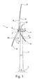
- a typical wind turbine 1 comprising a tower 2 installed at a foundation 3.
- a nacelle 4 comprising e.g. a gearbox, a generator and other components is seen.
- a shaft for carrying a rotor comprising a hub 5 and three wind turbine blades 6.
- the blades 6 are arranged at the hub 5 at a first end 7 called the root end of the blade 6.
- the second end 8 of the blades 6 constitutes a tip end.
- the wind turbine blades 6 all comprise an airfoil shaped body comprising a leading edge 9 and a trailing edge 10 extending along the wind turbine blade 6.
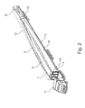
- Fig. 2 shows a truck 11 with a flatbed trailer 12 carrying three wind turbine blades 6 arranged in a first configuration in a transport unit 13.
- the transport unit 13 constitutes a virtual box 13 with all the blades 6 having the first end 7 at one end and with the second end 8 of the blades 6 at the other end.
- the blades 6 are fastened to a support frame 14, and near the second end 8 the blades 6 are fixated by a fastening strap 15 which holds the transport unit 13 in place on the trailer 12.
- the fastening strap 15 can be arranged on a support structure e.g. a polystyrene foam block, that is arranged between the blades 6 and thus supports the blades 6 and holds them in place.
- Fig. 3 also shows a truck 11, but here seen with a Drop Deck trailer 12, where the two lower wind turbine blades 6', 6" are arranged with the first end 7', 7" near the step on the trailer deck and with the third blade 6"' having the first end 7"' closer to the cabin of the truck 11.
- a transport unit 13 can be advantageous depending on the specific shape of the blades 6.
- fig. 3 shows that the transport unit 13 is longer than the trailer 12 and that the blades are fixated to the trailer 12 with a fastening strap 15 and interconnected near the second end 8 of the blade 6 with another fastening strap 15.
- the transport unit 13 is seen with one end extending from the rear end of the trailer 12 in a cantilever style, which makes the transport easier to manoeuvre on ordinary roads when comparing to the transport as seen in fig. 2 .
- a support structure e.g. a block of foam can be arranged and used to support the blades 6 and the transport unit 13 in general.
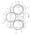
- Fig. 4 shows three wind turbine blades 6 fixated to a first end support frame 14.
- the first end 7 of the blades 6 comprises a root flange 16 with boltholes 17 intended for fastening the blade 6 to the hub 5 of a wind turbine 1.
- the central longitudinal axis 18 of the blades 6 is defined as an axis in the centre of the root flange 16, where the axis extends perpendicular to said root flange 16.
- the blades 6 are fastened to the support frame 14 by means of fastening brackets 19 that via not seen bolts are fixated around the lattice structure of the support frame 14 to the boltholes 17 in the root flange 16.
- the first wind turbine blade 6' is arranged with the suction side 20 facing in a first direction 22 towards a first plane 23, said first plane 23 being horizontal in this specific situation.
- the second wind turbine blade 6" is arranged with the leading edge 9 facing in the first direction 22 towards the first plane 23, both the first 6' and second 6" wind turbine blade being arranged side by side.
- the first blade 6' having the suction side 20 facing down, the pressure side 21 facing up and consequently the leading edge 9 facing right and the trailing edge 10 facing left.
- the second blade 6" has the suction side 20 facing left, the pressure side 21 facing right and consequently the leading edge 9 facing down and the trailing edge 10 facing up.
- the two blades 6', 6" are arranged more or less having an internal rotational relationship of about 90 degrees (could also be between approximately 60 to 120, 70 to 110 or 80 to 100 degrees), which will allow for the blades 6', 6" to be positioned relatively close to each other and still leave space and room for the pre-bend parts not to get in unnecessary contact.
- the third wind turbine blade 6"' is arranged with the leading edge 9 facing in the first direction 22 towards the first plane 23, where said third wind turbine blade 6"' is arranged offset in relation to the first 6' and second 6" wind turbine blade and said first plane 23.
- the third wind turbine blade 6"' is arranged at a position above and between the first 6' and second 6" wind turbine blade.
- the third blade 6"' is more or less placed in the same manner as the second blade 6", i.e. with 0 or only a relatively few degrees difference, e.g. 5, 10, 15 or 20 degrees difference, but preferably with the longitudinal axis 18 in an angled position to allow the second end 8 of the blade 6"' to be merged/braided with the second ends 8 of the first 6' and second 6" blade ends in order to optimise the size of the transport unit 13. This is seen in fig. 6 .
- Fig. 5 shows the root end 7 of three wind turbine blades 6 in the same arrangement as seen in fig. 4 , where the width 24 of the transport unit 13 is illustrated with a B and the height 25 of the transport unit 13 is illustrated with H.
- Fig. 6 shows the second end 8 of three wind turbine blades 6 in the same arrangement as seen in fig. 4 and 5 .
- the individual blades 6 need to be arranged in a very specific manner in order to prevent them from interfering with each other.
- the longitudinal axis 18 of the first 6' and the second 6" blade the longitudinal axes are mainly in the same direction, but the longitudinal axis 18 of the third blade 6"' is pointing downwards in order to arrange the third blade end 8"' merged or braided with the first 8' and second blade 8" ends as depicted in fig. 6 .
- the third blade 6"' is more or less placed rotated 90 degrees to the second blade 6" (could also be between approximately 60 to 120, 70 to 110 or 80 to 100 degrees), and possibly with the longitudinal axis 18 in an angled position (up or down) to allow the tip 8"' of the blade 6"' to be merged/braided with the two other tip ends 8', 8" in order to optimise the size of the transport unit 13.
- Fig. 8 shows the tip end 8 of three wind turbine blades 6 in the same arrangement as seen in fig. 7 . Also here it becomes visible that the individual blades 6 need to be arranged in a very specific manner in order to prevent them from interfering with each other. With reference to the longitudinal axis 18 of the first 6', the second 6" and third 6"' blade the longitudinal axes are mainly in the same direction having mainly parallel longitudinal axes 18.
Landscapes
- Engineering & Computer Science (AREA)
- Mechanical Engineering (AREA)
- Transportation (AREA)
- Health & Medical Sciences (AREA)
- Public Health (AREA)
- Life Sciences & Earth Sciences (AREA)
- Sustainable Development (AREA)
- Sustainable Energy (AREA)
- Chemical & Material Sciences (AREA)
- Combustion & Propulsion (AREA)
- General Engineering & Computer Science (AREA)
- Wind Motors (AREA)
Applications Claiming Priority (1)
| Application Number | Priority Date | Filing Date | Title |
|---|---|---|---|
| DK201370122A DK177951B1 (en) | 2013-03-01 | 2013-03-01 | Two or three wind turbine blades as one unit |
Publications (2)
| Publication Number | Publication Date |
|---|---|
| EP2772390A2 true EP2772390A2 (de) | 2014-09-03 |
| EP2772390A3 EP2772390A3 (de) | 2018-01-17 |
Family
ID=50159174
Family Applications (1)
| Application Number | Title | Priority Date | Filing Date |
|---|---|---|---|
| EP14157227.1A Withdrawn EP2772390A3 (de) | 2013-03-01 | 2014-02-28 | Zwei oder drei Windturbinenschaufeln als eine Einheit |
Country Status (5)
| Country | Link |
|---|---|
| US (1) | US9168858B2 (de) |
| EP (1) | EP2772390A3 (de) |
| CN (1) | CN104018994B (de) |
| CA (1) | CA2844281C (de) |
| DK (1) | DK177951B1 (de) |
Cited By (1)
| Publication number | Priority date | Publication date | Assignee | Title |
|---|---|---|---|---|
| EP3620651A4 (de) * | 2018-06-28 | 2020-07-29 | Jiangsu Goldwind Science & Technology Co., Ltd. | Klingentransporthalter |
Families Citing this family (7)
| Publication number | Priority date | Publication date | Assignee | Title |
|---|---|---|---|---|
| CN109131030B (zh) * | 2016-11-07 | 2020-11-06 | 安徽硕日光电科技有限公司 | 电力线杆自动装卸运输车 |
| US10435913B2 (en) * | 2016-11-23 | 2019-10-08 | Tindall Corporation | Method and apparatus for constructing a concrete structure in stages |
| IL305685A (en) * | 2021-03-10 | 2023-11-01 | Zsm Holdings Llc | Systems and methods for assembling large cargo and loading it onto a cargo aircraft |
| CN113027694B (zh) * | 2021-03-25 | 2022-08-30 | 中材科技风电叶片股份有限公司 | 转运机构、叶根移送小车、叶尖移送小车及叶片转运系统 |
| CN113638849B (zh) * | 2021-10-13 | 2021-12-07 | 南通艾郎风电科技发展有限公司 | 一种用于风力叶片输送转运的安装机构 |
| CN113636289B (zh) * | 2021-10-13 | 2021-12-17 | 南通艾郎风电科技发展有限公司 | 一种用于风力叶片生产加工的输送装置 |
| CN113685321B (zh) * | 2021-10-26 | 2021-12-28 | 南通海舟船舶设备有限公司 | 一种海上风机塔架运输设备 |
Family Cites Families (10)
| Publication number | Priority date | Publication date | Assignee | Title |
|---|---|---|---|---|
| BRPI0405546F1 (pt) * | 2004-12-10 | 2016-03-22 | Tecsis Tecnologia E Sist S Avançados Ltda | desenvolvimento em conjunto de estruturas para manuseio, transporte e armazenamento de pás para rotores de aerogeradores |
| BRPI0602764B1 (pt) * | 2006-07-04 | 2016-03-22 | Tecsis Tecnologia E Sist S Avançados Ltda | método e embalagem para transporte de pás de aerogeradores |
| US7713007B2 (en) * | 2007-05-31 | 2010-05-11 | General Electric Company | Method and apparatus for containing, storing and/or transporting curved wind turbine rotor blades |
| CN101648539A (zh) * | 2008-10-31 | 2010-02-17 | 维斯塔斯风力系统有限公司 | 用于运输转子叶片的运输系统 |
| BRPI0823414A2 (pt) * | 2008-12-19 | 2015-10-06 | Tecsis Tecnologia E Sist S Avançados Ltda | método para embalar e sistemas de embalagem para três pás de aerogeradores |
| WO2010105626A2 (en) * | 2009-03-18 | 2010-09-23 | Vestas Wind Systems A/S | A wind turbine blade transport casing |
| US8342491B2 (en) * | 2009-04-01 | 2013-01-01 | Vestas Wind Systems A/S | Transport system for transportation of a spar |
| US8172493B2 (en) * | 2009-05-04 | 2012-05-08 | General Electric Company | Apparatus and method for transporting and aligning wind turbine rotor blade |
| US8511921B2 (en) * | 2009-12-07 | 2013-08-20 | General Electric Company | System and method for arranging wind turbine blades |
| US8322954B2 (en) * | 2010-07-26 | 2012-12-04 | General Electric Company | Turbine component transportation system and method |
-
2013
- 2013-03-01 DK DK201370122A patent/DK177951B1/da not_active IP Right Cessation
-
2014
- 2014-02-28 CN CN201410073644.3A patent/CN104018994B/zh active Active
- 2014-02-28 US US14/193,303 patent/US9168858B2/en not_active Expired - Fee Related
- 2014-02-28 EP EP14157227.1A patent/EP2772390A3/de not_active Withdrawn
- 2014-02-28 CA CA2844281A patent/CA2844281C/en not_active Expired - Fee Related
Non-Patent Citations (1)
| Title |
|---|
| None * |
Cited By (2)
| Publication number | Priority date | Publication date | Assignee | Title |
|---|---|---|---|---|
| EP3620651A4 (de) * | 2018-06-28 | 2020-07-29 | Jiangsu Goldwind Science & Technology Co., Ltd. | Klingentransporthalter |
| US11486363B2 (en) | 2018-06-28 | 2022-11-01 | Jiangsu Goldwind Science & Technology Co., Ltd. | Blade transport holder |
Also Published As
| Publication number | Publication date |
|---|---|
| US20140248112A1 (en) | 2014-09-04 |
| DK177951B1 (en) | 2015-02-02 |
| CA2844281A1 (en) | 2014-09-01 |
| CA2844281C (en) | 2015-08-25 |
| DK201370122A (en) | 2014-09-02 |
| CN104018994A (zh) | 2014-09-03 |
| US9168858B2 (en) | 2015-10-27 |
| EP2772390A3 (de) | 2018-01-17 |
| CN104018994B (zh) | 2016-09-28 |
Similar Documents
| Publication | Publication Date | Title |
|---|---|---|
| US9168858B2 (en) | Two or three wind turbine blades as one unit | |
| EP1849719B1 (de) | Transporteinheit für ein Rotorblatt einer Windenergieanlage | |
| US10871148B2 (en) | Modular system for transporting wind turbine blades | |
| EP1997681B1 (de) | Verfahren und Vorrichtung zum Aufnehmen, Speichern und/oder Transportieren von gebogenen Rotorblättern | |
| US8622670B2 (en) | Three aerogenerator blades packing system (packing method and packing system for three aerogenerator blades) | |
| US8511921B2 (en) | System and method for arranging wind turbine blades | |
| US7670090B1 (en) | Wind turbine blade transportation system and method | |
| US10066606B2 (en) | Stacking wind turbine blades for sea transport | |
| CA2734395C (en) | System for transportation of blades on railcars | |
| US20150369209A1 (en) | Rotor blade transportation system | |
| US20110135417A1 (en) | System and method for arranging wind turbine blades | |
| CN103302645B (zh) | 机舱架以及用于组装和测试风力涡轮机机舱的方法 | |
| CN109642546B (zh) | 用于风力涡轮机叶片的运输和存储系统 | |
| WO2023117014A1 (en) | Transport or storage arrangement of a split wind turbine blade | |
| EP2497686A1 (de) | Transportverfahren für eine Windturbinenschaufel |
Legal Events
| Date | Code | Title | Description |
|---|---|---|---|
| PUAI | Public reference made under article 153(3) epc to a published international application that has entered the european phase |
Free format text: ORIGINAL CODE: 0009012 |
|
| 17P | Request for examination filed |
Effective date: 20140228 |
|
| AK | Designated contracting states |
Kind code of ref document: A2 Designated state(s): AL AT BE BG CH CY CZ DE DK EE ES FI FR GB GR HR HU IE IS IT LI LT LU LV MC MK MT NL NO PL PT RO RS SE SI SK SM TR |
|
| AX | Request for extension of the european patent |
Extension state: BA ME |
|
| PUAL | Search report despatched |
Free format text: ORIGINAL CODE: 0009013 |
|
| AK | Designated contracting states |
Kind code of ref document: A3 Designated state(s): AL AT BE BG CH CY CZ DE DK EE ES FI FR GB GR HR HU IE IS IT LI LT LU LV MC MK MT NL NO PL PT RO RS SE SI SK SM TR |
|
| AX | Request for extension of the european patent |
Extension state: BA ME |
|
| RIC1 | Information provided on ipc code assigned before grant |
Ipc: B60P 3/40 20060101AFI20171208BHEP |
|
| RAP1 | Party data changed (applicant data changed or rights of an application transferred) |
Owner name: ENVISION ENERGY (DENMARK) APS |
|
| R17P | Request for examination filed (corrected) |
Effective date: 20180703 |
|
| RBV | Designated contracting states (corrected) |
Designated state(s): AL AT BE BG CH CY CZ DE DK EE ES FI FR GB GR HR HU IE IS IT LI LT LU LV MC MK MT NL NO PL PT RO RS SE SI SK SM TR |
|
| GRAP | Despatch of communication of intention to grant a patent |
Free format text: ORIGINAL CODE: EPIDOSNIGR1 |
|
| INTG | Intention to grant announced |
Effective date: 20181106 |
|
| STAA | Information on the status of an ep patent application or granted ep patent |
Free format text: STATUS: THE APPLICATION IS DEEMED TO BE WITHDRAWN |
|
| 18D | Application deemed to be withdrawn |
Effective date: 20190319 |