EP2772371A1 - Trailer vehicle with a tandem axle - Google Patents
Trailer vehicle with a tandem axle Download PDFInfo
- Publication number
- EP2772371A1 EP2772371A1 EP14401026.1A EP14401026A EP2772371A1 EP 2772371 A1 EP2772371 A1 EP 2772371A1 EP 14401026 A EP14401026 A EP 14401026A EP 2772371 A1 EP2772371 A1 EP 2772371A1
- Authority
- EP
- European Patent Office
- Prior art keywords
- suspension
- shut
- valve
- cylinder
- tandem axle
- Prior art date
- Legal status (The legal status is an assumption and is not a legal conclusion. Google has not performed a legal analysis and makes no representation as to the accuracy of the status listed.)
- Granted
Links
- 239000000725 suspension Substances 0.000 claims abstract description 70
- 238000006073 displacement reaction Methods 0.000 claims abstract description 46
- 230000008878 coupling Effects 0.000 claims description 4
- 238000010168 coupling process Methods 0.000 claims description 4
- 238000005859 coupling reaction Methods 0.000 claims description 4
- 230000000903 blocking effect Effects 0.000 description 2
- 230000003247 decreasing effect Effects 0.000 description 1
- 230000000694 effects Effects 0.000 description 1
- 239000000463 material Substances 0.000 description 1
- 239000000575 pesticide Substances 0.000 description 1
- 239000007921 spray Substances 0.000 description 1
Images


Classifications
-
- B—PERFORMING OPERATIONS; TRANSPORTING
- B60—VEHICLES IN GENERAL
- B60G—VEHICLE SUSPENSION ARRANGEMENTS
- B60G5/00—Resilient suspensions for a set of tandem wheels or axles having interrelated movements
-
- B—PERFORMING OPERATIONS; TRANSPORTING
- B60—VEHICLES IN GENERAL
- B60G—VEHICLE SUSPENSION ARRANGEMENTS
- B60G17/00—Resilient suspensions having means for adjusting the spring or vibration-damper characteristics, for regulating the distance between a supporting surface and a sprung part of vehicle or for locking suspension during use to meet varying vehicular or surface conditions, e.g. due to speed or load
- B60G17/02—Spring characteristics, e.g. mechanical springs and mechanical adjusting means
- B60G17/04—Spring characteristics, e.g. mechanical springs and mechanical adjusting means fluid spring characteristics
- B60G17/056—Regulating distributors or valves for hydropneumatic systems
-
- B—PERFORMING OPERATIONS; TRANSPORTING
- B60—VEHICLES IN GENERAL
- B60G—VEHICLE SUSPENSION ARRANGEMENTS
- B60G21/00—Interconnection systems for two or more resiliently-suspended wheels, e.g. for stabilising a vehicle body with respect to acceleration, deceleration or centrifugal forces
- B60G21/02—Interconnection systems for two or more resiliently-suspended wheels, e.g. for stabilising a vehicle body with respect to acceleration, deceleration or centrifugal forces permanently interconnected
- B60G21/06—Interconnection systems for two or more resiliently-suspended wheels, e.g. for stabilising a vehicle body with respect to acceleration, deceleration or centrifugal forces permanently interconnected fluid
- B60G21/067—Interconnection systems for two or more resiliently-suspended wheels, e.g. for stabilising a vehicle body with respect to acceleration, deceleration or centrifugal forces permanently interconnected fluid between wheels on different axles on the same side of the vehicle, i.e. the left or the right side
-
- B—PERFORMING OPERATIONS; TRANSPORTING
- B60—VEHICLES IN GENERAL
- B60G—VEHICLE SUSPENSION ARRANGEMENTS
- B60G21/00—Interconnection systems for two or more resiliently-suspended wheels, e.g. for stabilising a vehicle body with respect to acceleration, deceleration or centrifugal forces
- B60G21/02—Interconnection systems for two or more resiliently-suspended wheels, e.g. for stabilising a vehicle body with respect to acceleration, deceleration or centrifugal forces permanently interconnected
- B60G21/06—Interconnection systems for two or more resiliently-suspended wheels, e.g. for stabilising a vehicle body with respect to acceleration, deceleration or centrifugal forces permanently interconnected fluid
- B60G21/073—Interconnection systems for two or more resiliently-suspended wheels, e.g. for stabilising a vehicle body with respect to acceleration, deceleration or centrifugal forces permanently interconnected fluid between wheels on the same axle but on different sides of the vehicle, i.e. the left and right wheel suspensions being interconnected
-
- B—PERFORMING OPERATIONS; TRANSPORTING
- B60—VEHICLES IN GENERAL
- B60G—VEHICLE SUSPENSION ARRANGEMENTS
- B60G2300/00—Indexing codes relating to the type of vehicle
- B60G2300/04—Trailers
-
- B—PERFORMING OPERATIONS; TRANSPORTING
- B60—VEHICLES IN GENERAL
- B60G—VEHICLE SUSPENSION ARRANGEMENTS
- B60G2300/00—Indexing codes relating to the type of vehicle
- B60G2300/08—Agricultural vehicles
-
- B—PERFORMING OPERATIONS; TRANSPORTING
- B60—VEHICLES IN GENERAL
- B60G—VEHICLE SUSPENSION ARRANGEMENTS
- B60G2400/00—Indexing codes relating to detected, measured or calculated conditions or factors
- B60G2400/60—Load
- B60G2400/61—Load distribution
Definitions
- the invention relates to a trailer vehicle with tandem axle according to the preamble of claim 1.
- Such a trailer vehicle with tandem axle has become known in practice.
- Such equipped with tandem axles trailer vehicles have suspension and / or compensation systems. This makes it possible that the front axle is completely relieved in chassis with tandem axles or can be lifted completely.
- the invention is based on the object to be able to reinforce the traction of the towing vehicle in a simple manner in a hydraulic compensation system for the tandem axle of a trailer by increasing the vertical load on the towing vehicle.
- the load distribution of the suspension and / or balancing system of the tandem running gear can be changed in a simple manner so that more weight is transferred from the trailer to the towing vehicle, such as an agricultural tractor.
- the suspension system retains the resilient properties of the chassis.
- the front axle of the tandem axle is relieved by the proposed measures. With appropriate design of the system, a residual load remains even on the front axle of the tandem axle. This has an effect, in particular, when the rear axle of the tandem axle is designed as a steered axle, advantageous for tracking the vehicle.
- the tandem axle which has a compensation and / or suspension system acts on the piston bottom side as well as on the piston rod side in the normal suspension mode, the same hydraulic pressure. This ensures that the load acting on the suspension cylinder of the trailer vehicle is effectively only supported by the surface of the piston rod.
- To increase the traction of the piston rod-side cylindrical displacement is separated by the blocking position of the shut-off valve from the rest of the system and depressurized, so that only the piston bottom side, so the complete piston surface of the rear axle associated compensating and / or suspension cylinder carries the load.
- the front axle of the tandem axle is relieved. This leads to a higher load or weight transfer from the trailer to the towing vehicle, such as the tractor. This results in a desired traction gain for the tractor.
- shut-off valve is designed as a 2/2 - way valve.
- a hydropneumatic suspension element is arranged in at least some of the connecting lines.
- Trained as drawn agricultural crop protection syringe 1 distributor forms a trailer, which is to be coupled to the coupling device 2 of a machine pulling the vehicle, such as a tractor.
- the crop protection syringe 1 has a support frame 3, on the front side of which a drawbar 4 with a pulling and coupling device 5 is arranged.
- the researcher practitioner here pesticides
- On the back 7 are on the frame 3 in a manner not shown distributing elements, such as a distribution linkage which extends transversely to the direction of travel 8, arranged.
- the support frame 3 is supported in the rear region on the arranged on a tandem axle 9 wheels 10 on the ground.
- the tandem axle 9 has a front axle 1 and a rear axle 12, which are connected via connecting elements with the support frame 3.
- These compensating and / or suspension cylinders 13.0, 13.1, 14.0, 14.1 are part of a hydropneumatic compensation and / or suspension device.
- the cylinders 13.0, 13.1, 14.0, 14.1 each have a piston-bottom side displacement 13.0.1, 13.1.1, 14.0.1, 14.1, 1 and a piston rod-side cylinder-shaped displacement 13.0.2, 13.1.2, 14.0.2, 14.1.2 ,
- connecting lines 16.0.1 and 16.1.1 is in each case a check valve 19.0, 10.1, which may be formed, for example, 2/2 - way valve arranged. Furthermore, in between the respective piston rod side cylinder-shaped displacement 13.0.2, 13.1.2 of the rear axle 12 associated cylinder 13.0, 13.1 and the associated shut-off valve 19.0, 19.1 located connecting line 16.0, 16.1 leading to a hydraulic system 20.0, 20.1 and with a branching valve 21.0, 21.1 provided branch 22.0, 22.1 connected in a branching manner.
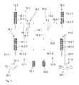
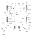
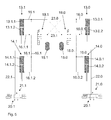
- each shut-off 19.0, 19.1 and switching valves 20.0, 20.1 are so interconnected by non-illustrated circuitry means that when shut-off the shut-off valve 19.0, 19.1 the associated switching valve 20.0, 20.1 is switched to flow position, as the Fig. 3 shows, and at flow position of the shut-off valve 19.0, 19.1, the associated switching valve 20.0, 20.1 in the shut-off position, such as Figure 4 shows, is switched.
- a switching pulse which is generated by hand or via an on-board computer to the shut-off valves 19.0, 19.1, the switching of these valves between in the Fig. 3 and 4 reached switching positions shown.
- the circuitry connection of the shut-off valves 19.0, 19.1 with the switching valves 20.0, 20.1 these are also according to the in the Fig. 3 and 4 Switched positions shown switched to the corresponding switching position.
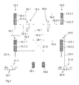
- the compensation and suspension plan for the compensating and / or suspension cylinders 13.0, 13.1, 14.0, 14.1 of the tandem axle 9 according to Fig. 5 and 6 differs from the compensation and suspension plan for the compensating and / or suspension cylinders 13.0, 13.1, 14.0, 14.1 of the tandem axle 9 according to Fig. 3 and 4 merely by a cross-connection of the displacements 13.0.1, 13.1.1, 13.0.2, 13.1.2 of the two rear axle 12 of the tandem axle 9 associated cylinder 13.0 and 13.1.
- a better roll stability is achieved.
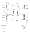
- the compensation and suspension plan for the compensating and / or suspension cylinders 13.0, 13.1, 14.0, 14.1 of the tandem axle 9 according to Fig. 7 and 8th differs from the compensation and suspension plan for the compensating and / or suspension cylinders 13.0, 13.1, 14.0, 14.1 of the tandem axle 9 according to Fig. 3 and 4 only by a cross-connection of the displacements 14.0.1, 14.1.1, 14.0.2, 14.1.2 of the two of the front axle 11 of the tandem axle 9 associated cylinder 14.0 and 14.1.
- a better roll stability is achieved.
- the compensation and suspension plan for the compensating and / or suspension cylinders 13.0, 13.1, 14.0, 14.1 of the tandem axle 9 according to Fig. 9 and 10 differs from the compensation and suspension plan for the compensating and / or suspension cylinders 13.0, 13.1, 14.0, 14.1 of the tandem axle 9 according to Fig. 3 and 4 first by a first cross-connection of the displacements 13.0.1, 13.1.1, 13.0.2, 13.1.2 of the two rear axle 12 of the tandem axle 9 associated cylinder 13.0 and 13.1.
- the compensation and suspension plan for the compensating and / or suspension cylinders 13.0, 13.1, 14.0, 14.1 of the tandem axle 9 according to Fig. 9 and 10 differs further from the compensation and suspension plan for the compensating and / or suspension cylinders 13.0, 13.1, 14.0, 14.1 of the tandem axle 9 according to Fig. 3 and 4 additionally by a second cross-connection of the displacements 14.0.1, 14.1.1, 14.0.2, 14.1.2 of the two of the front axle 11 of the tandem axle 9 associated cylinder 14.0 and 14.1.
Landscapes
- Engineering & Computer Science (AREA)
- Mechanical Engineering (AREA)
- Vehicle Body Suspensions (AREA)
Abstract
Description
Die Erfindung betrifft ein Anhängefahrzeug mit Tandemachse gemäß des Oberbegriffes des Patentanspruches 1.The invention relates to a trailer vehicle with tandem axle according to the preamble of
Ein derartiges Anhängefahrzeug mit Tandemachse ist in der Praxis bekannt geworden. Derartige mit Tandemachsen ausgestattete Anhängefahrzeuge weisen Federungs- und/oder Ausgleichssysteme auf. Hierdurch ist es möglich, dass die vordere Achse bei Fahrwerken mit Tandemachsen komplett entlastet wird oder auch ganz angehoben werden kann.Such a trailer vehicle with tandem axle has become known in practice. Such equipped with tandem axles trailer vehicles have suspension and / or compensation systems. This makes it possible that the front axle is completely relieved in chassis with tandem axles or can be lifted completely.
Grundsätzlich ist es bereits beispielsweise durch
Der Erfindung liegt die Aufgabe zu Grunde, in einfacher Weise bei einem hydraulischen Ausgleichssystem für die Tandemachse eines Anhängefahrzeuges durch Vergrößerung der Stützlast auf das ziehende Fahrzeug die Traktion des ziehenden Fahrzeuges verstärken zu können.The invention is based on the object to be able to reinforce the traction of the towing vehicle in a simple manner in a hydraulic compensation system for the tandem axle of a trailer by increasing the vertical load on the towing vehicle.
Diese Aufgabe wird erfindungsgemäß dadurch gelöst, dass in den zu den kolbenstangenseitigen zylinderringförmigen Hubräumen der der hinteren Achse der Tandemachse zugeordneten Ausgleichs- und/oder Federungszylinder führenden Verbindungsleitungen jeweils ein Absperrventil angeordnet sind, dass von der zwischen dem jeweiligen kolbenstangenseitigen zylinderringförmigen Hubraum der hinteren Ausgleichs- und/oder Federungszylinder und dem zugeordneten Absperrventil sich befindlichen Verbindungsleitung jeweils eine zu einem Hydrauliksystem führende und mit einem Umschaltventil versehene Zweigleitung abzweigt.This object is achieved in that in the piston rod-side cylinder-cylindrical displacements of the rear axle of the tandem axle associated compensating and / or suspension cylinder leading connecting lines are each a shut-off valve arranged that of the between the respective piston rod side cylindrical displacement of the rear compensation and / or suspension cylinder and the associated shut-off valve located branch line branches off each leading to a hydraulic system and provided with a switching valve branch line.
Infolge dieser Maßnahmen lässt sich in einfacher Weise die Lastverteilung des Federungs- und/oder Ausgleichssystems des Tandemfahrwerks in einfacher Weise so verändern, dass mehr Gewicht von dem Anhängerfahrzeug auf das ziehende Fahrzeug, beispielsweise einem Ackerschlepper übertragen wird. Beim Federungssystem bleiben die federnden Eigenschaften des Fahrwerks enthalten. Erfindungsgemäß wird durch die vorgeschlagenen Maßnahmen die vordere Achse der Tandemachse entlastet. Bei entsprechender Auslegung des Systems bleibt eine Restlast auch noch auf der vorderen Achse der Tandemachse erhalten. Dies wirkt sich insbesondere, wenn die Hinterachse der Tandemachse als gelenkte Achse ausgebildet ist, für die Spurhaltung des Fahrzeugs vorteilhaft aus.As a result of these measures, the load distribution of the suspension and / or balancing system of the tandem running gear can be changed in a simple manner so that more weight is transferred from the trailer to the towing vehicle, such as an agricultural tractor. The suspension system retains the resilient properties of the chassis. According to the invention, the front axle of the tandem axle is relieved by the proposed measures. With appropriate design of the system, a residual load remains even on the front axle of the tandem axle. This has an effect, in particular, when the rear axle of the tandem axle is designed as a steered axle, advantageous for tracking the vehicle.
Bei der Tandemachse, die ein Ausgleichs- und/oder Federungssystem aufweist, wirkt auf der Kolbenbodenseite wie auch auf der Kolbenstangenseite im normalen Federungsmodus der gleiche Hydraulikdruck. Hierdurch wird erreicht, dass die Last, die vom Anhängerfahrzeug auf die Federungszylinders wirkt, effektiv nur von der Fläche der Kolbenstange getragen wird. Zur Erhöhung der Traktion wird der kolbenstangenseitige zylinderförmige Hubraum durch die Sperrstellung des Absperrventil von dem übrigen System abgetrennt und drucklos geschaltet, so dass nur die Kolbenbodenseite, also die komplette Kolbenfläche des der hinteren Achse zugeordneten Ausgleichs- und/oder Federungszylinder die Last trägt. Hierdurch wird die vordere Achse der Tandemachse entlastet. Dies führt zu einer höheren Last bzw. Gewichtsübertragung vom Anhängerfahrzeug auf das ziehende Fahrzeug, beispielsweise den Ackerschlepper. Hierdurch ergibt sich eine gewollte Traktionsverstärkung für den Ackerschlepper.In the tandem axle, which has a compensation and / or suspension system acts on the piston bottom side as well as on the piston rod side in the normal suspension mode, the same hydraulic pressure. This ensures that the load acting on the suspension cylinder of the trailer vehicle is effectively only supported by the surface of the piston rod. To increase the traction of the piston rod-side cylindrical displacement is separated by the blocking position of the shut-off valve from the rest of the system and depressurized, so that only the piston bottom side, so the complete piston surface of the rear axle associated compensating and / or suspension cylinder carries the load. As a result, the front axle of the tandem axle is relieved. This leads to a higher load or weight transfer from the trailer to the towing vehicle, such as the tractor. This results in a desired traction gain for the tractor.
Um in einfacher Weise die im kolbenstangenseitigen Hubraum des der hinteren Achse der Tandemachse zugeordneten Federungszylinders zur größeren Lastübertragung oder Gewichtsübertragung von dem angehängten Fahrzeug auf das ziehende Fahrzeug drucklos zu schalten, ist vorgesehen, dass die einer Verbindungsleitung jeweils zugeordneten Absperrventile und Umschaltventile durch schaltungstechnische Mittel so mit miteinander verknüpft sind, dass bei Absperrstellung des Absperrventiles das zugeordnete Umschaltventil in Durchflussstellung geschaltet ist und bei Durchflussstellung des Absperrventiles das zugeordnete Umschaltventil in Absperrstellung geschaltet ist.To depressurize in a simple manner in the piston rod-side displacement of the rear axle of the tandem axle associated suspension cylinder for greater load transfer or weight transfer from the attached vehicle to the towing vehicle, it is provided that a connecting line respectively associated shut-off valves and switching valves by circuit engineering means so linked to each other, that in shut-off position of the shut-off valve, the associated change-over valve is switched to the flow position and the associated switching valve is switched to the shut-off position when the shut-off valve is flowed through.
In einfacher Weise ist das das Absperrventil als 2/2 - Wegeventil ausgebildet.In a simple way, the shut-off valve is designed as a 2/2 - way valve.
Um ein gutes Federungssystem für die Ausgleichs- und/oder Federungszylinder in einfacher Weise zu schaffen, ist vorgesehen, dass in zumindest einigen der Verbindungsleitungen ein hydropneumatisches Federungselement angeordnet ist.In order to provide a good suspension system for the compensating and / or suspension cylinders in a simple manner, it is provided that a hydropneumatic suspension element is arranged in at least some of the connecting lines.
Weitere Einzelheiten der Erfindung sind der Beispielsbeschreibung zu entnehmen. Die Zeichnungen zeigen
- Fig.1
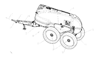
- eine als landwirtschaftliche Feldspritze ausgebildetes gezogenes Anhängerfahrzeug mit Tandemachse ohne Spritzgestänge in Prinzipdarstellung und in perspektivischer Ansicht,
- Fig.2
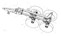
- den Tragrahmen mit der Tandemachse in Prinzipdarstellung und in perspektivischer Ansicht,
- Fig.3
- den Ausgleichs- und Federungsplan für die Ausgleichs- und/oder Federungszylinder der Tandemachse des gezogenen Anhängerfahrzeuges in Prinzipdarstellung in der Schaltposition, in welcher die beiden Achsen der Tandemachse in gleicher Weise belastet werden,
- Fig.4
- den Ausgleichs- und Federungsplan nach
Fig.3 für die Ausgleichs- und/oder Federungszylinder der Tandemachse des gezogenen Anhängerfahrzeuges in Prinzipdarstellung in der Schaltposition, in welcher die Vorderachse der Tandemachse entlastet wird, - Fig.5
- ein weiterer Ausgleichs- und Federungsplan für die Ausgleichs- und/oder Federungszylinder der Tandemachse des gezogenen Anhängerfahrzeuges in Prinzipdarstellung in der Schaltposition, in welcher die beiden Achsen der Tandemachse in gleicher Weise belastet werden,
- Fig.6
- den Ausgleichs- und Federungsplan nach
Fig.5 für die Ausgleichs- und/oder Federungszylinder der Tandemachse des gezogenen Anhängerfahrzeuges in Prinzipdarstellung in der Schaltposition, in welcher die Vorderachse der Tandemachse entlastet wird, - Fig.7
- ein weiterer Ausgleichs- und Federungsplan für die Ausgleichs- und/oder Federungszylinder der Tandemachse des gezogenen Anhängerfahrzeuges in Prinzipdarstellung in der Schaltposition, in welcher die beiden Achsen der Tandemachse in gleicher Weise belastet werden,
- Fig.8
- den Ausgleichs- und Federungsplan nach
Fig.7 für die Ausgleichs- und/oder Federungszylinder der Tandemachse des gezogenen Anhängerfahrzeuges in Prinzipdarstellung in der Schaltposition, in welcher die Vorderachse der Tandemachse entlastet wird, - Fig.9
- ein weiterer Ausgleichs- und Federungsplan für die Ausgleichs- und/oder Federungszylinder der Tandemachse des gezogenen Anhängerfahrzeuges in Prinzipdarstellung in der Schaltposition, in welcher die beiden Achsen der Tandemachse in gleicher Weise belastet werden und
- Fig.10
- den Ausgleichs- und Federungsplan nach
Fig.9 für die Ausgleichs- und/oder Federungszylinder der Tandemachse des gezogenen Anhängerfahrzeuges in Prinzipdarstellung in der Schaltposition, in welcher die Vorderachse der Tandemachse entlastet wird.
- Fig.1
- Trained as an agricultural field sprayer towed trailer vehicle with tandem axle without spray boom in a schematic representation and in perspective view,
- Fig.2
- the support frame with the tandem axle in schematic representation and in perspective view,
- Figure 3
- the compensation and suspension plan for the compensating and / or suspension cylinders of the tandem axle of the towed vehicle drawn in schematic representation in the switching position in which the two axes of the tandem axle are loaded in the same way,
- Figure 4
- the compensation and suspension plan
Figure 3 for the compensating and / or suspension cylinders of the tandem axle of the towed trailer vehicle in schematic representation in the shift position, in which the front axle of the tandem axle is relieved, - Figure 5
- a further compensation and suspension plan for the compensating and / or suspension cylinders of the tandem axle of the towed trailer vehicle in schematic representation in the shift position, in which the two axles of the tandem axle are loaded in the same way,
- Figure 6
- the compensation and suspension plan
Figure 5 for the balancing and / or suspension cylinders of the tandem axle of the towed Trailer vehicle in schematic representation in the shift position in which the front axle of the tandem axle is relieved, - Figure 7
- a further compensation and suspension plan for the compensating and / or suspension cylinders of the tandem axle of the towed trailer vehicle in schematic representation in the shift position, in which the two axles of the tandem axle are loaded in the same way,
- Figure 8
- the compensation and suspension plan
Figure 7 for the compensating and / or suspension cylinders of the tandem axle of the towed trailer vehicle in schematic representation in the shift position, in which the front axle of the tandem axle is relieved, - Figure 9
- a further compensation and suspension plan for the compensation and / or suspension cylinder of the tandem axle of the towed trailer vehicle in a schematic representation in the shift position, in which the two axes of the tandem axle are loaded in the same way and
- Figure 10
- the compensation and suspension plan
Figure 9 for the compensating and / or suspension cylinders of the tandem axle of the towed trailer vehicle in schematic representation in the shift position, in which the front axle of the tandem axle is relieved.
Die als gezogene landwirtschaftliche Pflanzenschutzspritze 1 ausgebildete Verteilmaschine bildet ein Anhängefahrzeug, welches an die Kuppeleinrichtung 2 eines die Maschine ziehenden Fahrzeuges, beispielsweise eines Ackerschleppers anzukuppeln ist. Die Pflanzenschutzspritze 1 weist einen Tragrahmen 3 auf, an dessen Vorderseite eine Zugdeichsel 4 mit einer Zug- und Kuppelvorrichtung 5 angeordnet ist. Auf dem Rahmen 3 ist ein Vorratsbehälter 6 zur Aufnahme des auszubringenden Materials, hier Pflanzenschutzmittel, angeordnet. An der Rückseite 7 sind an dem Rahmen 3 in nicht dargestellter Weise Verteilelemente, beispielsweise ein Verteilergestänge, welches sich quer zur Fahrtrichtung 8 erstreckt, angeordnet.Trained as drawn agricultural
Der Tragrahmen 3 stützt sich im hinteren Bereich auf den an einer Tandemachse 9 angeordneten Laufrädern 10 auf dem Boden ab. Die Tandemachse 9 weist eine vordere Achse 1 und eine hintere Achse 12 auf, welche über Verbindungselemente mit den Tragrahmen 3 verbunden sind. Des Weiteren ist jeder Tandemachse 11, 12 im Bereich des jeweiligen Laufrades 10 der Tandemachse 9 zwischen der jeweiligen Achse 11 und dem Tragrahmen 3 ein Ausgleichs- und/oder Federungszylinders 13.0, 13.1, 14.0, 14.1 angeordnet. Diese Ausgleichs- und/oder Federungszylinder 13.0, 13.1, 14.0, 14.1 sind Bestandteil einer hydropneumatischen Ausgleichs- und/oder Federungseinrichtung.The
Die Zylinder 13.0, 13.1, 14.0, 14.1 weisen jeweils einen kolbenbodenseitigen Hubraum 13.0.1, 13.1.1, 14.0.1, 14.1, 1 und einen kolbenstangenseitigen zylinderringförmigen Hubraum 13.0.2, 13.1.2, 14.0.2, 14.1.2 auf.The cylinders 13.0, 13.1, 14.0, 14.1 each have a piston-bottom side displacement 13.0.1, 13.1.1, 14.0.1, 14.1, 1 and a piston rod-side cylinder-shaped displacement 13.0.2, 13.1.2, 14.0.2, 14.1.2 ,
Bei dem Ausgleichs- und Federungsplan für die Ausgleichs- und/oder Federungszylinder 13.0, 13.1, 14.0, 14.1 der Tandemachse 9 gemäß
In den zu den kolbenstangenseitigen zylinderringförmigen Hubräumen der hinteren Tandemachse 12 zugeordneten Zylindern 13.0 und 13.1 führenden Verbindungsleitungen 16.0.1 und 16.1.1 ist jeweils ein Absperrventil 19.0, 10.1, welches beispielsweise bei 2/2 - Wegeventil ausgebildet sein kann, angeordnet. Weiterhin ist in der zwischen dem jeweiligen kolbenstangenseitigen zylinderringförmigen Hubraum 13.0.2, 13.1.2 des der hinteren Achse 12 zugeordneten Zylinders 13.0, 13.1 und dem zugeordneten Absperrventil 19.0, 19.1 sich befindenden Verbindungsleitung 16.0, 16.1 eine zu einem Hydrauliksystem 20.0, 20.1 führende und mit einem Umschaltventil 21.0, 21.1 versehene Zweigleitung 22.0, 22.1 in abzweigender Weise verbunden.In the cylinders 13.0 and 13.1 associated with the piston rod-side cylinder-shaped displacements of the rear tandem axle 12 connecting lines 16.0.1 and 16.1.1 is in each case a check valve 19.0, 10.1, which may be formed, for example, 2/2 - way valve arranged. Furthermore, in between the respective piston rod side cylinder-shaped displacement 13.0.2, 13.1.2 of the rear axle 12 associated cylinder 13.0, 13.1 and the associated shut-off valve 19.0, 19.1 located connecting line 16.0, 16.1 leading to a hydraulic system 20.0, 20.1 and with a branching valve 21.0, 21.1 provided branch 22.0, 22.1 connected in a branching manner.
Die jeweils in einem Ausgleichssystem 17.0, 17.1 jeweils einander zugeordneten Absperr- 19.0, 19.1 und Umschaltventile 20.0, 20.1 sind durch nicht dargestellte schaltungstechnische Mittel so miteinander verknüpft, dass bei Absperrstellung des Absperrventils 19.0, 19.1 das zugeordnete Umschaltventil 20.0, 20.1 in Durchflussstellung geschaltet ist, wie die
Wenn das jeweilige Absperrventil 19.0, 19.1, welches dem kolbenstangenseitigen Hubraum 13.0.2, 13.1.2 des jeweiligen hinteren Zylinders 13.0. 13.1 zugeordnet ist, in Absperrstellung gemäß
In der Schaltstellung des jeweiligen Absperrventils 19.0, 19.1 und des jeweiligen Umschaltventils 20.0, 20.1 gemäß
In der Schaltstellung des jeweiligen Absperrventils 19.0, 19.1 und des jeweiligen Umschaltventils 20.0, 20.1 gemäß
Der Ausgleichs- und Federungsplan für die Ausgleichs- und/oder Federungszylinder 13.0, 13.1, 14.0, 14.1 der Tandemachse 9 gemäß
Die Umschaltung des Systems zwischen Normalmodus gemäß
Der Ausgleichs- und Federungsplan für die Ausgleichs- und/oder Federungszylinder 13.0, 13.1, 14.0, 14.1 der Tandemachse 9 gemäß
Die Umschaltung des Systems zwischen Normalmodus gemäß
Der Ausgleichs- und Federungsplan für die Ausgleichs- und/oder Federungszylinder 13.0, 13.1, 14.0, 14.1 der Tandemachse 9 gemäß
Der Ausgleichs- und Federungsplan für die Ausgleichs- und/oder Federungszylinder 13.0, 13.1, 14.0, 14.1 der Tandemachse 9 gemäß
Die Umschaltung des Systems zwischen Normalmodus gemäß
Claims (4)
Priority Applications (1)
| Application Number | Priority Date | Filing Date | Title |
|---|---|---|---|
| PL14401026T PL2772371T3 (en) | 2013-02-27 | 2014-02-19 | Trailer vehicle with a tandem axle |
Applications Claiming Priority (1)
| Application Number | Priority Date | Filing Date | Title |
|---|---|---|---|
| DE201310101924 DE102013101924A1 (en) | 2013-02-27 | 2013-02-27 | Trailer with tandem axle |
Publications (2)
| Publication Number | Publication Date |
|---|---|
| EP2772371A1 true EP2772371A1 (en) | 2014-09-03 |
| EP2772371B1 EP2772371B1 (en) | 2017-02-01 |
Family
ID=50289611
Family Applications (1)
| Application Number | Title | Priority Date | Filing Date |
|---|---|---|---|
| EP14401026.1A Active EP2772371B1 (en) | 2013-02-27 | 2014-02-19 | Trailer vehicle with a tandem axle |
Country Status (4)
| Country | Link |
|---|---|
| EP (1) | EP2772371B1 (en) |
| DE (1) | DE102013101924A1 (en) |
| DK (1) | DK2772371T3 (en) |
| PL (1) | PL2772371T3 (en) |
Cited By (4)
| Publication number | Priority date | Publication date | Assignee | Title |
|---|---|---|---|---|
| CN104691270A (en) * | 2015-01-20 | 2015-06-10 | 徐州重型机械有限公司 | Axle balance control system of self-walking type aerial working vehicle |
| CN106004319A (en) * | 2016-07-13 | 2016-10-12 | 徐州重型机械有限公司 | Oil gas suspension system with balanced vehicle load |
| DE102016119883A1 (en) * | 2016-10-19 | 2018-04-19 | Amazonen-Werke H. Dreyer Gmbh & Co. Kg | Agricultural machine |
| EP3366501A1 (en) * | 2017-02-22 | 2018-08-29 | HORSCH LEEB Application Systems GmbH | Landing gear of an agricultural vehicle and method for its suspension and/or damping control |
Citations (8)
| Publication number | Priority date | Publication date | Assignee | Title |
|---|---|---|---|---|
| US3334913A (en) * | 1965-05-19 | 1967-08-08 | Charles E Margala | Flexible suspension for load-bearing road vehicles |
| US3970327A (en) * | 1975-06-04 | 1976-07-20 | Caterpillar Tractor Co. | Suspension and load leveling for an urban hauler |
| US4222578A (en) * | 1978-03-06 | 1980-09-16 | Caterpillar Tractor Co. | Tandem wheel proportioning arrangement |
| DE4402182C2 (en) | 1994-01-26 | 1997-04-10 | Zunhammer Sebastian Dipl Ing F | Vehicle trailer |
| EP1571015A2 (en) | 2004-03-04 | 2005-09-07 | WABCO GmbH & CO. OHG | Start-assist control method |
| US20060192361A1 (en) * | 2005-02-28 | 2006-08-31 | Oshkosh Truck Corporation | Suspension system |
| DE102009035525A1 (en) * | 2009-07-31 | 2011-03-03 | Wabco Gmbh | Method for increasing traction in commercial drawing vehicle, involves lying semi-trailer in direction of front lift axle and rear axle |
| EP2377700A1 (en) * | 2010-04-15 | 2011-10-19 | Industrie Cometto S.p.A. | Method for forming a modular convoy for outsize loads, modular convoy and trailer for such a convoy |
-
2013
- 2013-02-27 DE DE201310101924 patent/DE102013101924A1/en not_active Withdrawn
-
2014
- 2014-02-19 PL PL14401026T patent/PL2772371T3/en unknown
- 2014-02-19 DK DK14401026.1T patent/DK2772371T3/en active
- 2014-02-19 EP EP14401026.1A patent/EP2772371B1/en active Active
Patent Citations (8)
| Publication number | Priority date | Publication date | Assignee | Title |
|---|---|---|---|---|
| US3334913A (en) * | 1965-05-19 | 1967-08-08 | Charles E Margala | Flexible suspension for load-bearing road vehicles |
| US3970327A (en) * | 1975-06-04 | 1976-07-20 | Caterpillar Tractor Co. | Suspension and load leveling for an urban hauler |
| US4222578A (en) * | 1978-03-06 | 1980-09-16 | Caterpillar Tractor Co. | Tandem wheel proportioning arrangement |
| DE4402182C2 (en) | 1994-01-26 | 1997-04-10 | Zunhammer Sebastian Dipl Ing F | Vehicle trailer |
| EP1571015A2 (en) | 2004-03-04 | 2005-09-07 | WABCO GmbH & CO. OHG | Start-assist control method |
| US20060192361A1 (en) * | 2005-02-28 | 2006-08-31 | Oshkosh Truck Corporation | Suspension system |
| DE102009035525A1 (en) * | 2009-07-31 | 2011-03-03 | Wabco Gmbh | Method for increasing traction in commercial drawing vehicle, involves lying semi-trailer in direction of front lift axle and rear axle |
| EP2377700A1 (en) * | 2010-04-15 | 2011-10-19 | Industrie Cometto S.p.A. | Method for forming a modular convoy for outsize loads, modular convoy and trailer for such a convoy |
Cited By (5)
| Publication number | Priority date | Publication date | Assignee | Title |
|---|---|---|---|---|
| CN104691270A (en) * | 2015-01-20 | 2015-06-10 | 徐州重型机械有限公司 | Axle balance control system of self-walking type aerial working vehicle |
| CN106004319A (en) * | 2016-07-13 | 2016-10-12 | 徐州重型机械有限公司 | Oil gas suspension system with balanced vehicle load |
| CN106004319B (en) * | 2016-07-13 | 2018-10-30 | 徐州重型机械有限公司 | A kind of hydro-pneumatic suspension system with balancing vehicle axle load |
| DE102016119883A1 (en) * | 2016-10-19 | 2018-04-19 | Amazonen-Werke H. Dreyer Gmbh & Co. Kg | Agricultural machine |
| EP3366501A1 (en) * | 2017-02-22 | 2018-08-29 | HORSCH LEEB Application Systems GmbH | Landing gear of an agricultural vehicle and method for its suspension and/or damping control |
Also Published As
| Publication number | Publication date |
|---|---|
| PL2772371T3 (en) | 2017-07-31 |
| EP2772371B1 (en) | 2017-02-01 |
| DE102013101924A1 (en) | 2014-09-11 |
| DK2772371T3 (en) | 2017-05-15 |
Similar Documents
| Publication | Publication Date | Title |
|---|---|---|
| DE1580793A1 (en) | Device for hydraulic wheel pressure compensation for four- or multi-wheel vehicles | |
| EP2772371B1 (en) | Trailer vehicle with a tandem axle | |
| DE102014110551A1 (en) | Agricultural vehicle | |
| DE102011050578A1 (en) | Agricultural distributor with distributor rods | |
| EP1816059B1 (en) | Super-heavy lorry coupled to a tractor through a gooseneck | |
| EP2227412B1 (en) | Hydraulic steering system for vehicle trailers | |
| DE202012102356U1 (en) | Trailer vehicle with articulated drawbar | |
| EP2685109B1 (en) | Control assembly for a hydropneumatic suspension system and hydropneumatic suspension system having such a control assembly | |
| EP1614335B1 (en) | Driving support | |
| DE498399C (en) | Connection between towing vehicle and trailer | |
| EP2239188B1 (en) | Goose-neck for a vehicle, especially for a heavy duty vehicle | |
| DE2407970A1 (en) | AGRICULTURAL TRACTOR | |
| DE102020112927A1 (en) | PULLED AGRICULTURAL MACHINE AND METHOD OF CONTROLLING A STRUCTURAL FORCE OF A PULLED AGRICULTURAL MACHINE | |
| DE10240236A1 (en) | Supporting wheel arrangement for vehicle, e.g. harvesting machine, is accommodated by frame(s) that interacts with functional assemblies and axle(s); wheel is arranged between at least 2 vehicle axles | |
| EP2425695B1 (en) | Soil cultivation device with hydraulics for increasing traction force | |
| DE102011050579A1 (en) | Agricultural distributor with distributor rods | |
| EP3025570B1 (en) | Pulled agricultural machine | |
| DE2319611B1 (en) | Pipe rupture protection for hydraulic chassis supports of heavy-duty vehicles or the like | |
| DE102015115641A1 (en) | Agricultural vehicle | |
| DE102022121383A1 (en) | Transport trailer | |
| DE102015115696A1 (en) | Towing device for an agricultural machine arrangement | |
| DE102013021339A1 (en) | independent suspension | |
| DE102019135685A1 (en) | Trailers, in particular forestry trailers | |
| DE102012104946A1 (en) | Chassis frame for agricultural vehicle, particularly field sprayer, has guide rod of wheel suspension, which is connected with steering knuckle upper part in immovable manner and with steering knuckle bottom part in movable manner | |
| DE102012104945A1 (en) | Chassis for agricultural vehicle i.e. self-propelled field sprayer, has upright running aligned guide bars displaceably arranged in guide bearings i.e. hydraulic cylinders, in relation to frame in upright direction |
Legal Events
| Date | Code | Title | Description |
|---|---|---|---|
| PUAI | Public reference made under article 153(3) epc to a published international application that has entered the european phase |
Free format text: ORIGINAL CODE: 0009012 |
|
| 17P | Request for examination filed |
Effective date: 20140219 |
|
| AK | Designated contracting states |
Kind code of ref document: A1 Designated state(s): AL AT BE BG CH CY CZ DE DK EE ES FI FR GB GR HR HU IE IS IT LI LT LU LV MC MK MT NL NO PL PT RO RS SE SI SK SM TR |
|
| AX | Request for extension of the european patent |
Extension state: BA ME |
|
| R17P | Request for examination filed (corrected) |
Effective date: 20150216 |
|
| RBV | Designated contracting states (corrected) |
Designated state(s): AL AT BE BG CH CY CZ DE DK EE ES FI FR GB GR HR HU IE IS IT LI LT LU LV MC MK MT NL NO PL PT RO RS SE SI SK SM TR |
|
| GRAP | Despatch of communication of intention to grant a patent |
Free format text: ORIGINAL CODE: EPIDOSNIGR1 |
|
| INTG | Intention to grant announced |
Effective date: 20161115 |
|
| GRAS | Grant fee paid |
Free format text: ORIGINAL CODE: EPIDOSNIGR3 |
|
| GRAA | (expected) grant |
Free format text: ORIGINAL CODE: 0009210 |
|
| AK | Designated contracting states |
Kind code of ref document: B1 Designated state(s): AL AT BE BG CH CY CZ DE DK EE ES FI FR GB GR HR HU IE IS IT LI LT LU LV MC MK MT NL NO PL PT RO RS SE SI SK SM TR |
|
| REG | Reference to a national code |
Ref country code: GB Ref legal event code: FG4D Free format text: NOT ENGLISH |
|
| REG | Reference to a national code |
Ref country code: CH Ref legal event code: EP Ref country code: AT Ref legal event code: REF Ref document number: 865233 Country of ref document: AT Kind code of ref document: T Effective date: 20170215 |
|
| REG | Reference to a national code |
Ref country code: IE Ref legal event code: FG4D Free format text: LANGUAGE OF EP DOCUMENT: GERMAN |
|
| REG | Reference to a national code |
Ref country code: FR Ref legal event code: PLFP Year of fee payment: 4 |
|
| REG | Reference to a national code |
Ref country code: DE Ref legal event code: R096 Ref document number: 502014002608 Country of ref document: DE |
|
| REG | Reference to a national code |
Ref country code: NL Ref legal event code: FP |
|
| REG | Reference to a national code |
Ref country code: DK Ref legal event code: T3 Effective date: 20170509 |
|
| REG | Reference to a national code |
Ref country code: LT Ref legal event code: MG4D |
|
| PG25 | Lapsed in a contracting state [announced via postgrant information from national office to epo] |
Ref country code: LT Free format text: LAPSE BECAUSE OF FAILURE TO SUBMIT A TRANSLATION OF THE DESCRIPTION OR TO PAY THE FEE WITHIN THE PRESCRIBED TIME-LIMIT Effective date: 20170201 Ref country code: GR Free format text: LAPSE BECAUSE OF FAILURE TO SUBMIT A TRANSLATION OF THE DESCRIPTION OR TO PAY THE FEE WITHIN THE PRESCRIBED TIME-LIMIT Effective date: 20170502 Ref country code: IS Free format text: LAPSE BECAUSE OF FAILURE TO SUBMIT A TRANSLATION OF THE DESCRIPTION OR TO PAY THE FEE WITHIN THE PRESCRIBED TIME-LIMIT Effective date: 20170601 Ref country code: HR Free format text: LAPSE BECAUSE OF FAILURE TO SUBMIT A TRANSLATION OF THE DESCRIPTION OR TO PAY THE FEE WITHIN THE PRESCRIBED TIME-LIMIT Effective date: 20170201 Ref country code: NO Free format text: LAPSE BECAUSE OF FAILURE TO SUBMIT A TRANSLATION OF THE DESCRIPTION OR TO PAY THE FEE WITHIN THE PRESCRIBED TIME-LIMIT Effective date: 20170501 Ref country code: FI Free format text: LAPSE BECAUSE OF FAILURE TO SUBMIT A TRANSLATION OF THE DESCRIPTION OR TO PAY THE FEE WITHIN THE PRESCRIBED TIME-LIMIT Effective date: 20170201 |
|
| PG25 | Lapsed in a contracting state [announced via postgrant information from national office to epo] |
Ref country code: BG Free format text: LAPSE BECAUSE OF FAILURE TO SUBMIT A TRANSLATION OF THE DESCRIPTION OR TO PAY THE FEE WITHIN THE PRESCRIBED TIME-LIMIT Effective date: 20170501 Ref country code: SE Free format text: LAPSE BECAUSE OF FAILURE TO SUBMIT A TRANSLATION OF THE DESCRIPTION OR TO PAY THE FEE WITHIN THE PRESCRIBED TIME-LIMIT Effective date: 20170201 Ref country code: RS Free format text: LAPSE BECAUSE OF FAILURE TO SUBMIT A TRANSLATION OF THE DESCRIPTION OR TO PAY THE FEE WITHIN THE PRESCRIBED TIME-LIMIT Effective date: 20170201 Ref country code: PT Free format text: LAPSE BECAUSE OF FAILURE TO SUBMIT A TRANSLATION OF THE DESCRIPTION OR TO PAY THE FEE WITHIN THE PRESCRIBED TIME-LIMIT Effective date: 20170601 Ref country code: ES Free format text: LAPSE BECAUSE OF FAILURE TO SUBMIT A TRANSLATION OF THE DESCRIPTION OR TO PAY THE FEE WITHIN THE PRESCRIBED TIME-LIMIT Effective date: 20170201 Ref country code: LV Free format text: LAPSE BECAUSE OF FAILURE TO SUBMIT A TRANSLATION OF THE DESCRIPTION OR TO PAY THE FEE WITHIN THE PRESCRIBED TIME-LIMIT Effective date: 20170201 |
|
| REG | Reference to a national code |
Ref country code: CH Ref legal event code: PL |
|
| PG25 | Lapsed in a contracting state [announced via postgrant information from national office to epo] |
Ref country code: IT Free format text: LAPSE BECAUSE OF FAILURE TO SUBMIT A TRANSLATION OF THE DESCRIPTION OR TO PAY THE FEE WITHIN THE PRESCRIBED TIME-LIMIT Effective date: 20170201 Ref country code: LI Free format text: LAPSE BECAUSE OF NON-PAYMENT OF DUE FEES Effective date: 20170228 Ref country code: RO Free format text: LAPSE BECAUSE OF FAILURE TO SUBMIT A TRANSLATION OF THE DESCRIPTION OR TO PAY THE FEE WITHIN THE PRESCRIBED TIME-LIMIT Effective date: 20170201 Ref country code: CH Free format text: LAPSE BECAUSE OF NON-PAYMENT OF DUE FEES Effective date: 20170228 Ref country code: SK Free format text: LAPSE BECAUSE OF FAILURE TO SUBMIT A TRANSLATION OF THE DESCRIPTION OR TO PAY THE FEE WITHIN THE PRESCRIBED TIME-LIMIT Effective date: 20170201 Ref country code: EE Free format text: LAPSE BECAUSE OF FAILURE TO SUBMIT A TRANSLATION OF THE DESCRIPTION OR TO PAY THE FEE WITHIN THE PRESCRIBED TIME-LIMIT Effective date: 20170201 |
|
| REG | Reference to a national code |
Ref country code: DE Ref legal event code: R097 Ref document number: 502014002608 Country of ref document: DE |
|
| REG | Reference to a national code |
Ref country code: IE Ref legal event code: MM4A |
|
| PG25 | Lapsed in a contracting state [announced via postgrant information from national office to epo] |
Ref country code: MC Free format text: LAPSE BECAUSE OF FAILURE TO SUBMIT A TRANSLATION OF THE DESCRIPTION OR TO PAY THE FEE WITHIN THE PRESCRIBED TIME-LIMIT Effective date: 20170201 Ref country code: SM Free format text: LAPSE BECAUSE OF FAILURE TO SUBMIT A TRANSLATION OF THE DESCRIPTION OR TO PAY THE FEE WITHIN THE PRESCRIBED TIME-LIMIT Effective date: 20170201 |
|
| PLBE | No opposition filed within time limit |
Free format text: ORIGINAL CODE: 0009261 |
|
| STAA | Information on the status of an ep patent application or granted ep patent |
Free format text: STATUS: NO OPPOSITION FILED WITHIN TIME LIMIT |
|
| PG25 | Lapsed in a contracting state [announced via postgrant information from national office to epo] |
Ref country code: LU Free format text: LAPSE BECAUSE OF NON-PAYMENT OF DUE FEES Effective date: 20170219 |
|
| 26N | No opposition filed |
Effective date: 20171103 |
|
| REG | Reference to a national code |
Ref country code: FR Ref legal event code: PLFP Year of fee payment: 5 |
|
| REG | Reference to a national code |
Ref country code: BE Ref legal event code: MM Effective date: 20170228 |
|
| PG25 | Lapsed in a contracting state [announced via postgrant information from national office to epo] |
Ref country code: IE Free format text: LAPSE BECAUSE OF NON-PAYMENT OF DUE FEES Effective date: 20170219 Ref country code: SI Free format text: LAPSE BECAUSE OF FAILURE TO SUBMIT A TRANSLATION OF THE DESCRIPTION OR TO PAY THE FEE WITHIN THE PRESCRIBED TIME-LIMIT Effective date: 20170201 |
|
| PG25 | Lapsed in a contracting state [announced via postgrant information from national office to epo] |
Ref country code: BE Free format text: LAPSE BECAUSE OF NON-PAYMENT OF DUE FEES Effective date: 20170228 |
|
| PG25 | Lapsed in a contracting state [announced via postgrant information from national office to epo] |
Ref country code: MT Free format text: LAPSE BECAUSE OF FAILURE TO SUBMIT A TRANSLATION OF THE DESCRIPTION OR TO PAY THE FEE WITHIN THE PRESCRIBED TIME-LIMIT Effective date: 20170201 |
|
| GBPC | Gb: european patent ceased through non-payment of renewal fee |
Effective date: 20180219 |
|
| PG25 | Lapsed in a contracting state [announced via postgrant information from national office to epo] |
Ref country code: GB Free format text: LAPSE BECAUSE OF NON-PAYMENT OF DUE FEES Effective date: 20180219 |
|
| PG25 | Lapsed in a contracting state [announced via postgrant information from national office to epo] |
Ref country code: HU Free format text: LAPSE BECAUSE OF FAILURE TO SUBMIT A TRANSLATION OF THE DESCRIPTION OR TO PAY THE FEE WITHIN THE PRESCRIBED TIME-LIMIT; INVALID AB INITIO Effective date: 20140219 |
|
| PG25 | Lapsed in a contracting state [announced via postgrant information from national office to epo] |
Ref country code: CY Free format text: LAPSE BECAUSE OF NON-PAYMENT OF DUE FEES Effective date: 20170201 |
|
| PG25 | Lapsed in a contracting state [announced via postgrant information from national office to epo] |
Ref country code: MK Free format text: LAPSE BECAUSE OF FAILURE TO SUBMIT A TRANSLATION OF THE DESCRIPTION OR TO PAY THE FEE WITHIN THE PRESCRIBED TIME-LIMIT Effective date: 20170201 |
|
| PG25 | Lapsed in a contracting state [announced via postgrant information from national office to epo] |
Ref country code: TR Free format text: LAPSE BECAUSE OF FAILURE TO SUBMIT A TRANSLATION OF THE DESCRIPTION OR TO PAY THE FEE WITHIN THE PRESCRIBED TIME-LIMIT Effective date: 20170201 |
|
| REG | Reference to a national code |
Ref country code: AT Ref legal event code: MM01 Ref document number: 865233 Country of ref document: AT Kind code of ref document: T Effective date: 20190219 |
|
| PG25 | Lapsed in a contracting state [announced via postgrant information from national office to epo] |
Ref country code: AT Free format text: LAPSE BECAUSE OF NON-PAYMENT OF DUE FEES Effective date: 20190219 |
|
| PG25 | Lapsed in a contracting state [announced via postgrant information from national office to epo] |
Ref country code: AL Free format text: LAPSE BECAUSE OF FAILURE TO SUBMIT A TRANSLATION OF THE DESCRIPTION OR TO PAY THE FEE WITHIN THE PRESCRIBED TIME-LIMIT Effective date: 20170201 |
|
| REG | Reference to a national code |
Ref country code: DE Ref legal event code: R081 Ref document number: 502014002608 Country of ref document: DE Owner name: AMAZONEN-WERKE H. DREYER SE & CO. KG, DE Free format text: FORMER OWNER: AMAZONEN-WERKE H. DREYER GMBH & CO. KG, 49205 HASBERGEN, DE |
|
| P01 | Opt-out of the competence of the unified patent court (upc) registered |
Effective date: 20230523 |
|
| PGFP | Annual fee paid to national office [announced via postgrant information from national office to epo] |
Ref country code: FR Payment date: 20231212 Year of fee payment: 11 |
|
| PGFP | Annual fee paid to national office [announced via postgrant information from national office to epo] |
Ref country code: PL Payment date: 20231215 Year of fee payment: 11 Ref country code: NL Payment date: 20240108 Year of fee payment: 11 |
|
| PGFP | Annual fee paid to national office [announced via postgrant information from national office to epo] |
Ref country code: DE Payment date: 20231228 Year of fee payment: 11 Ref country code: CZ Payment date: 20240129 Year of fee payment: 11 |
|
| PGFP | Annual fee paid to national office [announced via postgrant information from national office to epo] |
Ref country code: DK Payment date: 20240214 Year of fee payment: 11 |