EP1816059B1 - Super-heavy lorry coupled to a tractor through a gooseneck - Google Patents
Super-heavy lorry coupled to a tractor through a gooseneck Download PDFInfo
- Publication number
- EP1816059B1 EP1816059B1 EP20070101457 EP07101457A EP1816059B1 EP 1816059 B1 EP1816059 B1 EP 1816059B1 EP 20070101457 EP20070101457 EP 20070101457 EP 07101457 A EP07101457 A EP 07101457A EP 1816059 B1 EP1816059 B1 EP 1816059B1
- Authority
- EP
- European Patent Office
- Prior art keywords
- displacer
- positive
- heavy load
- hydraulic
- chamber
- Prior art date
- Legal status (The legal status is an assumption and is not a legal conclusion. Google has not performed a legal analysis and makes no representation as to the accuracy of the status listed.)
- Active
Links
Images

Classifications
-
- B—PERFORMING OPERATIONS; TRANSPORTING
- B62—LAND VEHICLES FOR TRAVELLING OTHERWISE THAN ON RAILS
- B62D—MOTOR VEHICLES; TRAILERS
- B62D53/00—Tractor-trailer combinations; Road trains
- B62D53/04—Tractor-trailer combinations; Road trains comprising a vehicle carrying an essential part of the other vehicle's load by having supporting means for the front or rear part of the other vehicle
- B62D53/06—Semi-trailers
- B62D53/061—Semi-trailers of flat bed or low loader type or fitted with swan necks
- B62D53/062—Semi-trailers of flat bed or low loader type or fitted with swan necks having inclinable, lowerable platforms; Lift bed trailers; Straddle trailers
- B62D53/065—Semi-trailers of flat bed or low loader type or fitted with swan necks having inclinable, lowerable platforms; Lift bed trailers; Straddle trailers inclining platforms by detachable or folding swan necks
-
- B—PERFORMING OPERATIONS; TRANSPORTING
- B62—LAND VEHICLES FOR TRAVELLING OTHERWISE THAN ON RAILS
- B62D—MOTOR VEHICLES; TRAILERS
- B62D53/00—Tractor-trailer combinations; Road trains
- B62D53/04—Tractor-trailer combinations; Road trains comprising a vehicle carrying an essential part of the other vehicle's load by having supporting means for the front or rear part of the other vehicle
- B62D53/06—Semi-trailers
- B62D53/068—Semi-trailers having devices to equalise or modify the load between the fifth wheel and the rear wheels
Definitions
- Such a heavy load vehicle is from the GB 1,420,634 known.
- the heavy load vehicle described therein has a towing vehicle which is coupled to the heavy load vehicle via a gooseneck which can be mounted on the towing vehicle.
- a hydraulic displacer arrangement is arranged, the hydraulic pressures of which determine the load removed from the gooseneck to the towing vehicle.
- the load transmitted by the displacer assembly is determined by the wheel load acting on a wheel set of the heavy load vehicle. Radabstützaggregate communicating with the displacer assembly thus determine the hydraulic pressures in the displacer assembly.
- a disadvantage of the known heavy-load vehicle is that the ratio between the load carried on the towing vehicle and the wheel loads of the heavy-duty vehicle can not be changed.
- the DE 20 2005 007 524 U1 describes a gooseneck for a heavy duty vehicle, the gooseneck comprising a rigidly connectable to a platform of a trailer and detachable from this plate and an arm for supporting on a saddle of a tractor.
- the arm has a projecting coupling pin for coupling to the tractor's saddle and is connected by a support to the plate.
- a hydraulic cylinder controls the positioning of the coupling pin with respect to the plate.
- protruding coupling pin has provided coupling plate, which surrounds the arm around a. Transverse pin rotates under the action of the hydraulic control cylinder, which is connected to the plate and supported on the arm which is rigidly connected to the support, which in turn is rigidly connected to the plate via its foot.
- a heavy load vehicle in which the entire gooseneck or its saddle on the fifth wheel of the towing vehicle coupling part is supported by a hydraulic displacer height-adjustable, so that the hydraulic pressure in Verdrängeraan Aunt is a measure of the abraded load on the towing vehicle. Since the displacer arrangement in turn communicates hydraulically with hydraulic Radabstützaggregaten the heavy load vehicle, the hydraulic pressure in the displacer assembly is also dependent on the weight of the load transported on the heavy load vehicle or the wheel loads caused by it. As a result, so also increased load on the towing vehicle is removed at increased wheel load.
- a hydraulic two-circuit system is provided such that an arranged on one side of the vehicle unit of the gooseneck associated displacer only communicates with Radabstützaggregaten on this side of the vehicle, while arranged on the other side of the vehicle further aggregate of the displacer only in hydraulic connection with Radabstützaggregaten on the other side of the vehicle stands.
- the loading platform can be lowered during loading on the ground or the road.
- the semi-trailer has hydraulic Verdfiteraggregate with which the wheels of the semi-trailer can be adjusted relative to the loading platform corresponding far far vertically.
- Further hydraulic positive displacement units are provided which allow height adjustment of the gooseneck with respect to the loading platform, so that the semi-trailer can be separated from the towing vehicle when lying on the ground loading platform or the towing vehicle can go under the gooseneck for coupling the semi-trailer.
- the invention is related to the problem of being able to alter the relationship between the load borne by the towing vehicle and the wheel loads of those wheels of the heavy duty vehicle associated with the wheel support assemblies communicating with the displacer assembly of the gooseneck.
- hitherto available on the market heavy duty vehicles is provided for this purpose, to install the displacer assembly on the gooseneck in different positions, such that the transmission ratio between the hydraulic pressure in the displacer assembly and the load carried on the towing vehicle is changed.
- it is problematic that the assembly of the displacer can be done incorrectly and thus must be reckoned with serious damage to the heavy truck. Accordingly, it is the object of the invention to provide an arrangement with which the ratio between the load carried by the towing vehicle and the wheel loads can be changed or adjusted with high reliability.
- the positive displacement and negative chambers wherein the hydraulic pressures in the positive chambers lead to actuating forces, which counteract the actuation forces caused by the hydraulic pressures in the negative chambers, so that by the positive - And negative chambers generated hydraulic pressures cause opposing forces in the tensile or shear direction of the displacer, and in specifiable combination with the Radabstützaggregaten and / or a relatively pressureless Hydraulic reservoir are connectable, that the displacer arrangement comprises a first and a second displacer part, the first displacer part has a tubular piston rod with an annular piston arranged at the end and facing the second displacer part, said piston being displaceably arranged in an annular space of the second displacer part, thereby separating a first working chamber from a second working chamber, that the first working chamber forms one of the two positive chambers and the second working chamber forms the negative chamber and that the second displacer part has a plunger
- the invention is thus based on the general idea of designing the displacer arrangement associated with the gooseneck as a multi-chamber system, wherein the hydraulic pressures in the one chambers (positive chambers) lead to actuating forces which counteract the actuating forces caused by the hydraulic pressures in other chambers (negative chambers).
- the hydraulic pressures in the one chambers positive chambers
- the hydraulic pressures in other chambers negative chambers
- only one Umschaltventilan angel is required to connect the various chambers of the displacer in different combinations either with the relatively pressureless hydraulic reservoir or the Radabstützaggregaten. Operating errors or even incorrect assembly are thus excluded.
- the displacer arrangement has a first and a second positive chamber which can be fluidly separated therefrom.
- the displacer assembly is pressure-connected to hydraulic Radabstweilaggregaten the vehicle wheels. This causes the fifth wheel load generated by the displacer assembly to be dependent on the load to be transported picked up by the heavy load vehicle.
- High loads thus mean high pressure in Radabstützaggregaten and at the same time a high pressure in the displacer assembly, which then generates a correspondingly high saddle load over the gooseneck to the large load to be transported.
- the fifth-wheel load in turn is responsible for the axle load of the towing vehicle, so that the axle load of the towing vehicle and thus its traction with a roadway can be determined by the pressure connection between the displacer assembly and the RadabstNeillaggregaten the heavy load vehicle.
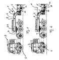
- a heavy load vehicle 1 which is coupled via a gooseneck 2 with a towing vehicle 3, between a chassis of the heavy load vehicle 1 and the gooseneck 2, at least one displacer 4.
- a towing vehicle 3 between a chassis of the heavy load vehicle 1 and the gooseneck 2, at least one displacer 4.
- a heavy load vehicle 1 which is coupled via a gooseneck 2 with a towing vehicle 3, between a chassis of the heavy load vehicle 1 and the gooseneck 2, at least one displacer 4.
- axis line A is shown, wherein such heavy-duty vehicles 1 normally have further arranged in the direction of travel behind this axis line A axle lines.
- large loads such as construction machines, can be transported.
- the tractor 3 according to the embodiments of the Fig. 1 and 2 a total of four axes, wherein at least the frontmost axis in the direction of travel is equipped with steerable wheels 6.
- the towing vehicle 3 is coupled to the heavy load vehicle 1, wherein an over the gooseneck 2 acting on the towing vehicle 3 fifth wheel load determines the axle loads of the towing vehicle 3 and thus its traction.
- the prevailing in the displacer 4 pressure is determined by the load to be transported.
- the gooseneck 2 is according to the Fig. 1 and 2 about a substantially parallel to the axes of the towing vehicle 3 and the heavy load vehicle 1 extending axis 8 (perpendicular to the image plane) bendable.
- the buckling possibility is thereby in the consideration of Fig. 2 unlike Fig. 1 clear.
- a buckling counterclockwise is possible.
- this is coupled to the towing vehicle 3 via the coupling 7, whereas it is pivotally connected to the puller 3 remote end 22 to the displacer 4.
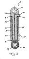
- Fig. 3 has the displacer 4 constructed as a 3-area lifting cylinder two positive chambers 9 and 9 'and a negative chamber 10, which are acted upon in a predeterminable combination with hydraulic medium.
- the two positive chambers 9, 9 'and the negative chamber 10 have different cross-sectional areas.
- An increase in the hydraulic volume in the positive chambers 9 and 9 ' causes at the same time unpressurized negative chamber 10, an extension of the displacer 4, whereas a pressure medium supply into the negative chamber 10 at the same time unpressurized positive chambers 9 causes a shortening or a contraction of the displacer 4.
- the displacer assembly 4 consists of a first displacer part 12 and a cooperating second displacer part 13 and preferably has a substantially cylindrical shape.
- each of the displacer parts 12, 13 each have a bearing eye 14, via which the displacer assembly 4 can be articulated, for example, by means of a bolt on the gooseneck 2 or on the heavy-duty vehicle 1.
- the first displacer part 12 has a tubular piston rod 15 with an annular piston 16 arranged at the end and facing the second displacer part 13.
- the annular piston 16 is displaceably arranged in an annular space 17 of the second displacer part 13, which simultaneously forms the negative chamber 10, and separates according to FIG Fig. 3 the positive chamber 9 from the negative chamber 10th
- the second displacer part 13 has a plunger-like piston 18, which is displaceably mounted in the tube interior in the piston rod 15 of the first displacer part 12.
- the first displacement member 12 and the plunger-like piston 18 thereby limit the second positive chamber 9 ', wherein a hydraulic Supply line to the second positive chamber 9 'substantially centrally in the plunger-like piston 18 extends close to the recess 14 and is then guided radially outwardly to the connecting line 11'.
- the negative chamber 10 is connected via a connecting line 11 "to the hydraulic system.
- the displacer assembly 4 with hydraulic Radabstützaggregaten 19 of the vehicle wheels 20 of the heavy load vehicle 1 is pressure-connected (see. Fig. 1 ).
- a load to be transported on the bed 5 of the heavy duty vehicle 1 determines the pressure in the hydraulic Radabstützaggregaten 19 and thus also a hydraulic pressure in the displacer 4.
- the so predetermined on the load to be transported hydraulic pressure in the displacer 4 again determines the gooseneck 2 to the coupling 7 and the towing vehicle 3 to be transmitted fifth wheel load.
- the fifth wheel load is dependent on the load to be transported and no longer dependent on a selected for the displacement assembly 4 articulation point on the gooseneck 2. It is possible depending on the desired height level to pump a larger or smaller hydraulic volume in the Radabstützaggregate 19 of the vehicle wheels 20 ,
- the displacer 4 is connected via a valve assembly 24 with the Radabstützaggregaten 19.
- the wheel support units 19 can be interconnected into three independent groups, resulting in the best case, a three-point support of the heavy truck 1 results on the road.
- a three-point support can be done, for example, by interconnecting a plurality of front axle lines of the heavy load vehicle 1 in the direction of travel and by a page-wise interconnection of the axis lines of the heavy load vehicle 1 located behind in the direction of travel.
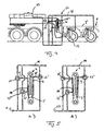
- Fig. 4 a possible mounting form of the displacer 4 is shown on the gooseneck 2, wherein each displacer assembly 4 is connected via connecting lines 11 both with a substantially unpressurized hydraulic reservoir 23 and with at least two Radabstützaggregaten 19.
- Each positive chamber 9 and 9 'and the negative chamber 10 is preceded by an associated valve 25, which is part of the valve assembly 24, so that the individual positive chambers 9 and 9' and the negative chamber 10 are connected to the hydraulic system or be separated from it can.
- the hydraulic pressure prevailing in the hydraulic system or in the connecting lines 11 is determined by the dead weight of the heavy-duty vehicle 1 or by a load to be transported on its loading surface 5.
- the over the gooseneck 2 to the towing vehicle 3 to be transmitted to the fifth wheel load on the position of the valves 25, 25 ', 25 are influenced, so that always the required axle for traction axle load is reached.
- the valves 25th and 25 'set so that the two positive chambers 9 and 9' can be acted upon with hydraulic medium, while the negative chamber 10 with the pressure-less in itself and according to the Fig. 5a not shown hydraulic reservoir 23 is connected.
- the two positive chambers 9 and 9 ' act together.
- valves 25, 25', 25 can thus only by a simple change in the valve positions six different actuating forces in the displacer 4.
- the valves 25, 25 ', 25 may in this case be from a closed to a fully opened, partially open position Condition are transferred and vice versa.
- valves 25, 25 'and 25 “and the different cross-sectional areas of the two positive chambers 9, 9' and the negative chamber 10 it is possible to generate different fifth-wheel loads which are adapted to the respective tractor 3 and for a sufficient axle load the driven axles so that the towing vehicle 3 can transmit the traction force reliably to the roadway, whereby the number of axles of the towing vehicle can also be taken into account.
Description
Die Erfindung betrifft ein Schwerstlastfahrzeug mit
- einem zur Kupplung des Schwerstlastfahrzeuges an ein Zugfahrzeug auf das Zugfahrzeug aufsattelbaren Schwanenhals,
- einer dem Schwanenhals zugeordneten hydraulischen Verdrängeranordnung, deren Hydraulikdrücke die vom Schwanenhals auf das Zugfahrzeug abgetragene Last bestimmen, und
- mehreren hydraulisch mit der Verdrängeranordnung kommunizierenden und damit die Hydraulikdrücke in der Verdrängeranordnung bestimmenden Radabstützaggregaten.
- a gooseneck which can be mounted on the towing vehicle for coupling the heavy load vehicle to a towing vehicle,
- a hydraulic displacer arrangement associated with the gooseneck, the hydraulic pressures of which determine the load removed by the gooseneck on the towing vehicle, and
- a plurality of Radabstützaggregaten communicating hydraulically with the displacer arrangement and thus determining the hydraulic pressures in the displacer arrangement.
Ein derartiges Schwerstlastfahrzeug ist aus der
Die
Aus der
Nach der
Aus der
Die Erfindung steht im Zusammenhang mit dem Problem, das Verhältnis zwischen der auf das Zugfahrzeug abgetragenen Last und den Radlasten derjenigen Räder des Schwerstlastfahrzeuges, die den mit der Verdrängeranordnung des Schwanenhalses kommunizierenden Radabstützaggregaten zugeordnet sind, verändern zu können. Bei bisher auf dem Markt erhältlichen Schwerstlastfahrzeugen ist zu diesem Zweck vorgesehen, die Verdrängeranordnung am Schwanenhals in unterschiedlichen Positionen anzubringen, derart, dass das Übersetzungsverhältnis zwischen dem hydraulischen Druck in der Verdrängeranordnung und der auf das Zugfahrzeug abgetragenen Last verändert wird. Dabei ist jedoch problematisch, dass die Montage der Verdrängeranordnung fehlerhaft erfolgen kann und insofern mit schweren Schäden am Schwerstlastfahrzeug gerechnet werden muss. Dementsprechend ist es Aufgabe der Erfindung, eine Anordnung zu schaffen, mit der sich das Verhältnis zwischen der auf das Zugfahrzeug abgetragenen Last und den Radlasten mit hoher Betriebssicherheit verändern bzw. einstellen lässt.The invention is related to the problem of being able to alter the relationship between the load borne by the towing vehicle and the wheel loads of those wheels of the heavy duty vehicle associated with the wheel support assemblies communicating with the displacer assembly of the gooseneck. In hitherto available on the market heavy duty vehicles is provided for this purpose, to install the displacer assembly on the gooseneck in different positions, such that the transmission ratio between the hydraulic pressure in the displacer assembly and the load carried on the towing vehicle is changed. However, it is problematic that the assembly of the displacer can be done incorrectly and thus must be reckoned with serious damage to the heavy truck. Accordingly, it is the object of the invention to provide an arrangement with which the ratio between the load carried by the towing vehicle and the wheel loads can be changed or adjusted with high reliability.
Diese Aufgabe wird bei einem Schwerstlastfahrzeug der eingangs angegebenen Art erfindungsgemäß dadurch gelöst, dass die Verdrängeranordnung Positiv- und Negativkammern aufweist, wobei die Hydraulikdrücke in den Positivkammern zu Stellkräften führen, die den von den Hydraulikdrücken in den Negativkammern bewirkten Stellkräften entgegenwirken, so dass durch die Positiv- und Negativkammern erzeugten Hydraulikdrücke einander entgegengerichtete Kräfte in Zug-oder Schubrichtung der Verdrängeranordnung bewirken, und die in vorgebbarer Kombination mit den Radabstützaggregaten und/oder einem relativ drucklosen Hydraulikreservoir verbindbar sind, dass die Verdrängeranordnung ein erstes und ein zweites Verdrängerteil aufweist,
dass das erste Verdrängerteil eine rohrförmige Kolbenstange mit einem endseitig daran angeordneten und dem zweiten Verdrängerteil zugewandten Ringkolben aufweist, der in einem Ringraum des zweiten Verdrängerteils verschiebbar angeordnet ist und dabei eine erste Arbeitskammer von einer zweiten Arbeitskammer trennt,
dass die erste Arbeitskammer eine der beiden Positivkammern und die zweite Arbeitskammer die Negativkammer bildet und
dass das zweite Verdrängerteil einen plungerartigen Kolben aufweist, welcher im Rohrinnenraum in der Kolbenstange des ersten Verdrängerteils verschiebbar gelagert ist, und
dass das erste Verdrängerteil und der plungerartige Kolben des zweiten Verdrängerteils eine dritte Arbeitkammer begrenzen,
wobei die dritte Arbeitskammer die zweite Positivkammer bildet, und dass die Verdrängeranordnung über eine Ventilanordnung mit zumindest einem Ventil direkt oder indirekt mit zumindest einem Radabstützaggregat oder einem Hydraulikreservoir verbindbar ist.This object is achieved in a heavy load vehicle of the type specified according to the invention that the positive displacement and negative chambers, wherein the hydraulic pressures in the positive chambers lead to actuating forces, which counteract the actuation forces caused by the hydraulic pressures in the negative chambers, so that by the positive - And negative chambers generated hydraulic pressures cause opposing forces in the tensile or shear direction of the displacer, and in specifiable combination with the Radabstützaggregaten and / or a relatively pressureless Hydraulic reservoir are connectable, that the displacer arrangement comprises a first and a second displacer part,
the first displacer part has a tubular piston rod with an annular piston arranged at the end and facing the second displacer part, said piston being displaceably arranged in an annular space of the second displacer part, thereby separating a first working chamber from a second working chamber,
that the first working chamber forms one of the two positive chambers and the second working chamber forms the negative chamber and
that the second displacer part has a plunger-like piston which is displaceably mounted in the tube interior in the piston rod of the first displacer part, and
the first displacement part and the plunger-like piston of the second displacement part define a third working chamber,
wherein the third working chamber forms the second positive chamber, and that the displacer arrangement via a valve arrangement with at least one valve directly or indirectly with at least one Radabstützaggregat or a hydraulic reservoir is connectable.
Die Erfindung beruht also auf dem allgemeinen Gedanken, die dem Schwanenhals zugeordnete Verdrängeranordnung als Mehrkammersystem auszubilden, wobei die Hydraulikdrücke in den einen Kammern (Positivkammern) zu Stellkräften führen, die den von den Hydraulikdrücken in anderen Kammern (Negativkammern) bewirkten Stellkräften entgegenwirken. Bei der Erfindung wird also lediglich eine Umschaltventilanordnung benötigt, um die verschiedenen Kammern der Verdrängeranordnung in unterschiedlicher Kombination entweder mit dem relativ drucklosen Hydraulikreservoir oder den Radabstützaggregaten zu verbinden. Fehlbedienungen oder gar Fehlmontagen sind damit ausgeschlossen.The invention is thus based on the general idea of designing the displacer arrangement associated with the gooseneck as a multi-chamber system, wherein the hydraulic pressures in the one chambers (positive chambers) lead to actuating forces which counteract the actuating forces caused by the hydraulic pressures in other chambers (negative chambers). In the invention, therefore, only one Umschaltventilanordnung is required to connect the various chambers of the displacer in different combinations either with the relatively pressureless hydraulic reservoir or the Radabstützaggregaten. Operating errors or even incorrect assembly are thus excluded.
Die Verdrängeranordnung weist erfindungsgemäß eine erste und eine davon fluidisch trennbare zweite Positivkammer auf. Dies bietet den großen Vorteil, hohe Abstützlasten der Verdrängeranordnung durch ein Verbinden, d.h. ein Parallelschalten, der beiden Positivkammern zu realisieren, während geringe Abstützlasten durch Druckmittelzufuhr zu lediglich einer der beiden Positivkammern zu erreichen sind.According to the invention, the displacer arrangement has a first and a second positive chamber which can be fluidly separated therefrom. This offers the big advantage, high Support loads of the displacer assembly by a connection, ie a parallel switching, the two positive chambers to realize while low support loads can be achieved by supplying pressure medium to only one of the two positive chambers.
Bei der erfindungsgemäßen Lösung ist die Verdrängeranordnung mit hydraulischen Radabstützaggregaten der Fahrzeugräder druckverbunden. Dies bewirkt, dass die von der Verdrängeranordnung erzeugte Sattellast abhängig ist von der von dem Schwerstlastfahrzeug aufgenommenen zu transportierenden Last. Hohe Lasten bedeuten somit einen hohen Druck in den Radabstützaggregaten und gleichzeitig einen hohen Druck in der Verdrängeranordnung, welche dann über den Schwanenhals eine zu der zu transportierenden großen Last entsprechend hohe Sattellast erzeugt. Die Sattellast wiederum ist verantwortlich für die Achslast des Zugfahrzeuges, so dass durch die Druckverbindung zwischen der Verdrängeranordnung und den Radabstützaggregaten des Schwerstlastfahrzeuges die Achslast des Zugfahrzeuges und damit dessen Traktion mit einer Fahrbahn bestimmt werden kann.In the solution according to the invention, the displacer assembly is pressure-connected to hydraulic Radabstützaggregaten the vehicle wheels. This causes the fifth wheel load generated by the displacer assembly to be dependent on the load to be transported picked up by the heavy load vehicle. High loads thus mean high pressure in Radabstützaggregaten and at the same time a high pressure in the displacer assembly, which then generates a correspondingly high saddle load over the gooseneck to the large load to be transported. The fifth-wheel load in turn is responsible for the axle load of the towing vehicle, so that the axle load of the towing vehicle and thus its traction with a roadway can be determined by the pressure connection between the displacer assembly and the Radabstützaggregaten the heavy load vehicle.
Weitere wichtige Merkmale und Vorteile der Erfindung ergeben sich aus den Unteransprüchen, aus den Zeichnungen und aus der zugehörigen Figurenbeschreibung anhand der Zeichnungen.Other important features and advantages of the invention will become apparent from the dependent claims, from the drawings and from the associated figure description with reference to the drawings.
Es versteht sich, dass die vorstehend genannten und die nachstehend noch zu erläuternden Merkmale nicht nur in der jeweils angegebenen Kombination, sondern auch in anderen Kombinationen oder in Alleinstellung verwendbar sind, ohne den Rahmen der vorliegenden Erfindung zu verlassen.It is understood that the features mentioned above and those yet to be explained below can be used not only in the particular combination given, but also in other combinations or in isolation, without departing from the scope of the present invention.
Bevorzugte Ausführungsbeispiele der Erfindung sind in den Zeichnungen dargestellt und werden in der nachfolgenden Beschreibung näher erläutert, wobei sich gleiche Bezugszeichen auf gleiche oder funktional gleiche oder ähnliche Bauteile beziehen.Preferred embodiments of the invention are illustrated in the drawings and will be described in more detail in the following description, wherein like reference numerals refer to identical or functionally identical or similar components.
Dabei zeigen, jeweils schematisch,
- Fig. 1
- eine Seitenansicht eines mit einem Zugfahrzeug über einen Schwanenhals gekuppelten Schwerstlastfahrzeugs,
- Fig. 2
- eine Darstellung wie in
Fig. 1 , jedoch mit geneigtem Schwanenhals, - Fig. 3
- eine schematische Schnittsdarstellung einer erfindungsgemäßen Verdrängeranordnung,
- Fig. 4
- einen Ausschnitt einer Seitenansicht im Bereich des Schwanenhalses mit einem möglichen Hydrauliksystem,
- Fig. 5a-f
- eine Schnittdarstellung der Verdrängeranordnung bei unterschiedlichen Ventilstellungen.
- Fig. 1
- a side view of a coupled to a towing vehicle via a gooseneck heavy load vehicle,
- Fig. 2
- a representation like in
Fig. 1 but with a gooseneck, - Fig. 3
- a schematic sectional view of a Verdrängeranordnung invention,
- Fig. 4
- a section of a side view in the area of the gooseneck with a possible hydraulic system,
- Fig. 5a-f
- a sectional view of the displacer assembly at different valve positions.
Entsprechend
Das Zugfahrzeug 3 weist gemäß den Ausführungsbeispielen der
Der Schwanenhals 2 ist entsprechend den
Gemäß
Generell besteht die Verdrängeranordnung 4 aus einem ersten Verdrängerteil 12 und einem damit zusammenwirkenden zweiten Verdrängerteil 13 und weist vorzugsweise eine im wesentliche zylindrische Form auf. Darüber hinaus weist jedes der Verdrängerteile 12, 13 jeweils ein Lagerauge 14 auf, über welches die Verdrängeranordnung 4 beispielsweise mittels eines Bolzens am Schwanenhals 2 bzw. am Schwerstlastfahrzeug 1 anlenkbar ist.Generally, the
Das erste Verdrängerteil 12 besitzt eine rohrförmige Kolbenstange 15 mit einem endseitig daran angeordneten und dem zweiten Verdrängerteil 13 zugewandeten Ringkolben 16. Der Ringkolben 16 ist dabei in einem Ringraum 17 des zweiten Verdrängerteils 13 verschiebbar angeordnet, der gleichzeitig die Negativkammer 10 bildet, und trennt gemäß
Das zweite Verdrängerteil 13 weist einen plungerartigen Kolben 18 auf, welcher im Rohrinnenraum in der Kolbenstange 15 des ersten Verdrängerteils 12 verschiebbar gelagert ist. Das erste Verdrängerteil 12 und der plungerartige Kolben 18 begrenzen dabei die zweite Positivkammer 9', wobei eine hydraulische Zuleitung zur zweiten Positivkammer 9' im wesentlichen zentral im plungerartigen Kolben 18 nahe bis zur Ausnehmung 14 verläuft und dann radial nach außen hin zur Anschlussleitung 11' geführt ist. Die Negativkammer 10 ist über eine Anschlussleitung 11" an das hydraulische System angeschlossen.The second displacer part 13 has a plunger-
Gemäß der Erfindung ist die Verdrängeranordnung 4 mit hydraulischen Radabstützaggregaten 19 der Fahrzeugräder 20 des Schwerstlastfahrzeugs 1 druckverbunden (vgl.
Um eine möglichst stabile und an eventuelle Unebenheiten einer Fahrbahn angepasste Straßenlage des Schwerstlastfahrzeugs 1 zu gewährleisten, sind die Radabstützaggregate 19 zu drei voneinander unabhängigen Gruppen zusammenschaltbar, woraus sich günstigsten Falls eine Dreipunktabstützung des Schwerstlastfahrzeuges 1 auf der Fahrbahn ergibt. Eine derartige Dreipunktabstützung kann beispielsweise durch Zusammenschalten mehrerer in Fahrtrichtung vorne gelegenen Achslinien des Schwerstlastfahrzeuges 1 sowie durch ein seitenweises Zusammenschalten der in Fahrtrichtung dahinter gelegenen Achslinien des Schwerstlastfahrzeugs 1 erfolgen.In order to ensure the most stable road position of the heavy-duty vehicle 1 adapted to possible unevenness of a roadway, the
In
In den
Demgegenüber bewirkt eine Ventilstellung gemäß
In der
In der Darstellung gemäß
Mit der erfindungsgemäßen Ausbildung der Verdrängeranordnung 4 als Drei-Flächen-Hubzylinder mit zwei Positivkammern 9 und 9' und einer Negativkammer 10 sowie jeweils zugeordneten Ventilen 25, 25' und 25" können somit nur durch eine einfache Änderung der Ventilstellungen sechs verschiedene Stellkräfte in der Verdrängeranordnung 4 realisiert werden. Die Ventile 25, 25', 25" können dabei von einem geschlossenen über einen teilweise geöffneten in einen vollständig geöffneten Zustand überführt werden und umgekehrt. Über die erfindungsgemäße Anordnung der Ventile 25, 25' und 25" und die unterschiedlichen Querschnittsflächen der zwei Positivkammern 9, 9'und der Negativkammer 10 ist es möglich, unterschiedliche Sattellasten zu generieren, welche angepasst an die jeweilige Zugmaschine 3 und für eine ausreichende Achslast auf den angetriebenen Achsen sorgen, damit das Zugfahrzeug 3 die Zugkraft zuverlässig auf die Fahrbahn übertragen kann. Dabei kann auch die Anzahl der Achsen des Zugfahrzeugs berücksichtigt werden.With the inventive design of the
Claims (4)
- Heavy load truck (1) having- a goose neck that can be hitched up on a towing vehicle for coupling the heavy load truck (1) with the towing vehicle (3),- a hydraulic displacer unit (4) associated to the goose neck (2), the hydraulic pressures of which determine the loads transferred from the goose neck (2) to the towing vehicle (3), and- a plurality of wheel supporting units (19) in fluidic communication with the displacer unit (4), which thus determine the hydraulic pressures in the displaces unit (4),characterized in- that the displacer unit (4) comprises positive and negative chambers (9, 9'; 10), which can be connected in predefinable combination with the wheel supporting units (19) and/or a relatively pressureless hydraulic reservoir (23), the hydraulic pressures in the positive chambers producing displacing forces that counteract the displacing forces resulting from the hydraulic pressures in the negative chambers so that the hydraulic pressures produced by the positive and negative chambers (9, 9'; 10) result in oppositely directed hydraulic pressures acting in the direction of thrust and/or in the direction of pull of the displacer unit (4),- that the displacer unit (4) comprises a first (12) and a second displacer element (13),- that the first displacer element (12) comprises a tubular piston rod (15) with an annular piston (16) which is provided on its one end facing the second displacer element (13) and which is arranged for displacement in an annular space (17) of the second displacer element (13) thereby separating a first working chamber from a second working chamber;- that the first working chamber constitutes one of the two positive chambers (9, 9') and the second working chamber constitutes the negative chamber (10), and- that the second displacer element (13) comprises a plunger-like piston (18) accommodated for displacement in the tubular interior of the piston rod (15) of the first displacer element (12), and- that the first displacer element (12) and the plunger-like piston (18) of the second displacer element (13) delimit a third working chamber,- the third working chamber constituting the second positive chamber (9'), and that the displacer unit (4) can be connected with at least one wheel supporting unit (19) or one hydraulic reservoir directly or indirectly, via a valve arrangement (24) having at least one valve (25).
- The heavy load truck as defined in Claim 1,
characterized in that the displacer unit (4) comprises a first (9) and a second positive chamber (9') that can be separated from said first chamber in fluidic respect. - The heavy load truck as defined in Claim 1 or Claim 2,
characterized in that the heavy load truck (1) comprises at least two vehicle modules that can be coupled one with the other, and that one of the vehicle modules carries the goose neck. - The heavy load truck as defined in any of Claims 1 to 3,
characterized in that the wheel supporting unit (19) of the heavy load truck (1) can be connected to form three groups one independent from the other in order to permit a three-point contact to be realized between the heavy load truck (1) and the road.
Applications Claiming Priority (1)
| Application Number | Priority Date | Filing Date | Title |
|---|---|---|---|
| DE200610004930 DE102006004930A1 (en) | 2006-02-03 | 2006-02-03 | With a towing vehicle via a gooseneck detachable heavy load vehicle |
Publications (2)
| Publication Number | Publication Date |
|---|---|
| EP1816059A1 EP1816059A1 (en) | 2007-08-08 |
| EP1816059B1 true EP1816059B1 (en) | 2009-02-25 |
Family
ID=37969909
Family Applications (1)
| Application Number | Title | Priority Date | Filing Date |
|---|---|---|---|
| EP20070101457 Active EP1816059B1 (en) | 2006-02-03 | 2007-01-31 | Super-heavy lorry coupled to a tractor through a gooseneck |
Country Status (3)
| Country | Link |
|---|---|
| EP (1) | EP1816059B1 (en) |
| DE (2) | DE102006004930A1 (en) |
| ES (1) | ES2323093T3 (en) |
Families Citing this family (6)
| Publication number | Priority date | Publication date | Assignee | Title |
|---|---|---|---|---|
| DE202009005380U1 (en) | 2009-04-09 | 2010-01-14 | Scheuerle Fahrzeugfabrik Gmbh | Gooseneck for a truck, especially for a heavy duty vehicle |
| EP2239188B9 (en) | 2009-04-09 | 2012-08-15 | Scheuerle Fahrzeugfabrik GmbH | Goose-neck for a vehicle, especially for a heavy duty vehicle |
| DE102009016725B4 (en) | 2009-04-09 | 2012-02-16 | Scheuerle Fahrzeugfabrik Gmbh | Gooseneck for a vehicle, especially for a heavy vehicle |
| DE202017001550U1 (en) | 2017-03-23 | 2018-06-28 | Scheuerle Fahrzeugfabrik Gmbh | Control unit for a control device for a heavy-duty vehicle, in particular for a gooseneck, a lifting arrangement or a steering arrangement of a heavy-duty vehicle, and such a control device |
| EP3601807B1 (en) | 2017-03-23 | 2021-05-19 | Scheuerle Fahrzeugfabrik GmbH | Control unit for a control device for a heavy duty vehicle, especially for a swan neck arm, a lift arrangement or a steering arrangement of a heavy duty vehicle, and such a control device |
| DE102017002784A1 (en) | 2017-03-23 | 2018-09-27 | Scheuerle Fahrzeugfabrik Gmbh | Control unit for a control device for a heavy-duty vehicle, in particular for a gooseneck, a lifting arrangement or a steering arrangement of a heavy-duty vehicle, and such a control device |
Family Cites Families (5)
| Publication number | Priority date | Publication date | Assignee | Title |
|---|---|---|---|---|
| US2475443A (en) * | 1948-05-17 | 1949-07-05 | Robert O Bill | Semitrailer with body elevating and lowering means |
| AT328300B (en) | 1973-07-24 | 1976-03-10 | Goldhofer Fahrzeugwerk Kg | VEHICLE WITH A TRACTOR AND A TRAILER |
| FR2384665A1 (en) * | 1977-03-24 | 1978-10-20 | Nicolas France Sa Jb | SEMI-TRAILER HITCH IMPROVEMENTS |
| ES2038890B1 (en) * | 1991-05-10 | 1994-02-16 | Santamaria Felix Fernandez | DEVICE TO VARY THE LOAD ON THE TRACTION WHEELS OF A VEHICLE. |
| FR2870200B1 (en) | 2004-05-13 | 2007-08-24 | Nicolas Ind | INTEGRATED AXLE SOCKET (S) FOR A SEMI-TRAILER |
-
2006
- 2006-02-03 DE DE200610004930 patent/DE102006004930A1/en not_active Withdrawn
-
2007
- 2007-01-31 EP EP20070101457 patent/EP1816059B1/en active Active
- 2007-01-31 ES ES07101457T patent/ES2323093T3/en active Active
- 2007-01-31 DE DE200750000450 patent/DE502007000450D1/en active Active
Also Published As
| Publication number | Publication date |
|---|---|
| EP1816059A1 (en) | 2007-08-08 |
| DE502007000450D1 (en) | 2009-04-09 |
| DE102006004930A1 (en) | 2007-08-16 |
| ES2323093T3 (en) | 2009-07-06 |
Similar Documents
| Publication | Publication Date | Title |
|---|---|---|
| EP2238071B1 (en) | Wheeled working machine | |
| EP2240360B1 (en) | Mobile working machine | |
| EP1816059B1 (en) | Super-heavy lorry coupled to a tractor through a gooseneck | |
| EP0544727A1 (en) | Vehicle. | |
| EP0266785A1 (en) | Self-propelled multipurpose device | |
| WO2019012045A2 (en) | Axle assembly for a heavy-goods vehicle, heavy-goods vehicle with at least one such axle assembly and a hydraulic unit, in particular for adjusting an adjustable unit designed as a cylinder-piston arrangement | |
| DE2546485C3 (en) | Road vehicle with lowerable loading area | |
| EP1918137A2 (en) | Airport tow vehicle with pneumatic suspension | |
| EP3427560B1 (en) | Towing device | |
| DE1605068C3 (en) | Tractor for use on rail and road | |
| EP2239188B9 (en) | Goose-neck for a vehicle, especially for a heavy duty vehicle | |
| WO2020025201A1 (en) | Combination having a tractor and a semi-trailer, tractor, semi-trailer and method for axle load distribution in a combination | |
| DE202012102356U1 (en) | Trailer vehicle with articulated drawbar | |
| EP3156310B1 (en) | Drive-less agricultural auxiliary vehicle | |
| DE1932040A1 (en) | Weight transmission coupling | |
| EP3909407A1 (en) | Towed agricultural working machine and method for influencing the supporting force of a towed agricultural working machine | |
| DE3404930C2 (en) | Motor vehicle articulated train | |
| EP3971066B1 (en) | Tractor with caterpillar track | |
| DE3239006A1 (en) | VEHICLE WITH A BODY PART WHICH CAN BE SWIVELED A HORIZONTAL AXLE AND IS SUPPORTED BY A HYDROPNEUMATIC SUSPENSION | |
| DE102009040204B4 (en) | Chassis device with an axle lift unit | |
| DE202009005380U1 (en) | Gooseneck for a truck, especially for a heavy duty vehicle | |
| DE102009016725B4 (en) | Gooseneck for a vehicle, especially for a heavy vehicle | |
| AT392444B (en) | All-terrain two- or multi-axle utility vehicle with rubber tyres | |
| DE10215033A1 (en) | Agricultural trailer vehicle with load displacement device has pressure medium pressure limited to value that enables second axle to be lowered only if trailer vehicle is partly unloaded | |
| DE202008015664U1 (en) | Front-axle runner for receiving semitrailers |
Legal Events
| Date | Code | Title | Description |
|---|---|---|---|
| PUAI | Public reference made under article 153(3) epc to a published international application that has entered the european phase |
Free format text: ORIGINAL CODE: 0009012 |
|
| AK | Designated contracting states |
Kind code of ref document: A1 Designated state(s): AT BE BG CH CY CZ DE DK EE ES FI FR GB GR HU IE IS IT LI LT LU LV MC NL PL PT RO SE SI SK TR |
|
| AX | Request for extension of the european patent |
Extension state: AL BA HR MK YU |
|
| 17P | Request for examination filed |
Effective date: 20070825 |
|
| 17Q | First examination report despatched |
Effective date: 20071016 |
|
| AKX | Designation fees paid |
Designated state(s): BE DE ES FR IT NL |
|
| GRAP | Despatch of communication of intention to grant a patent |
Free format text: ORIGINAL CODE: EPIDOSNIGR1 |
|
| GRAS | Grant fee paid |
Free format text: ORIGINAL CODE: EPIDOSNIGR3 |
|
| GRAA | (expected) grant |
Free format text: ORIGINAL CODE: 0009210 |
|
| AK | Designated contracting states |
Kind code of ref document: B1 Designated state(s): BE DE ES FR IT NL |
|
| REF | Corresponds to: |
Ref document number: 502007000450 Country of ref document: DE Date of ref document: 20090409 Kind code of ref document: P |
|
| REG | Reference to a national code |
Ref country code: ES Ref legal event code: FG2A Ref document number: 2323093 Country of ref document: ES Kind code of ref document: T3 |
|
| PLBE | No opposition filed within time limit |
Free format text: ORIGINAL CODE: 0009261 |
|
| STAA | Information on the status of an ep patent application or granted ep patent |
Free format text: STATUS: NO OPPOSITION FILED WITHIN TIME LIMIT |
|
| 26N | No opposition filed |
Effective date: 20091126 |
|
| PGFP | Annual fee paid to national office [announced via postgrant information from national office to epo] |
Ref country code: NL Payment date: 20101221 Year of fee payment: 5 |
|
| PGFP | Annual fee paid to national office [announced via postgrant information from national office to epo] |
Ref country code: FR Payment date: 20110201 Year of fee payment: 5 Ref country code: IT Payment date: 20110129 Year of fee payment: 5 |
|
| PGFP | Annual fee paid to national office [announced via postgrant information from national office to epo] |
Ref country code: BE Payment date: 20110124 Year of fee payment: 5 |
|
| PGFP | Annual fee paid to national office [announced via postgrant information from national office to epo] |
Ref country code: ES Payment date: 20110121 Year of fee payment: 5 |
|
| BERE | Be: lapsed |
Owner name: SCHEUERLE FAHRZEUGFABRIK G.M.B.H. Effective date: 20120131 |
|
| REG | Reference to a national code |
Ref country code: NL Ref legal event code: V1 Effective date: 20120801 |
|
| REG | Reference to a national code |
Ref country code: FR Ref legal event code: ST Effective date: 20120928 |
|
| PG25 | Lapsed in a contracting state [announced via postgrant information from national office to epo] |
Ref country code: IT Free format text: LAPSE BECAUSE OF NON-PAYMENT OF DUE FEES Effective date: 20120131 |
|
| PG25 | Lapsed in a contracting state [announced via postgrant information from national office to epo] |
Ref country code: FR Free format text: LAPSE BECAUSE OF NON-PAYMENT OF DUE FEES Effective date: 20120131 Ref country code: BE Free format text: LAPSE BECAUSE OF NON-PAYMENT OF DUE FEES Effective date: 20120131 |
|
| PG25 | Lapsed in a contracting state [announced via postgrant information from national office to epo] |
Ref country code: NL Free format text: LAPSE BECAUSE OF NON-PAYMENT OF DUE FEES Effective date: 20120801 |
|
| REG | Reference to a national code |
Ref country code: ES Ref legal event code: FD2A Effective date: 20131021 |
|
| PG25 | Lapsed in a contracting state [announced via postgrant information from national office to epo] |
Ref country code: ES Free format text: LAPSE BECAUSE OF NON-PAYMENT OF DUE FEES Effective date: 20120201 |
|
| PGFP | Annual fee paid to national office [announced via postgrant information from national office to epo] |
Ref country code: DE Payment date: 20230329 Year of fee payment: 17 |
|
| P01 | Opt-out of the competence of the unified patent court (upc) registered |
Effective date: 20230515 |