EP2772173A1 - Filterbeutel für einen Staubsauger und Verfahren zur Herstellung einer Halteplatte für einen Filterbeutel - Google Patents
Filterbeutel für einen Staubsauger und Verfahren zur Herstellung einer Halteplatte für einen Filterbeutel Download PDFInfo
- Publication number
- EP2772173A1 EP2772173A1 EP14154787.7A EP14154787A EP2772173A1 EP 2772173 A1 EP2772173 A1 EP 2772173A1 EP 14154787 A EP14154787 A EP 14154787A EP 2772173 A1 EP2772173 A1 EP 2772173A1
- Authority
- EP
- European Patent Office
- Prior art keywords
- holding plate
- filter bag
- collar
- filter
- filter material
- Prior art date
- Legal status (The legal status is an assumption and is not a legal conclusion. Google has not performed a legal analysis and makes no representation as to the accuracy of the status listed.)
- Granted
Links
- 238000004519 manufacturing process Methods 0.000 title claims description 6
- 239000000463 material Substances 0.000 claims abstract description 47
- 239000012065 filter cake Substances 0.000 claims abstract description 10
- 230000015572 biosynthetic process Effects 0.000 claims abstract description 4
- 238000000034 method Methods 0.000 claims description 3
- 238000007789 sealing Methods 0.000 claims description 3
- 230000006735 deficit Effects 0.000 abstract 1
- 238000001914 filtration Methods 0.000 description 4
- 238000004026 adhesive bonding Methods 0.000 description 3
- 238000003466 welding Methods 0.000 description 2
- 239000000853 adhesive Substances 0.000 description 1
- 230000001070 adhesive effect Effects 0.000 description 1
- 238000005452 bending Methods 0.000 description 1
- 239000011248 coating agent Substances 0.000 description 1
- 238000000576 coating method Methods 0.000 description 1
- 238000011109 contamination Methods 0.000 description 1
- 239000000428 dust Substances 0.000 description 1
- 238000002474 experimental method Methods 0.000 description 1
- 210000003746 feather Anatomy 0.000 description 1
- 238000002347 injection Methods 0.000 description 1
- 239000007924 injection Substances 0.000 description 1
- 239000004745 nonwoven fabric Substances 0.000 description 1
- 230000003014 reinforcing effect Effects 0.000 description 1
- 238000003892 spreading Methods 0.000 description 1
Images


Classifications
-
- A—HUMAN NECESSITIES
- A47—FURNITURE; DOMESTIC ARTICLES OR APPLIANCES; COFFEE MILLS; SPICE MILLS; SUCTION CLEANERS IN GENERAL
- A47L—DOMESTIC WASHING OR CLEANING; SUCTION CLEANERS IN GENERAL
- A47L9/00—Details or accessories of suction cleaners, e.g. mechanical means for controlling the suction or for effecting pulsating action; Storing devices specially adapted to suction cleaners or parts thereof; Carrying-vehicles specially adapted for suction cleaners
- A47L9/10—Filters; Dust separators; Dust removal; Automatic exchange of filters
- A47L9/14—Bags or the like; Rigid filtering receptacles; Attachment of, or closures for, bags or receptacles
- A47L9/1427—Means for mounting or attaching bags or filtering receptacles in suction cleaners; Adapters
- A47L9/1436—Connecting plates, e.g. collars, end closures
- A47L9/1445—Connecting plates, e.g. collars, end closures with closure means
- A47L9/1454—Self-sealing closures, e.g. valves
Definitions
- the present invention relates to a filter bag with a filter material, in which an inlet opening is provided, and a holding plate arranged on the inlet opening, which is attachable to a holding device of a vacuum cleaner for holding the filter bag, wherein on the holding plate, a closure device for closing the inlet opening is provided , as well as a method for producing a holding plate for a filter bag.
- the DE 10 2008 046 200 discloses a filter bag for a vacuum cleaner in which a closure flap is provided on a holding plate, which opens into the interior of the filter bag.
- a flow collar is formed on the opposite side to the pivot axis, which ensures the increase of the flow velocity between the closure flap and the flow collar and avoid jamming of the closure flap due to contamination in the gap.
- the flow collar is formed integrally with the support plate.
- the retaining plate surrounds the closure flap over a large area and thus the effective filter surface is reduced.
- the WO 2009/024217 discloses a vacuum cleaner filter bag in which a holding plate is provided with a closure device at an inlet opening.
- the nonwoven material around the inlet opening is coated with a film or paper to form a filter cake on the nonwoven material to avoid. Although an increase of the filter cake in the region of the closure device can thus be avoided, the effective filter surface is reduced by the coating of the nonwoven material.
- a method for the effective production of a holding plate for a filter bag is to be provided.
- At least one collar projecting into an interior of the filter bag is provided on the retaining plate, by means of which the formation of a filter cake from the filter material to the closure device is prevented.
- the closure function of the closure device can be ensured even with increasing filling of the filter bag, even if a filter cake grows on the filter material.
- the projecting into the interior of the filter bag collar prevents the filter cake extends to the closure device out.
- the filter material in the region of the holding plate is not covered by a cover, which reduces the effective filter area, so that the filter material can be used around the inlet opening in the filter material for effective filtering.
- the protruding into the interior of the filter bag collar also has the advantage that the support plate is much stiffer, since bending in the plane of the support plate is much more difficult, allowing a more stable attachment to the holding device of the vacuum cleaner.
- the holding plate is formed in two parts and the two parts of the holding plate are glued or welded together. As a result, the holding plate can be set in an optimized manner to the filter material.
- the collar is annular.
- the collar can be circumferentially about the same height.
- the collar can pass through the inlet opening in the filter material and within the collar, an opening may be provided in the retaining plate.
- the inlet opening in the filter material is thus made larger than the opening in the holding plate, so that the inlet opening in the filter material is partially covered by the holding plate and partially by the closure device.
- the filter material may be fixed to the support plate, wherein the filter material is arranged annularly around the collar and is connected to the support plate, for example by an annular weld or adhesive seam.
- the seam can be arranged on the collar or directly around the collar in order to use the effective filter surface in the region of the holding plate can.
- the collar is preferably designed to spread outward, for example, cone-shaped. Additionally or alternatively, a wall section formed substantially parallel to the plane of the inlet opening may be provided on the collar. The radially outwardly projecting wall portion additionally prevents the filter cake adhering to the filter material from extending toward the closure device.
- the retaining plate, the collar and the wall portion may be made of a smooth-walled plastic material, which avoids sticking of a filter cake.
- the inlet opening in the filter material is formed smaller than a part of the collar or a radially projecting on the collar wall portion. This results in optimized flow conditions and also the filter material can also be used adjacent to the collar or the wall section for filtering.
- the filter material may first be fixed to a first part of the holding plate, for example the plate-shaped part, in particular via an annular weld, and then in a second step the second part of the holding plate, for example with the collar, on the first part to fix the holding plate. Then then the filter material can be assembled with the holding plate to a filter bag.
- the height of the collar may be in a range between 2 mm and 30 mm, in particular 4 mm to 10 mm.
- an elastic sealing ring for the closure device is provided on the holding plate.
- the sealing ring can then cooperate with a nozzle of a vacuum cleaner to set the nozzle sealed within the retaining plate.
- the closure device for example a pivotable closure flap, can then be brought into the open position via the connection piece.
- a holding plate 1 for a filter bag for a vacuum cleaner comprises a first plate-shaped part 2 which is attached to an outer side of a filter bag, and a holding means for fixing the holding plate to a holding means of a vacuum cleaner.
- the holding means may be formed, for example, as recesses 3, projections or hooks, wherein the holding plate 1 can be handled via a handle portion 4.
- a closure device in the form of a pivotable closure flap 5 is provided, which is biased by a spring 6 in the geunterene position.
- the spring 6 is formed in the illustrated embodiment as a helical spring, which is supported with a leg 7 on an inner side of the closure flap 5 on a U-shaped receptacle 17 to bias the inwardly opening closure flap 5 in the geunterene position.
- the helical spring may be fixed with another leg to a block 8, which is arranged adjacent to the axis of rotation of the closure flap 5.
- On the closure flap 5, one or more reinforcing ribs may be provided, which preferably extend substantially perpendicular to the axis of rotation of the closure flap 5 in order to better distribute the forces by the spring 6 or a nozzle of a vacuum cleaner.
- a collar 10 projecting into an interior of a filter bag is formed on which a wall section 11 projecting radially outward is provided.
- the collar 10, the wall portion 11 and the plate-shaped part 2 of the holding plate 1 may be made of plastic as injection molded parts and have a smooth-walled surface.
- FIG. 2 the holding plate 1 is shown in a mounting situation in which a filter material 20, for example a multilayer filter material made of nonwoven fabric, is fixed to the plate-shaped part 2 of the holding plate 1.
- a filter material 20 for example a multilayer filter material made of nonwoven fabric
- an inlet opening 21 is formed, within which the collar 10 is arranged.
- the plate-shaped part 2 is connected to the collar 10 within the inlet opening 21, for example by gluing or welding.
- the height h of the collar 10 is dimensioned so that it protrudes from an inner side of the filter material 20 into the interior of the filter bag.
- the height h can be in a range between 2 mm to 30 mm, in particular 4 mm to 10 mm.
- the filter material 20 can also be used in the region below the radially projecting wall section 11 for filtering.
- the filter material 20 may be fixed via an annular seam 23 on the plate-shaped part 2 of the holding plate 1, which is preferably arranged in the region of the gap 22.
- FIG. 3 the holding plate 1 is shown with an open flap 5.
- an opening 13 is provided, which is smaller than the inlet opening 21, which is surrounded by an annular elastic seal 12.
- the closure flap 5 can come into abutment against the elastic seal 12 in the closed position.
- FIG. 4 is a comparison with the preceding embodiment modified retaining plate 1 'shown, which has an obliquely outwardly expanding collar 10'.
- the holding plate 1 ' is formed like the first embodiment.
- An angle ⁇ between a plane of the inflow opening in the holding plate 1 'and the collar 10' is in a range between 45 ° and 90 °, in particular 70 ° to 85 °.
- a protruding edge 15 of the collar 10 ' may have a larger diameter than the opening in the filter material 20.
- the holding plate 1 is fixed to the plate-shaped part 2 on an outer side of the filter material 20, while the second part of the holding plate with the collar 10th 'is supplied from an opposite side and then glued or welded to the first plate-shaped part 2.
- closure flap 5 only one closure flap 5 is provided as closure device.
- two closing flaps which can open and close an opening 13 on the holding plate 1.
- the filter material 20 is fixed to the plate-shaped part 2, while within the circular inlet opening 21 of the collar 10 or 10 'is fixed to the plate-shaped part 2. It is of course also possible to connect the collar 10 or 10 'to the filter material 20 and the plate-shaped part 2 on a single annular seam, ie to provide only one connection point.
- the collar 10 or 10 ' is annular with a circumferential slightly spreading wall portion. It is of course possible to provide 10 recesses on the collar, for example, to increase the opening angle of the shutter 5, which then open to the plane of the opening 13 in the plate-shaped part 2 at an angle between 85 ° and 110 °, in particular over 90 ° can.
- spring 6 in the form of a helical spring
- other springs for biasing the shutter 5 can be provided in the closed position, crizspielswese leaf springs or torsion springs.
- the filter material 20 may first be fixed with a first plate-shaped part 2 of the holding plate 1, in particular via an annular weld or gluing.
- a second step will be then the second part of the holding plate with the collar 10 or 10 'connected to the first plate-shaped part 2 of the holding plate 1, also by gluing or welding.
- the seal 12 may optionally be connected to the first part 2 or the second part of the retaining plate. It is also possible to form the collar 10 or 10 'integrally with the seal 12. Then then the filter material can be assembled with the holding plate to a filter bag.
Landscapes
- Engineering & Computer Science (AREA)
- Mechanical Engineering (AREA)
- Filters For Electric Vacuum Cleaners (AREA)
Abstract
Description
- Die vorliegende Erfindung betrifft einen Filterbeutel mit einem Filtermaterial, in dem eine Einlassöffnung vorgesehen ist, und einer an der Einlassöffnung angeordneten Halteplatte, die an einer Halteeinrichtung eines Staubsaugers zur Halterung des Filterbeutels anbringbar ist, wobei an der Halteplatte eine Verschlussvorrichtung zum Verschließen der Einlassöffnung vorgesehen ist, sowie ein Verfahren zur Herstellung einer Halteplatte für einen Filterbeutel.
- Die
DE 10 2008 046 200 offenbart einen Filterbeutel für einen Staubsauger, bei dem an einer Halteplatte eine Verschlussklappe vorgesehen ist, die in das Innere des Filterbeutels öffnet. An der Halteplatte ist auf der zur Schwenkachse gegenüberliegenden Seite ein Strömungskragen ausgebildet, der für die Erhöhung der Strömungsgeschwindigkeit zwischen der Verschlussklappe und dem Strömungskragen sorgt und ein Verklemmen der Verschlussklappe aufgrund von Verschmutzungen in dem Spalt vermeiden soll. Der Strömungskragen ist dabei integral mit der Haltplatte ausgebildet. Zudem besteht der Nachteil, dass die Halteplatte die Verschlussklappe großflächig umgibt und somit die wirksame Filterfläche reduziert wird. - Die
WO 2009/024217 offenbart einen Staubsaugerfilterbeutel, bei dem an einer Einlassöffnung eine Halteplatte mit einer Verschlussvorrichtung vorgesehen ist. Das Vliesmaterial um die Einlassöffnung ist mit einer Folie oder einem Papier beschichtet, um an dem Vliesstoffmaterial die Ausbildung eines Filterkuchens zu vermeiden. Zwar kann damit ein Anwachsen des Filterkuchens in den Bereich der Verschlussvorrichtung vermieden werden, allerdings wird die wirksame Filterfläche durch die Beschichtung des Vliesmaterials verringert. - Es ist daher Aufgabe der vorliegenden Erfindung, einen Filterbeutel für einen Staubsauger zu schaffen, der die wirksame Filterfläche im Bereich der Halteplatte optimiert und eine Behinderung der Verschlussvorrichtung auch bei zunehmender Befüllung des Filterbeutels vermeidet. Zudem soll ein Verfahren zur effektiven Herstellung einer Halteplatte für einen Filterbeutel bereitgestellt werden.
- Diese Aufgabe wird mit einem Filterbeutel für einen Staubsauger mit den Merkmalen des Anspruches 1 und einem Verfahren mit den Merkmalen des Anspruches 13 gelöst.
- Erfindungsgemäß ist an der Halteplatte mindestens ein in einen Innenraum des Filterbeutels hervorstehender Kragen vorgesehen, mittels dem die Ausbildung eines Filterkuchens von dem Filtermaterial zu der Verschlussvorrichtung hin verhindert wird. Dadurch kann einerseits die Verschlussfunktion der Verschlussvorrichtung auch bei zunehmender Befüllung des Filterbeutels gewährleistet werden, selbst wenn an dem Filtermaterial ein Filterkuchen anwächst. Über den in den Innenraum des Filterbeutels hervorstehenden Kragen wird verhindert, dass der Filterkuchen sich bis zu der Verschlussvorrichtung hin erstreckt. Ferner wird das Filtermaterial im Bereich der Halteplatte nicht durch eine Abdeckung überdeckt, die die wirksame Filterfläche reduziert, so dass auch das Filtermaterial um die Einlassöffnung in dem Filtermaterial für eine effektive Filterung genutzt werden kann. Der in den Innenraum des Filterbeutels hervorstehende Kragen hat zudem den Vorteil, dass die Halteplatte deutlich steifer ausgebildet ist, da ein Biegen in der Ebene der Halteplatte deutlich erschwert wird, was eine stabilere Festlegung an der Halteeinrichtung des Staubsaugers ermöglicht.
- Ferner ist die Halteplatte zweiteilig ausgebildet und die beiden Teile der Halteplatte sind miteinander verklebt oder verschweißt. Dadurch kann die Halteplatte in optimierter Weise an dem Filtermaterial festgelegt werden.
- Gemäß einer bevorzugten Ausgestaltung der Erfindung ist der Kragen ringförmig ausgebildet. Der Kragen kann dabei umlaufend etwa dieselbe Höhe besitzen. Ferner kann der Kragen die Einlassöffnung in dem Filtermaterial durchgreifen und innerhalb des Kragens kann eine Öffnung in der Halteplatte vorgesehen sein. Die Einlassöffnung in dem Filtermaterial ist somit größer ausgebildet als die Öffnung in der Halteplatte, so dass die Einlassöffnung in dem Filtermaterial teilweise durch die Halteplatte und teilweise durch die Verschlussvorrichtung überdeckt wird. Das Filtermaterial kann dabei an der Halteplatte festgelegt sein, wobei das Filtermaterial ringförmig um den Kragen angeordnet ist und mit der Halteplatte beispielsweise durch eine ringförmige Schweiß- oder Klebenaht verbunden ist. Die Naht kann dabei am Kragen oder unmittelbar um den Kragen angeordnet sein, um die wirksame Filterfläche auch im Bereich der Halteplatte nutzen zu können.
- Für eine optimierte Strömung im Innenraum des Filterbeutels ist der Kragen vorzugsweise nach außen aufspreizend ausgebildet, beispielsweise konusförmig. Zusätzlich oder alternativ kann an dem Kragen ein im Wesentlichen parallel zur Ebene der Einlassöffnung ausgebildeter Wandabschnitt vorgesehen sein. Der radial nach außen hervorstehende Wandabschnitt verhindert zusätzlich, dass der an dem Filtermaterial anhaftende Filterkuchen sich zu der Verschlussvorrichtung hin erstreckt. Die Halteplatte, der Kragen sowie der Wandabschnitt können dabei aus einem glattwandigen Kunststoffmaterial hergestellt sein, das ein Anhaften eines Filterkuchens vermeidet.
- Vorzugsweise ist die Einlassöffnung in dem Filtermaterial kleiner ausgebildet als ein Teil des Kragens oder eines an dem Kragen radial hervorstehenden Wandabschnittes. Dadurch ergeben sich optimierte Strömungsverhältnisse und zudem kann das Filtermaterial auch benachbart zu dem Kragen oder dem Wandabschnitt zur Filterung genutzt werden.
- Bei einem Herstellungsverfahren kann dann zunächst das Filtermaterial an einem ersten Teil der Halteplatte, beispielsweise dem plattenförmigen Teil, fixiert werden, insbesondere über eine ringförmige Schweißnaht, um dann in einem zweiten Schritt das zweite Teil der Halteplatte, beispielsweise mit dem Kragen, auf das erste Teil der Halteplatte zu fixieren. Anschließend kann dann das Filtermaterial mit der Halteplatte zu einem Filterbeutel konfektioniert werden.
- Die Höhe des Kragens kann in einem Bereich zwischen 2 mm und 30 mm, insbesondere 4 mm bis 10 mm, liegen.
- Gemäß einer weiteren Ausgestaltung ist an der Halteplatte ein elastischer Dichtring für die Verschlussvorrichtung vorgesehen. Der Dichtring kann dann mit einem Stutzen eines Staubsaugers zusammenwirken, um den Stutzen abgedichtet innerhalb der Halteplatte festzulegen. Über den Stutzen kann dann die Verschlussvorrichtung, beispielsweise eine verschwenkbare Verschlussklappe, in Öffnungsstellung gebracht werden.
- Die Erfindung wird nachfolgend anhand eines Ausführungsbeispiels mit Bezug auf die beigefügten Zeichnungen näher erläutert. Es zeigen:
- Figur 1
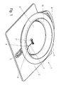
- eine perspektivische Ansicht einer erfindungsgemäßen Halteplatte für einen Filterbeutel;
- Figur 2
- eine Seitenansicht der Halteplatte der
Figur 1 mit Filtermaterial; - Figur 3
- eine perspektivische Ansicht der Halteplatte der
Figur 1 mit geöffneter Verschlussvorrichtung, und - Figur 4
- eine Seitenansicht einer Halteplatte gemäß einer modifizierten Ausführungsform.
- Eine Halteplatte 1 für einen Filterbeutel für einen Staubsauger umfasst ein erstes plattenförmiges Teil 2, das an einer Außenseite eines Filterbeutels angebracht wird, und ein Haltemittel aufweist, um die Halteplatte an einer Halteeinrichtung eines Staubsaugers zu fixieren. Die Haltemittel können beispielsweise als Aussparungen 3, Vorsprünge oder Haken ausgebildet sein, wobei die Halteplatte 1 über einen Griffabschnitt 4 handhabbar ist. An der Halteplatte 1 ist eine Verschlussvorrichtung in Form einer verschwenkbaren Verschlussklappe 5 vorgesehen, die über eine Feder 6 in die geschossene Position vorgespannt ist. Die Feder 6 ist in dem dargestellten Ausführungsbeispiel als Schraubenfeder ausgebildet, die mit einem Schenkel 7 auf einer Innenseite der Verschlussklappe 5 an einer U-förmigen Aufnahme 17 abgestützt ist, um die nach innen öffnende Verschlussklappe 5 in die geschossene Position vorzuspannen. Die Schraubenfeder kann mit einem anderen Schenkel an einem Block 8 fixiert sein, der benachbart zu der Drehachse der Verschlussklappe 5 angeordnet ist. An der Verschlussklappe 5 können auch ein oder mehrere Verstärkungsrippen vorgesehen sein, die sich vorzugsweise im Wesentlichen senkrecht zur Drehachse der Verschlussklappe 5 erstrecken, um die Kräfte durch die Feder 6 oder eines Stutzen eines Staubsaugers besser verteilen zu können.
- Um die Verschlussklappe 5 ist ein in einen Innenraum eines Filterbeutels hervorstehender Kragen 10 ausgebildet, an dem ein radial nach außen hervorstehender Wandabschnitt 11 vorgesehen ist. Der Kragen 10, der Wandabschnitt 11 sowie das plattenförmige Teil 2 der Halteplatte 1 können als Spritzgussteile aus Kunststoff hergestellt sein und besitzen eine glattwandige Oberfläche.
- In
Figur 2 ist die Halteplatte 1 in einer Einbausituation gezeigt, bei der ein Filtermaterial 20, beispielsweise ein mehrlagiges Filtermaterial aus Vliesstoff, an dem plattenförmigen Teil 2 der Halteplatte 1 festgelegt ist. In dem Filtermaterial 20 ist eine Einlassöffnung 21 ausgebildet, innerhalb der der Kragen 10 angeordnet ist. Der plattenförmige Teil 2 ist mit dem Kragen 10 innerhalb der Einlassöffnung 21 verbunden, beispielsweise durch Verkleben oder Verschweißen. - Wie in
Figur 2 gezeigt ist, ist die Höhe h des Kragens 10 so bemessen, dass dieser von einer Innenseite des Filtermaterials 20 in den Innenraum des Filterbeutels hervorsteht. Die Höhe h kann dabei in einem Bereich zwischen 2 mm bis 30 mm, insbesondere 4 mm bis 10 mm, liegen. Etwas unterhalb dem inneren Ende des Kragens ist der radial nach außen hervorstehende Wandabschnitt 11 ausgebildet, der in einem Abstand H von der Innenseite des Filtermaterials 20 angeordnet ist, beispielsweise in einem Bereich zwischen 4 mm und 8 mm, damit in einem Spalt 22 zwischen dem Filtermaterial 20 und dem Wandabschnitt 11 Staub angesammelt werden kann. Dadurch kann das Filtermaterial 20 auch im Bereich unterhalb des radial hervorstehenden Wandabschnittes 11 zur Filterung genutzt werden. Versuche mit der erfindungsgemäßen Halteplatte 1 haben gezeigt, dass trotz der Ausbildung des radialen Wandabschnittes 11 das Filtermaterial 20 an dem Spalt 22 durchströmt wird und zu Filterzwecken genutzt wird, wobei sich bei zunehmender Befüllung des Filterbeutels ein Filterkuchen auch in diesem Spalt 22 ausbildet. - Das Filtermaterial 20 kann dabei über eine ringförmige Naht 23 an dem plattenförmigen Teil 2 der Halteplatte 1 festgelegt sein, die vorzugsweise im Bereich des Spaltes 22 angeordnet ist.
- In
Figur 3 ist die Halteplatte 1 mit einer geöffneten Verschlussklappe 5 gezeigt. In dem plattenförmigen Teil 2 der Halteplatte 1 ist eine Öffnung 13 vorgesehen, die kleiner ausgebildet ist als die Einlassöffnung 21, die von einer ringförmigen elastischen Dichtung 12 umgeben ist. Die Verschlussklappe 5 kann in der geschossenen Position an der elastischen Dichtung 12 zur Anlage kommen. - In
Figur 4 ist eine gegenüber dem vorangegangen Ausführungsbeispiel modifizierte Halteplatte 1' gezeigt, die einen schräg nach außen aufspreizenden Kragen 10' aufweist. Im Übrigen ist die Halteplatte 1' wie das erste Ausführungsbeispiel ausgebildet. Ein Winkel α zwischen einer Ebene der Einströmöffnung in der Halteplatte 1' und dem Kragen10' lieft in einem Bereich zwischen 45° und 90°, insbesondere 70° bis 85°. Eine hervorstehende Kante 15 des Kragens 10' kann dabei einen größeren Durchmesser besitzen als die Öffnung in dem Filtermaterial 20. Dann wird die Halteplatte 1 mit dem plattenförmigen Teil 2 an einer Außenseite des Filtermaterials 20 festgelegt, während das zweite Teil der Halteplatte mit dem Kragen 10' von einer gegenüberliegenden Seite zugeführt wird und dann mit dem ersten plattenförmigen Teil 2 verklebt oder verschweißt wird. - In den gezeigten Ausführungsbeispielen ist lediglich eine Verschlussklappe 5 als Verschlussvorrichtung vorgesehen. Es ist natürlich möglich, auch zwei Verschlussklappen vorzusehen, die eine Öffnung 13 an der Halteplatte 1 öffnen und schließen können.
- Ferner ist in dem gezeigten Ausführungsbeispielen das Filtermaterial 20 an dem plattenförmigen Teil 2 festgelegt, während innerhalb der kreisförmigen Einlassöffnung 21 der Kragen 10 oder 10' an dem plattenförmigen Teil 2 festgelegt ist. Es ist natürlich auch möglich, an einer einzigen ringförmigen Naht den Kragen 10 oder 10' mit dem Filtermaterial 20 sowie dem plattenförmigen Teil 2 zu verbinden, also nur eine Verbindungsstelle vorzusehen.
- In dem gezeigten Ausführungsbeispiel ist der Kragen 10 oder 10' ringförmig mit einem umlaufenden leicht aufspreizenden Wandabschnitt ausgebildet. Es ist natürlich möglich, an dem Kragen 10 Aussparungen vorzusehen, beispielsweise um den Öffnungswinkel der Verschlussklappe 5 zu vergrößern, die dann zur Ebene der Öffnung 13 in dem plattenförmigen Teil 2 in einem Winkel zwischen 85° und 110°, insbesondere über 90°, öffnen kann.
- Statt der Feder 6 in Form einer Schraubenfeder können natürlich auch andere Federn zum Vorspannen der Verschlussklappe 5 in die geschlossene Position vorgesehen werden, beispielswese Blattfedern oder Biegefedern.
- Bei dem Herstellungsverfahren kann zunächst das Filtermaterial 20 mit einem ersten plattenförmigen Teil 2 der Halteplatte1 fixiert werden, insbesondere über eine ringförmige Schweißnaht oder ein Verkleben. In einem zweiten Schritt wird dann das zweite Teil der Halteplatte mit dem Kragen 10 oder 10' mit dem ersten plattenförmigen Teil 2 der Halteplatte 1 verbunden, ebenfalls durch Kleben oder Schweißen. Die Dichtung 12 kann dabei wahlweise mit dem ersten Teil 2 oder dem zweiten Teil der Halteplatte verbunden sein. Es ist auch möglich, den Kragen 10 oder 10' integral mit der Dichtung 12 auszubilden. Anschließend kann dann das Filtermaterial mit der Halteplatte zu einem Filterbeutel konfektioniert werden.
-
- 1, 1'
- Halteplatte
- 2
- plattenförmiges Teil
- 3
- Aussparungen
- 4
- Griffabschnitt
- 5
- Verschlussklappe
- 6
- Feder
- 7
- Schenkel
- 8
- Block
- 10, 10'
- Kragen
- 11
- Wandabschnitt
- 12
- Dichtung
- 13
- Öffnung
- 15
- Kante
- 17
- Aufnahme
- 20
- Filtermaterial
- 21
- Einlassöffnung
- 22
- Spalt
- 23
- Naht
- h
- Höhe
- H
- Abstand
Claims (14)
- Filterbeutel für einen Staubsauger, mit einem Filtermaterial (20), in dem eine Einlassöffnung (21) vorgesehen ist, und einer an der Einlassöffnung angeordneten Halteplatte (1), die an einer Halteeinrichtung eines Staubsaugers zur Halterung des Filterbeutels anbringbar ist, wobei an der Halteplatte (1) eine Verschlussvorrichtung (5) zum Verschließen der Einlassöffnung vorgesehen ist, dadurch gekennzeichnet, dass die Halteplatte (1) zweiteilig ausgebildet ist und die beiden Teile miteinander verklebt oder verschweißt sind und an der Halteplatte (1) mindestens ein in einen Innenraum des Filterbeutels hervorstehender Kragen (10) vorgesehen ist, mittels dem die Ausbildung eines Filterkuchens von dem Filtermaterial (20) zu der Verschlussvorrichtung (5) hin verhindert wird.
- Filterbeutel nach Anspruch 1, dadurch gekennzeichnet, dass der Kragen (10) ringförmig ausgebildet ist.
- Filterbeutel nach Anspruch 1 oder 2, dadurch gekennzeichnet, dass der Kragen (10) die Einlassöffnung (21) in dem Filtermaterial (20) durchgreift und innerhalb des Kragens (10) eine Öffnung (13) in der Halteplatte (1) vorgesehen ist.
- Filterbeutel nach einem der vorhergehenden Ansprüche, dadurch gekennzeichnet, dass das Filtermaterial (20) an der Halteplatte (1) festgelegt ist und das Filtermaterial (20) ringförmig um den Kragen (10) angeordnet ist.
- Filterbeutel nach einem der vorhergehenden Ansprüche, dadurch gekennzeichnet, dass der Kragen (10) nach außen aufspreizend ausgebildet ist.
- Filterbeutel nach einem der vorhergehenden Ansprüche, dadurch gekennzeichnet, dass an dem Kragen (10) ein im Wesentlichen parallel zur Ebene der Einlassöffnung (21) ausgebildeter Wandabschnitt (11) vorgesehen ist.
- Filterbeutel nach Anspruch 6, dadurch gekennzeichnet, dass der Wandabschnitt (11) radial nachaußen von dem Kragen (10) hervorsteht.
- Filterbeutel nach einem der vorhergehenden Ansprüche, dadurch gekennzeichnet, dass die Einlassöffnung (21) in dem Filtermaterial (20) kleiner ausgebildet ist als ein Teil des Kragens (10) oder ein an dem Kragen (10) radial hervorstehender Wandabschnitt (11).
- Filterbeutel nach einem der vorhergehenden Ansprüche, dadurch gekennzeichnet, dass die Höhe des Kragens (10) in einem Bereich zwischen 2 mm und 30 mm, insbesondere 4 mm bis 10 mm, liegt.
- Filterbeutel nach einem der vorhergehenden Ansprüche, dadurch gekennzeichnet, dass an der Halteplatte (1) ein elastischer Dichtring (12) für die Verschlussvorrichtung (5) vorgesehen ist.
- Filterbeutel nach einem der vorhergehenden Ansprüche, dadurch gekennzeichnet, dass die Verschlussvorrichtung (5) eine verschwenkbare Verschlussklappe aufweist.
- Halteplatte (1) für einen Filterbeutel nach einem der vorhergehenden Ansprüche.
- Verfahren zur Herstellung einer Halteplatte für einen Filterbeutel, wobei an der Halteplatte (1) mindestens ein hervorstehender Kragen (10) vorgesehen ist, dadurch gekennzeichnet, dass die Halteplatte (1) zweiteilig ausgebildet ist und die beiden Teile miteinander verklebt oder verschweißt werden.
- Verfahren nach Anspruch 13, dadurch gekennzeichnet, dass zunächst das Filtermaterial an einem ersten plattenförmigen Teil der Halteplatte fixiert wird, und dann in einem zweiten Schritt das zweite Teil der Halteplatte, beispielsweise mit dem Kragen, auf das erste Teil der Halteplatte fixiert wird.
Applications Claiming Priority (1)
| Application Number | Priority Date | Filing Date | Title |
|---|---|---|---|
| DE102013101991.9A DE102013101991A1 (de) | 2013-02-28 | 2013-02-28 | Filterbeutel für einen Staubsauger |
Publications (2)
| Publication Number | Publication Date |
|---|---|
| EP2772173A1 true EP2772173A1 (de) | 2014-09-03 |
| EP2772173B1 EP2772173B1 (de) | 2016-09-21 |
Family
ID=50151108
Family Applications (1)
| Application Number | Title | Priority Date | Filing Date |
|---|---|---|---|
| EP14154787.7A Active EP2772173B1 (de) | 2013-02-28 | 2014-02-12 | Filterbeutel für einen Staubsauger und Verfahren zur Herstellung einer Halteplatte für einen Filterbeutel |
Country Status (2)
| Country | Link |
|---|---|
| EP (1) | EP2772173B1 (de) |
| DE (1) | DE102013101991A1 (de) |
Cited By (10)
| Publication number | Priority date | Publication date | Assignee | Title |
|---|---|---|---|---|
| EP2923624A3 (de) * | 2014-03-25 | 2016-02-17 | Vorwerk & Co. Interholding GmbH | Staubfilterbeutel für einen staubsauger sowie anordnung eines staubfilterbeutels in einem staubsauger |
| USD840615S1 (en) | 2016-10-14 | 2019-02-12 | Tti (Macao Commercial Offshore) Limited | Handheld vacuum cleaner |
| USD844265S1 (en) | 2016-10-14 | 2019-03-26 | Tti (Macao Commercial Offshore) Limited | Handheld vacuum cleaner |
| US10470625B2 (en) | 2016-04-15 | 2019-11-12 | Tti (Macao Commercial Offshore) Limited | Vacuum cleaner and filter for a vacuum cleaner |
| USD911642S1 (en) | 2017-12-05 | 2021-02-23 | Techtronic Floor Care Technology Limited | Housing for a filter |
| EP3821776A1 (de) | 2019-11-12 | 2021-05-19 | Eurofilters Holding N.V. | Staubsaugerfilterbeutel für einen handstaubsauger |
| EP3821777A1 (de) | 2019-11-12 | 2021-05-19 | Eurofilters Holding N.V. | Staubsaugerfilterbeutel für einen handstaubsauger |
| EP3847937B1 (de) | 2020-01-13 | 2022-05-04 | BRANOfilter GmbH | Staubsaugerfilterbeuteleinrichtung |
| US11607637B2 (en) | 2018-08-31 | 2023-03-21 | Milwaukee Electric Tool Corporation | Power tool including an air filter and debris collector |
| EP4133983B1 (de) | 2021-08-13 | 2024-06-26 | Miele & Cie. KG | Staubbeutel |
Families Citing this family (2)
| Publication number | Priority date | Publication date | Assignee | Title |
|---|---|---|---|---|
| CN111067418A (zh) | 2018-10-19 | 2020-04-28 | 德国福维克控股公司 | 滤尘袋 |
| DE102022130755A1 (de) | 2022-11-21 | 2024-05-23 | Wolf Pvg Gmbh & Co. Kommanditgesellschaft | Haltevorrichtung zur Halterung eines Staubsaugerbeutels und Verfahren zur Herstellung einer Haltevorrichtung |
Citations (5)
| Publication number | Priority date | Publication date | Assignee | Title |
|---|---|---|---|---|
| DE102005045548A1 (de) * | 2005-09-23 | 2007-03-29 | Vorwerk & Co. Interholding Gmbh | Anordnung eines Filterbeutels in einem Elektrostaubsauger sowie Elektrostaubsauger mit einem Stutzen |
| WO2009024217A1 (de) | 2007-08-17 | 2009-02-26 | Eurofilters Holding N.V. | Staubsaugerfilterbeutel |
| DE102008046200A1 (de) | 2007-09-28 | 2009-04-02 | Vorwerk & Co. Interholding Gmbh | Filterbeutel für einen Staubsauger |
| DE202010015038U1 (de) * | 2009-11-27 | 2011-01-27 | Haider, Wolfgang | Staubbehälter für Staubsauger |
| DE202008018054U1 (de) * | 2008-08-29 | 2011-04-28 | Vorwerk & Co. Interholding Gmbh | Filterbeutel für einen Staubsauger |
Family Cites Families (4)
| Publication number | Priority date | Publication date | Assignee | Title |
|---|---|---|---|---|
| DE102007053151B4 (de) * | 2007-11-08 | 2025-05-08 | Wolf Pvg Gmbh & Co. Kommanditgesellschaft | Halteplatte für einen Staubsaugerbeutel und Verfahren zu deren Herstellung |
| DE102010060175A1 (de) * | 2010-09-06 | 2012-03-08 | Vorwerk & Co. Interholding Gmbh | Staubfilterbeutel |
| DE102010038113A1 (de) * | 2010-10-12 | 2011-03-03 | Vorwerk & Co. Interholding Gmbh | Staubfilterbeutel-Aufnahmekammer eines Staubsaugers |
| DE102010060353A1 (de) * | 2010-11-04 | 2012-05-10 | Papierverarbeitung Görlitz GmbH | Staubfilterbeutel für Staubsauger |
-
2013
- 2013-02-28 DE DE102013101991.9A patent/DE102013101991A1/de not_active Withdrawn
-
2014
- 2014-02-12 EP EP14154787.7A patent/EP2772173B1/de active Active
Patent Citations (5)
| Publication number | Priority date | Publication date | Assignee | Title |
|---|---|---|---|---|
| DE102005045548A1 (de) * | 2005-09-23 | 2007-03-29 | Vorwerk & Co. Interholding Gmbh | Anordnung eines Filterbeutels in einem Elektrostaubsauger sowie Elektrostaubsauger mit einem Stutzen |
| WO2009024217A1 (de) | 2007-08-17 | 2009-02-26 | Eurofilters Holding N.V. | Staubsaugerfilterbeutel |
| DE102008046200A1 (de) | 2007-09-28 | 2009-04-02 | Vorwerk & Co. Interholding Gmbh | Filterbeutel für einen Staubsauger |
| DE202008018054U1 (de) * | 2008-08-29 | 2011-04-28 | Vorwerk & Co. Interholding Gmbh | Filterbeutel für einen Staubsauger |
| DE202010015038U1 (de) * | 2009-11-27 | 2011-01-27 | Haider, Wolfgang | Staubbehälter für Staubsauger |
Cited By (15)
| Publication number | Priority date | Publication date | Assignee | Title |
|---|---|---|---|---|
| EP2923624A3 (de) * | 2014-03-25 | 2016-02-17 | Vorwerk & Co. Interholding GmbH | Staubfilterbeutel für einen staubsauger sowie anordnung eines staubfilterbeutels in einem staubsauger |
| US11363922B2 (en) | 2016-04-15 | 2022-06-21 | Techtronic Floor Care Technology Limited | Vacuum cleaner and filter for a vacuum cleaner |
| US10470625B2 (en) | 2016-04-15 | 2019-11-12 | Tti (Macao Commercial Offshore) Limited | Vacuum cleaner and filter for a vacuum cleaner |
| US10531772B2 (en) | 2016-04-15 | 2020-01-14 | Tti (Macao Commercial Offshore) Limited | Handheld vacuum cleaner |
| US10743731B2 (en) | 2016-04-15 | 2020-08-18 | Tti (Macao Commercial Offshore) Limited | Vacuum filter |
| USD840615S1 (en) | 2016-10-14 | 2019-02-12 | Tti (Macao Commercial Offshore) Limited | Handheld vacuum cleaner |
| USD844265S1 (en) | 2016-10-14 | 2019-03-26 | Tti (Macao Commercial Offshore) Limited | Handheld vacuum cleaner |
| USD911642S1 (en) | 2017-12-05 | 2021-02-23 | Techtronic Floor Care Technology Limited | Housing for a filter |
| US11607637B2 (en) | 2018-08-31 | 2023-03-21 | Milwaukee Electric Tool Corporation | Power tool including an air filter and debris collector |
| EP3821777A1 (de) | 2019-11-12 | 2021-05-19 | Eurofilters Holding N.V. | Staubsaugerfilterbeutel für einen handstaubsauger |
| EP3821776A1 (de) | 2019-11-12 | 2021-05-19 | Eurofilters Holding N.V. | Staubsaugerfilterbeutel für einen handstaubsauger |
| EP3821776B1 (de) * | 2019-11-12 | 2025-01-01 | Eurofilters Holding N.V. | Staubsaugerfilterbeutel für einen handstaubsauger |
| EP3821777B1 (de) * | 2019-11-12 | 2025-01-01 | Eurofilters Holding N.V. | Staubsaugerfilterbeutel für einen handstaubsauger |
| EP3847937B1 (de) | 2020-01-13 | 2022-05-04 | BRANOfilter GmbH | Staubsaugerfilterbeuteleinrichtung |
| EP4133983B1 (de) | 2021-08-13 | 2024-06-26 | Miele & Cie. KG | Staubbeutel |
Also Published As
| Publication number | Publication date |
|---|---|
| DE102013101991A1 (de) | 2014-08-28 |
| EP2772173B1 (de) | 2016-09-21 |
Similar Documents
| Publication | Publication Date | Title |
|---|---|---|
| EP2772173B1 (de) | Filterbeutel für einen Staubsauger und Verfahren zur Herstellung einer Halteplatte für einen Filterbeutel | |
| EP1992395B1 (de) | Filter, insbesondere Luftfilter | |
| EP2051892B1 (de) | Druckluftversorgungseinrichtung für ein nutzfahrzeug und lufttrocknerpatrone | |
| EP2051891B1 (de) | Druckluftversorgungseinrichtung | |
| EP2029258B1 (de) | Kompaktfilterelement mit ausklopfschutz | |
| DE102009060517A1 (de) | Filtereinrichtung für Brennkraftmaschinen | |
| EP2509699B1 (de) | Filterelement und luftfilter | |
| DE102011106503A1 (de) | Luftfilterelement, Filtergehäuse und Filteranordnung | |
| DE202013103508U1 (de) | Staubsaugerbeutel | |
| EP2772172B1 (de) | Halteplatte und Verfahren zur Herstellung einer Halteplatte | |
| EP3958996A1 (de) | Filtervorrichtung | |
| WO2011127920A1 (de) | Kraftstofffilter mit vor- und hauptfilter | |
| EP3066968B1 (de) | Staubfilterbeutel mit halteplatte | |
| WO2013023828A1 (de) | Ansatzstutzen für filterschläuche | |
| DE202012000417U1 (de) | Filter und Filterkartusche, die eine außermittige Entleerung zulassen | |
| DE29921543U1 (de) | Filtereinsatz für einen Flüssigkeitsfilter | |
| DE202004008972U1 (de) | Staubfilterbeutel | |
| DE9405390U1 (de) | Filteranordnung zum Filtern einer Fluidströmung | |
| WO1997048609A1 (de) | Karton-rohrabschluss, sowie dose und dosendeckel damit | |
| DE202008016299U1 (de) | Halteplatte | |
| EP3219236B1 (de) | Halteplatte mit verbessertem verschluss | |
| EP3219237B1 (de) | Halteplatte mit verbessertem verschlusselement | |
| DE202009015439U1 (de) | Ausgießeinsatz und Verschluss für einen Behälter | |
| DE102022130755A1 (de) | Haltevorrichtung zur Halterung eines Staubsaugerbeutels und Verfahren zur Herstellung einer Haltevorrichtung | |
| WO2016058778A1 (de) | Filterelement, insbesondere zur gasfiltration |
Legal Events
| Date | Code | Title | Description |
|---|---|---|---|
| PUAI | Public reference made under article 153(3) epc to a published international application that has entered the european phase |
Free format text: ORIGINAL CODE: 0009012 |
|
| 17P | Request for examination filed |
Effective date: 20140514 |
|
| AK | Designated contracting states |
Kind code of ref document: A1 Designated state(s): AL AT BE BG CH CY CZ DE DK EE ES FI FR GB GR HR HU IE IS IT LI LT LU LV MC MK MT NL NO PL PT RO RS SE SI SK SM TR |
|
| AX | Request for extension of the european patent |
Extension state: BA ME |
|
| GRAP | Despatch of communication of intention to grant a patent |
Free format text: ORIGINAL CODE: EPIDOSNIGR1 |
|
| RIC1 | Information provided on ipc code assigned before grant |
Ipc: A47L 9/14 20060101AFI20160513BHEP |
|
| INTG | Intention to grant announced |
Effective date: 20160608 |
|
| GRAS | Grant fee paid |
Free format text: ORIGINAL CODE: EPIDOSNIGR3 |
|
| GRAA | (expected) grant |
Free format text: ORIGINAL CODE: 0009210 |
|
| AK | Designated contracting states |
Kind code of ref document: B1 Designated state(s): AL AT BE BG CH CY CZ DE DK EE ES FI FR GB GR HR HU IE IS IT LI LT LU LV MC MK MT NL NO PL PT RO RS SE SI SK SM TR |
|
| REG | Reference to a national code |
Ref country code: GB Ref legal event code: FG4D Free format text: NOT ENGLISH |
|
| REG | Reference to a national code |
Ref country code: CH Ref legal event code: EP |
|
| REG | Reference to a national code |
Ref country code: AT Ref legal event code: REF Ref document number: 830358 Country of ref document: AT Kind code of ref document: T Effective date: 20161015 |
|
| REG | Reference to a national code |
Ref country code: IE Ref legal event code: FG4D Free format text: LANGUAGE OF EP DOCUMENT: GERMAN |
|
| REG | Reference to a national code |
Ref country code: DE Ref legal event code: R096 Ref document number: 502014001483 Country of ref document: DE |
|
| REG | Reference to a national code |
Ref country code: LT Ref legal event code: MG4D Ref country code: NL Ref legal event code: MP Effective date: 20160921 |
|
| PG25 | Lapsed in a contracting state [announced via postgrant information from national office to epo] |
Ref country code: LT Free format text: LAPSE BECAUSE OF FAILURE TO SUBMIT A TRANSLATION OF THE DESCRIPTION OR TO PAY THE FEE WITHIN THE PRESCRIBED TIME-LIMIT Effective date: 20160921 Ref country code: FI Free format text: LAPSE BECAUSE OF FAILURE TO SUBMIT A TRANSLATION OF THE DESCRIPTION OR TO PAY THE FEE WITHIN THE PRESCRIBED TIME-LIMIT Effective date: 20160921 Ref country code: RS Free format text: LAPSE BECAUSE OF FAILURE TO SUBMIT A TRANSLATION OF THE DESCRIPTION OR TO PAY THE FEE WITHIN THE PRESCRIBED TIME-LIMIT Effective date: 20160921 Ref country code: NO Free format text: LAPSE BECAUSE OF FAILURE TO SUBMIT A TRANSLATION OF THE DESCRIPTION OR TO PAY THE FEE WITHIN THE PRESCRIBED TIME-LIMIT Effective date: 20161221 |
|
| PG25 | Lapsed in a contracting state [announced via postgrant information from national office to epo] |
Ref country code: NL Free format text: LAPSE BECAUSE OF FAILURE TO SUBMIT A TRANSLATION OF THE DESCRIPTION OR TO PAY THE FEE WITHIN THE PRESCRIBED TIME-LIMIT Effective date: 20160921 Ref country code: LV Free format text: LAPSE BECAUSE OF FAILURE TO SUBMIT A TRANSLATION OF THE DESCRIPTION OR TO PAY THE FEE WITHIN THE PRESCRIBED TIME-LIMIT Effective date: 20160921 Ref country code: SE Free format text: LAPSE BECAUSE OF FAILURE TO SUBMIT A TRANSLATION OF THE DESCRIPTION OR TO PAY THE FEE WITHIN THE PRESCRIBED TIME-LIMIT Effective date: 20160921 Ref country code: GR Free format text: LAPSE BECAUSE OF FAILURE TO SUBMIT A TRANSLATION OF THE DESCRIPTION OR TO PAY THE FEE WITHIN THE PRESCRIBED TIME-LIMIT Effective date: 20161222 |
|
| PG25 | Lapsed in a contracting state [announced via postgrant information from national office to epo] |
Ref country code: RO Free format text: LAPSE BECAUSE OF FAILURE TO SUBMIT A TRANSLATION OF THE DESCRIPTION OR TO PAY THE FEE WITHIN THE PRESCRIBED TIME-LIMIT Effective date: 20160921 Ref country code: EE Free format text: LAPSE BECAUSE OF FAILURE TO SUBMIT A TRANSLATION OF THE DESCRIPTION OR TO PAY THE FEE WITHIN THE PRESCRIBED TIME-LIMIT Effective date: 20160921 |
|
| PG25 | Lapsed in a contracting state [announced via postgrant information from national office to epo] |
Ref country code: SM Free format text: LAPSE BECAUSE OF FAILURE TO SUBMIT A TRANSLATION OF THE DESCRIPTION OR TO PAY THE FEE WITHIN THE PRESCRIBED TIME-LIMIT Effective date: 20160921 Ref country code: BE Free format text: LAPSE BECAUSE OF NON-PAYMENT OF DUE FEES Effective date: 20170228 Ref country code: PL Free format text: LAPSE BECAUSE OF FAILURE TO SUBMIT A TRANSLATION OF THE DESCRIPTION OR TO PAY THE FEE WITHIN THE PRESCRIBED TIME-LIMIT Effective date: 20160921 Ref country code: CZ Free format text: LAPSE BECAUSE OF FAILURE TO SUBMIT A TRANSLATION OF THE DESCRIPTION OR TO PAY THE FEE WITHIN THE PRESCRIBED TIME-LIMIT Effective date: 20160921 Ref country code: BG Free format text: LAPSE BECAUSE OF FAILURE TO SUBMIT A TRANSLATION OF THE DESCRIPTION OR TO PAY THE FEE WITHIN THE PRESCRIBED TIME-LIMIT Effective date: 20161221 Ref country code: ES Free format text: LAPSE BECAUSE OF FAILURE TO SUBMIT A TRANSLATION OF THE DESCRIPTION OR TO PAY THE FEE WITHIN THE PRESCRIBED TIME-LIMIT Effective date: 20160921 Ref country code: IS Free format text: LAPSE BECAUSE OF FAILURE TO SUBMIT A TRANSLATION OF THE DESCRIPTION OR TO PAY THE FEE WITHIN THE PRESCRIBED TIME-LIMIT Effective date: 20170121 Ref country code: PT Free format text: LAPSE BECAUSE OF FAILURE TO SUBMIT A TRANSLATION OF THE DESCRIPTION OR TO PAY THE FEE WITHIN THE PRESCRIBED TIME-LIMIT Effective date: 20170123 Ref country code: SK Free format text: LAPSE BECAUSE OF FAILURE TO SUBMIT A TRANSLATION OF THE DESCRIPTION OR TO PAY THE FEE WITHIN THE PRESCRIBED TIME-LIMIT Effective date: 20160921 |
|
| REG | Reference to a national code |
Ref country code: DE Ref legal event code: R097 Ref document number: 502014001483 Country of ref document: DE |
|
| PG25 | Lapsed in a contracting state [announced via postgrant information from national office to epo] |
Ref country code: IT Free format text: LAPSE BECAUSE OF FAILURE TO SUBMIT A TRANSLATION OF THE DESCRIPTION OR TO PAY THE FEE WITHIN THE PRESCRIBED TIME-LIMIT Effective date: 20160921 |
|
| PLBE | No opposition filed within time limit |
Free format text: ORIGINAL CODE: 0009261 |
|
| STAA | Information on the status of an ep patent application or granted ep patent |
Free format text: STATUS: NO OPPOSITION FILED WITHIN TIME LIMIT |
|
| PG25 | Lapsed in a contracting state [announced via postgrant information from national office to epo] |
Ref country code: DK Free format text: LAPSE BECAUSE OF FAILURE TO SUBMIT A TRANSLATION OF THE DESCRIPTION OR TO PAY THE FEE WITHIN THE PRESCRIBED TIME-LIMIT Effective date: 20160921 |
|
| 26N | No opposition filed |
Effective date: 20170622 |
|
| PG25 | Lapsed in a contracting state [announced via postgrant information from national office to epo] |
Ref country code: MC Free format text: LAPSE BECAUSE OF FAILURE TO SUBMIT A TRANSLATION OF THE DESCRIPTION OR TO PAY THE FEE WITHIN THE PRESCRIBED TIME-LIMIT Effective date: 20160921 |
|
| REG | Reference to a national code |
Ref country code: CH Ref legal event code: PL |
|
| PG25 | Lapsed in a contracting state [announced via postgrant information from national office to epo] |
Ref country code: LI Free format text: LAPSE BECAUSE OF NON-PAYMENT OF DUE FEES Effective date: 20170228 Ref country code: CH Free format text: LAPSE BECAUSE OF NON-PAYMENT OF DUE FEES Effective date: 20170228 |
|
| REG | Reference to a national code |
Ref country code: IE Ref legal event code: MM4A |
|
| PG25 | Lapsed in a contracting state [announced via postgrant information from national office to epo] |
Ref country code: SI Free format text: LAPSE BECAUSE OF FAILURE TO SUBMIT A TRANSLATION OF THE DESCRIPTION OR TO PAY THE FEE WITHIN THE PRESCRIBED TIME-LIMIT Effective date: 20160921 |
|
| REG | Reference to a national code |
Ref country code: FR Ref legal event code: ST Effective date: 20171031 |
|
| PG25 | Lapsed in a contracting state [announced via postgrant information from national office to epo] |
Ref country code: LU Free format text: LAPSE BECAUSE OF NON-PAYMENT OF DUE FEES Effective date: 20170212 |
|
| PG25 | Lapsed in a contracting state [announced via postgrant information from national office to epo] |
Ref country code: FR Free format text: LAPSE BECAUSE OF NON-PAYMENT OF DUE FEES Effective date: 20170228 |
|
| REG | Reference to a national code |
Ref country code: BE Ref legal event code: MM Effective date: 20170228 |
|
| PG25 | Lapsed in a contracting state [announced via postgrant information from national office to epo] |
Ref country code: IE Free format text: LAPSE BECAUSE OF NON-PAYMENT OF DUE FEES Effective date: 20170212 |
|
| PG25 | Lapsed in a contracting state [announced via postgrant information from national office to epo] |
Ref country code: MT Free format text: LAPSE BECAUSE OF FAILURE TO SUBMIT A TRANSLATION OF THE DESCRIPTION OR TO PAY THE FEE WITHIN THE PRESCRIBED TIME-LIMIT Effective date: 20160921 |
|
| GBPC | Gb: european patent ceased through non-payment of renewal fee |
Effective date: 20180212 |
|
| PG25 | Lapsed in a contracting state [announced via postgrant information from national office to epo] |
Ref country code: AL Free format text: LAPSE BECAUSE OF FAILURE TO SUBMIT A TRANSLATION OF THE DESCRIPTION OR TO PAY THE FEE WITHIN THE PRESCRIBED TIME-LIMIT Effective date: 20160921 |
|
| PG25 | Lapsed in a contracting state [announced via postgrant information from national office to epo] |
Ref country code: GB Free format text: LAPSE BECAUSE OF NON-PAYMENT OF DUE FEES Effective date: 20180212 |
|
| PG25 | Lapsed in a contracting state [announced via postgrant information from national office to epo] |
Ref country code: HU Free format text: LAPSE BECAUSE OF FAILURE TO SUBMIT A TRANSLATION OF THE DESCRIPTION OR TO PAY THE FEE WITHIN THE PRESCRIBED TIME-LIMIT; INVALID AB INITIO Effective date: 20140212 |
|
| PG25 | Lapsed in a contracting state [announced via postgrant information from national office to epo] |
Ref country code: CY Free format text: LAPSE BECAUSE OF NON-PAYMENT OF DUE FEES Effective date: 20160921 |
|
| PG25 | Lapsed in a contracting state [announced via postgrant information from national office to epo] |
Ref country code: MK Free format text: LAPSE BECAUSE OF FAILURE TO SUBMIT A TRANSLATION OF THE DESCRIPTION OR TO PAY THE FEE WITHIN THE PRESCRIBED TIME-LIMIT Effective date: 20160921 |
|
| PG25 | Lapsed in a contracting state [announced via postgrant information from national office to epo] |
Ref country code: TR Free format text: LAPSE BECAUSE OF FAILURE TO SUBMIT A TRANSLATION OF THE DESCRIPTION OR TO PAY THE FEE WITHIN THE PRESCRIBED TIME-LIMIT Effective date: 20160921 |
|
| REG | Reference to a national code |
Ref country code: AT Ref legal event code: MM01 Ref document number: 830358 Country of ref document: AT Kind code of ref document: T Effective date: 20190212 |
|
| PG25 | Lapsed in a contracting state [announced via postgrant information from national office to epo] |
Ref country code: AT Free format text: LAPSE BECAUSE OF NON-PAYMENT OF DUE FEES Effective date: 20190212 |
|
| PG25 | Lapsed in a contracting state [announced via postgrant information from national office to epo] |
Ref country code: HR Free format text: LAPSE BECAUSE OF FAILURE TO SUBMIT A TRANSLATION OF THE DESCRIPTION OR TO PAY THE FEE WITHIN THE PRESCRIBED TIME-LIMIT Effective date: 20160921 |
|
| REG | Reference to a national code |
Ref country code: DE Ref legal event code: R039 Ref document number: 502014001483 Country of ref document: DE Ref country code: DE Ref legal event code: R008 Ref document number: 502014001483 Country of ref document: DE |
|
| PGFP | Annual fee paid to national office [announced via postgrant information from national office to epo] |
Ref country code: DE Payment date: 20250228 Year of fee payment: 12 |