EP2771200B2 - Vent valve - Google Patents
Vent valve Download PDFInfo
- Publication number
- EP2771200B2 EP2771200B2 EP12765999.3A EP12765999A EP2771200B2 EP 2771200 B2 EP2771200 B2 EP 2771200B2 EP 12765999 A EP12765999 A EP 12765999A EP 2771200 B2 EP2771200 B2 EP 2771200B2
- Authority
- EP
- European Patent Office
- Prior art keywords
- valve
- valve element
- vent
- relief opening
- vent valve
- Prior art date
- Legal status (The legal status is an assumption and is not a legal conclusion. Google has not performed a legal analysis and makes no representation as to the accuracy of the status listed.)
- Active
Links
- 239000002828 fuel tank Substances 0.000 claims description 33
- 239000000446 fuel Substances 0.000 claims description 17
- 230000005484 gravity Effects 0.000 claims description 4
- 238000007789 sealing Methods 0.000 description 7
- 238000013022 venting Methods 0.000 description 7
- 239000007788 liquid Substances 0.000 description 4
- 239000004952 Polyamide Substances 0.000 description 2
- 230000001419 dependent effect Effects 0.000 description 2
- 239000000945 filler Substances 0.000 description 2
- 239000012530 fluid Substances 0.000 description 2
- 238000000034 method Methods 0.000 description 2
- 229920002647 polyamide Polymers 0.000 description 2
- 230000001133 acceleration Effects 0.000 description 1
- 230000009849 deactivation Effects 0.000 description 1
- 230000000694 effects Effects 0.000 description 1
- 238000005429 filling process Methods 0.000 description 1
- 238000009434 installation Methods 0.000 description 1
- 238000004519 manufacturing process Methods 0.000 description 1
- 238000010943 off-gassing Methods 0.000 description 1
- 230000002085 persistent effect Effects 0.000 description 1
- 238000005096 rolling process Methods 0.000 description 1
- 229920001169 thermoplastic Polymers 0.000 description 1
- 239000004416 thermosoftening plastic Substances 0.000 description 1
Images


Classifications
-
- B—PERFORMING OPERATIONS; TRANSPORTING
- B60—VEHICLES IN GENERAL
- B60K—ARRANGEMENT OR MOUNTING OF PROPULSION UNITS OR OF TRANSMISSIONS IN VEHICLES; ARRANGEMENT OR MOUNTING OF PLURAL DIVERSE PRIME-MOVERS IN VEHICLES; AUXILIARY DRIVES FOR VEHICLES; INSTRUMENTATION OR DASHBOARDS FOR VEHICLES; ARRANGEMENTS IN CONNECTION WITH COOLING, AIR INTAKE, GAS EXHAUST OR FUEL SUPPLY OF PROPULSION UNITS IN VEHICLES
- B60K15/00—Arrangement in connection with fuel supply of combustion engines or other fuel consuming energy converters, e.g. fuel cells; Mounting or construction of fuel tanks
- B60K15/03—Fuel tanks
- B60K15/035—Fuel tanks characterised by venting means
- B60K15/03504—Fuel tanks characterised by venting means adapted to avoid loss of fuel or fuel vapour, e.g. with vapour recovery systems
-
- B—PERFORMING OPERATIONS; TRANSPORTING
- B60—VEHICLES IN GENERAL
- B60K—ARRANGEMENT OR MOUNTING OF PROPULSION UNITS OR OF TRANSMISSIONS IN VEHICLES; ARRANGEMENT OR MOUNTING OF PLURAL DIVERSE PRIME-MOVERS IN VEHICLES; AUXILIARY DRIVES FOR VEHICLES; INSTRUMENTATION OR DASHBOARDS FOR VEHICLES; ARRANGEMENTS IN CONNECTION WITH COOLING, AIR INTAKE, GAS EXHAUST OR FUEL SUPPLY OF PROPULSION UNITS IN VEHICLES
- B60K15/00—Arrangement in connection with fuel supply of combustion engines or other fuel consuming energy converters, e.g. fuel cells; Mounting or construction of fuel tanks
- B60K15/03—Fuel tanks
- B60K15/035—Fuel tanks characterised by venting means
- B60K15/03519—Valve arrangements in the vent line
-
- F—MECHANICAL ENGINEERING; LIGHTING; HEATING; WEAPONS; BLASTING
- F16—ENGINEERING ELEMENTS AND UNITS; GENERAL MEASURES FOR PRODUCING AND MAINTAINING EFFECTIVE FUNCTIONING OF MACHINES OR INSTALLATIONS; THERMAL INSULATION IN GENERAL
- F16K—VALVES; TAPS; COCKS; ACTUATING-FLOATS; DEVICES FOR VENTING OR AERATING
- F16K17/00—Safety valves; Equalising valves, e.g. pressure relief valves
- F16K17/02—Safety valves; Equalising valves, e.g. pressure relief valves opening on surplus pressure on one side; closing on insufficient pressure on one side
- F16K17/04—Safety valves; Equalising valves, e.g. pressure relief valves opening on surplus pressure on one side; closing on insufficient pressure on one side spring-loaded
-
- F—MECHANICAL ENGINEERING; LIGHTING; HEATING; WEAPONS; BLASTING
- F16—ENGINEERING ELEMENTS AND UNITS; GENERAL MEASURES FOR PRODUCING AND MAINTAINING EFFECTIVE FUNCTIONING OF MACHINES OR INSTALLATIONS; THERMAL INSULATION IN GENERAL
- F16K—VALVES; TAPS; COCKS; ACTUATING-FLOATS; DEVICES FOR VENTING OR AERATING
- F16K17/00—Safety valves; Equalising valves, e.g. pressure relief valves
- F16K17/02—Safety valves; Equalising valves, e.g. pressure relief valves opening on surplus pressure on one side; closing on insufficient pressure on one side
- F16K17/12—Safety valves; Equalising valves, e.g. pressure relief valves opening on surplus pressure on one side; closing on insufficient pressure on one side weight-loaded
-
- F—MECHANICAL ENGINEERING; LIGHTING; HEATING; WEAPONS; BLASTING
- F16—ENGINEERING ELEMENTS AND UNITS; GENERAL MEASURES FOR PRODUCING AND MAINTAINING EFFECTIVE FUNCTIONING OF MACHINES OR INSTALLATIONS; THERMAL INSULATION IN GENERAL
- F16K—VALVES; TAPS; COCKS; ACTUATING-FLOATS; DEVICES FOR VENTING OR AERATING
- F16K24/00—Devices, e.g. valves, for venting or aerating enclosures
- F16K24/04—Devices, e.g. valves, for venting or aerating enclosures for venting only
-
- B—PERFORMING OPERATIONS; TRANSPORTING
- B60—VEHICLES IN GENERAL
- B60K—ARRANGEMENT OR MOUNTING OF PROPULSION UNITS OR OF TRANSMISSIONS IN VEHICLES; ARRANGEMENT OR MOUNTING OF PLURAL DIVERSE PRIME-MOVERS IN VEHICLES; AUXILIARY DRIVES FOR VEHICLES; INSTRUMENTATION OR DASHBOARDS FOR VEHICLES; ARRANGEMENTS IN CONNECTION WITH COOLING, AIR INTAKE, GAS EXHAUST OR FUEL SUPPLY OF PROPULSION UNITS IN VEHICLES
- B60K15/00—Arrangement in connection with fuel supply of combustion engines or other fuel consuming energy converters, e.g. fuel cells; Mounting or construction of fuel tanks
- B60K15/03—Fuel tanks
- B60K2015/03256—Fuel tanks characterised by special valves, the mounting thereof
- B60K2015/03263—Ball valves
-
- B—PERFORMING OPERATIONS; TRANSPORTING
- B60—VEHICLES IN GENERAL
- B60K—ARRANGEMENT OR MOUNTING OF PROPULSION UNITS OR OF TRANSMISSIONS IN VEHICLES; ARRANGEMENT OR MOUNTING OF PLURAL DIVERSE PRIME-MOVERS IN VEHICLES; AUXILIARY DRIVES FOR VEHICLES; INSTRUMENTATION OR DASHBOARDS FOR VEHICLES; ARRANGEMENTS IN CONNECTION WITH COOLING, AIR INTAKE, GAS EXHAUST OR FUEL SUPPLY OF PROPULSION UNITS IN VEHICLES
- B60K15/00—Arrangement in connection with fuel supply of combustion engines or other fuel consuming energy converters, e.g. fuel cells; Mounting or construction of fuel tanks
- B60K15/03—Fuel tanks
- B60K2015/03256—Fuel tanks characterised by special valves, the mounting thereof
- B60K2015/03296—Pressure regulating valves
-
- B—PERFORMING OPERATIONS; TRANSPORTING
- B60—VEHICLES IN GENERAL
- B60K—ARRANGEMENT OR MOUNTING OF PROPULSION UNITS OR OF TRANSMISSIONS IN VEHICLES; ARRANGEMENT OR MOUNTING OF PLURAL DIVERSE PRIME-MOVERS IN VEHICLES; AUXILIARY DRIVES FOR VEHICLES; INSTRUMENTATION OR DASHBOARDS FOR VEHICLES; ARRANGEMENTS IN CONNECTION WITH COOLING, AIR INTAKE, GAS EXHAUST OR FUEL SUPPLY OF PROPULSION UNITS IN VEHICLES
- B60K15/00—Arrangement in connection with fuel supply of combustion engines or other fuel consuming energy converters, e.g. fuel cells; Mounting or construction of fuel tanks
- B60K15/03—Fuel tanks
- B60K2015/03328—Arrangements or special measures related to fuel tanks or fuel handling
- B60K2015/03388—Arrangements or special measures related to fuel tanks or fuel handling in case of a roll over of the vehicle
Description
- The invention relates to a vent valve for controlling the internal tank pressure of a fuel tank, having a valve housing having at least one first connection to the fuel tank and at least one second connection, which can be connected to a vent line leading to a fuel vapour filter, having at least one valve element, which is held in a valve seat in a position in which it closes the first connection by the force of gravity and/or by spring loading and, after a given pressure threshold is exceeded, is raised from the valve seat and, when a given pressure threshold is undershot, returns to the initial position, wherein the valve element is arranged so that it can move within a valve element guide.
- Vent valves of this kind are also referred to as pressure holding valves or as vent valves with a pressure holding function. Particularly in the case where the fuel tank is being refilled, they ensure that the fuel pump nozzle switches off when the predetermined fuel level in the tank is reached. In all non-refuelling states of the motor vehicle, vent valves should allow venting of the tank to a virtually unpressurized state. This means that a very small differential pressure with respect to atmosphere should be possible in the fuel tank, both in the case of processes associated with driving dynamics and also in the case of large pressure fluctuations.
- A vent valve of the type described above is designed either as a separate pressure holding valve or is integrated into a service vent valve of a venting system of a fuel tank.
- The pressure holding function of or pressure control by the vent valve serves primarily to prevent overfilling. During the refilling of a motor vehicle fuel tank, the liquid level within the fuel tank continues to rise until it closes a refill vent valve, e.g. raises a float in the refill vent valve, which closes the relevant venting path. In order to prevent continued filling of the fuel tank beyond the filling level envisaged by the manufacturer, the pressure within the tank must be able to rise within certain limits when the refill vent valve responds, causing the liquid column within the filler pipe of the fuel tank to rise until it closes a snifter hole in the fuel pump nozzle. This results in immediate deactivation of the fuel pump nozzle.
- The maximum fuel level in the fuel tank permitted when refilling is predetermined structurally in such a way that a compensating volume remains in the fuel tank. This compensating volume allows the fuel to expand in the tank due to the effects of temperature and ensures that the venting system of the fuel tank is not wetted by liquid fuel. Maintaining this compensating volume is indispensable for the reliability of operation of the venting system of a fuel tank. The fuel tank must therefore be designed in such a way that intentional overfilling by the user is as far as possible excluded. Such overfilling is also referred to as trickle filling. In general, this is achieved, after the filler pump nozzle has switched off during the filling process, by the user operating the fuel pump nozzle several times in succession at brief intervals in such a way that some of the compensating volume of the fuel tank is nevertheless filled. This is not necessarily problematic, particularly in the case of fuel tanks in which the compensating/outgassing volume of the tank is generously dimensioned.
- In the case of modern passenger vehicles, however, there is an increasing requirement for design and arrangement of the individual components in a manner which is as far as possible optimized in terms of installation space. It is therefore desirable to dimension the compensating volume in the fuel tank so that it is as small as possible. For this purpose, however, it is necessary to improve the venting system of the fuel tank in respect of overfill protection.
- A valve according to the preamble of
claim 1 is for example disclosed inUS 5,253,668 . The valve comprises a smooth-opening, low-hysteresis, pressure-operated ball head valve connected between a fuel tank and a vapour trap in a vehicle system for providing smooth, two-stage, low-hysteresis vapour flow. The valve element is positioned within a cylindrical retainer in the valve body, and the dimensions of the various valve orifices and the geometry of the retainer are determined in view of a specified lift off pressure and ball weight to achieve these flow characteristics. -
US 2003/0094204 A1 discloses a pressure release valve including a housing having a passage formed therein for connection with a fluid source and a seal surface positioned about an opening in the passage. A valve member positioned within the housing is moveable along an axis within the cavity to selectively engage the seal surface in a sealing relationship. The valve member has one or more through holes formed through the valve member which permit fluid to flow through the valve member when the pressure release valve is open. - It is therefore the underlying object of the invention to improve a vent valve of the type stated at the outset in respect of fill protection for a fuel tank.
- The object underlying the invention is achieved by the features of
claim 1, advantageous embodiments are covered by the dependent claims. - The invention is based on the realization that possible trickle filling during the refilling of a fuel tank is achieved by the user exploiting the switching hysteresis of the pressure holding valve during refilling.
- Pressure holding valves of the type described above respond approximately at an excess pressure of 30 mbar within the fuel tank, that is to say they allow a pressure rise up to 30 mbar. If the vent valve responds during the refilling process, the valve element will not instantaneously re-close the inflow opening into the valve housing, and therefore closure of the system will take place only at a pressure significantly below the response pressure. Depending on the design of the valve, the switching hysteresis of the vent valve may be more than 10 mbar, and addition of extra fuel to the compensating volume of the tank is therefore possible in the intervening period, given repeated and persistent operation of the fuel pump nozzle.
- In particular, the invention is based on the realization that more effective overfill protection is ensured particularly if the switching hysteresis of the vent valve is reduced. Given the relatively small pressure differences and small actuating forces for the valve element, the switching hysteresis of the vent valve is dependent, in particular, on the gap flow between the valve element and a valve element guide or the valve element housing. It has been found that the switching hysteresis of the valve can be influenced in an advantageous manner if, in particular, the valve element guide has at least one first relief opening, which forms a bypass for a gap flow which arises, for example, during a return movement of the valve element. A relief opening of this kind can be implemented in a particularly simple manner in terms of design.
- The vent valve according to the invention is characterized in that the first relief opening is arranged approximately at the level of the valve seat or below the valve seat, in relation to the direction of flow through the valve.
- A piston or a plate is provided as a valve element. Particularly where the valve element is embodied as a piston or a plate, the gap flow is relatively critical and can vary depending on the permissible tilting or wobbling motion of the valve element.
- In the case of refill venting systems of fuel tanks made of thermoplastics, it is advantageous to make all the valve components which move relative to one another from polyamide. Polyamide is very largely dimensionally stable in the presence of fuels and fuel vapours. However, the gap flows which arise nevertheless vary, depending on the actual component tolerances.
- In the solution according to the invention, the switching hysteresis of the vent valve is decoupled from component tolerances. By means of the relief bore provided, the pressure loss during the return movement of the valve element to the initial position, i.e. into a position in which it blocks an inflow opening into the vent valve, is minimized. As a result, it is also possible to reduce the component tolerances between the valve element guide and the valve element, thereby, in particular, also minimizing rattling noises caused by any wobbling movement or rolling movement of the valve element.
- A cylinder, for example, in which the valve element is arranged so that it can move axially, can be provided as a valve element guide.
- It is expedient if the first relief opening in the valve element guide is arranged to the outside of the valve seat. It is, of course, possible for a plurality of relief openings, in the form of relief bores for example, to be provided.
- Fundamentally, it is desirable and advantageous for reasons connected with production engineering for identical valve housing to be provided for all the abovementioned pressure holding principles or types of valve element.
- In one variant of the vent valve, provision is made for the valve element to have at least one second relief opening, which is open permanently in order to obtain forced leakage. The term "second relief opening" in the sense used in the present application is intended to mean a relief opening which is qualitatively different from the first relief opening. For example, the second relief opening can have a significantly smaller cross section than the first relief opening. On the vent valve according to the invention, a plurality of first relief openings (first type of relief opening) and of second relief openings (second type of relief opening) can be provided.
- In another expedient and advantageous variant of the vent valve according to the invention, at least one second relief opening is provided, which is closed by means of a nonreturn valve acting counter to the direction of closing of the vent valve. This second relief opening is used to enable pressure compensation to be achieved if, for example, a vacuum arises in the tank.
- If the valve element is designed as a piston-shaped cylindrical body with a conical sealing surface, for example, one or more relief openings can be provided within the piston directly in the region of the sealing surface of the piston, thus ensuring that the closing movement of the valve element causes a minimum pressure loss.
- The invention is explained below with reference to the illustrative embodiment illustrated in the drawings, in which:
- Fig. 1:
- shows a schematic sectional view through a vent valve to an illustrative example not representing the invention,
- Fig. 2:
- shows a schematic sectional view through a vent valve according to the invention,
- Fig. 3:
- shows a schematic representation of a vent valve according to an illustrative example not representing the invention,
- Fig. 4:
- shows a schematic representation of a vent valve according to another illustrative example not representing the invention, and
- Figs 5 and 6:
- show schematic representations of a vent valve according to a further illustrative example not representing the invention.
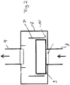
- The
vent valve 1 according to the invention can be designed as a pure pressure holding valve or, alternatively, as part of a normal service vent valve with a roll-over function on a fuel tank. It comprises, for example, a valve housing 2 having a first connection 3 to a fuel tank (not shown) and asecond connection 4, which can be connected to a vent line leading to a fuel vapour filter. The first connection 3 comprises a vent opening 5, which is either connected directly to the compensating volume of a fuel tank or to a vent line from the fuel tank. The valve housing 2 of thevent valve 1 can, for example, be connected directly to the tank wall of a fuel tank or can be welded thereto. - A valve element in the form of a ball 6 (first illustrative example not representing the invention) is arranged within the valve housing 2, for example.
- In the illustrative example shown in
figure 1 , theball 6 is arranged so as to be able to move freely in atube section 7, which forms a valve element guide. - An encircling collar around the vent opening 5 is provided as a
valve seat 8, and is closed by theball 6 in the rest position. As the valve element, theball 6 is held in the position in which it closes the vent opening 5 purely by virtue of its mass, i.e. by the force of gravity. The mass of the ball determines the closing force of the valve. The clear width of thetube section 7 is larger than the diameter of theball 6 by an amount such that, when the fuel tank or the motor vehicle in which the latter is installed is in a tilted position or due to driving dynamics, deflection of theball 6 out of the centre of the vent opening 5 as defined by thevalve seat 8 is possible. By virtue of this possibility, theball 6 partially exposes the cross section of the vent opening 5 when the vehicle is in a tilted position or when there is deceleration or acceleration of the vehicle, thus enabling pressure compensation to take place between the fuel tank and the surroundings. - In order to minimize the pressure loss in the event of a response of the
vent valve 1 when the valve element, i.e. theball 6, returns to the initial position thereof, in which it completely closes the vent opening 5, first relief openings (10) are provided at the edge in thetube section 7, approximately at the level of thevalve seat 8, forming a flow bypass for the pressure loss caused by the valve element orball 6, irrespective of the tilted position of the vehicle. - Owing to this simple and effective measure, the switching hysteresis of the
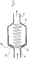
vent valve 1 is significantly reduced. - In the variant of the
vent valve 1 shown inFigure 2 , in which parts which are the same are provided with the same reference signs, the valve element is designed as a piston 9. The piston 9 is likewise arranged with play in thetube section 7, allowing it to perform a slight wobbling/tilting movement within thetube section 7. Since deflection of the piston 9 in a manner corresponding to that in the illustrative embodiment shown inFigure 1 is not desired and not necessary, the size of the gap between the piston 9 and thetube section 7 is somewhat smaller than in the first illustrative embodiment. As a result, the pressure loss due to the valve element would normally be greater in the illustrative embodiment according toFigure 2 . Owing to thefirst relief opening 10 provided in thetube section 7, the switching behaviour of the piston is essentially independent of the gap flow which arises between the piston 9 and thetube section 7. - In the illustrative embodiment according to
Figure 2 too, the piston 9 can be held in the position in which it closes the vent opening 5 purely by the force of gravity. As an alternative, it is possible to hold the piston 9 in the closed position by spring loading. - The piston 9 and the
tube section 7 have mutually complimentary circular cross sections but, of course, the invention is not restricted to such a cross-sectional geometry. - It is also possible for a plate to be provided as a valve element instead of a piston 9.
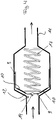
- In the illustrative example of the
vent valve 1 shown inFigure 3 , which does not represent the invention, it is arranged in avent line 11 as a pure pressure holding valve. Accordingly, the valve element is designed as a piston 9 loaded by aspring 13. The piston 9 has aconical sealing surface 12, which interacts with a funnel-shapedvalve seat 8. In the region of theencircling sealing surface 12, the piston 9 is provided withfirst relief openings 10 in the form of bores, through which gas can flow as long as the sealingsurface 12 is not in thevalve seat 8, ensuring that the pressure losses associated with the piston 9 moving in thevalve seat 8 are minimal. Another illustrative example of thevent valve 1, which does not represent the invention, is shown inFigure 4 . The variant of thevent valve 1 illustrated inFigure 4 corresponds to the variant of the vent valve shown inFigure 3 . Components which are the same are provided with the same reference signs. The variant of thevent valve 1 shown inFigure 4 differs from that shown inFigure 3 in that a second relief opening 14 is provided in the end face of the piston 9 and is permanently open. This relief opening 14 is embodied as a somewhat smaller relief bore and allows an intended small amount of leakage through thevent valve 1. Such leakage ensures that the liquid column in the feed pipe of the fuel tank falls after a certain time once the fuel pump nozzle is switched off. The delay is set in such a way that the user cannot immediately add more fuel. Moreover, the second relief opening 14 serves to compensate for any vacuum in the tank. - A further illustrative example of the
vent valve 1, which does not represent the invention, is illustrated inFigures 5 and 6 . This fifth variant of thevent valve 1 corresponds essentially to the variant illustrated inFigure 4 , with the difference that anonreturn valve element 15 is inserted into the second relief opening 14. This opens the second relief opening 14 if there is a vacuum in the tank, and closes it when there is excess pressure. -
- 1
- vent valve
- 2
- valve housing
- 3
- first connection
- 4
- second connection
- 5
- vent opening
- 6
- ball
- 7
- tube section
- 8
- valve seat
- 9
- piston
- 10
- first relief opening
- 11
- vent line
- 12
- sealing surface
- 13
- spring
- 14
- second relief opening
- 15
- nonreturn valve element
Claims (5)
- Vent valve (1) for controlling the internal tank pressure of a motor vehicle fuel tank,having at least one valve housing (2)having at least one first connection (3) to the fuel tank and at least one second connection (4), which can be connected to a vent line leading to a fuel vapour filter,having at least one valve element (6; 9), which is held in a valve seat (8) in a position in which it closes the first connection (3) by the force of gravity and/or by spring loading and, after a given pressure threshold is exceeded, is raised from the valve seat (8) and, when a given pressure threshold is undershot, returns to the initial position,wherein the valve element (6; 9) is arranged so that it can move within a valve element guide (7),wherein the valve element guide (7) has at least one first relief opening (10), which forms a bypass for a gap flow which arises during a return movement of the valve element,wherein the first relief opening (10) is arranged approximately at the level of the valve seat (8) or below the valve seat (8), in relation to the direction of flow through the valve,characterized in that a piston (9) or a plate is provided as a valve element.
- Vent valve (1) according to either of Claims 1, characterized in that at least one cylinder, in which the valve element is arranged so that it can move axially, is provided as a valve element guide.
- Vent valve (1) according to one of Claims 1 to 2, characterized in that the first relief opening (10) in the valve element guide is arranged to the outside of the valve seat (8) .
- Vent valve according to one of Claims 1-3, characterized in that the valve element (9) has at least one second relief opening (14), which is open permanently in order to obtain forced leakage.
- Vent valve according to one of Claims 1-4, characterized in that the valve element (9) has at least one second relief opening (14), which is closed by means of a nonreturn valve acting counter to the direction of closing of the vent valve (1).
Priority Applications (1)
| Application Number | Priority Date | Filing Date | Title |
|---|---|---|---|
| EP17200079.6A EP3342616B2 (en) | 2011-10-26 | 2012-09-20 | Vent valve |
Applications Claiming Priority (2)
| Application Number | Priority Date | Filing Date | Title |
|---|---|---|---|
| DE102011116941A DE102011116941A1 (en) | 2011-10-26 | 2011-10-26 | vent valve |
| PCT/EP2012/003920 WO2013060404A2 (en) | 2011-10-26 | 2012-09-20 | Vent valve |
Related Child Applications (2)
| Application Number | Title | Priority Date | Filing Date |
|---|---|---|---|
| EP17200079.6A Division EP3342616B2 (en) | 2011-10-26 | 2012-09-20 | Vent valve |
| EP17200079.6A Division-Into EP3342616B2 (en) | 2011-10-26 | 2012-09-20 | Vent valve |
Publications (3)
| Publication Number | Publication Date |
|---|---|
| EP2771200A2 EP2771200A2 (en) | 2014-09-03 |
| EP2771200B1 EP2771200B1 (en) | 2017-11-08 |
| EP2771200B2 true EP2771200B2 (en) | 2022-04-06 |
Family
ID=46934509
Family Applications (2)
| Application Number | Title | Priority Date | Filing Date |
|---|---|---|---|
| EP12765999.3A Active EP2771200B2 (en) | 2011-10-26 | 2012-09-20 | Vent valve |
| EP17200079.6A Active EP3342616B2 (en) | 2011-10-26 | 2012-09-20 | Vent valve |
Family Applications After (1)
| Application Number | Title | Priority Date | Filing Date |
|---|---|---|---|
| EP17200079.6A Active EP3342616B2 (en) | 2011-10-26 | 2012-09-20 | Vent valve |
Country Status (10)
| Country | Link |
|---|---|
| US (1) | US10245941B2 (en) |
| EP (2) | EP2771200B2 (en) |
| JP (1) | JP2014530789A (en) |
| KR (1) | KR20140084270A (en) |
| CN (2) | CN103889760A (en) |
| BR (1) | BR112014010017B1 (en) |
| DE (1) | DE102011116941A1 (en) |
| IN (1) | IN2014CN03848A (en) |
| RU (1) | RU2556812C1 (en) |
| WO (1) | WO2013060404A2 (en) |
Families Citing this family (10)
| Publication number | Priority date | Publication date | Assignee | Title |
|---|---|---|---|---|
| CN104006253B (en) * | 2014-06-03 | 2017-03-01 | 河南科技大学 | A kind of one drags three spherical self adaptation valve actuating mechanisms |
| WO2016160782A1 (en) * | 2015-03-29 | 2016-10-06 | Eaton Corporation | Fuel system having vent point valve |
| KR101734698B1 (en) | 2015-10-30 | 2017-05-11 | 현대자동차주식회사 | Quick connector of fuel line |
| CN105927770A (en) * | 2016-07-14 | 2016-09-07 | 邹敏 | Automatic pressure regulation device for gas |
| CN107314585A (en) * | 2017-08-09 | 2017-11-03 | 苏州泰隆制冷有限公司 | A kind of idle call adjustable-flow distributor |
| CN111886152B (en) * | 2018-06-13 | 2024-03-01 | 沃尔沃卡车集团 | Flow regulating device, fuel management system comprising such a device and motor vehicle comprising such a system |
| CN113454327B (en) * | 2019-02-20 | 2023-06-06 | 皮尔伯格有限责任公司 | Flow restrictor for fuel shut-off valve |
| CN110265887B (en) * | 2019-06-28 | 2020-05-29 | 宁夏升世隆泰电气有限公司 | Adjustable cubical switchboard pressure relief device |
| EP4135909A4 (en) * | 2020-04-16 | 2024-02-21 | Rpm Ind Llc | Modular container and system including same |
| CN113353476B (en) * | 2021-06-09 | 2022-04-15 | 中车太原机车车辆有限公司 | Air supplement and exhaust device and container suitable for powder tank container |
Citations (8)
| Publication number | Priority date | Publication date | Assignee | Title |
|---|---|---|---|---|
| US5666989A (en) † | 1994-11-08 | 1997-09-16 | Stant Manufacturing Inc. | Tank venting control assembly |
| EP0853014A1 (en) † | 1997-01-14 | 1998-07-15 | ERGOM MATERIE PLASTICHE S.p.A | Gas pressure relief valve unit particularly for fuel vapours |
| DE10209369A1 (en) † | 2002-03-02 | 2003-06-18 | Zf Lenksysteme Gmbh | Pressure limiting valve has spring cavity closed off by sliding closing member |
| EP1697157A1 (en) † | 2003-12-23 | 2006-09-06 | A. Kayser Automotive Systems GmbH | Bleed valve |
| GB2453837A (en) † | 2007-10-19 | 2009-04-22 | Gen Electric | Vent apparatus for filling an oil tank |
| US7604063B2 (en) † | 2005-02-10 | 2009-10-20 | Benny Donald Mashburn | Flow valve and method |
| WO2010131099A1 (en) † | 2009-05-11 | 2010-11-18 | Eaton Corporation | Fuel vapor vent valve with dynamic pressure relief |
| US8286658B2 (en) † | 2005-06-07 | 2012-10-16 | Stant Usa Corp. | Roll-over valve with shared overfill protection and vacuum relief |
Family Cites Families (26)
| Publication number | Priority date | Publication date | Assignee | Title |
|---|---|---|---|---|
| US4310145A (en) | 1978-05-22 | 1982-01-12 | Acf Industries, Incorporated | Combination top operable and bottom operable tank lading valve assembly |
| JP2559486B2 (en) † | 1989-04-17 | 1996-12-04 | 日産自動車株式会社 | Fuel shutoff valve device for fuel tank |
| US5253668A (en) * | 1993-02-18 | 1993-10-19 | G.T. Products, Inc. | Smooth-opening, low-hysteresis ball head valve |
| US5590697A (en) | 1994-08-24 | 1997-01-07 | G. T. Products, Inc. | Onboard vapor recovery system with two-stage shutoff valve |
| US5595209A (en) | 1995-03-29 | 1997-01-21 | Airtrol Components Inc. | Fluid pressure regulator establishing a stable output fluid pressure |
| US5687778A (en) * | 1995-05-01 | 1997-11-18 | Stant Manufacturing Inc. | Dual valve tank venting system |
| FR2738612B1 (en) * | 1995-09-08 | 1997-10-24 | Cogema | SAFETY VALVE FOR A CONTAINMENT ENCLOSURE |
| AU720237B2 (en) | 1996-12-09 | 2000-05-25 | International Marketing, Inc. | Method and sealing valve unit for controlling fluid flow through a passage |
| JP2000199577A (en) * | 1999-01-08 | 2000-07-18 | Aisan Ind Co Ltd | Check device |
| JP4656709B2 (en) * | 2000-09-21 | 2011-03-23 | カヤバ工業株式会社 | Pressure control valve |
| FR2819874B1 (en) * | 2001-01-25 | 2004-01-23 | Eaton Sa Monaco | INTERNAL GAS PRESSURE CONTROL VALVE OF A TANK |
| US20030094204A1 (en) * | 2001-11-20 | 2003-05-22 | Varian Semiconductor Equipment Associates, Inc. | Pressure relief valve |
| JP2003240143A (en) * | 2002-02-14 | 2003-08-27 | Nifco Inc | Two-way valve |
| JP2006044586A (en) * | 2004-08-06 | 2006-02-16 | Piolax Inc | Check valve for fuel tank |
| US7207347B2 (en) * | 2004-08-23 | 2007-04-24 | Raval A.S.C. Ltd. | Dual function valve for fuel tank |
| JP2006234159A (en) * | 2004-11-24 | 2006-09-07 | Toyoda Gosei Co Ltd | Fuel cutoff valve |
| US20060192168A1 (en) * | 2005-02-17 | 2006-08-31 | Thompson Bruce A | Suction actuated gravity deactivated ball valve |
| US7249595B2 (en) * | 2005-03-16 | 2007-07-31 | Eaton Corporation | Vapor vent valve with pressure relief function integrated to carbon canister |
| US20060213553A1 (en) | 2005-03-22 | 2006-09-28 | Vaughn K. Mills & Kenneth M. Spink | Low profile overfill limit device with reverse flow capability |
| US7997293B2 (en) * | 2006-07-13 | 2011-08-16 | Filtertek, Inc. | Valve apparatus, combination filter valve assemblies and devices, systems, and methods including the same |
| KR100800174B1 (en) | 2006-10-20 | 2008-02-01 | 한국기계연구원 | Wafer cleaning module using megasonic |
| US8171952B2 (en) * | 2008-02-01 | 2012-05-08 | Eaton Corporation | Multi-function control valve for fuel vapor system |
| US8054627B2 (en) | 2008-02-19 | 2011-11-08 | International Business Machines Corporation | System and method for determining air density based on temperature sensor data |
| ATE531592T1 (en) * | 2008-05-21 | 2011-11-15 | Parker Hannifin Corp | BREATHER WITH HYDRAULIC FLUID SYSTEM WITH INDEPENDENT INLET/OUTLET FLOW PATHS |
| JP5012664B2 (en) * | 2008-05-28 | 2012-08-29 | 豊田合成株式会社 | Fuel tank venting device |
| DE102010015030A1 (en) * | 2009-10-08 | 2011-04-14 | Daimler Ag | Additional energy-working pressure control valve, particularly pyrotechnic vent valve for gas-driven security devices of vehicles , has valve housing with inlet and outlet |
-
2011
- 2011-10-26 DE DE102011116941A patent/DE102011116941A1/en not_active Ceased
-
2012
- 2012-09-20 BR BR112014010017-9A patent/BR112014010017B1/en active IP Right Grant
- 2012-09-20 WO PCT/EP2012/003920 patent/WO2013060404A2/en active Application Filing
- 2012-09-20 KR KR1020147013940A patent/KR20140084270A/en active Search and Examination
- 2012-09-20 EP EP12765999.3A patent/EP2771200B2/en active Active
- 2012-09-20 US US14/354,790 patent/US10245941B2/en active Active
- 2012-09-20 EP EP17200079.6A patent/EP3342616B2/en active Active
- 2012-09-20 IN IN3848CHN2014 patent/IN2014CN03848A/en unknown
- 2012-09-20 RU RU2014121004/11A patent/RU2556812C1/en active
- 2012-09-20 JP JP2014537507A patent/JP2014530789A/en active Pending
- 2012-09-20 CN CN201280052509.XA patent/CN103889760A/en active Pending
- 2012-09-20 CN CN201910195673.XA patent/CN109910598A/en active Pending
Patent Citations (8)
| Publication number | Priority date | Publication date | Assignee | Title |
|---|---|---|---|---|
| US5666989A (en) † | 1994-11-08 | 1997-09-16 | Stant Manufacturing Inc. | Tank venting control assembly |
| EP0853014A1 (en) † | 1997-01-14 | 1998-07-15 | ERGOM MATERIE PLASTICHE S.p.A | Gas pressure relief valve unit particularly for fuel vapours |
| DE10209369A1 (en) † | 2002-03-02 | 2003-06-18 | Zf Lenksysteme Gmbh | Pressure limiting valve has spring cavity closed off by sliding closing member |
| EP1697157A1 (en) † | 2003-12-23 | 2006-09-06 | A. Kayser Automotive Systems GmbH | Bleed valve |
| US7604063B2 (en) † | 2005-02-10 | 2009-10-20 | Benny Donald Mashburn | Flow valve and method |
| US8286658B2 (en) † | 2005-06-07 | 2012-10-16 | Stant Usa Corp. | Roll-over valve with shared overfill protection and vacuum relief |
| GB2453837A (en) † | 2007-10-19 | 2009-04-22 | Gen Electric | Vent apparatus for filling an oil tank |
| WO2010131099A1 (en) † | 2009-05-11 | 2010-11-18 | Eaton Corporation | Fuel vapor vent valve with dynamic pressure relief |
Non-Patent Citations (1)
| Title |
|---|
| "Fuel Vapor systems - Roll Over Valves with Anti- Trickle Valve Feature", EATON CORPORATION, 2005 † |
Also Published As
| Publication number | Publication date |
|---|---|
| RU2556812C1 (en) | 2015-07-20 |
| EP3342616A1 (en) | 2018-07-04 |
| US20140305956A1 (en) | 2014-10-16 |
| EP3342616B2 (en) | 2022-12-07 |
| US10245941B2 (en) | 2019-04-02 |
| CN109910598A (en) | 2019-06-21 |
| BR112014010017B1 (en) | 2021-06-22 |
| WO2013060404A3 (en) | 2013-07-25 |
| KR20140084270A (en) | 2014-07-04 |
| EP2771200A2 (en) | 2014-09-03 |
| BR112014010017A2 (en) | 2017-04-25 |
| DE102011116941A1 (en) | 2013-05-02 |
| EP3342616B1 (en) | 2019-03-06 |
| WO2013060404A2 (en) | 2013-05-02 |
| EP2771200B1 (en) | 2017-11-08 |
| IN2014CN03848A (en) | 2015-09-04 |
| CN103889760A (en) | 2014-06-25 |
| JP2014530789A (en) | 2014-11-20 |
Similar Documents
| Publication | Publication Date | Title |
|---|---|---|
| EP2771200B2 (en) | Vent valve | |
| JP4733439B2 (en) | Automotive fuel system | |
| US6311675B2 (en) | Vent valve and fuel pump module | |
| US8789557B2 (en) | Ventilation arrangement for a fuel tank | |
| WO2004079242A1 (en) | Safety valve | |
| US6848463B2 (en) | Vapor vent valve | |
| US7886759B2 (en) | Fuel cutoff valve | |
| JP3909837B2 (en) | Fuel tank fuel spill regulating device | |
| EP1221566A1 (en) | Noise dampened float type fuel vapor vent valve | |
| EP2632757B1 (en) | Fuel tank for motor vehicles | |
| JP5839740B2 (en) | Fuel tank or secondary fluid tank for automobile | |
| US8291929B2 (en) | Dual float rollover valve | |
| US7055556B2 (en) | Controlling vapor recirculation during refueling of a tank through a filler tube from a dispensing nozzle | |
| JP2005180264A (en) | Structure of evaporation gas control valve | |
| JP2004353518A (en) | Tank fill-up regulation valve | |
| JP5807587B2 (en) | Fuel tank system | |
| CN111770849A (en) | Evaporative emissions fuel tank venting system with drain pump | |
| WO2017163661A1 (en) | Fuel tank venting control valve | |
| US20040089340A1 (en) | Fuel cut-off valve device | |
| US6581621B1 (en) | Valve and fuel tank provided with a valve for a motor vehicle | |
| EP3645330B1 (en) | A ventilation flow rate regulator for a pressurized vehicle tank | |
| JP5807527B2 (en) | Fuel tank system | |
| JP6874579B2 (en) | Fuel shutoff valve | |
| WO2019228673A1 (en) | Electronic evaporative emissions control system having electronically controlled roll over valve | |
| JP4586784B2 (en) | Fuel shut-off valve |
Legal Events
| Date | Code | Title | Description |
|---|---|---|---|
| PUAI | Public reference made under article 153(3) epc to a published international application that has entered the european phase |
Free format text: ORIGINAL CODE: 0009012 |
|
| 17P | Request for examination filed |
Effective date: 20140515 |
|
| AK | Designated contracting states |
Kind code of ref document: A2 Designated state(s): AL AT BE BG CH CY CZ DE DK EE ES FI FR GB GR HR HU IE IS IT LI LT LU LV MC MK MT NL NO PL PT RO RS SE SI SK SM TR |
|
| DAX | Request for extension of the european patent (deleted) | ||
| 17Q | First examination report despatched |
Effective date: 20160916 |
|
| STAA | Information on the status of an ep patent application or granted ep patent |
Free format text: STATUS: EXAMINATION IS IN PROGRESS |
|
| GRAP | Despatch of communication of intention to grant a patent |
Free format text: ORIGINAL CODE: EPIDOSNIGR1 |
|
| STAA | Information on the status of an ep patent application or granted ep patent |
Free format text: STATUS: GRANT OF PATENT IS INTENDED |
|
| INTG | Intention to grant announced |
Effective date: 20170829 |
|
| GRAS | Grant fee paid |
Free format text: ORIGINAL CODE: EPIDOSNIGR3 |
|
| GRAA | (expected) grant |
Free format text: ORIGINAL CODE: 0009210 |
|
| STAA | Information on the status of an ep patent application or granted ep patent |
Free format text: STATUS: THE PATENT HAS BEEN GRANTED |
|
| AK | Designated contracting states |
Kind code of ref document: B1 Designated state(s): AL AT BE BG CH CY CZ DE DK EE ES FI FR GB GR HR HU IE IS IT LI LT LU LV MC MK MT NL NO PL PT RO RS SE SI SK SM TR |
|
| REG | Reference to a national code |
Ref country code: GB Ref legal event code: FG4D |
|
| REG | Reference to a national code |
Ref country code: CH Ref legal event code: EP Ref country code: AT Ref legal event code: REF Ref document number: 943797 Country of ref document: AT Kind code of ref document: T Effective date: 20171115 |
|
| REG | Reference to a national code |
Ref country code: IE Ref legal event code: FG4D |
|
| REG | Reference to a national code |
Ref country code: DE Ref legal event code: R096 Ref document number: 602012039518 Country of ref document: DE |
|
| REG | Reference to a national code |
Ref country code: NL Ref legal event code: MP Effective date: 20171108 |
|
| REG | Reference to a national code |
Ref country code: LT Ref legal event code: MG4D |
|
| REG | Reference to a national code |
Ref country code: AT Ref legal event code: MK05 Ref document number: 943797 Country of ref document: AT Kind code of ref document: T Effective date: 20171108 |
|
| PG25 | Lapsed in a contracting state [announced via postgrant information from national office to epo] |
Ref country code: ES Free format text: LAPSE BECAUSE OF FAILURE TO SUBMIT A TRANSLATION OF THE DESCRIPTION OR TO PAY THE FEE WITHIN THE PRESCRIBED TIME-LIMIT Effective date: 20171108 Ref country code: LT Free format text: LAPSE BECAUSE OF FAILURE TO SUBMIT A TRANSLATION OF THE DESCRIPTION OR TO PAY THE FEE WITHIN THE PRESCRIBED TIME-LIMIT Effective date: 20171108 Ref country code: SE Free format text: LAPSE BECAUSE OF FAILURE TO SUBMIT A TRANSLATION OF THE DESCRIPTION OR TO PAY THE FEE WITHIN THE PRESCRIBED TIME-LIMIT Effective date: 20171108 Ref country code: NO Free format text: LAPSE BECAUSE OF FAILURE TO SUBMIT A TRANSLATION OF THE DESCRIPTION OR TO PAY THE FEE WITHIN THE PRESCRIBED TIME-LIMIT Effective date: 20180208 Ref country code: NL Free format text: LAPSE BECAUSE OF FAILURE TO SUBMIT A TRANSLATION OF THE DESCRIPTION OR TO PAY THE FEE WITHIN THE PRESCRIBED TIME-LIMIT Effective date: 20171108 Ref country code: FI Free format text: LAPSE BECAUSE OF FAILURE TO SUBMIT A TRANSLATION OF THE DESCRIPTION OR TO PAY THE FEE WITHIN THE PRESCRIBED TIME-LIMIT Effective date: 20171108 |
|
| PG25 | Lapsed in a contracting state [announced via postgrant information from national office to epo] |
Ref country code: BG Free format text: LAPSE BECAUSE OF FAILURE TO SUBMIT A TRANSLATION OF THE DESCRIPTION OR TO PAY THE FEE WITHIN THE PRESCRIBED TIME-LIMIT Effective date: 20180208 Ref country code: AT Free format text: LAPSE BECAUSE OF FAILURE TO SUBMIT A TRANSLATION OF THE DESCRIPTION OR TO PAY THE FEE WITHIN THE PRESCRIBED TIME-LIMIT Effective date: 20171108 Ref country code: RS Free format text: LAPSE BECAUSE OF FAILURE TO SUBMIT A TRANSLATION OF THE DESCRIPTION OR TO PAY THE FEE WITHIN THE PRESCRIBED TIME-LIMIT Effective date: 20171108 Ref country code: GR Free format text: LAPSE BECAUSE OF FAILURE TO SUBMIT A TRANSLATION OF THE DESCRIPTION OR TO PAY THE FEE WITHIN THE PRESCRIBED TIME-LIMIT Effective date: 20180209 Ref country code: LV Free format text: LAPSE BECAUSE OF FAILURE TO SUBMIT A TRANSLATION OF THE DESCRIPTION OR TO PAY THE FEE WITHIN THE PRESCRIBED TIME-LIMIT Effective date: 20171108 Ref country code: IS Free format text: LAPSE BECAUSE OF FAILURE TO SUBMIT A TRANSLATION OF THE DESCRIPTION OR TO PAY THE FEE WITHIN THE PRESCRIBED TIME-LIMIT Effective date: 20180308 Ref country code: HR Free format text: LAPSE BECAUSE OF FAILURE TO SUBMIT A TRANSLATION OF THE DESCRIPTION OR TO PAY THE FEE WITHIN THE PRESCRIBED TIME-LIMIT Effective date: 20171108 |
|
| PG25 | Lapsed in a contracting state [announced via postgrant information from national office to epo] |
Ref country code: SK Free format text: LAPSE BECAUSE OF FAILURE TO SUBMIT A TRANSLATION OF THE DESCRIPTION OR TO PAY THE FEE WITHIN THE PRESCRIBED TIME-LIMIT Effective date: 20171108 Ref country code: CZ Free format text: LAPSE BECAUSE OF FAILURE TO SUBMIT A TRANSLATION OF THE DESCRIPTION OR TO PAY THE FEE WITHIN THE PRESCRIBED TIME-LIMIT Effective date: 20171108 Ref country code: CY Free format text: LAPSE BECAUSE OF FAILURE TO SUBMIT A TRANSLATION OF THE DESCRIPTION OR TO PAY THE FEE WITHIN THE PRESCRIBED TIME-LIMIT Effective date: 20171108 Ref country code: EE Free format text: LAPSE BECAUSE OF FAILURE TO SUBMIT A TRANSLATION OF THE DESCRIPTION OR TO PAY THE FEE WITHIN THE PRESCRIBED TIME-LIMIT Effective date: 20171108 Ref country code: DK Free format text: LAPSE BECAUSE OF FAILURE TO SUBMIT A TRANSLATION OF THE DESCRIPTION OR TO PAY THE FEE WITHIN THE PRESCRIBED TIME-LIMIT Effective date: 20171108 |
|
| REG | Reference to a national code |
Ref country code: DE Ref legal event code: R026 Ref document number: 602012039518 Country of ref document: DE |
|
| PLBI | Opposition filed |
Free format text: ORIGINAL CODE: 0009260 |
|
| PLAX | Notice of opposition and request to file observation + time limit sent |
Free format text: ORIGINAL CODE: EPIDOSNOBS2 |
|
| PG25 | Lapsed in a contracting state [announced via postgrant information from national office to epo] |
Ref country code: RO Free format text: LAPSE BECAUSE OF FAILURE TO SUBMIT A TRANSLATION OF THE DESCRIPTION OR TO PAY THE FEE WITHIN THE PRESCRIBED TIME-LIMIT Effective date: 20171108 Ref country code: IT Free format text: LAPSE BECAUSE OF FAILURE TO SUBMIT A TRANSLATION OF THE DESCRIPTION OR TO PAY THE FEE WITHIN THE PRESCRIBED TIME-LIMIT Effective date: 20171108 Ref country code: SM Free format text: LAPSE BECAUSE OF FAILURE TO SUBMIT A TRANSLATION OF THE DESCRIPTION OR TO PAY THE FEE WITHIN THE PRESCRIBED TIME-LIMIT Effective date: 20171108 Ref country code: PL Free format text: LAPSE BECAUSE OF FAILURE TO SUBMIT A TRANSLATION OF THE DESCRIPTION OR TO PAY THE FEE WITHIN THE PRESCRIBED TIME-LIMIT Effective date: 20171108 |
|
| 26 | Opposition filed |
Opponent name: PLASTIC OMNIUM ADVANCED INNOVATION AND RESEARCH Effective date: 20180807 |
|
| REG | Reference to a national code |
Ref country code: FR Ref legal event code: PLFP Year of fee payment: 7 |
|
| PG25 | Lapsed in a contracting state [announced via postgrant information from national office to epo] |
Ref country code: SI Free format text: LAPSE BECAUSE OF FAILURE TO SUBMIT A TRANSLATION OF THE DESCRIPTION OR TO PAY THE FEE WITHIN THE PRESCRIBED TIME-LIMIT Effective date: 20171108 |
|
| PLBB | Reply of patent proprietor to notice(s) of opposition received |
Free format text: ORIGINAL CODE: EPIDOSNOBS3 |
|
| PG25 | Lapsed in a contracting state [announced via postgrant information from national office to epo] |
Ref country code: MC Free format text: LAPSE BECAUSE OF FAILURE TO SUBMIT A TRANSLATION OF THE DESCRIPTION OR TO PAY THE FEE WITHIN THE PRESCRIBED TIME-LIMIT Effective date: 20171108 |
|
| REG | Reference to a national code |
Ref country code: CH Ref legal event code: PL |
|
| REG | Reference to a national code |
Ref country code: BE Ref legal event code: MM Effective date: 20180930 |
|
| REG | Reference to a national code |
Ref country code: IE Ref legal event code: MM4A |
|
| PG25 | Lapsed in a contracting state [announced via postgrant information from national office to epo] |
Ref country code: LU Free format text: LAPSE BECAUSE OF NON-PAYMENT OF DUE FEES Effective date: 20180920 |
|
| PG25 | Lapsed in a contracting state [announced via postgrant information from national office to epo] |
Ref country code: IE Free format text: LAPSE BECAUSE OF NON-PAYMENT OF DUE FEES Effective date: 20180920 |
|
| PG25 | Lapsed in a contracting state [announced via postgrant information from national office to epo] |
Ref country code: CH Free format text: LAPSE BECAUSE OF NON-PAYMENT OF DUE FEES Effective date: 20180930 Ref country code: LI Free format text: LAPSE BECAUSE OF NON-PAYMENT OF DUE FEES Effective date: 20180930 Ref country code: BE Free format text: LAPSE BECAUSE OF NON-PAYMENT OF DUE FEES Effective date: 20180930 |
|
| PG25 | Lapsed in a contracting state [announced via postgrant information from national office to epo] |
Ref country code: MT Free format text: LAPSE BECAUSE OF NON-PAYMENT OF DUE FEES Effective date: 20180920 |
|
| PG25 | Lapsed in a contracting state [announced via postgrant information from national office to epo] |
Ref country code: TR Free format text: LAPSE BECAUSE OF FAILURE TO SUBMIT A TRANSLATION OF THE DESCRIPTION OR TO PAY THE FEE WITHIN THE PRESCRIBED TIME-LIMIT Effective date: 20171108 |
|
| PG25 | Lapsed in a contracting state [announced via postgrant information from national office to epo] |
Ref country code: PT Free format text: LAPSE BECAUSE OF FAILURE TO SUBMIT A TRANSLATION OF THE DESCRIPTION OR TO PAY THE FEE WITHIN THE PRESCRIBED TIME-LIMIT Effective date: 20171108 Ref country code: HU Free format text: LAPSE BECAUSE OF FAILURE TO SUBMIT A TRANSLATION OF THE DESCRIPTION OR TO PAY THE FEE WITHIN THE PRESCRIBED TIME-LIMIT; INVALID AB INITIO Effective date: 20120920 |
|
| PG25 | Lapsed in a contracting state [announced via postgrant information from national office to epo] |
Ref country code: MK Free format text: LAPSE BECAUSE OF NON-PAYMENT OF DUE FEES Effective date: 20171108 |
|
| PG25 | Lapsed in a contracting state [announced via postgrant information from national office to epo] |
Ref country code: AL Free format text: LAPSE BECAUSE OF FAILURE TO SUBMIT A TRANSLATION OF THE DESCRIPTION OR TO PAY THE FEE WITHIN THE PRESCRIBED TIME-LIMIT Effective date: 20171108 |
|
| APBM | Appeal reference recorded |
Free format text: ORIGINAL CODE: EPIDOSNREFNO |
|
| APBP | Date of receipt of notice of appeal recorded |
Free format text: ORIGINAL CODE: EPIDOSNNOA2O |
|
| APAH | Appeal reference modified |
Free format text: ORIGINAL CODE: EPIDOSCREFNO |
|
| APBU | Appeal procedure closed |
Free format text: ORIGINAL CODE: EPIDOSNNOA9O |
|
| PUAH | Patent maintained in amended form |
Free format text: ORIGINAL CODE: 0009272 |
|
| STAA | Information on the status of an ep patent application or granted ep patent |
Free format text: STATUS: PATENT MAINTAINED AS AMENDED |
|
| 27A | Patent maintained in amended form |
Effective date: 20220406 |
|
| AK | Designated contracting states |
Kind code of ref document: B2 Designated state(s): AL AT BE BG CH CY CZ DE DK EE ES FI FR GB GR HR HU IE IS IT LI LT LU LV MC MK MT NL NO PL PT RO RS SE SI SK SM TR |
|
| REG | Reference to a national code |
Ref country code: DE Ref legal event code: R102 Ref document number: 602012039518 Country of ref document: DE |
|
| P01 | Opt-out of the competence of the unified patent court (upc) registered |
Effective date: 20230526 |
|
| PGFP | Annual fee paid to national office [announced via postgrant information from national office to epo] |
Ref country code: GB Payment date: 20230920 Year of fee payment: 12 |
|
| PGFP | Annual fee paid to national office [announced via postgrant information from national office to epo] |
Ref country code: FR Payment date: 20230928 Year of fee payment: 12 Ref country code: DE Payment date: 20230825 Year of fee payment: 12 |