EP2770192A2 - Check valve assembly in the intake side of a hydrostatic engine that can be operated as a pump and motor with the same direction of rotation - Google Patents
Check valve assembly in the intake side of a hydrostatic engine that can be operated as a pump and motor with the same direction of rotation Download PDFInfo
- Publication number
- EP2770192A2 EP2770192A2 EP20140153079 EP14153079A EP2770192A2 EP 2770192 A2 EP2770192 A2 EP 2770192A2 EP 20140153079 EP20140153079 EP 20140153079 EP 14153079 A EP14153079 A EP 14153079A EP 2770192 A2 EP2770192 A2 EP 2770192A2
- Authority
- EP
- European Patent Office
- Prior art keywords
- engine
- check valve
- pressure
- valve
- hydrostatic
- Prior art date
- Legal status (The legal status is an assumption and is not a legal conclusion. Google has not performed a legal analysis and makes no representation as to the accuracy of the status listed.)
- Withdrawn
Links
- 230000002706 hydrostatic effect Effects 0.000 title claims abstract description 77
- 238000002485 combustion reaction Methods 0.000 claims abstract description 118
- 230000000903 blocking effect Effects 0.000 claims abstract description 19
- 238000006073 displacement reaction Methods 0.000 claims description 34
- 239000007858 starting material Substances 0.000 claims description 31
- 239000012530 fluid Substances 0.000 claims description 26
- 238000004891 communication Methods 0.000 claims description 5
- 230000008878 coupling Effects 0.000 claims description 5
- 238000010168 coupling process Methods 0.000 claims description 5
- 238000005859 coupling reaction Methods 0.000 claims description 5
- 230000004044 response Effects 0.000 claims description 3
- 150000001875 compounds Chemical class 0.000 abstract 1
- 230000006870 function Effects 0.000 description 32
- 238000010276 construction Methods 0.000 description 14
- 238000000034 method Methods 0.000 description 14
- 230000008569 process Effects 0.000 description 14
- 230000008901 benefit Effects 0.000 description 11
- 238000013461 design Methods 0.000 description 6
- 238000011161 development Methods 0.000 description 4
- 230000005540 biological transmission Effects 0.000 description 3
- 210000002023 somite Anatomy 0.000 description 3
- 230000006835 compression Effects 0.000 description 2
- 238000007906 compression Methods 0.000 description 2
- 238000010586 diagram Methods 0.000 description 2
- 239000000446 fuel Substances 0.000 description 2
- 241000219310 Beta vulgaris subsp. vulgaris Species 0.000 description 1
- 241001295925 Gegenes Species 0.000 description 1
- 244000061456 Solanum tuberosum Species 0.000 description 1
- 235000002595 Solanum tuberosum Nutrition 0.000 description 1
- 235000021536 Sugar beet Nutrition 0.000 description 1
- 239000004459 forage Substances 0.000 description 1
- 239000002655 kraft paper Substances 0.000 description 1
- 230000009347 mechanical transmission Effects 0.000 description 1
- 238000012544 monitoring process Methods 0.000 description 1
- 238000005086 pumping Methods 0.000 description 1
- 230000009467 reduction Effects 0.000 description 1
- 230000003068 static effect Effects 0.000 description 1
- 239000013589 supplement Substances 0.000 description 1
Images


Classifications
-
- F—MECHANICAL ENGINEERING; LIGHTING; HEATING; WEAPONS; BLASTING
- F02—COMBUSTION ENGINES; HOT-GAS OR COMBUSTION-PRODUCT ENGINE PLANTS
- F02B—INTERNAL-COMBUSTION PISTON ENGINES; COMBUSTION ENGINES IN GENERAL
- F02B73/00—Combinations of two or more engines, not otherwise provided for
-
- B—PERFORMING OPERATIONS; TRANSPORTING
- B60—VEHICLES IN GENERAL
- B60K—ARRANGEMENT OR MOUNTING OF PROPULSION UNITS OR OF TRANSMISSIONS IN VEHICLES; ARRANGEMENT OR MOUNTING OF PLURAL DIVERSE PRIME-MOVERS IN VEHICLES; AUXILIARY DRIVES FOR VEHICLES; INSTRUMENTATION OR DASHBOARDS FOR VEHICLES; ARRANGEMENTS IN CONNECTION WITH COOLING, AIR INTAKE, GAS EXHAUST OR FUEL SUPPLY OF PROPULSION UNITS IN VEHICLES
- B60K6/00—Arrangement or mounting of plural diverse prime-movers for mutual or common propulsion, e.g. hybrid propulsion systems comprising electric motors and internal combustion engines ; Control systems therefor, i.e. systems controlling two or more prime movers, or controlling one of these prime movers and any of the transmission, drive or drive units Informative references: mechanical gearings with secondary electric drive F16H3/72; arrangements for handling mechanical energy structurally associated with the dynamo-electric machine H02K7/00; machines comprising structurally interrelated motor and generator parts H02K51/00; dynamo-electric machines not otherwise provided for in H02K see H02K99/00
- B60K6/08—Prime-movers comprising combustion engines and mechanical or fluid energy storing means
- B60K6/12—Prime-movers comprising combustion engines and mechanical or fluid energy storing means by means of a chargeable fluidic accumulator
-
- B—PERFORMING OPERATIONS; TRANSPORTING
- B60—VEHICLES IN GENERAL
- B60W—CONJOINT CONTROL OF VEHICLE SUB-UNITS OF DIFFERENT TYPE OR DIFFERENT FUNCTION; CONTROL SYSTEMS SPECIALLY ADAPTED FOR HYBRID VEHICLES; ROAD VEHICLE DRIVE CONTROL SYSTEMS FOR PURPOSES NOT RELATED TO THE CONTROL OF A PARTICULAR SUB-UNIT
- B60W10/00—Conjoint control of vehicle sub-units of different type or different function
- B60W10/04—Conjoint control of vehicle sub-units of different type or different function including control of propulsion units
- B60W10/06—Conjoint control of vehicle sub-units of different type or different function including control of propulsion units including control of combustion engines
-
- B—PERFORMING OPERATIONS; TRANSPORTING
- B60—VEHICLES IN GENERAL
- B60W—CONJOINT CONTROL OF VEHICLE SUB-UNITS OF DIFFERENT TYPE OR DIFFERENT FUNCTION; CONTROL SYSTEMS SPECIALLY ADAPTED FOR HYBRID VEHICLES; ROAD VEHICLE DRIVE CONTROL SYSTEMS FOR PURPOSES NOT RELATED TO THE CONTROL OF A PARTICULAR SUB-UNIT
- B60W30/00—Purposes of road vehicle drive control systems not related to the control of a particular sub-unit, e.g. of systems using conjoint control of vehicle sub-units, or advanced driver assistance systems for ensuring comfort, stability and safety or drive control systems for propelling or retarding the vehicle
- B60W30/18—Propelling the vehicle
- B60W30/18009—Propelling the vehicle related to particular drive situations
- B60W30/18018—Start-stop drive, e.g. in a traffic jam
-
- F—MECHANICAL ENGINEERING; LIGHTING; HEATING; WEAPONS; BLASTING
- F02—COMBUSTION ENGINES; HOT-GAS OR COMBUSTION-PRODUCT ENGINE PLANTS
- F02N—STARTING OF COMBUSTION ENGINES; STARTING AIDS FOR SUCH ENGINES, NOT OTHERWISE PROVIDED FOR
- F02N7/00—Starting apparatus having fluid-driven auxiliary engines or apparatus
-
- B—PERFORMING OPERATIONS; TRANSPORTING
- B60—VEHICLES IN GENERAL
- B60K—ARRANGEMENT OR MOUNTING OF PROPULSION UNITS OR OF TRANSMISSIONS IN VEHICLES; ARRANGEMENT OR MOUNTING OF PLURAL DIVERSE PRIME-MOVERS IN VEHICLES; AUXILIARY DRIVES FOR VEHICLES; INSTRUMENTATION OR DASHBOARDS FOR VEHICLES; ARRANGEMENTS IN CONNECTION WITH COOLING, AIR INTAKE, GAS EXHAUST OR FUEL SUPPLY OF PROPULSION UNITS IN VEHICLES
- B60K6/00—Arrangement or mounting of plural diverse prime-movers for mutual or common propulsion, e.g. hybrid propulsion systems comprising electric motors and internal combustion engines ; Control systems therefor, i.e. systems controlling two or more prime movers, or controlling one of these prime movers and any of the transmission, drive or drive units Informative references: mechanical gearings with secondary electric drive F16H3/72; arrangements for handling mechanical energy structurally associated with the dynamo-electric machine H02K7/00; machines comprising structurally interrelated motor and generator parts H02K51/00; dynamo-electric machines not otherwise provided for in H02K see H02K99/00
- B60K6/08—Prime-movers comprising combustion engines and mechanical or fluid energy storing means
- B60K6/12—Prime-movers comprising combustion engines and mechanical or fluid energy storing means by means of a chargeable fluidic accumulator
- B60K2006/126—Prime-movers comprising combustion engines and mechanical or fluid energy storing means by means of a chargeable fluidic accumulator the hydraulic accumulator starts the engine
-
- Y—GENERAL TAGGING OF NEW TECHNOLOGICAL DEVELOPMENTS; GENERAL TAGGING OF CROSS-SECTIONAL TECHNOLOGIES SPANNING OVER SEVERAL SECTIONS OF THE IPC; TECHNICAL SUBJECTS COVERED BY FORMER USPC CROSS-REFERENCE ART COLLECTIONS [XRACs] AND DIGESTS
- Y02—TECHNOLOGIES OR APPLICATIONS FOR MITIGATION OR ADAPTATION AGAINST CLIMATE CHANGE
- Y02T—CLIMATE CHANGE MITIGATION TECHNOLOGIES RELATED TO TRANSPORTATION
- Y02T10/00—Road transport of goods or passengers
- Y02T10/60—Other road transportation technologies with climate change mitigation effect
- Y02T10/62—Hybrid vehicles
-
- Y—GENERAL TAGGING OF NEW TECHNOLOGICAL DEVELOPMENTS; GENERAL TAGGING OF CROSS-SECTIONAL TECHNOLOGIES SPANNING OVER SEVERAL SECTIONS OF THE IPC; TECHNICAL SUBJECTS COVERED BY FORMER USPC CROSS-REFERENCE ART COLLECTIONS [XRACs] AND DIGESTS
- Y10—TECHNICAL SUBJECTS COVERED BY FORMER USPC
- Y10T—TECHNICAL SUBJECTS COVERED BY FORMER US CLASSIFICATION
- Y10T137/00—Fluid handling
- Y10T137/7722—Line condition change responsive valves
- Y10T137/7837—Direct response valves [i.e., check valve type]
Definitions
- the invention relates to a check valve device of a hydrostatic engine, which is drivingly connected to an internal combustion engine and is operable as a pump and motor, the engine sucks in pumping operation with a suction side pressure medium from a container and promotes delivery side and wherein the engine in the engine operation of the Suction side, which is in communication with the container, supplied and pressurized pressure fluid is driven from a pressure fluid reservoir, wherein the check valve device is arranged in the suction side of the hydrostatic engine to achieve a pressure build-up on the suction side in engine operation.
- Mobile self-propelled machines especially industrial trucks, agricultural machinery, forestry machinery and construction equipment, such as excavators, wheeled and telescopic loaders, tractors, combine harvester, forage harvester, sugar beet or potato harvester, have a drive train with an internal combustion engine, a traction drive and a working hydraulic system for the working functions of Working machine drives.
- To supply the working hydraulic system at least one of the internal combustion engine driven hydraulic pump is provided.
- the internal combustion engine is operated at a lower idling speed. Such idling operation takes place during work breaks or during work stoppages.
- hydrostatic engines are used as hydraulic starters of the internal combustion engine for a start-stop function, which are drivingly connected to the crankshaft of the internal combustion engine and operated with pressure medium from a precharged before stopping the internal combustion engine accumulator during a starting operation of the internal combustion engine.
- a powertrain is known in which, in addition to the hydraulic pump of the working hydraulic system, a further hydraulic motor is provided as a starter of the internal combustion engine for a start-stop function of the internal combustion engine. Since such an additional hydraulic motor is dragged in the drive train during normal operation of the current internal combustion engine, losses occur that reduce the overall efficiency of the working machine.
- such an additional hydraulic motor as a starter of the internal combustion engine causes additional construction costs and space requirements.
- the hydraulic pump of the working hydraulic system is designed as a hydraulic pump operated in open circuit, which communicates with a suction connection for the pressure medium via a suction side with a container and conveys the pressure medium into a delivery line connected to a delivery connection.
- the hydraulic pump In pump operation, in which the hydraulic pump is driven by the running internal combustion engine, the hydraulic pump sucks Pressure medium via the suction side of the container and promotes this to supply the load of the working hydraulic system in the delivery line. If the hydraulic pump is pressurized on the suction side with pressure medium under pressure from a pressure medium reservoir, the hydraulic pump operates at the same direction of rotation of the hydrostatic engine and the same flow direction of the pressure medium as an engine, which allows, on the crankshaft of the internal combustion engine, a torque for starting the internal combustion engine in the frame To generate a start-stop function and / or deliver an additional torque to the crankshaft with the internal combustion engine to relieve the current engine in the context of a booster drive and support.
- the booster drive by the engine operation of the hydraulic pump of the working hydraulic system with the engine running makes it possible to reduce the fuel consumption of the internal combustion engine.
- the combustion engine can be reduced in its power by the hydrostatic booster drive.
- Such a downsizing of the internal combustion engine leads to advantages, in particular in the observance of legal exhaust gas regulations of the internal combustion engine.
- FIGS. 1 . 2 of the WO 2012/125798 A1 and the EP 2 308 795 A1 are designed as working hydraulic pumps hydrostatic engines known that are used in pump operation to supply the load of a working hydraulic system and can be used in the same direction of rotation in engine operation as a hydraulic starter and / or booster drive of the engine.
- a non-return valve closing in the direction of the container is arranged in the suction side.
- the hydraulic pump for example an axial piston machine, of the working hydraulic system is generally designed for a high suction limit speed for pump operation.
- the suction side connected to the container during pump operation and the suction connection of the hydrostatic engine have a correspondingly large cross section.
- Both FIGS. 1 . 2 of the WO 2012/125798 A1 and the EP 2 308 795 A1 is arranged in the suction side of the hydrostatic engine and blocking in the direction of the container check valve as a conventional, pressure-actuated check valve, such as ball check valve is formed, which is controlled in the pump operation of the engine by the resulting suction pressure in the suction side in an open position.
- the present invention has for its object, in the suction side of a hydrostatic engine, which is operated in the same direction of rotation as a pump and motor, wherein the engine is supplied in engine operation pressure fluid from a pressure fluid reservoir on the suction side, arranged check valve device to provide the In pump operation of the engine with open check valve device, the Sauggrenzfaniere the engine is not affected.
- the check valve device comprises an actuatable by means of an actuator check valve, wherein by means of the actuator, the check valve active between a shut-off, in which a connection of the suction side is shut off with the container in the flow direction from the suction side to the container, and a Open position is actuated, in which the connection of the suction side is open with the container.
- a hydrostatic engine which serves to supply a consumer, for example a working hydraulic system, can be used during engine operation as a hydraulic starter of the internal combustion engine and / or as a booster drive to assist the internal combustion engine. without having a reduced suction limit speed during pump operation.
- the check valve by means of the actuator in the pump operation of the engine in the open position and in engine operation of the engine in the shut-off position is actuated.
- the actuator it is easily possible to actively control the check valve to the open position during pump operation to achieve pump operation of the hydrostatic engine without additional flow resistances in the suction side and to actively actuate the hydrostatic engine check valve to the shut-off position to allow a drive of the engine via the supplied from the pressure medium accumulator suction side pressure medium.
- the check valve by means of a spring device in the shut-off position is actuated and the check valve is actuated by an actuating device acting hydraulic actuating pressure in the open position.
- the non-return valve located in the shut-off position is acted upon by the pending in the suction side pressure of the accumulator in the shut-off. This ensures that the check valve is held during the duration of the starting process of the internal combustion engine of the pending pressure in the suction side of the accumulator in the shut-off position and thus prevents the check valve operated before the end of the starting process of the operating pressure generated during operation of the internal combustion engine in the open position becomes.
- the actuating device is designed as a standing with the check valve operatively connected actuating piston.
- an actuating piston With an actuating piston, an active actuation of the check valve between the shut-off position and the open position can be achieved in a simple manner.
- the actuating piston is acted upon according to an expedient embodiment of the invention by the spring device and has a loadable with the actuating pressure piston pressure chamber, which counteracts the spring means.
- This can be achieved with low construction costs, that the check valve is actuated by the spring means in the shut-off position and by means of the actuating pressure in the open position.
- the spring device is arranged in a spring-side piston pressure chamber of the actuating piston, which is connectable to the container. With pending actuation pressure thus the actuating piston can be moved against the force of the spring means and thereby the check valve can be actuated in the open position.
- the actuator is designed as arranged on the check valve, acted upon by the hydraulic actuating pressure control pressure surface, the the check valve is actuated in the direction of the open position.
- the check valve is designed as a flap valve with a pivotable flap, which is in operative connection with the actuating device.
- a flap valve allows a compact and space-saving design of the check valve and can be operated with low construction costs with a trained as a control piston actuation direction.
- a flap valve is also achieved in a simple manner that the flap valve located in the shut-off position is held in a starting operation of the internal combustion engine of the pending on the suction side of the engine pressure of the accumulator in the shut-off position.
- the adjusting piston with the interposition of a hinged on the flap and on the Stellkoben hinged coupling rod, in particular a rocker, are in operative connection with the flap.
- a hinged coupling rod can be easily actuated by the linear movement of the actuating piston, the pivotable flap of the flap valve.
- the actuating piston can be connected directly to the flap in an articulated manner, wherein the articulated connection comprises a slot. If the articulated connection between the actuating piston and the pivotable flap comprises a slot, the pivotable flap of the flap valve can also be actuated in a simple manner by linear movement of the actuating piston.
- the flap is pivotably arranged in a suction channel in such a way that the flap does not dive into the suction channel in the open position. This ensures that the flap located in the open position no additional hydraulic Resistance and thus no additional flow resistance caused in the suction side of the engine during pump operation.
- the check valve is designed as a flat slide valve with a longitudinally displaceable slider, which is in operative connection with the actuating device.
- a flat slide valve also allows a compact and space-saving design of the check valve and can be operated with low construction costs with a trained as a control piston or as a control pressure surface actuation direction.
- a flat slide valve can be achieved in a simple manner that the slide in the open position causes no additional flow resistance in the suction side of the engine during pump operation.
- the check valve is designed as a piston slide valve with a longitudinally displaceable or rotatable piston, which is in operative connection with the actuating device.
- a piston valve also allows a compact and space-saving design of the check valve and can be operated with low construction costs with a trained as a control piston or as a control pressure surface actuation direction.
- it can be achieved in a piston valve in a simple manner that the preferably cylindrical piston in the open position causes no additional flow resistance in the suction side of the engine during pump operation.
- the check valve is designed as a ball valve with a rotatable ball, which is in operative connection with the actuating device.
- a ball valve also allows a compact and space-saving design of the check valve and can be operated with low construction costs with a trained as a control piston or as a control pressure surface actuation direction.
- it can be achieved in a ball valve in a simple manner that the ball in the open position causes no additional flow resistance in the suction side of the engine during pump operation.
- the invention further relates to a hydrostatic engine, which is drivingly connected to an internal combustion engine and is operable as a pump and a motor, wherein the engine in pump mode with a suction side sucks pressure medium from a container and promotes delivery side and wherein the engine is driven in engine operation of the suction side, which communicates with the container, supplied and under pressure pressure medium from a pressure fluid reservoir, wherein a Check valve device according to the invention is arranged in the suction side of the hydrostatic engine.
- a motor operation of the engine can be achieved to the engine as a hydraulic starter of the engine at a start-stop Function and / or as a booster drive to support the running internal combustion engine.
- the suction side of the hydrostatic engine can be designed here as a suction or suction line.
- the check valve device is installed in a housing of the engine.
- the check valve device can thereby be integrated with little structural effort in the housing of the engine and are arranged in the housing formed in the portion of the suction channel.
- the check valve device may have an independent housing. This makes it possible in a simple manner to supplement the inventive check valve device in an existing engine to achieve the additional engine operation of the engine for the function of the hydraulic starter and / or the function of the booster drive.
- the housing of the check valve device can in this case be flanged to the housing of the engine. If the housing of the check valve device is designed such that it can be flanged to the housing of the engine in the region of the suction port, with little additional construction costs, an existing engine with the check valve device according to the invention can be provided to the additional engine operation of Engine for the function of the hydraulic starter and / or to achieve the function of the booster drive.
- a control valve is provided to control the connection of the accumulator with the suction side of the engine for engine operation, the suction side of the engine can be easily connected in engine operation with the accumulator.
- the engine can be designed as a constant displacement engine in the displacement volume.
- the engine can be designed as an adjusting drive that is more adjustable in the displacer volume, wherein the displacer volume can be adjusted by means of a displacer volume adjusting device which can be actuated by means of an adjusting device, wherein the adjusting device is connected to a feed pressure circuit for supplying pressurized fluid and can be connected to the accumulator.
- a hydraulic or electro-hydraulic adjusting device can be supplied by the connection with a feed pressure circuit and / or the pressure medium storage in a simple manner with pressure means for adjusting and actuating the displacement volume adjusting device.
- connection of the adjusting device with the accumulator allows in a simple manner that the engine displacement control of the engine for the starting process of the parked internal combustion engine in the direction of the maximum displacement volume can be adjusted with pressure fluid from the charged pressure fluid reservoir in the engine operation of the engine used as a hydraulic starter by the to generate a corresponding torque for starting the internal combustion engine from the pressure fluid reservoir of the suction side inflowing pressure medium.
- this is in the connection of the adjusting device with the feed pressure circuit a check valve, in particular a blocking in the direction of the feed pressure circuit check valve arranged.
- the pressure fluid accumulator is expediently connected to the intake side of the engine by means of a connecting line in which the control valve is arranged, wherein a pressure medium line is provided for supplying the actuating device with pressure medium from the pressure fluid accumulator, which between the control valve and the suction side of the engine to the connecting line connected.
- the pressure medium line is connected to a guided from the feed pressure circuit to the actuating device actuating pressure line in which the check valve is arranged, wherein the pressure medium line between the check valve and the adjusting device is connected to the control pressure line.
- a pressure reducing valve is arranged in the pressure medium line, whereby the pressure level existing in the accumulator memory can be reduced to the level of the feed pressure for supplying the adjusting device of the engine with little additional construction costs.
- the feed pressure of a feed pressure circuit is formed as the actuating pressure of the actuating device of the check valve.
- a hydrostatic actuation of the actuating device and thus of the check valve can be achieved in a simple manner and with low construction costs.
- a guided from the pressure medium line to the actuator branch line is expediently provided, wherein between the pressure reducing valve and the connection of the branch line a check valve, in particular a blocking in the direction of the pressure reducing valve check valve is arranged.
- branched off from the pressure medium line branch line is achieved that is present at a starting operation of the pressure reduction valve generated feed pressure in the branch line and after the starting process with the engine running the feed pressure of the feed pressure circuit actuates the actuator to the check valve in pump operation in the open position Press and hold in the open position.
- the piston pressure chamber of the actuating piston is connected to the feed pressure circuit and the spring-side piston pressure chamber of the actuating piston is relieved to the container.
- a connection of the actuating piston is achieved without additional control valves and a control logic functionality of the check valve for the use of the engine during engine operation as a hydraulic starter of the engine, wherein the check valve is actuated with the engine off by means of the spring device in the shut-off and running engine is actuated by the generated feed pressure of the feed pressure circuit in the open position.
- control pressure surface of the check valve is connected to the feed pressure circuit and another control pressure surface is formed on the check valve, which actuates the check valve in the direction of the shut-off, the further control pressure surface for pressurizing with the suction side between the engine and the check valve connectable is.
- a changeover valve for controlling the actuation of the actuating device, by means of which in a first switching position, the check valve in response to the operating pressure in the open position is actuated by means of the check valve in a second switching position is actuated in the shut-off position.
- the first switching position of the switching valve thus the functionality of the check valve for the use of the engine during engine operation is achieved as a hydraulic starter of the internal combustion engine.
- the second switching position of the switching valve is made possible to operate with the internal combustion engine, the check valve in the shut-off position to achieve a functionality of the check valve for the use of the engine during engine operation as a booster drive with the internal combustion engine running.
- the piston pressure chamber of the actuating piston is acted upon in the first switching position of the switching valve with the actuating pressure and the spring-side piston pressure chamber relieved to the container and in the second switching position of the switching valve of the spring-side piston pressure chamber of the actuating piston acted upon by the actuating pressure and the piston pressure chamber relieved to the container.
- the first switching position of the switching valve thus the functionality of the check valve for the use of the engine during engine operation is achieved as a hydraulic starter of the internal combustion engine.
- the check valve In the second switching position of the changeover valve is allowed to operate with the internal combustion engine, the check valve from the spring-side piston pressure chamber of the actuator piston acting boost pressure in the shut-off to achieve functionality of the check valve for the use of the engine in engine operation as a booster drive with the internal combustion engine ,
- the functionality of the check valve for the use of the engine in engine operation as a hydraulic starter of the internal combustion engine in a simple manner be achieved when in the first switching position of the switching valve, the control pressure surface of the check valve is acted upon by the actuating pressure and the other control pressure surface of the check valve is connected to the suction side between the engine and the check valve.
- control pressure surface and the further control pressure surface of the check valve are acted upon in the second switching position of the changeover valve with the actuating pressure.
- the second switching position of the switching valve is thus made possible to operate with the internal combustion engine, the check valve by means of the spring device in the shut-off, so that the functionality of the check valve for the use of the engine during engine operation can be achieved as a booster drive with the internal combustion engine in a simple manner ,
- the control pressure surface is relieved to a container and the further control pressure surface is acted upon by the actuating pressure.
- the second switching position of the changeover valve is thus achieved that when the internal combustion engine, the check valve actuated by the pending on the further control pressure surface feed pressure in the shut-off, so that the functionality of the check valve for the use of the engine during engine operation as a booster drive with the internal combustion engine on easy way can be achieved.
- this is in the shut-off of the check valve, a connection of the suction side with the container in the direction of flow from the container to the suction side allows, in particular by means of a check valve, so that the engine can continue to suck in the booster operation with the suction side pressure medium from the container.
- control valve and / or the pressure reducing valve and / or the switching valve is arranged in the housing of the check valve device.
- control valve and / or the changeover valve are electrically actuated and are operatively connected to the control with an electronic control device.
- the electronic control device is connected to a sensor device detecting the rotational speed of the internal combustion engine and / or a sensor device detecting the pressure of the pressure medium reservoir, the engine operation of the engine for the function as hydraulic can be easily achieved by appropriate operating strategies which are stored in the control device Starter of the internal combustion engine and / or be controlled for the function as a booster drive of the internal combustion engine by appropriate control of the switching valve and the switching valve.
- the invention further relates to a hydrostatic drive system with a hydrostatic engine according to the invention, which is drivingly connected to an internal combustion engine, wherein the hydrostatic engine is operated in the same direction of rotation as the pump and motor, in pump operation, the engine for supplying at least one consumer, in particular a working hydraulic system, is used , and in engine operation as a hydraulic starter a start-stop function of the internal combustion engine and / or as a hydraulic booster drive with the internal combustion engine is used.
- the engine in a drive system with an engine used as a working hydraulic pump, the engine can be operated in a simple manner and without the Sauggrenzfitiere in pump operation in engine operation with pressure medium from a pressure fluid reservoir, so that a start-stop function and / or a booster Drive can be achieved by the engine operation of existing already in the drive train working hydraulic pump in a low-loss, robust, cost-effective and structurally simple way.
- the check valve is actuated by the spring means in the shut-off for the start-stop function of the internal combustion engine by the spring means and after the starting operation of the engine by the engine operation of the hydrostatic engine, the check valve by the pending on the actuator, generated when the internal combustion engine hydraulic Actuating pressure in the open position operable.
- the check valve is actuated by the spring means in the shut-off for the start-stop function of the internal combustion engine by the spring means and after the starting operation of the engine by the engine operation of the hydrostatic engine, the check valve by the pending on the actuator, generated when the internal combustion engine hydraulic Actuating pressure in the open position operable.
- the check valve is expediently actuated by the hydraulic actuation pressure for the duration of the booster drive in the shut-off position.
- the invention further relates to a vehicle, in particular a mobile work machine with a hydrostatic drive system according to the invention.
- a check valve device according to the invention in a vehicle with the already existing working hydraulic pump, a start-stop function and / or a booster drive of the internal combustion engine can be achieved in a simple manner with the already existing working hydraulic pump.
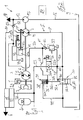
- FIG. 1 is a circuit diagram of a hydrostatic drive system 1 according to the invention and drive train of a vehicle, not shown, for example, designed as a truck or construction or agricultural machine mobile machine, shown in a schematic diagram.
- the drive system 1 comprises an internal combustion engine 2, for example a diesel engine, a traction drive 3 driven by the internal combustion engine 2 and a working hydraulic system 4 driven by the internal combustion engine 2.
- an internal combustion engine 2 for example a diesel engine
- a traction drive 3 driven by the internal combustion engine 2
- a working hydraulic system 4 driven by the internal combustion engine 2.
- the traction drive 3 is formed in the illustrated embodiment as a hydrostatic drive, which consists of a continuously variable in the delivery volume drive pump 5 as a primary unit, which is in drive connection to the drive with an output shaft 6 of the engine 2.
- the drive pump 5 is connected to one or more in the intake volume fixed or adjustable, not shown hydraulic motors as secondary units, in a closed circuit in combination, which are in a manner not shown in operative connection with the driven wheels of the vehicle.
- the traction drive 3 may alternatively be formed as an electric traction drive with a driven by the internal combustion engine 2 electric generator as the primary unit and one or more electric traction motors as secondary units.
- a mechanical traction drive with a mechanical transmission for example a stepped transmission or a power split transmission or a torque converter transmission can be provided as the drive.
- the working hydraulic system 4 includes working functions of the working machine, for example, in a truck, a working hydraulics for actuating a lifting device on a lifting mast, or in an example as an excavator or wheel loader-trained construction machine the working functions of working equipment trained by a shovel.
- the working hydraulic system 4 comprises to supply the working functions and thus the consumer with pressure means a hydrostatic engine 7.
- the engine 7 is operated in an open circuit and is for driving with the output shaft 6 of the engine 2 in drive connection.
- the engine 7 can be designed as constant-displacement engine in the displacement volume.
- the engine 7 is designed as an adjusting drive with a continuously variable displacement volume, for example as axial piston machine in swash plate design.
- the engine 7, which is operated in an open circuit, is connected on the inlet side to a suction connection by means of a suction line or a suction channel 8, which form a suction side S, with a container 9.
- An output side connected to the delivery port and the delivery side P of the engine 7 in connection conveyor line 10 is connected to a control valve device 11, by means of which the not shown hydraulic consumers of the working hydraulic system 4 are controllable.
- the control valve device 11 preferably comprises one or more directional control valves for actuating the consumers, which may also include a hydraulic steering device of the vehicle.
- the drive system 1 further comprises a feed pump 15, which is connected to the drive with the output shaft 6 in connection.
- the feed pump 15 is formed in the illustrated embodiment as a constant displacement pump with a constant displacement volume, which is operated in the open circuit.
- the feed pump 15 communicates with the suction side via a suction line 16 to the container 9 and conveys into a feed pressure line 17 connected to the feed ropes, to which the corresponding consumers of a feed pressure circuit 18 are connected, for example adjusting devices for adjusting the displacement volume of the drive pump 5 and 5 of the engine 7, a feeding device of the hydrostatic drive 3, a brake system of the vehicle and pilot valves for the control valves of the working hydraulic system 4.
- the feed pump 15 When the internal combustion engine 2, the feed pump 15 generates a constant feed pressure in the feed pressure circuit 18.
- a pressure limiting device such as a pressure relief valve assigned.
- the hydrostatic engine 7 of the working hydraulic system 4 is designed as Zwequadrantentriebwerk, which is operable at the same direction of rotation and the same flow direction of the pressure medium as a pump and motor.
- the engine 7 In pump operation, wherein the engine 7 is driven off by the running internal combustion engine 2, the engine 7 sucks pressure medium from the container 9 via the suction line 8 and delivers the pressure medium into the delivery line 10 for supplying the consumers of the working hydraulic system 4. Furthermore, the engine 7 is used in pump mode for loading a hydraulic accumulator 20 which can be connected via a charging valve 21 and a charging line 22 to the delivery line 10. For loading the accumulator 20 in this case the working in pump mode engine 7 can be driven either with the absorbed during deceleration of the vehicle kinetic energy of the vehicle or primary side of the current engine 2 driven.
- the engine 7 In engine operation of the engine 7, in which the engine 7 is designed as a hydraulic starter of a start-stop function for starting the engine 2, the engine 7 is driven on the suction side S with pressure medium from the accumulator 20.
- the connection of the accumulator 20 with the suction side S of the engine 7 for the engine operation of the engine 7 is controllable by means of an electrically actuated control valve 25.
- the control valve 25 has a blocking position 25a and a flow-through position 25b, wherein the blocking position 25a is preferably designed leakproof, with a blocking in the direction of the engine 7 check valve.
- the control valve 25 is designed as an electrically actuable control valve, preferably a switching valve, which can be actuated by means of an electrical actuating device 26, for example a solenoid, between the blocking position 25a and the flow position 25b.
- the actuating device 26 is connected to the control with an electronic control device 27 in connection.
- an electronic control device 27 For monitoring the accumulator charging pressure and thus the storage state of the pressure fluid accumulator 20, a pressure sensor device 28 connected to the control device 27 is provided.
- the electronic control device 27 is connected to a rotational speed sensor device 29 detecting the rotational speed of the internal combustion engine 2.
- the control device 27 can also control the charging valve 21 for the loading operation of the accumulator 20.
- the control valve 25 is arranged in a connecting line 23, which is guided by the accumulator 20 to the suction line 8 and connected to the suction line 8.
- a check valve device 30 is arranged between the connection of the connecting line 23 and the container 9, which allows a pressure build-up on the suction side S in engine operation of the engine 7.
- the check valve device 30 has an actuatable by means of an actuator 31 check valve 32.
- the check valve 32 is active between a in the FIG. 1 shown shut-off position 32a, in which the connection of the suction side S is shut off with the container 9 in the flow direction from the suction side S to the container 9, and one in the FIG. 1 shown in dashed lines open position 32b, in which the connection of the suction side S is open with the container 9.
- the engine 7 formed in the illustrated embodiment as an adjustment with a continuously variable displacement volume engine 7 has to adjust the displacer volume to a displacement volume adjusting device 40, for example, an inclination adjustable swash plate of an axial piston machine in swash plate design.
- the displacer volume adjusting device 40 comprises an actuating piston device 41 that is operatively connected to the displacer volume adjusting device 40 for actuation.
- the engine 7 according to the invention is designed as a unilaterally adjustable engine in which the displacer volume adjusting device 40 moves from a position with a minimum displacer volume in a setting direction or pivoting direction to a position Maximum displacer volume is adjustable.
- the actuating piston device 41 has an actuating pressure space 41 a acting in the direction of the maximum displacement volume and a control pressure space 41 b acting in the direction of the minimum displacement volume.
- the displacer volume adjusting device 40 can be actuated by means of an adjusting device 42.
- the adjusting device 42 has a control valve, not shown in detail, with which the loading of the control pressure chambers 41 a, 41 b of the control piston means 41 of the displacement volume adjusting device 40 with a control pressure or their discharge to the container 9 is controllable.
- the adjusting device 42 is connected to the supply pressure line 17 and thus the feed pressure circuit 18 for supplying pressure medium and for generating a setting pressure in the control pressure chambers 41 a and 41 b via a control pressure line 43. Furthermore, the adjusting device 42 has a connection to a container 9 guided to the container conduit 44. The adjusting device 42 is preferably electrically controllable and is for this purpose with the electronic control device 27 in connection. In the illustrated embodiment, the adjusting device 42 comprises a control valve, wherein a mechanical feedback and feedback 46 of the actual position of the displacement volume adjusting device 40 is provided on the adjusting device 42. Furthermore, a spring device 45 designed as a compression spring is provided, which acts on the displacement volume adjusting device 40 in the direction of the minimum displacement volume, which can be limited by a corresponding stop of the displacement volume adjusting device 40.
- the adjusting device 42 In order to pressurize the displacement volume adjusting device 40 in a start operation of the start-stop function of the parked internal combustion engine 2 by the engine operation of the engine 7 in the direction of the position with maximum displacement, the adjusting device 42 in addition to the supply of pressure medium and thus to generate a control pressure to the Pressure fluid accumulator 20 can be connected.
- a guided from the control pressure line 43 to the connecting line 23 pressure medium line 50 is provided.
- a pressure reducing valve 51 is arranged in the pressure medium line 50.
- the pressure medium line 50 is in this case connected between the control valve 25 and the suction line 8 to the connecting line 23.
- a check valve 52 is further arranged in the connection of the adjusting device 42 with the feed pressure circuit 18.
- the pressure medium line 50 is in this case connected between the check valve 52 and the adjusting device 42 to the control pressure line 43.
- the check valve 52 is formed in the illustrated embodiment as in the direction of the actuator 42 opening check valve 53.
- the inventive, arranged in the suction line 8 check valve 32 of the FIG. 1 is designed as a flap valve 33 with a pivotable about a pivot axis 35 flap 34.
- the flap 34 is operatively connected to the actuator 31 for operation.
- the actuator 31 of the check valve 32 is designed as a longitudinally displaceable actuating piston 36.
- the adjusting piston 36 has a piston rod 36 c, which is drivingly connected to the flap 34.
- the piston rod 36c of the actuating piston 36 with the intermediate position of a hinged to the flap 34 and hinged to the piston rod 36c of the actuating 36 articulated coupling rod 37, for example a rocker, with the flap 34 in operative connection.
- the adjusting piston 36 is arranged longitudinally displaceable in a cylinder housing, in which a control piston 36 in the direction of the illustrated shut-off 32a of the check valve 32 acting piston pressure chamber 36a and the adjusting piston 36 in the direction of the open position 32b of the check valve 32 acting piston pressure chamber 36b are formed.
- a control piston 36 in the direction of the illustrated shut-off 32a of the check valve 32 acting piston pressure chamber 36a and the adjusting piston 36 in the direction of the open position 32b of the check valve 32 acting piston pressure chamber 36b are formed in the piston pressure chamber 36a is arranged a control piston 36 and thus the check valve 32 in the shut-off position 32a acting spring means 38, for example a compression spring.
- the piston pressure chamber 36a provided with the spring device 38 is connected to the container 9 by means of a relief line 39.
- the non-return valve 32 can be actuated into the open position 32b by a hydraulic actuation pressure acting upon the actuation device 31.
- the actuating pressure of the constant feed pressure of the feed pressure circuit 18 is formed, including a branched off from the pressure medium line 50 and the control pressure line 43 branch line 60 to the acting in the opening direction piston pressure chamber 36b of the actuating piston 36th connected.
- a check valve 61 is arranged, which is formed in the illustrated embodiment as a blocking in the direction of the pressure reducing valve 51 check valve 62.
- the flap 34 of the flap valve 33 controls in the illustrated shut-off position 32a to a valve seat 65 which is formed in the suction line 8, which is formed for this purpose at least in the region of the valve seat 65 as a suction channel.
- the pivot axis 35 of the flap 34 is arranged in the radial direction outside the diameter D of the suction line 8, so that the flap 34 is not immersed in the open position 32b and thus the open switching position in the suction line 8 and in the open position 32b no additional hydraulic resistance and thus Flow resistance caused in the suction line 8.
- a radial extension 66 is formed on the suction line 8 designed as a suction channel into which the flap 34 preferably swings completely in the open position 32b.
- the check valve device 30 can be installed in the housing of the engine 7.
- the check valve device 30 has a separate housing 70, which forms a portion of the suction line 8.
- housing 70 of the check valve device 30 may further be the control valve 25 and the pressure reducing valve 51 are installed.
- the housing 70 can in this case preferably be flanged to the suction port of the engine 7 and thus grown. Alternatively, this housing 70 may be installed separately from the engine 7 at any point on the intake manifold 8 within the vehicle.
- the branch line 60 is the pressure generated at the pressure reducing valve 51 in the piston pressure chamber 36b of the actuating piston 36 and generates an acting in the direction of the open position of the flap 34 force on the control piston 36.
- the from the pressure of the accumulator 20 and thus the pressure in the suction line 8 force acting on the flap 34 in the direction of the shut-off position 32a outweighs the opening force on the adjusting piston 36, so that the flap 34 is held in the shut-off position 32a during the starting process of the internal combustion engine 2 and the engine operation of the engine 7.
- the engine 7 driven by the internal combustion engine 2 can be used to supply the load of the working hydraulic system 4 to the pump, wherein the flap 34 located in the open position 32b does not build up any additional hydraulic resistance in the suction line 8 and no flow resistances caused reduce the suction limit speed of the engine 7 in the pump mode.
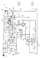
- FIG. 2 a second embodiment of the invention is shown.
- the same components are provided here with the same reference numerals.
- the FIG. 2 is different from the FIG. 1 with regard to the structural embodiment of the check valve 32 according to the invention.
- the check valve 32 of FIG. 2 is designed as a piston or flat slide valve 80 with a longitudinally displaceable piston or slide 81 which is operatively connected to the actuator 31 for actuation, which is analogous to the FIG. 1 is constructed.
- the piston or slide 81 can be actuated by means of the actuating device 31 by the actuating pressure formed as a feed pressure into the open position 32b and when the internal combustion engine 2 is switched off by means of the spring device 38 into the shut-off position 32a.
- the piston or slide 81 is arranged in the suction line 8 such that it does not form an additional flow resistance in the suction side S for the pressure medium drawn in by the engine 7 during pump operation in the open position 32b.
- the check valve 32 of the FIG. 2 be designed as a piston valve with a longitudinally displaceable and preferably cylindrical piston, which is operatively connected to the actuator 31 for actuation.
- the check valve may be formed as a ball valve.
- FIG. 3 a third embodiment of the invention is shown.
- the same components are provided here with the same reference numerals.
- the check valve 32 is analogous to FIG. 2 designed as a piston or flat slide valve 80 with a longitudinally displaceable piston or slide 81, which is operatively connected to the actuator 31, which is designed as acting in the direction of the open position 32b control pressure surface 105 on the check valve 32.
- the control pressure surface 105 For acting on the control pressure surface 105 with the feed pressure formed as the actuating pressure, the control pressure surface 105 is connected to the branch line 60.
- the check valve 32 is acted upon by the spring device 38.
- the further control pressure surface 100 acting in the direction of the shut-off position 32a is provided on the check valve 32, which communicates with the control pressure line 101 to the check valve 32 at a starting operation of the internal combustion engine 2 of the pressure of the pressure medium accumulator 20 and thus the pressure in the suction line 8th to keep in the shut-off position 32a and to avoid that the check valve 32 is operated before the end of the starting process of the internal combustion engine 2 from the generated feed pressure against the force of the spring means 38 in the open position 32b.
- control valve 25 breaks in the control pressure line 43 and the pressure medium line 50 connected thereto feed pressure together, which acts on the control pressure surface 105, so that the check valve 32 of the spring device 38th is acted upon in the shut-off position 32a.
- the control valve 25 is actuated at pressure fluid reservoir 20 charged with pressure medium in the flow position 25b, so that when in the shut-off position 32a check valve 32, the engine 2 can be started by the engine operation of the engine 7.
- control valve 25 is actuated in the blocking position 25a, so that the pending on the further control pressure surface 100, acting in the closing direction pressure of the accumulator 20 collapses.
- the feed pressure generated by the driven feed pump 15 is applied via the branch line 60 to the scattering pressure surface 105, whereby the check valve 32 is actuated by means of the control pressure surface 105 formed as actuator 31 in the open position 32 b.
- FIGS. 1 and 2 is the spring-side, acting in the blocking position 32a piston pressure chamber 36a of the actuating piston 36 relieved via the discharge line 39 to the container and acting in the open position 32b piston pressure chamber 36b of the actuating piston 36 via the branch line 60 with the actuating pressure formed as a feed pressure acted upon by the Engine operation of the engine 7 to achieve a hydraulic starter for a start-stop function of the parked internal combustion engine 2.
- FIG. 4 is a further education of FIG. 1 represented, wherein the same components are provided with the same reference numerals.
- a switching valve 90 is provided, by means of which the check valve 32 in response to the actuation pressure in the open position 32b is actuated in a first switching position 90a and by means of which in a second switching position 90b, the check valve 32 in the shut-off position 32a operable is.
- the switching valve 90 is provided for controlling the loading of the piston pressure chambers 36a, 36b of the adjusting piston 36, by means of which in a first switching position 90a acting in opening position 32b piston pressure chamber 36b of the actuating piston 36 is acted upon by the actuating pressure and the spring side, acting in the blocking position 32a piston pressure chamber 36a is relieved to the container 9 and in a second switching position 90b of the spring-side, acting in the blocking position 32a piston pressure chamber 36a of the actuating piston 36 is acted upon by the actuating pressure and acting in the open position 32b piston pressure chamber 36b is relieved to the container 9.
- the switching valve 90 is for this purpose with the operating pressure leading branch line 60, the discharge line 39 and the two piston pressure chambers 36a, 36b of the Stellkobens 36 in conjunction.
- the switching valve 90 is designed as a four-port two-position valve.
- the switching valve 90 is designed as an electrically actuable control valve, preferably switching valve, which can be actuated by means of an electrical actuating device 91, for example a switching magnet, between the switching positions 90a, 90b.
- an electrical actuating device 91 for example a switching magnet
- To control the change-over valve 90 is in operative connection with the electronic control device 27.
- the switching valve 90 is preferably installed in the housing 70.
- the switching position 90b of the reversing valve 90 allows the reverse control of the check valve 32 to output by the engine operation of the hydrostatic engine 7 with the internal combustion engine 2, an additional torque to the output shaft 6 of the engine 2 and to achieve a booster drive.
- the engine 2 With the booster drive through the hydrostatic engine 7, the engine 2 can be supported, for example, while driving the vehicle.
- the changeover valve 90 is actuated into the switching position 90b, so that the feed pressure generated by the driven feed pump 15 during running internal combustion engine 2 via the control pressure line 43, the pressure medium line 50 and the branch line 60 in the spring-side, in the direction of the shut-off position 32a the check valve 32 acting piston pressure chamber 36a of the actuating piston 36 is present. Since in the switching position 90b of the switching valve 90 acting in the opening position 32b piston pressure chamber 36b of the actuating piston 36 is relieved to the container 9, the check valve 32 can be actuated in the shut-off position 32a to the connection of the suction line 8 in the flow direction to the container 9th shut off.
- the control valve 25 in the flow position 25b thus the engine 7 can be driven with pressurized pressure medium from the accumulator 20 during engine operation to feed a torque in the drive train to support the current internal combustion engine 2.
- FIG. 4 In the FIG. 4 is in the shut-off position 32a of the check valve 32, a connection of the suction side S with the container 9 in the direction of flow from the container 9 to the suction side S during the booster drive allows, including in a check valve 32 bypassing the bypass line 96 of the suction line S in the direction of the engine. 7 opening check valve 95 is provided.
- the check valve 95 makes it possible for the booster drive to suck in pressure medium of the engine 7 driven by the running internal combustion engine 2 from the container 9 in the shut-off position 32b located check valve 32 before opening the control valve 25 in the flow position 25b for the engine operation of the engine. 7
- FIG. 5 is a further education of FIG. 3 shown, with the by the switching valve 90, a booster drive through the hydrostatic engine 7 is made possible to support the current internal combustion engine 2.
- the switching valve 90 communicates with the operating pressure leading branch line 60, the control line 101 connected to the connecting line 23 and the two control pressure surfaces 100, 105 in combination.
- the switching valve 90 is designed as a four-port two-position valve and electrically actuated by means of the electrical actuator 91.
- the control pressure surface 105 of the check valve 32 is connected to the branch line 60 and thus acted upon by the actuating pressure.
- the further control pressure surface 100 of the check valve 32 is connected in the first switching position 90a to the control pressure line 101 and thus connected to the suction side S between the engine 7 and the check valve 32.
- the above-described operation of the check valve 32 results according to the FIG. 3 for the use of the engine 7 in engine operation as a hydraulic starter in the context of a start-stop function of the internal combustion engine. 2
- the control pressure surface 105 and the further control pressure surface 100 of the check valves 32 are connected to the branch line 60 and thus acted upon by the actuating pressure.
- the control pressure line 101 is shut off in the second switching position 90b of the switching valve 90.
- the switching valve 90 is actuated in the switching position 90b, in which the check valve 32 is actuated in the shut-off position 32a and the connection of the suction line 8 is shut off in the flow direction to the container 9.
- the switching valve 25 in the flow position 25b can thus the Engine 7 are driven with pressure fluid under pressure from the accumulator 20 in engine operation to feed a torque in the drive train to support the current internal combustion engine 2.
- FIG. 6 shows a further development of FIG. 3 that differ from the FIG. 5 differs by the execution of the switching valve 90.
- the switching valve 90 of FIG. 6 is designed as a five-port two-position valve, which is electrically actuated by means of the electrical actuator 91.
- the switching valve 90 communicates with the operating pressure leading branch line 60, the connected to the connecting line 23 control pressure line 101, the two control pressure surfaces 100, 105 and guided to the container 9 relief line 39 in connection.
- the control pressure surface 105 of the check valve 32 is connected to the branch line 60 and thus acted upon by the actuating pressure.
- the further control pressure surface 100 of the check valve 32 is connected in the first switching position 90a to the control pressure line 101 and thus connected to the suction side S between the engine 7 and the check valve 32.
- the discharge line 39 is shut off.
- the above-described operation of the check valve 32 results according to the FIG. 3 for the use of the engine 7 in engine operation as a hydraulic starter in the context of a start-stop function of the internal combustion engine. 2
- the control pressure surface 105 is connected to the relief line 39 and the other control pressure surface 100 connected to the branch line 60 and thus acted upon by the actuating pressure.
- the control pressure line 101 is shut off.
- the switching valve 90 is actuated in the switching position 90 b, in which the check valve 32 is actuated in the shut-off position 32 a and the Connection of the suction line 8 is shut off in the flow direction to the container 9.
- the switching valve 25 By driving the switching valve 25 in the flow position 25b thus the engine 7 can be driven with pressurized pressure fluid from the accumulator 20 in engine operation to feed a torque in the drive train to support the current internal combustion engine 2.
- Both Figures 5 and 6 is in the shut-off position 32a of the check valve 32, a connection of the suction side S with the container 9 in the direction of flow from the container 9 to the suction side S during the booster drive allows, for which purpose in the shut-off position 32a in the direction of the engine 7 opening check valve 95 is provided.
- the actuating device 31 which is in the form of a control piston or control surface 105, is acted upon by the pressure of the pressure medium reservoir 20 provided by the feed pump 15 as the feed pressure in the direction of the open position 32b of the check valve 32 that when the internal combustion engine 2, the check valve 32 is actuated in the open position 32 b.
- the check valve 32 is actuated by the spring means 38 in the shut-off position 32a and held by the spring device 38 in the shut-off position 32a.
- the check valve 32 When the internal combustion engine 2 is turned off, the check valve 32 is thus automatically in the shut-off position 32a, so that in a start-stop function by controlling the Control valve 25 in the flow position 25b directly and directly a hydrostatic start of the engine 2 by the engine operation of the engine 7 can be carried out without having to press the check valve 32 in the shut-off position 32a before.
- the function of the check valve 32 in a start-stop function and use of the engine 7 as a hydraulic starter of the internal combustion engine 2 can thus be achieved without additional control logic and additional control valves for controlling the actuator 31.
- the control of the check valve 32 are switched in the function to operate with the internal combustion engine 2 by operating the check valve 32 in the shut-off position 32a by running as a constant feed pressure operating pressure motor operation of the engine 7 for outputting a torque to the output shaft 6 for to create a booster drive.
- the check valve 32 may be formed as a spool valve with a rotatable piston or ball valve with a rotatable ball, wherein the piston or the ball with the actuator 31 is in operative connection and by means of the actuating piston 36 and as a control pressure surface 105 formed actuator 31 active between a shut-off and an open position is rotated.
- the hydrostatic engine 7 may alternatively be designed as an axial piston machine as a gear machine, as a radial piston machine or any other common construction, each with a constant displacement volume or alternatively continuously variable displacement volume.
- the invention is not limited to the illustrated sequence of the arrangement of the traction drive 3, the hydrostatic engine 7 and the feed pump 15 on the output shaft 6 of the internal combustion engine 2, but their arrangement can be varied and changed as desired.
Abstract
Description
Die Erfindung betrifft eine Rückschlagventileinrichtung eines hydrostatischen Triebwerks, das mit einem Verbrennungsmotor trieblich verbunden ist und als Pumpe und Motor betreibbar ist, wobei das Triebwerk im Pumpenbetrieb mit einer Saugseite Druckmittel aus einem Behälter ansaugt und in Förderseite fördert und wobei das Triebwerk im Motorbetrieb von über die Saugseite, die mit dem Behälter in Verbindung steht, zugeführtem und unter Druck stehendem Druckmittel aus einem Druckmittelspeicher angetrieben ist, wobei die Rückschlagventileinrichtung in der Saugseite des hydrostatischen Triebwerks angeordnet ist, um im Motorbetrieb einen Druckaufbau an der Saugseite zu erzielen.The invention relates to a check valve device of a hydrostatic engine, which is drivingly connected to an internal combustion engine and is operable as a pump and motor, the engine sucks in pumping operation with a suction side pressure medium from a container and promotes delivery side and wherein the engine in the engine operation of the Suction side, which is in communication with the container, supplied and pressurized pressure fluid is driven from a pressure fluid reservoir, wherein the check valve device is arranged in the suction side of the hydrostatic engine to achieve a pressure build-up on the suction side in engine operation.
Mobile selbstfahrende Arbeitsmaschinen, insbesondere Flurförderzeuge, Landmaschinen, Forstmaschinen und Baumaschinen, beispielsweise Bagger, Rad- und Teleskoplader, Schlepper, Mähdrescher, Feldhäcksler, Zuckerrüben- oder Kartoffelroder, weisen einen Antriebsstrang mit einem Verbrennungsmotor auf, der einen Fahrantrieb und ein Arbeitshydrauliksystem für die Arbeitsfunktionen der Arbeitsmaschine antreibt. Zur Versorgung des Arbeitshydrauliksystems ist mindestens eine von dem Verbrennungsmotor angetriebene Hydraulikpumpe vorgesehen.Mobile self-propelled machines, especially industrial trucks, agricultural machinery, forestry machinery and construction equipment, such as excavators, wheeled and telescopic loaders, tractors, combine harvester, forage harvester, sugar beet or potato harvester, have a drive train with an internal combustion engine, a traction drive and a working hydraulic system for the working functions of Working machine drives. To supply the working hydraulic system at least one of the internal combustion engine driven hydraulic pump is provided.
Während eines Leerlaufbetriebs, in dem der Fahrantrieb und das Arbeitshydrauliksystem nicht betätigt sind und somit von dem Verbrennungsmotor keine Drehmomentanforderung angefordert wird, wird der Verbrennungsmotor auf einer unteren Leerlaufdrehzahl betrieben. Ein derartiger Leerlaufbetrieb findet in Arbeitspausen oder während Arbeitsunterbrechungen statt.During an idling operation in which the traction drive and the working hydraulic system are not actuated and thus no torque request is requested from the internal combustion engine, the internal combustion engine is operated at a lower idling speed. Such idling operation takes place during work breaks or during work stoppages.
Um den Kraftstoffverbrauch während Arbeitspausen oder Arbeitsunterbrechungen zu verringern, ist es bereits bekannt, eine sogenannte Start-Stopp-Funktion für den Verbrennungsmotor vorzusehen, bei der der unbelastete Verbrennungsmotor in Arbeitspausen oder bei Arbeitsunterbrechungen abgeschaltet wird und bei einer Drehmomentanforderung durch eine Arbeitsfunktion oder den Fahrantrieb automatisch wieder gestartet wird. Das Abschalten und der nachfolgende Neustart des Verbrennungsmotors erfolgt hierbei auch bei relativ kurzen Leerlaufzeiten, so dass der Startvorgang des Verbrennungsmotors entsprechend häufig im Betrieb der Arbeitsmaschine auftritt. Dies stellt hohe Anforderungen an die Startereinrichtung des Verbrennungsmotors hinsichtlich der Dauerfestigkeit und der Bereitstellung der erforderlichen Startenergie zum Starten des Verbrennungsmotors.In order to reduce fuel consumption during work breaks or work stoppages, it is already known to provide a so-called start-stop function for the internal combustion engine, in which the unloaded combustion engine is switched off during work breaks or work stoppages and automatically when a torque request by a work function or the traction drive is restarted. The shutdown and the subsequent restart of the engine takes place here even at relatively short idle times, so that the starting process of the engine occurs frequently in operation of the machine. This places high demands on the starter device of the internal combustion engine with regard to the fatigue strength and the provision of the required starting energy for starting the internal combustion engine.
Bei mobilen Arbeitsmaschinen werden daher hydrostatische Triebwerke als hydraulische Starter des Verbrennungsmotors für eine Start-Stopp-Funktion eingesetzt, die mit der Kurbelwelle des Verbrennungsmotors trieblich verbunden sind und mit Druckmittel aus einem vor dem Abstellen des Verbrennungsmotor aufgeladenen Druckmittelspeicher bei einem Startvorgang des Verbrennungsmotors betrieben werden. Aus der
Um den Aufwand für einen zusätzlichen Hydraulikmotor als hydraulischer Starter des Verbrennungsmotors zu vermeiden, ist es bei mobilen Arbeitsmaschinen mit einer Start-Stopp-Funktion bereits bekannt, die bereits vorhandene Hydraulikpumpe des Arbeitshydrauliksystems als hydraulischen Starter des Verbrennungsmotors zu nutzen, in dem die Hydraulikpumpe bei gleicher Drehrichtung und gleicher Flussrichtung des Druckmittels zusätzlich als Motor betrieben wird, der Druckmittel aus einem Druckmittelspeicher an der mit dem Behälter in Verbindung stehenden Saugseite zugeführt wird. Die Hydraulikpumpe des Arbeitshydrauliksystems ist in der Regel als eine im offenen Kreislauf betriebene Hydraulikpumpe ausgebildet, die mit einem Sauganschluss für das Druckmittel über eine Saugseite mit einem Behälter in Verbindung steht und das Druckmittel in eine an einen Förderanschluss angeschlossene Förderleitung fördert. Im Pumpenbetrieb, in dem die Hydraulikpumpe von dem laufenden Verbrennungsmotor angetrieben wird, saugt die Hydraulikpumpe Druckmittel über die Saugseite aus dem Behälter und fördert dieses zur Versorgung der Verbraucher des Arbeitshydrauliksystems in die Förderleitung. Sofern die Hydraulikpumpe an der Saugseite mit Druckmittel unter Druck aus einem Druckmittelspeicher beaufschlagt wird, arbeitet die Hydraulikpumpe bei gleicher Drehrichtung des hydrostatischen Triebwerks und gleicher Flussrichtung des Druckmittels als Motor, der es ermöglicht, an der Kurbelwelle des Verbrennungsmotors ein Drehmoment zum Starten des Verbrennungsmotors im Rahmen einer Start-Stopp-Funktion zu erzeugen und/oder bei laufendem Verbrennungsmotor ein Zusatzdrehmoment an die Kurbelwelle abzugeben, um den laufenden Verbrennungsmotor im Rahmen eines Booster-Antriebs zu entlasten und zu unterstützen.To avoid the expense of an additional hydraulic motor as a hydraulic starter of the engine, it is already known in mobile machines with a start-stop function to use the existing hydraulic pump of the working hydraulic system as a hydraulic starter of the engine, in which the hydraulic pump at the same Direction of rotation and the same flow direction of the pressure medium is additionally operated as a motor, the pressure medium is supplied from a pressure medium accumulator to the suction side connected to the container. As a rule, the hydraulic pump of the working hydraulic system is designed as a hydraulic pump operated in open circuit, which communicates with a suction connection for the pressure medium via a suction side with a container and conveys the pressure medium into a delivery line connected to a delivery connection. In pump operation, in which the hydraulic pump is driven by the running internal combustion engine, the hydraulic pump sucks Pressure medium via the suction side of the container and promotes this to supply the load of the working hydraulic system in the delivery line. If the hydraulic pump is pressurized on the suction side with pressure medium under pressure from a pressure medium reservoir, the hydraulic pump operates at the same direction of rotation of the hydrostatic engine and the same flow direction of the pressure medium as an engine, which allows, on the crankshaft of the internal combustion engine, a torque for starting the internal combustion engine in the frame To generate a start-stop function and / or deliver an additional torque to the crankshaft with the internal combustion engine to relieve the current engine in the context of a booster drive and support.
Der Booster-Antrieb durch den Motorbetrieb der Hydraulikpumpe des Arbeitshydrauliksystems bei laufendem Verbrennungsmotor ermöglicht es, den Kraftstoffverbrauch des Verbrennungsmotors zu senken. Zudem kann durch den hydrostatischen Booster-Antrieb der Verbrennungsmotor in seiner Leistung verringert werden. Ein derartiges Downsizing des Verbrennungsmotors führt insbesondere bei der Einhaltung von gesetzlichen Abgasvorschriften des Verbrennungsmotors zu Vorteilen.The booster drive by the engine operation of the hydraulic pump of the working hydraulic system with the engine running makes it possible to reduce the fuel consumption of the internal combustion engine. In addition, the combustion engine can be reduced in its power by the hydrostatic booster drive. Such a downsizing of the internal combustion engine leads to advantages, in particular in the observance of legal exhaust gas regulations of the internal combustion engine.
Um bei einem derartigen hydrostatischen Triebwerk, das bei gleicher Drehrichtung und gleicher Flussrichtung des Druckmittels als Pumpe und Motor betrieben wird, einen Motorbetrieb zu ermöglichen, ist es erforderlich, in der Saugseite des Triebwerks ein in Durchflussrichtung zum Behälter schließendes Rückschlagventil anzuordnen, das im Motorbetrieb geschlossen ist und dadurch einen Druckaufbau in der Saugseite ermöglicht und verhindert, dass das aus dem Druckmittelspeicher der Saugseite zugeführte Druckmittel zum Behälter abströmt.In order to allow for such a hydrostatic engine, which is operated at the same direction of rotation and the same flow direction of the pressure medium as a pump and motor, a motor operation, it is necessary to arrange in the suction side of the engine in the flow direction to the container closing check valve, which is closed during engine operation is and thereby allows a pressure build-up in the suction side and prevents that flows from the pressure fluid reservoir of the suction side pressure fluid flows to the container.
Aus den
Die Hydraulikpumpe, beispielsweise eine Axialkolbenmaschine, des Arbeitshydrauliksystems ist in der Regel auf eine hohe Sauggrenzdrehzahl für den Pumpenbetrieb ausgelegt. Die im Pumpenbetrieb mit dem Behälter verbundene Saugseite und der Sauganschluss des hydrostatischen Triebwerks weist hierbei einen entsprechend großen Querschnitt auf. Bei den
Der vorliegenden Erfindung liegt die Aufgabe zugrunde, eine in der Saugseite eines hydrostatischen Triebwerks, das bei gleicher Drehrichtung als Pumpe und Motor betreibbar ist, wobei dem Triebwerk im Motorbetrieb Druckmittel aus einem Druckmittelspeicher an der Saugseite zugeführt wird, angeordnete Rückschlagventileinrichtung zur Verfügung zu stellen, die im Pumpenbetrieb des Triebwerks bei geöffneter Rückschlagventileinrichtung die Sauggrenzdrehzahl des Triebwerks nicht beeinträchtigt.The present invention has for its object, in the suction side of a hydrostatic engine, which is operated in the same direction of rotation as a pump and motor, wherein the engine is supplied in engine operation pressure fluid from a pressure fluid reservoir on the suction side, arranged check valve device to provide the In pump operation of the engine with open check valve device, the Sauggrenzdrehzahl the engine is not affected.
Diese Aufgabe wird erfindungsgemäß dadurch gelöst, dass die Rückschlagventileinrichtung ein mittels einer Betätigungseinrichtung betätigbares Rückschlagventil aufweist, wobei mittels der Betätigungseinrichtung das Rückschlagventil aktiv zwischen einer Absperrstellung, in der eine Verbindung der Saugseite mit dem Behälter in Durchflussrichtung von der Saugseite zum Behälter absperrt ist, und einer Öffnungsstellung betätigbar ist, in der die Verbindung der Saugseite mit dem Behälter geöffnet ist. Ein mittels einer Betätigungseinrichtung aktiv zwischen einer Absperrstellung und einer Öffnungsstellung betätigbares Rückschlagventil weist gegenüber druckbetätigten Rückschlagventilen des Standes der Technik den Vorteil auf, dass das Rückschlagventil derart ausgeführt werden kann, dass das Rückschlagventil in der Öffnungsstellung keinen zusätzlichen hydraulischen Widerstand in der Saugseite darstellt und somit keinen zusätzlichen Strömungswiderstand in der Saugseite verursacht. Mit dem erfindungsgemäßen aktiv durch die Betätigungseinrichtung steuerbaren Rückschlagventil kann somit ein hydrostatisches Triebwerk, das im Pumpenbetrieb zur Versorgung eines Verbrauchers, beispielsweise eines Arbeitshydrauliksystem, dient, im Motorbetrieb als hydraulischer Starter des Verbrennungsmotors und/oder als Booster-Antrieb zur Unterstützung des Verbrennungsmotors eingesetzt werden, ohne im Pumpenbetrieb eine verringerte Sauggrenzdrehzahl aufzuweisen.This object is achieved in that the check valve device comprises an actuatable by means of an actuator check valve, wherein by means of the actuator, the check valve active between a shut-off, in which a connection of the suction side is shut off with the container in the flow direction from the suction side to the container, and a Open position is actuated, in which the connection of the suction side is open with the container. An active by means of an actuator between a shut-off and an open position operable check valve has over pressure-actuated check valves of the prior art has the advantage that the check valve can be designed such that the check valve in the open position is no additional hydraulic resistance in the suction side and thus no additional flow resistance in the suction side caused. With the check valve according to the invention, which can be controlled actively by the actuating device, a hydrostatic engine which serves to supply a consumer, for example a working hydraulic system, can be used during engine operation as a hydraulic starter of the internal combustion engine and / or as a booster drive to assist the internal combustion engine. without having a reduced suction limit speed during pump operation.
Gemäß einer bevorzugten Ausgestaltungsform der Erfindung ist das Rückschlagventil mittels der Betätigungseinrichtung im Pumpenbetrieb des Triebwerks in die Öffnungsstellung und im Motorbetrieb des Triebwerks in die Absperrstellung betätigbar. Mit der Betätigungseinrichtung wird es auf einfache Weise ermöglicht, das Rückschlagventil im Pumpenbetrieb aktiv in die Öffnungsstellung aufzusteuern, um einen Pumpenbetrieb des hydrostatischen Triebwerks ohne zusätzliche Strömungswiderstände in der Saugseite zu erzielen, und das Rückschlagventil für den Motorbetrieb des hydrostatischen Triebwerks aktiv in die Absperrstellung zu betätigen, um einen Antrieb des Triebwerks über das aus dem Druckmittelspeicher der Saugseite zugeführten Druckmittel zu ermöglichen.According to a preferred embodiment of the invention, the check valve by means of the actuator in the pump operation of the engine in the open position and in engine operation of the engine in the shut-off position is actuated. With the actuator, it is easily possible to actively control the check valve to the open position during pump operation to achieve pump operation of the hydrostatic engine without additional flow resistances in the suction side and to actively actuate the hydrostatic engine check valve to the shut-off position to allow a drive of the engine via the supplied from the pressure medium accumulator suction side pressure medium.
Besondere Vorteile ergeben sich, wenn gemäß einer Ausgestaltungsform der Erfindung das Rückschlagventil mittels einer Federeinrichtung in die Absperrstellung betätigbar ist und das Rückschlagventil durch einen die Betätigungseinrichtung beaufschlagenden hydraulischen Betätigungsdruck in die Öffnungsstellung betätigbar ist. Mit einer derartigen hydrostatischen Steuerung der Betätigungseinrichtung und somit des Rückschlagventils kann eine einfache Steuerung und Betätigung des Rückschlagventils erzielt werden. Insbesondere werden weitere Vorteile erzielt, wenn der Betätigungsdruck lediglich bei laufendem Verbrennungsmotor erzeugt wird. Bei abgestelltem Verbrennungsmotor und nicht vorhandenem Betätigungsdruck wird somit das Rückschlagventil von der Federeinrichtung in die Absperrstellung betätigt, so dass bei der Verwendung des hydrostatischen Triebwerks als hydraulischer Starter des Verbrennungsmotor bei einem Startvorgang des Verbrennungsmotor unmittelbar der Motorbetrieb des Triebwerks erfolgen kann, ohne ein zeitlich vorheriges Betätigung des Rückschlagventils in die Absperrstellung durchführen zu müssen.Particular advantages arise when, according to one embodiment of the invention, the check valve by means of a spring device in the shut-off position is actuated and the check valve is actuated by an actuating device acting hydraulic actuating pressure in the open position. With such a hydrostatic control of the actuator and thus of the check valve, a simple control and operation of the check valve can be achieved. In particular, further advantages are achieved if the actuation pressure is generated only when the internal combustion engine is running. When the internal combustion engine and non-existent actuating pressure thus the check valve is actuated by the spring means in the shut-off, so that when using the hydrostatic engine as a hydraulic starter of the Internal combustion engine at a starting operation of the engine directly engine operation of the engine can be done without having to perform a timely operation of the check valve in the shut-off.
Gemäß einer bevorzugten Ausführungsform der Erfindung ist das in der Absperrstellung befindliche Rückschlagventil von dem in der Saugseite anstehenden Druck des Druckmittelspeichers in die Absperrstellung beaufschlagt. Hierdurch wird erzielt, dass das Rückschlagventil während der Dauer des Startvorgangs des Verbrennungsmotor von dem in der Saugseite anstehenden Druck des Druckmittelspeichers in der Absperrstellung gehalten wird und somit vermieden, dass das Rückschlagventil vor Ende des Startvorgangs von dem bei laufendem Verbrennungsmotor erzeugten Betätigungsdruck in die Öffnungsstellung betätigt wird.According to a preferred embodiment of the invention, the non-return valve located in the shut-off position is acted upon by the pending in the suction side pressure of the accumulator in the shut-off. This ensures that the check valve is held during the duration of the starting process of the internal combustion engine of the pending pressure in the suction side of the accumulator in the shut-off position and thus prevents the check valve operated before the end of the starting process of the operating pressure generated during operation of the internal combustion engine in the open position becomes.
Gemäß einer bevorzugten Ausgestaltungsform der Erfindung ist die Betätigungseinrichtung als mit dem Rückschlagventil in Wirkverbindung stehender Stellkolben ausgebildet. Mit einem Stellkolben kann auf einfache Weise eine aktive Betätigung des Rückschlagventils zwischen der Absperrstellung und der Öffnungsstellung erzielt werden.According to a preferred embodiment of the invention, the actuating device is designed as a standing with the check valve operatively connected actuating piston. With an actuating piston, an active actuation of the check valve between the shut-off position and the open position can be achieved in a simple manner.
Der Stellkolben ist gemäß einer zweckmäßigen Ausführungsform der Erfindung von der Federeinrichtung beaufschlagt und weist einen mit dem Betätigungsdruck beaufschlagbaren Kolbendruckraum auf, der der Federeinrichtung entgegenwirkt. Hierdurch kann mit geringem Bauaufwand erzielt werden, dass das Rückschlagventil von der Federeinrichtung in die Absperrstellung und mittels des Betätigungsdrucks in die Öffnungsstellung betätigt wird.The actuating piston is acted upon according to an expedient embodiment of the invention by the spring device and has a loadable with the actuating pressure piston pressure chamber, which counteracts the spring means. This can be achieved with low construction costs, that the check valve is actuated by the spring means in the shut-off position and by means of the actuating pressure in the open position.
Zweckmäßigerweise ist die Federeinrichtung in einem federseitigen Kolbendruckraum des Stellkolbens angeordnet, der mit dem Behälter verbindbar ist. Bei anstehendem Betätigungsdruck kann somit der Stellkolben entgegen der Kraft der Federeinrichtung bewegt werden und dadurch das Rückschlagventil in die Öffnungsstellung betätigt werden.Conveniently, the spring device is arranged in a spring-side piston pressure chamber of the actuating piston, which is connectable to the container. With pending actuation pressure thus the actuating piston can be moved against the force of the spring means and thereby the check valve can be actuated in the open position.
Gemäß einer alternativen Ausgestaltungsform der Erfindung ist die Betätigungseinrichtung als an dem Rückschlagventil angeordnete, von dem hydraulischen Betätigungsdruck beaufschlagbare Steuerdruckfläche ausgebildet, die das Rückschlagventil in Richtung der Öffnungsstellung betätigt. Mit einer derartigen Steuerdruckfläche an dem Rückschlagventil kann auf einfache Weise eine aktive Betätigung des Rückschlagventils zwischen der Absperrstellung und der Öffnungsstellung erzielt werden und mit geringem Bauaufwand erzielt werden, dass das Rückschlagventil von der Federeinrichtungen in die Absperrstellung und mittels des Betätigungsdrucks in die Öffnungsstellung betätigt wird.According to an alternative embodiment of the invention, the actuator is designed as arranged on the check valve, acted upon by the hydraulic actuating pressure control pressure surface, the the check valve is actuated in the direction of the open position. With such a control pressure surface on the check valve can be achieved in a simple manner active actuation of the check valve between the shut-off and the open position and are achieved with low construction costs, that the check valve is actuated by the spring means in the shut-off position and by means of the actuating pressure in the open position.
Gemäß einer vorteilhaften Ausführungsform der Erfindung ist das Rückschlagventil als Klappenventil mit einer verschwenkbaren Klappe ausgebildet, die mit der Betätigungseinrichtung in Wirkverbindung steht. Ein derartiges Klappenventil ermöglicht eine kompakte und platzsparende Bauweise des Rückschlagventils und kann mit geringem Bauaufwand mit einer als Stellkolben ausgebildeten Betätigungsrichtung betätigt werden. Bei einem Klappenventil wird zudem auf einfache Weise erzielt, dass das in der Absperrstellung befindliche Klappenventil bei einem Startvorgang des Verbrennungsmotors von dem an der Saugseite des Triebwerks anstehenden Druck des Druckmittelspeichers in der Absperrstellung gehalten wird.According to an advantageous embodiment of the invention, the check valve is designed as a flap valve with a pivotable flap, which is in operative connection with the actuating device. Such a flap valve allows a compact and space-saving design of the check valve and can be operated with low construction costs with a trained as a control piston actuation direction. In a flap valve is also achieved in a simple manner that the flap valve located in the shut-off position is held in a starting operation of the internal combustion engine of the pending on the suction side of the engine pressure of the accumulator in the shut-off position.
Hierzu kann gemäß einer Ausgestaltungsform der Erfindung der Stellkolben unter Zwischenschaltung einer gelenkig an der Klappe und an dem Stellkoben angelenkten Koppelstange, insbesondere einer Schwinge, mit der Klappe in Wirkverbindung stehen. Mit einer gelenkig angelenkten Koppelstange kann auf einfache Weise durch die lineare Bewegung des Stellkolbens die verschwenkbare Klappe des Klappenventils betätigt werden.For this purpose, according to an embodiment of the invention, the adjusting piston with the interposition of a hinged on the flap and on the Stellkoben hinged coupling rod, in particular a rocker, are in operative connection with the flap. With a hinged coupling rod can be easily actuated by the linear movement of the actuating piston, the pivotable flap of the flap valve.
Alternativ zu einer zwischengeschalteten Koppelstange kann gemäß einer weiteren Ausgestaltungsform der Erfindung der Stellkolben direkt mit der Klappe gelenkig verbunden sein, wobei die Gelenkverbindung ein Langloch umfasst. Sofern die Gelenkverbindung zwischen dem Stellkolben und der schwenkbaren Klappe ein Langloch umfasst, kann ebenfalls auf einfache Weise durch lineare Bewegung des Stellkolbens die verschwenkbare Klappe des Klappenventils betätigt werden.As an alternative to an intermediate coupling rod, according to a further embodiment of the invention, the actuating piston can be connected directly to the flap in an articulated manner, wherein the articulated connection comprises a slot. If the articulated connection between the actuating piston and the pivotable flap comprises a slot, the pivotable flap of the flap valve can also be actuated in a simple manner by linear movement of the actuating piston.
Besondere Vorteile ergeben sich, wenn gemäß einer Ausführungsform der Erfindung die Klappe derart in einem Saugkanal schwenkbar angeordnet ist, dass die Klappe in der Öffnungsstellung nicht in den Saugkanal eintaucht. Hierdurch wird erzielt, dass die in der Öffnungsstellung befindliche Klappe keinen zusätzlichen hydraulischen Widerstand und somit keine zusätzlichen Strömungswiderstände in der Saugseite des Triebwerks während des Pumpenbetriebs verursacht.Particular advantages are obtained if, according to one embodiment of the invention, the flap is pivotably arranged in a suction channel in such a way that the flap does not dive into the suction channel in the open position. This ensures that the flap located in the open position no additional hydraulic Resistance and thus no additional flow resistance caused in the suction side of the engine during pump operation.
Gemäß einer alternativen Ausführungsform der Erfindung ist das Rückschlagventil als Flachschieberventil mit einem längsverschiebbaren Schieber ausgebildet, der mit der Betätigungseinrichtung in Wirkverbindung steht. Ein derartiges Flachschieberventil ermöglicht ebenfalls eine kompakte und platzsparende Bauweise des Rückschlagventils und kann mit geringem Bauaufwand mit einer als Stellkolben oder als Steuerdruckfläche ausgebildeten Betätigungsrichtung betätigt werden. Zudem kann bei einem Flachschieberventil auf einfache Weise erzielt werden, dass der Schieber in der Öffnungsstellung keine zusätzlichen Strömungswiderstände in der Saugseite des Triebwerks während des Pumpenbetriebs verursacht.According to an alternative embodiment of the invention, the check valve is designed as a flat slide valve with a longitudinally displaceable slider, which is in operative connection with the actuating device. Such a flat slide valve also allows a compact and space-saving design of the check valve and can be operated with low construction costs with a trained as a control piston or as a control pressure surface actuation direction. In addition, in a flat slide valve can be achieved in a simple manner that the slide in the open position causes no additional flow resistance in the suction side of the engine during pump operation.
Gemäß einer weiteren alternativen Ausführungsform der Erfindung ist das Rückschlagventil als Kolbenschieberventil mit einem längsverschiebbaren oder verdrehbaren Kolben ausgebildet, der mit der Betätigungseinrichtung in Wirkverbindung steht. Ein derartiges Kolbenschieberventil ermöglicht ebenfalls eine kompakte und platzsparende Bauweise des Rückschlagventils und kann mit geringem Bauaufwand mit einer als Stellkolben oder als Steuerdruckfläche ausgebildeten Betätigungsrichtung betätigt werden. Zudem kann bei einem Kolbenschieberventil auf einfache Weise erzielt werden, dass der bevorzugt zylindrische Kolben in der Öffnungsstellung keine zusätzlichen Strömungswiderstände in der Saugseite des Triebwerks während des Pumpenbetriebs verursacht.According to a further alternative embodiment of the invention, the check valve is designed as a piston slide valve with a longitudinally displaceable or rotatable piston, which is in operative connection with the actuating device. Such a piston valve also allows a compact and space-saving design of the check valve and can be operated with low construction costs with a trained as a control piston or as a control pressure surface actuation direction. In addition, it can be achieved in a piston valve in a simple manner that the preferably cylindrical piston in the open position causes no additional flow resistance in the suction side of the engine during pump operation.
Alternativ kann das Rückschlagventil als Kugelhahn mit einer verdrehbaren Kugel ausgebildet ist, die mit der Betätigungseinrichtung in Wirkverbindung steht. Ein Kugelhahn ermöglicht ebenfalls eine kompakte und platzsparende Bauweise des Rückschlagventils und kann mit geringem Bauaufwand mit einer als Stellkolben oder als Steuerdruckfläche ausgebildeten Betätigungsrichtung betätigt werden. Zudem kann bei einem Kugelhahn auf einfache Weise erzielt werden, dass die Kugel in der Öffnungsstellung keine zusätzlichen Strömungswiderstände in der Saugseite des Triebwerks während des Pumpenbetriebs verursacht.Alternatively, the check valve is designed as a ball valve with a rotatable ball, which is in operative connection with the actuating device. A ball valve also allows a compact and space-saving design of the check valve and can be operated with low construction costs with a trained as a control piston or as a control pressure surface actuation direction. In addition, it can be achieved in a ball valve in a simple manner that the ball in the open position causes no additional flow resistance in the suction side of the engine during pump operation.
Die Erfindung betrifft weiterhin ein hydrostatisches Triebwerk, das mit einem Verbrennungsmotor trieblich verbunden ist und als Pumpe und Motor betreibbar ist, wobei das Triebwerk im Pumpenbetrieb mit einer Saugseite Druckmittel aus einem Behälter ansaugt und in Förderseite fördert und wobei das Triebwerk im Motorbetrieb von über die Saugseite, die mit dem Behälter in Verbindung steht, zugeführtem und unter Druck stehendem Druckmittel aus einem Druckmittelspeicher angetrieben ist, wobei eine erfindungsgemäße Rückschlagventileinrichtung in der Saugseite des hydrostatischen Triebwerks angeordnet ist. Mit einer erfindungsgemäßen, in der Saugseite des Triebwerks angeordneten Rückschlagventileinrichtung, die aktiv mit der Betätigungseinrichtung zwischen der Absperrstellung und der Öffnungsstellung betätigbar ist, kann mit geringem Zusatzaufwand ein Motorbetrieb des Triebwerks erzielt werden, um das Triebwerk als hydraulischen Starter des Verbrennungsmotor bei einer Start-Stopp-Funktion und/oder als Booster-Antrieb zur Unterstützung des laufenden Verbrennungsmotors einzusetzen.The invention further relates to a hydrostatic engine, which is drivingly connected to an internal combustion engine and is operable as a pump and a motor, wherein the engine in pump mode with a suction side sucks pressure medium from a container and promotes delivery side and wherein the engine is driven in engine operation of the suction side, which communicates with the container, supplied and under pressure pressure medium from a pressure fluid reservoir, wherein a Check valve device according to the invention is arranged in the suction side of the hydrostatic engine. With an inventive, arranged in the suction side of the engine check valve means which is operable with the actuator between the shut-off and the open position, with little additional effort, a motor operation of the engine can be achieved to the engine as a hydraulic starter of the engine at a start-stop Function and / or as a booster drive to support the running internal combustion engine.
Die Saugseite des hydrostatischen Triebwerks kann hierbei als Saugkanal oder Saugleitung ausgebildet sein.The suction side of the hydrostatic engine can be designed here as a suction or suction line.
Gemäß einer Ausgestaltungsform der Erfindung ist die Rückschlagventileinrichtung in ein Gehäuse des Triebwerks eingebaut. Die Rückschlagventileinrichtung kann hierdurch mit geringem baulichen Aufwand in das Gehäuse des Triebwerks integriert werden und in dem im Gehäuse ausgebildeten Abschnitt des Saugkanals angeordnet werden.According to one embodiment of the invention, the check valve device is installed in a housing of the engine. The check valve device can thereby be integrated with little structural effort in the housing of the engine and are arranged in the housing formed in the portion of the suction channel.
Alternativ kann die Rückschlagventileinrichtung ein eigenständiges Gehäuse aufweisen. Hierdurch wird es auf einfache Weise ermöglicht, bei einem vorhandenen Triebwerk die erfindungsgemäße Rückschlagventileinrichtung zu ergänzen, um den zusätzlichen Motorbetrieb des Triebwerks für die Funktion des hydraulischen Starters und/oder die Funktion des Booster-Antriebs zu erzielen.Alternatively, the check valve device may have an independent housing. This makes it possible in a simple manner to supplement the inventive check valve device in an existing engine to achieve the additional engine operation of the engine for the function of the hydraulic starter and / or the function of the booster drive.
Das Gehäuse der Rückschlagventileinrichtung kann hierbei an das Gehäuse des Triebwerks angeflanscht werden. Sofern das Gehäuse der Rückschlagventileinrichtung derart ausgeführt ist, dass es an das Gehäuses des Triebwerks im Bereich des Sauganschlusses angeflanscht werden kann, kann mit geringem zusätzlichen Bauaufwand ein bereits vorhandenes Triebwerk mit der erfindungsgemäßen Rückschlagventileinrichtung versehen werden, um den zusätzlichen Motorbetrieb des Triebwerks für die Funktion des hydraulischen Starters und/oder die Funktion des Booster-Antriebs zu erzielen.The housing of the check valve device can in this case be flanged to the housing of the engine. If the housing of the check valve device is designed such that it can be flanged to the housing of the engine in the region of the suction port, with little additional construction costs, an existing engine with the check valve device according to the invention can be provided to the additional engine operation of Engine for the function of the hydraulic starter and / or to achieve the function of the booster drive.
Sofern zur Steuerung der Verbindung des Druckmittelspeichers mit der Saugseite des Triebwerks für den Motorbetrieb ein Steuerventil vorgesehen ist, kann auf einfache Weise die Saugseite des Triebwerks im Motorbetrieb mit dem Druckmittelspeicher verbunden werden.If a control valve is provided to control the connection of the accumulator with the suction side of the engine for engine operation, the suction side of the engine can be easily connected in engine operation with the accumulator.
Das Triebwerk kann als im Verdrängervolumen konstantes Konstanttriebwerk ausgebildet.The engine can be designed as a constant displacement engine in the displacement volume.
Alternativ kann das Triebwerk als im Verdrängervolumen verstellbareres Verstelltriebwerk ausgebildet sein, wobei das Verdrängervolumen mittels einer Verdrängervolumenstelleinrichtung einstellbar ist, die mittels einer Stelleinrichtung betätigbar ist, wobei die Stelleinrichtung zur Versorgung mit Druckmittel an einen Speisedruckkreis angeschlossen und mit dem Druckmittelspeicher verbindbar ist. Eine hydraulische bzw. elektro-hydraulische Stelleinrichtung kann durch die Verbindung mit einem Speisedruckkreis und/oder dem Druckmittelspeicher auf einfache Weise mit Druckmittel zur Verstellung und Betätigung der Verdrängervolumenstelleinrichtung versorgt werden. Die Verbindung der Stelleinrichtung mit dem Druckmittelspeicher ermöglicht es auf einfache Weise, dass im Motorbetrieb des als hydraulischen Starter verwendeten Triebwerks die Verdrängervolumenstelleinrichtung des Triebwerks für den Startvorgang des abgestellten Verbrennungsmotors in Richtung des maximalem Verdrängervolumens mit Druckmittel aus dem geladenen Druckmittelspeicher verstellt werden kann, um durch das aus dem Druckmittelspeicher der Saugseite zuströmenden Druckmittels ein entsprechendes Drehmoment zum Starten des Verbrennungsmotors erzeugen zu können.Alternatively, the engine can be designed as an adjusting drive that is more adjustable in the displacer volume, wherein the displacer volume can be adjusted by means of a displacer volume adjusting device which can be actuated by means of an adjusting device, wherein the adjusting device is connected to a feed pressure circuit for supplying pressurized fluid and can be connected to the accumulator. A hydraulic or electro-hydraulic adjusting device can be supplied by the connection with a feed pressure circuit and / or the pressure medium storage in a simple manner with pressure means for adjusting and actuating the displacement volume adjusting device. The connection of the adjusting device with the accumulator allows in a simple manner that the engine displacement control of the engine for the starting process of the parked internal combustion engine in the direction of the maximum displacement volume can be adjusted with pressure fluid from the charged pressure fluid reservoir in the engine operation of the engine used as a hydraulic starter by the to generate a corresponding torque for starting the internal combustion engine from the pressure fluid reservoir of the suction side inflowing pressure medium.
Mit besonderem Vorteil ist hierzu in der Verbindung der Stelleinrichtung mit dem Speisedruckkreis ein Sperrventil, insbesondere ein in Richtung zum Speisedruckkreis sperrendes Rückschlagventil, angeordnet. Mit einem derartigen Rückschlagventil kann auf einfache Weise bei einem Startvorgang des abgestelltem Verbrennungsmotors erzielt werden, dass lediglich die Stelleinrichtung des Triebwerks von dem Druckmittelspeicher mit Druckmittel versorgt wird und die weiteren Verbraucher des Speisedruckkreis von dem Druckmittelspeicher abgetrennt sind, so dass das in dem Druckmittelspeicher vorhandene Druckmittel in effektiver Weise für den Motorbetrieb des Triebwerks zur Verfügung steht.With particular advantage, this is in the connection of the adjusting device with the feed pressure circuit a check valve, in particular a blocking in the direction of the feed pressure circuit check valve arranged. With such a check valve can be easily achieved at a startup of the parked engine that only the actuator of the engine is supplied by the accumulator with pressure medium and the other consumers of the feed pressure circuit are separated from the accumulator, so that in the Pressure fluid accumulator existing pressure fluid is available in an effective manner for the engine operation of the engine.
Hierzu steht zweckmäßigerweise der Druckmittelspeicher mit der Saugseite des Triebwerks mittels einer Verbindungsleitung in Verbindung, in der das Steuerventil angeordnet ist, wobei zur Versorgung der Stelleinrichtung mit Druckmittel aus dem Druckmittelspeicher eine Druckmittelleitung vorgesehen ist, die zwischen dem Steuerventil und der Saugseite des Triebwerks an die Verbindungsleitung angeschlossen ist. Durch einen derartigen Anschluss der die Stelleinrichtung mit Druckmittel aus dem Druckmittelspeicher versorgenden Druckmittelleitung wird auf einfache Weise erzielt, dass bei einer entsprechenden Betätigung des Steuerventils in eine Durchflussstellung für den Motorbetrieb des Triebwerks bei einem Startvorgang des Verbrennungsmotors die Stelleinrichtung der Verdrängervolumenstelleinrichtung des Triebwerks ebenfalls mit Druckmittel versorgt wird, um ein Verstellen der Verdrängervolumenstelleinrichtung des Triebwerks in Richtung des maximalem Verdrängervolumens zu erzielen.For this purpose, the pressure fluid accumulator is expediently connected to the intake side of the engine by means of a connecting line in which the control valve is arranged, wherein a pressure medium line is provided for supplying the actuating device with pressure medium from the pressure fluid accumulator, which between the control valve and the suction side of the engine to the connecting line connected. By such a connection of the adjusting device with pressure medium from the pressure fluid reservoir supplying pressure medium line is achieved in a simple manner that, with a corresponding actuation of the control valve in a flow position for the engine operation of the engine at a starting operation of the engine, the actuator of the displacement volume control device of the engine also supplied with pressure medium in order to achieve an adjustment of the displacement volume adjusting device of the engine in the direction of the maximum displacement volume.
Mit besonderem Vorteil ist die Druckmittelleitung an eine von dem Speisedruckkreis zu der Stelleinrichtung geführte Stelldruckleitung angeschlossen, in der das Sperrventil angeordnet ist, wobei die Druckmittelleitung zwischen dem Sperrventil und der Stelleinrichtung an die Stelldruckleitung angeschlossen ist. Mit einem derartigen Anschluss der Druckmittelleitung an die mit dem Sperrventil versehene Stelldruckleitung wird auf einfache Weise erzielt, dass bei einem Startvorgang des Verbrennungsmotors lediglich die Stelleinrichtung des Triebwerks mit Druckmittel aus dem Druckmittelspeicher versorgt wird.With particular advantage, the pressure medium line is connected to a guided from the feed pressure circuit to the actuating device actuating pressure line in which the check valve is arranged, wherein the pressure medium line between the check valve and the adjusting device is connected to the control pressure line. With such a connection of the pressure medium line to the control valve provided with the actuating pressure line is achieved in a simple manner that when a starting process of the internal combustion engine, only the actuator of the engine is supplied with pressure medium from the accumulator.
Zweckmäßigerweise ist in der Druckmittelleitung ein Druckminderventil angeordnet, wodurch mit geringem zusätzlichen Bauaufwand das in dem Druckmittelspeicher vorhandene Druckniveau auf das Niveau des Speisedrucks zur Versorgung der Stelleinrichtung des Triebwerks herabgesetzt werden kann.Conveniently, a pressure reducing valve is arranged in the pressure medium line, whereby the pressure level existing in the accumulator memory can be reduced to the level of the feed pressure for supplying the adjusting device of the engine with little additional construction costs.
Mit besonderem Vorteil ist der Speisedruck eines Speisedruckkreises als Betätigungsdruck der Betätigungseinrichtung des Rückschlagventils ausgebildet. Hierdurch kann auf einfache Weise und mit geringem Bauaufwand eine hydrostatische Betätigung der Betätigungseinrichtung und somit des Rückschlagventils erzielt werden. Hierzu ist zweckmäßigerweise eine von der Druckmittelleitung zu der Betätigungseinrichtung geführte Zweigleitung vorgesehen, wobei zwischen dem Druckminderventil und dem Anschluss der Zweigleitung ein Sperrventil, insbesondere ein in Richtung zum Druckminderventil sperrendes Rückschlagventil, angeordnet ist. Mit einer derartigen, von der Druckmittelleitung abzweigenden Zweigleitung wird erzielt, dass bei einem Startvorgang der über das Druckminderventil erzeugte Speisedruck in der Zweigleitung ansteht und nach dem Startvorgang bei laufendem Verbrennungsmotor der Speisedruck des Speisedruckkreises die Betätigungseinrichtung beaufschlagt, um das Rückschlagventil im Pumpenbetrieb in die Öffnungsstellung zu betätigen und in der Öffnungsstellung zu halten.With particular advantage, the feed pressure of a feed pressure circuit is formed as the actuating pressure of the actuating device of the check valve. As a result, a hydrostatic actuation of the actuating device and thus of the check valve can be achieved in a simple manner and with low construction costs. For this purpose, a guided from the pressure medium line to the actuator branch line is expediently provided, wherein between the pressure reducing valve and the connection of the branch line a check valve, in particular a blocking in the direction of the pressure reducing valve check valve is arranged. With such, branched off from the pressure medium line branch line is achieved that is present at a starting operation of the pressure reduction valve generated feed pressure in the branch line and after the starting process with the engine running the feed pressure of the feed pressure circuit actuates the actuator to the check valve in pump operation in the open position Press and hold in the open position.
Gemäß einer Ausgestaltungsform der Erfindung ist der Kolbendruckraum des Stellkolbens mit dem Speisedruckkreis verbunden und ist der federseitige Kolbendruckraum des Stellkolbens zu dem Behälter entlastet. Mit einem derartigen Anschluss des Stellkolbens wird ohne zusätzliche Steuerventile und einer Steuerlogik eine Funktionalität des Rückschlagventils für die Verwendung des Triebwerks im Motorbetrieb als hydraulischen Starter des Verbrennungsmotors erzielt, bei der das Rückschlagventil bei abgestelltem Verbrennungsmotor mittels der Federeinrichtung in die Absperrstellung betätigt ist und bei laufendem Verbrennungsmotor von dem erzeugten Speisedruck des Speisedruckkreises in die Öffnungsstellung betätigt ist.According to one embodiment of the invention, the piston pressure chamber of the actuating piston is connected to the feed pressure circuit and the spring-side piston pressure chamber of the actuating piston is relieved to the container. With such a connection of the actuating piston is achieved without additional control valves and a control logic functionality of the check valve for the use of the engine during engine operation as a hydraulic starter of the engine, wherein the check valve is actuated with the engine off by means of the spring device in the shut-off and running engine is actuated by the generated feed pressure of the feed pressure circuit in the open position.
Gemäß einer alternativen Ausgestaltungsform der Erfindung ist die Steuerdruckfläche des Rückschlagventils mit dem Speisedruckkreis verbunden und ist eine weitere Steuerdruckfläche an dem Rückschlagventil ausgebildet, die das Rückschlagventil in Richtung der Absperrstellung betätigt, wobei die weitere Steuerdruckfläche zur Druckbeaufschlagung mit der Saugseite zwischen dem Triebwerk und dem Rückschlagventil verbindbar ist. Mit derartigen Steuerdruckflächen an dem Rückschlagventil wird ohne zusätzliche Steuerventile und einer Steuerlogik eine Funktionalität des Rückschlagventils für die Verwendung des Triebwerks im Motorbetrieb als hydraulischen Starter des Verbrennungsmotors erzielt, bei der das Rückschlagventil bei abgestelltem Verbrennungsmotor mittels der Federeinrichtung in die Absperrstellung betätigt ist und bei laufendem Verbrennungsmotor von dem erzeugten Speisedruck des Speisedruckkreises in die Öffnungsstellung betätigt ist. Mit der weiteren Steuerdruckfläche wird hierbei sichergestellt, dass das in der Absperrstellung befindliche Rückschlagventil bei einem Startvorgang des Verbrennungsmotors von dem an der Saugseite des Triebwerks anstehenden Druck des Druckmittelspeichers in der Absperrstellung gehalten wird.According to an alternative embodiment of the invention, the control pressure surface of the check valve is connected to the feed pressure circuit and another control pressure surface is formed on the check valve, which actuates the check valve in the direction of the shut-off, the further control pressure surface for pressurizing with the suction side between the engine and the check valve connectable is. With such control pressure surfaces on the check valve is achieved without additional control valves and a control logic functionality of the check valve for the use of the engine during engine operation as a hydraulic starter of the internal combustion engine, wherein the check valve is operated with the engine off by means of the spring device in the shut-off position and with the internal combustion engine is actuated by the generated feed pressure of the feed pressure circuit in the open position. With the further control pressure surface is hereby ensured that in the Absperrstellung located check valve is held in a starting operation of the internal combustion engine of the pending on the suction side of the engine pressure of the accumulator in the shut-off position.
Gemäß einer bevorzugten Weiterbildung der Erfindung ist zur Steuerung der Beaufschlagung der Betätigungseinrichtung ein Umschaltventil vorgesehen, mittels dem in einer ersten Schaltstellung das Rückschlagventil in Abhängigkeit von dem Betätigungsdruck in die Öffnungsstellung betätigbar ist mittels dem in einer zweiten Schaltstellung das Rückschlagventil in die Absperrstellung betätigbar ist. In der ersten Schaltstellung des Umschaltventils wird somit die Funktionalität des Rückschlagventils für die Verwendung des Triebwerks im Motorbetrieb als hydraulischen Starter des Verbrennungsmotors erzielt. In der zweiten Schaltstellung des Umschaltventils wird ermöglicht, bei laufendem Verbrennungsmotor das Rückschlagventil in die Absperrstellung zu betätigen, um eine Funktionalität des Rückschlagventils für die Verwendung des Triebwerks im Motorbetrieb als Booster-Antrieb bei laufendem Verbrennungsmotors zu erzielen.According to a preferred embodiment of the invention, a changeover valve is provided for controlling the actuation of the actuating device, by means of which in a first switching position, the check valve in response to the operating pressure in the open position is actuated by means of the check valve in a second switching position is actuated in the shut-off position. In the first switching position of the switching valve thus the functionality of the check valve for the use of the engine during engine operation is achieved as a hydraulic starter of the internal combustion engine. In the second switching position of the switching valve is made possible to operate with the internal combustion engine, the check valve in the shut-off position to achieve a functionality of the check valve for the use of the engine during engine operation as a booster drive with the internal combustion engine running.
Bei der Ausführung der Betätigungseinrichtung als Stellkolben ist hierzu in der ersten Schaltstellung des Umschaltventils der Kolbendruckraum des Stellkolbens mit dem Betätigungsdruck beaufschlagt und der federseitige Kolbendruckraum zu dem Behälter entlastet sowie in der zweiten Schaltstellung des Umschaltventils der federseitige Kolbendruckraum des Stellkolbens mit dem Betätigungsdruck beaufschlagt und der Kolbendruckraum zu dem Behälter entlastet. In der ersten Schaltstellung des Umschaltventils wird somit die Funktionalität des Rückschlagventils für die Verwendung des Triebwerks im Motorbetrieb als hydraulischen Starter des Verbrennungsmotors erzielt. In der zweiten Schaltstellung des Umschaltventils wird ermöglicht, bei laufendem Verbrennungsmotor das Rückschlagventil von dem den federseitigen Kolbendruckraum des Stellkolbens beaufschlagenden Speisedruck in die Absperrstellung zu betätigen, um eine Funktionalität des Rückschlagventils für die Verwendung des Triebwerks im Motorbetrieb als Booster-Antrieb bei laufendem Verbrennungsmotors zu erzielen.In the embodiment of the actuator as an actuating piston, the piston pressure chamber of the actuating piston is acted upon in the first switching position of the switching valve with the actuating pressure and the spring-side piston pressure chamber relieved to the container and in the second switching position of the switching valve of the spring-side piston pressure chamber of the actuating piston acted upon by the actuating pressure and the piston pressure chamber relieved to the container. In the first switching position of the switching valve thus the functionality of the check valve for the use of the engine during engine operation is achieved as a hydraulic starter of the internal combustion engine. In the second switching position of the changeover valve is allowed to operate with the internal combustion engine, the check valve from the spring-side piston pressure chamber of the actuator piston acting boost pressure in the shut-off to achieve functionality of the check valve for the use of the engine in engine operation as a booster drive with the internal combustion engine ,
Bei der Ausführung der Betätigungseinrichtung als Steuerdruckfläche kann die Funktionalität des Rückschlagventils für die Verwendung des Triebwerks im Motorbetrieb als hydraulischen Starter des Verbrennungsmotors auf einfache Weise erzielt werden, wenn in der ersten Schaltstellung des Umschaltventils die Steuerdruckfläche des Rückschlagventils mit dem Betätigungsdruck beaufschlagt ist und die weitere Steuerdruckfläche des Rückschlagventils mit der Saugseite zwischen dem Triebwerk und dem Rückschlagventil verbunden ist.In the embodiment of the actuator as a control pressure surface, the functionality of the check valve for the use of the engine in engine operation as a hydraulic starter of the internal combustion engine in a simple manner be achieved when in the first switching position of the switching valve, the control pressure surface of the check valve is acted upon by the actuating pressure and the other control pressure surface of the check valve is connected to the suction side between the engine and the check valve.
Gemäß einer Ausführungsform der Erfindung sind in der zweiten Schaltstellung des Umschaltventils die Steuerdruckfläche und die weitere Steuerdruckfläche des Rückschlagventils mit dem Betätigungsdruck beaufschlagt. In der zweiten Schaltstellung des Umschaltventils wird somit ermöglicht, bei laufendem Verbrennungsmotor das Rückschlagventil mittels der Federeinrichtung in die Absperrstellung zu betätigen, so dass die Funktionalität des Rückschlagventils für die Verwendung des Triebwerks im Motorbetrieb als Booster-Antrieb bei laufendem Verbrennungsmotors auf einfache Weise erzielt werden kann.According to one embodiment of the invention, the control pressure surface and the further control pressure surface of the check valve are acted upon in the second switching position of the changeover valve with the actuating pressure. In the second switching position of the switching valve is thus made possible to operate with the internal combustion engine, the check valve by means of the spring device in the shut-off, so that the functionality of the check valve for the use of the engine during engine operation can be achieved as a booster drive with the internal combustion engine in a simple manner ,
Gemäß einer alternativen Ausführungsform der Erfindung ist in der zweiten Schaltstellung des Umschaltventils die Steuerdruckfläche zu einem Behälter entlastet und die weitere Steuerdruckfläche mit dem Betätigungsdruck beaufschlagt. In der zweiten Schaltstellung des Umschaltventils wird somit erzielt, dass bei laufendem Verbrennungsmotor das Rückschlagventil von dem an der weiteren Steuerdruckfläche anstehenden Speisedruck in die Absperrstellung betätigt, so dass die Funktionalität des Rückschlagventils für die Verwendung des Triebwerks im Motorbetrieb als Booster-Antrieb bei laufendem Verbrennungsmotors auf einfache Weise erzielt werden kann.According to an alternative embodiment of the invention, in the second switching position of the reversing valve, the control pressure surface is relieved to a container and the further control pressure surface is acted upon by the actuating pressure. In the second switching position of the changeover valve is thus achieved that when the internal combustion engine, the check valve actuated by the pending on the further control pressure surface feed pressure in the shut-off, so that the functionality of the check valve for the use of the engine during engine operation as a booster drive with the internal combustion engine on easy way can be achieved.
Zweckmäßigerweise ist hierzu in der Absperrstellung des Rückschlagventils eine Verbindung der Saugseite mit dem Behälter in Durchflussrichtung vom Behälter zur Saugseite ermöglicht, insbesondere mittels eines Rückschlagventils, so dass das Triebwerk im Booster-Betrieb weiterhin mit der Saugseite Druckmittel aus dem Behälter ansaugen kann.Conveniently, this is in the shut-off of the check valve, a connection of the suction side with the container in the direction of flow from the container to the suction side allows, in particular by means of a check valve, so that the engine can continue to suck in the booster operation with the suction side pressure medium from the container.
Hinsichtlich eines einfachen Aufbaus ergeben sich Vorteile, wenn das Steuerventil und/oder das Druckminderventil und/oder das Umschaltventil in dem Gehäuse der Rückschlagventileinrichtung angeordnet ist.With regard to a simple structure, there are advantages when the control valve and / or the pressure reducing valve and / or the switching valve is arranged in the housing of the check valve device.
Zweckmäßigerweise sind das Steuerventil und/oder das Umschaltventil elektrisch betätigbar und stehen zur Ansteuerung mit einer elektronischen Steuereinrichtung in Wirkverbindung.Conveniently, the control valve and / or the changeover valve are electrically actuated and are operatively connected to the control with an electronic control device.
Sofern die elektronische Steuereinrichtung mit einer die Drehzahl des Verbrennungsmotors erfassenden Sensoreinrichtung und/oder einer den Druck des Druckmittelspeichers erfassenden Sensoreinrichtung in Verbindung steht, kann auf einfache Weise durch entsprechende Betriebsstrategien, die in der Steuereinrichtung hinterlegt sind, der Motorbetrieb des Triebwerks für die Funktion als hydraulischer Starter des Verbrennungsmotors und/oder für die Funktion als Booster-Antrieb des Verbrennungsmotors durch entsprechende Ansteuerung des Schaltventils und des Umschaltventils gesteuert werden.If the electronic control device is connected to a sensor device detecting the rotational speed of the internal combustion engine and / or a sensor device detecting the pressure of the pressure medium reservoir, the engine operation of the engine for the function as hydraulic can be easily achieved by appropriate operating strategies which are stored in the control device Starter of the internal combustion engine and / or be controlled for the function as a booster drive of the internal combustion engine by appropriate control of the switching valve and the switching valve.
Die Erfindung betrifft weiterhin ein hydrostatisches Antriebssystem mit einem erfindungsgemäßen hydrostatischen Triebwerk, das mit einem Verbrennungsmotor trieblich verbunden ist, wobei das hydrostatische Triebwerk bei gleicher Drehrichtung als Pumpe und Motor betreibbar ist, im Pumpenbetrieb das Triebwerk zur Versorgung zumindest eines Verbrauchers, insbesondere eines Arbeitshydrauliksystems, dient, und im Motorbetrieb als hydraulischer Starter einer Start-Stopp-Funktion des Verbrennungsmotor und/oder als hydraulischer Booster-Antrieb bei laufendem Verbrennungsmotor dient. Mit der erfindungsgemäßen Rückschlagventileinrichtung kann in einem Antriebssystem mit einem als Arbeitshydraulikpumpe eingesetzten Triebwerk das Triebwerk auf einfache Weise und ohne die Sauggrenzdrehzahl im Pumpenbetrieb herabzusetzen im Motorbetrieb mit Druckmittel aus einem Druckmittelspeicher betrieben werden, so dass eine Start-Stopp-Funktion und/oder ein Booster-Antrieb durch den Motorbetrieb der bereits im Antriebsstrang vorhandenen Arbeitshydraulikpumpe in einer verlustarmen, robusten, kostengünstigen und baulich einfachen Weise erzielt werden kann.The invention further relates to a hydrostatic drive system with a hydrostatic engine according to the invention, which is drivingly connected to an internal combustion engine, wherein the hydrostatic engine is operated in the same direction of rotation as the pump and motor, in pump operation, the engine for supplying at least one consumer, in particular a working hydraulic system, is used , and in engine operation as a hydraulic starter a start-stop function of the internal combustion engine and / or as a hydraulic booster drive with the internal combustion engine is used. With the check valve device according to the invention, in a drive system with an engine used as a working hydraulic pump, the engine can be operated in a simple manner and without the Sauggrenzdrehzahl in pump operation in engine operation with pressure medium from a pressure fluid reservoir, so that a start-stop function and / or a booster Drive can be achieved by the engine operation of existing already in the drive train working hydraulic pump in a low-loss, robust, cost-effective and structurally simple way.
Zweckmäßigerweise ist hierzu für die Start-Stopp-Funktion des Verbrennungsmotor bei abgestelltem Verbrennungsmotor das Rückschlagventil mittels der Federeinrichtung in die Absperrstellung betätigt und nach dem Startvorgang des Verbrennungsmotor durch den Motorbetrieb des hydrostatischen Triebwerks das Rückschlagventil durch den an der Betätigungseinrichtung anstehenden, bei laufendem Verbrennungsmotor erzeugten hydraulischen Betätigungsdruck in die Öffnungsstellung betätigbar. Für die Verwendung des Triebwerks als hydraulischen Starter des Verbrennungsmotors wird somit auf einfache Weise erzielt, dass sich das Rückschlagventil bei abgestelltem Verbrennungsmotor und somit nicht vorhandenem Betätigungsdruck in der Absperrstellung befindet, so dass unmittelbar über das Steuerventil der Motorbetrieb des Triebwerks zum Starten des Verbrennungsmotors eingeleitet werden kann ohne zeitlich vorher das Rückschlagventil in die geschlossene Absperrstellung bringen zu müssen. Nach abgeschlossenem, erfolgreichem Start des Verbrennungsmotors, wobei bereits während des Startvorgangs der Betätigungsdruck erzeugt wird, wird das Rückschlagventil automatisch in die Öffnungsstellung betätigt, um im Pumpenbetrieb des Triebwerks die Verbraucher des Arbeitshydrauliksystems mit Druckmittel versorgen zu können.Appropriately, for this purpose, the check valve is actuated by the spring means in the shut-off for the start-stop function of the internal combustion engine by the spring means and after the starting operation of the engine by the engine operation of the hydrostatic engine, the check valve by the pending on the actuator, generated when the internal combustion engine hydraulic Actuating pressure in the open position operable. For the Use of the engine as a hydraulic starter of the internal combustion engine is thus achieved in a simple manner that the check valve with the engine stopped and thus nonexistent operating pressure in the shut-off, so that directly via the control valve engine operation of the engine to start the engine can be initiated without before having to bring the check valve into the closed shut-off position. After completed, successful start of the engine, which is already generated during the startup of the actuation pressure, the check valve is automatically actuated in the open position to provide the consumers of the working hydraulic system with pressure medium in pump operation of the engine.
Für den Booster-Antrieb bei laufendem Verbrennungsmotor ist zweckmäßigerweise das Rückschlagventil durch den hydraulischen Betätigungsdruck für die Dauer des Booster-Antriebs in die Absperrstellung betätigbar.For the booster drive with the internal combustion engine, the check valve is expediently actuated by the hydraulic actuation pressure for the duration of the booster drive in the shut-off position.
Die Erfindung betrifft weiterhin ein Fahrzeug, insbesondere eine mobile Arbeitsmaschine mit einem erfindungsgemäßen hydrostatischen Antriebssystem. Mit der erfindungsgemäßen Rückschlagventileinrichtung kann bei einem Fahrzeug mit der bereits vorhandenen Arbeitshydraulikpumpe eine Start-Stopp-Funktion und/oder ein Booster-Antrieb des Verbrennungsmotors auf einfache Weise mit der bereits vorhandenen Arbeitshydraulikpumpe erzielt werden.The invention further relates to a vehicle, in particular a mobile work machine with a hydrostatic drive system according to the invention. With the check valve device according to the invention, in a vehicle with the already existing working hydraulic pump, a start-stop function and / or a booster drive of the internal combustion engine can be achieved in a simple manner with the already existing working hydraulic pump.
Weitere Vorteile und Einzelheiten der Erfindung werden anhand der in den schematischen Figuren dargestellten Ausführungsbeispiele näher erläutert. Hierbei zeigt
Figur 1- eine erste Ausführungsform der Erfindung,
- Figur 2
- eine zweite Ausführungsform der Erfindung,
Figur 3- eine dritte Ausführungsform der Erfindung,
Figur 4- eine Weiterbildung der Erfindung gemäß der
Figur 1 Figur 5- eine Weiterbildung der Erfindung gemäß der
Figur 3 und Figur 6- eine weitere Weiterbildung der Erfindung gemäß der
Figur 3
- FIG. 1
- a first embodiment of the invention,
- FIG. 2
- a second embodiment of the invention,
- FIG. 3
- a third embodiment of the invention,
- FIG. 4
- a development of the invention according to the
FIG. 1 . - FIG. 5
- a development of the invention according to the
FIG. 3 and - FIG. 6
- a further development of the invention according to the
FIG. 3 ,
In der
Das erfindungsgemäße Antriebssystem 1 umfasst einen Verbrennungsmotor 2, beispielsweise einen Dieselmotor, einen von dem Verbrennungsmotor 2 angetriebenen Fahrantrieb 3 sowie ein von dem Verbrennungsmotor 2 angetriebenes Arbeitshydrauliksystem 4.The
Der Fahrantrieb 3 ist im dargestellten Ausführungsbeispiel als hydrostatischer Fahrantrieb ausgebildet, der aus einer im Fördervolumen stufenlos verstellbaren Fahrpumpe 5 als Primäreinheit besteht, die zum Antrieb mit einer Abtriebswelle 6 des Verbrennungsmotors 2 in trieblicher Verbindung steht. Die Fahrpumpe 5 steht mit einem oder mehreren im Schluckvolumen festen oder verstellbaren, nicht näher dargestellten Hydromotoren als Sekundäreinheiten, im geschlossenen Kreislauf in Verbindung, die auf nicht mehr dargestellte Weise mit den angetriebenen Rädern des Fahrzeugs in Wirkverbindung stehen.The
Der Fahrantrieb 3 kann alternativ als elektrischer Fahrantrieb mit einem von dem Verbrennungsmotor 2 angetriebenen elektrischen Generator als Primäreinheit und einem oder mehreren elektrischen Fahrmotoren als Sekundäreinheiten gebildet werden. Zudem kann als Fahrantrieb ein mechanischer Fahrantrieb mit einem mechanischen Getriebe, beispielsweise einem Stufenschaltgetriebe oder einem Leistungsverzweigungsgetriebe oder einem Drehmomentwandlergetriebe vorgesehen werden.The
Das Arbeitshydrauliksystem 4 umfasst Arbeitsfunktionen der Arbeitsmaschine, beispielsweise bei einem Flurförderzeug eine Arbeitshydraulik zum Betätigen eines Lastaufnahmemittels an einem Hubmast, bzw. bei einer beispielsweise als Bagger oder Radlader ausgebildeten Baumaschine die Arbeitsfunktionen der von einer Schaufel ausgebildeten Arbeitsausrüstung.The working
Das Arbeitshydrauliksystem 4 umfasst zur Versorgung der Arbeitsfunktionen und somit der Verbraucher mit Druckmittel ein hydrostatisches Triebwerk 7. Das Triebwerk 7 ist im offenen Kreislauf betrieben und steht zum Antrieb mit der Abtriebswelle 6 des Verbrennungsmotors 2 in trieblicher Verbindung.The working
Das Triebwerk 7 kann als im Verdrängervolumen konstantes Konstanttriebwerk ausgebildet werden. Im dargestellten Ausführungsbeispiel ist das Triebwerk 7 als Verstelltriebwerk mit einem stufenlos verstellbaren Verdrängervolumen ausgebildet, beispielsweise als Axialkolbenmaschine in Schrägscheibenbauweise.The
Das im offenen Kreislauf betriebene Triebwerk 7 steht eingangsseitig an einem Sauganschluss mittels einer Saugleitung bzw. einem Saugkanal 8, die eine Saugseite S bilden, mit einem Behälter 9 in Verbindung. Eine ausgangsseitig mit dem Förderanschluss und der Förderseite P des Triebwerks 7 in Verbindung stehende Förderleitung 10 ist an eine Steuerventileinrichtung 11 angeschlossen, mittels der die nicht näher dargestellten hydraulischen Verbraucher des Arbeitshydrauliksystems 4 steuerbar sind. Die Steuerventileinrichtung 11 umfasst bevorzugt ein oder mehrere Wegeventile zur Betätigung der Verbraucher, zu denen auch eine hydraulische Lenkungseinrichtung des Fahrzeugs gehören kann.The
Das Antriebssystem 1 umfasst weiterhin eine Speisepumpe 15, die zum Antrieb mit der Abtriebswelle 6 in Verbindung steht. Die Speisepumpe 15 ist im dargestellten Ausführungsbeispiel als Konstantpumpe mit einem konstanten Verdrängervolumen ausgebildet, die im offenen Kreislauf betrieben ist. Die Speisepumpe 15 steht hierzu mit der Saugseite über eine Ansaugleitung 16 mit dem Behälter 9 in Verbindung und fördert in eine an die Förderseile angeschlossene Speisedruckleitung 17, an die die entsprechenden Verbraucher eines Speisedruckkreises 18 angeschlossen sind, beispielsweise Verstelleinrichtungen zur Verstellung des Verdrängervolumens der Fahrpumpe 5 und des Triebwerks 7, eine Einspeisevorrichtung des hydrostatischen Fahrantriebs 3, eine Bremsanlage des Fahrzeugs und Vorsteuerventile für die Steuerventile des Arbeitshydrauliksystems 4. Bei laufendem Verbrennungsmotor 2 erzeugt die Speisepumpe 15 einen konstanten Speisedruck in dem Speisedruckkreis 18. Zur Absicherung des konstanten Speisedruckes in dem Speisedruckkreis 18 ist der Speisedruckleitung 17 eine nicht näher dargestellte Druckbegrenzungseinrichtung, beispielsweise ein Druckbegrenzungsventil, zugeordnet.The
Bei dem erfindungsgemäßen Antriebsstrang 1 ist das hydrostatische Triebwerk 7 des Arbeitshydrauliksystems 4 als Zweiquadrantentriebwerk ausgebildet, das bei gleicher Drehrichtung und gleicher Durchflussrichtung des Druckmittels als Pumpe und Motor betreibbar ist.In the
Im Pumpenbetrieb, wobei das Triebwerk 7 von dem laufenden Verbrennungsmotor 2 abgetrieben wird, saugt das Triebwerk 7 über die Saugleitung 8 Druckmittel aus dem Behälter 9 an und fördert das Druckmittel in die Förderleitung 10 zur Versorgung der Verbraucher des Arbeitshydrauliksystems 4. Weiterhin dient das Triebwerk 7 im Pumpenbetrieb zum Laden eines hydraulischen Druckmittelspeichers 20, der über ein Ladeventil 21 und eine Ladeleitung 22 an die Förderleitung 10 anschließbar ist. Zum Laden des Druckmittelspeichers 20 kann hierbei das im Pumpenbetrieb arbeitende Triebwerk 7 wahlweise mit der beim Verzögern des Fahrzeugs aufzunehmenden kinetischen Energie des Fahrzeugs angetrieben werden oder primärseitig von dem laufenden Verbrennungsmotor 2 angetrieben werden.In pump operation, wherein the
Im Motorbetrieb des Triebwerks 7, in der das Triebwerk 7 als hydraulischer Starter einer Start-Stopp-Funktion zum Starten des Verbrennungsmotors 2 ausgebildet ist, wird das Triebwerk 7 an der Saugseite S mit Druckmittel aus dem Druckmittelspeicher 20 angetrieben.In engine operation of the
Die Verbindung des Druckmittelspeichers 20 mit der Saugseite S des Triebwerks 7 für den Motorbetrieb des Triebwerks 7 ist mittels eines elektrisch betätigbaren Steuerventils 25 steuerbar. Das Steuerventil 25 weist eine Sperrstellung 25a und eine Durchflussstellung 25b auf, wobei die Sperrstellung 25a bevorzugt leckagedicht ausgeführt ist, mit einem in Richtung zum Triebwerk 7 sperrenden Sperrventil. Das Steuerventil 25 ist als elektrisch betätigbares Steuerventil, bevorzugt Schaltventil, ausgebildet, das mittels einer elektrischen Betätigungseinrichtung 26, beispielsweise einem Schaltmagnet, zwischen der Sperrstellung 25a und der Durchflussstellung 25b betätigbar ist.The connection of the
Die Betätigungseinrichtung 26 steht zur Ansteuerung mit einer elektronischen Steuereinrichtung 27 in Verbindung. Zur Überwachung des Speicherladedrucks und somit des Speicherzustandes des Druckmittelspeichers 20 ist eine mit der Steuereinrichtung 27 in Verbindung stehende Drucksensoreinrichtung 28 vorgesehen. Weiterhin steht die elektronische Steuereinrichtung 27 mit einer die Drehzahl des Verbrennungsmotors 2 erfassenden Drehzahlsensoreinrichtung 29 in Verbindung. Die Steuereinrichtung 27 kann zudem das Ladeventil 21 für den Ladebetrieb des Druckmittelspeichers 20 ansteuern.The
Das Steuerventil 25 ist in einer Verbindungsleitung 23 angeordnet, die von dem Druckmittelspeicher 20 zu der Saugleitung 8 geführt und an die Saugleitung 8 angeschlossen ist.The
In der Saugleitung 8 des Triebwerks 7 ist zwischen dem Anschluss der Verbindungsleitung 23 und dem Behälter 9 eine erfindungsgemäße Rückschlagventileinrichtung 30 angeordnet, die im Motorbetrieb des Triebwerks 7 einen Druckaufbau an der Saugseite S ermöglicht. Die Rückschlagventileinrichtung 30 weist ein mittels einer Betätigungseinrichtung 31 betätigbares Rückschlagventil 32 auf. Mittels der Betätigungseinrichtung 31 ist das Rückschlagventil 32 aktiv zwischen einer in der
Das im dargestellten Ausführungsbeispiel als Verstelltriebwerk mit einem stufenlos veränderbarem Verdrängervolumen ausgebildete Triebwerk 7 weist zur Einstellung des Verdrängervolumens eine Verdrängervolumenstelleinrichtung 40 auf, beispielsweise eine in der Neigung verstellbare Schrägscheibe einer Axialkolbenmaschine in Schrägscheibenbauweise. Die Verdrängervolumenstelleinrichtung 40 umfasst zur Betätigung eine mit der Verdrängervolumenstelleinrichtung 40 in Wirkverbindung stehende Stellkolbeneinrichtung 41. Das erfindungsgemäße Triebwerk 7 ist als einseitig verstellbares Triebwerk ausgebildet, bei dem die Verdrängervolumenstelleinrichtung 40 ausgehend von einer Stellung mit minimalem Verdrängervolumen in eine Stellrichtung bzw. Schwenkrichtung auf eine Stellung mit maximalem Verdrängervolumen verstellbar ist. Die Stellkolbeneinrichtung 41 weist einen in Richtung des maximalen Verdrängervolumens wirkenden Stelldruckraum 41 a und einen in Richtung des minimalen Verdrängervolumens wirkenden Stelldruckraum 41 b auf.The
Die Verdrängervolumenstelleinrichtung 40 ist mittels einer Stelleinrichtung 42 betätigbar. Die Stelleinrichtung 42 weist ein nicht näher dargestelltes Stellventil auf, mit dem die Beaufschlagung der Stelldruckräume 41 a, 41 b der Stellkolbeneinrichtung 41 der Verdrängervolumenstelleinrichtung 40 mit einem Stelldruck bzw. deren Entlastung zu dem Behälter 9 steuerbar ist.The displacer
Die Stelleinrichtung 42 ist zur Versorgung mit Druckmittel und zur Erzeugung eines Stelldruckes in den Stelldruckräumen 41 a bzw. 41 b über eine Stelldruckleitung 43 mit der Speisedruckleitung 17 und somit dem Speisedruckkreis 18 verbunden. Weiterhin weist die Stelleinrichtung 42 einen Anschluss an eine zu dem Behälter 9 geführte Behälterleitung 44 auf. Die Stelleinrichtung 42 ist bevorzugt elektrisch ansteuerbar und steht hierzu mit der elektronischen Steuereinrichtung 27 in Verbindung. In dem dargestellten Ausführungsbeispiel umfasst die Stelleinrichtung 42 ein Regelventil, wobei eine mechanische Rückmeldung und Rückführung 46 der Ist-Position der Verdrängervolumenstelleinrichtung 40 auf die Stelleinrichtung 42 vorgesehen ist. Weiterhin ist eine als Druckfeder ausgebildete Federeinrichtung 45 vorgesehen, die die Verdrängervolumenstelleinrichtung 40 in Richtung des minimalen Verdrängervolumens beaufschlagt, der durch einen entsprechenden Anschlag der Verdrängervolumenstelleinrichtung 40 begrenzt werden kann.The adjusting
Um die Verdrängervolumenstelleinrichtung 40 bei einem Startvorgang der Start-Stopp-Funktion des abgestellten Verbrennungsmotors 2 durch den Motorbetrieb des Triebwerks 7 in Richtung der Stellung mit maximalem Verdrängervolumen zu beaufschlagen, ist die Stelleinrichtung 42 zusätzlich zur Versorgung mit Druckmittel und somit zur Erzeugung eines Stelldrucks an den Druckmittelspeicher 20 anschließbar. Hierzu ist eine von der Stelldruckleitung 43 zu der Verbindungsleitung 23 geführte Druckmittelleitung 50 vorgesehen. In der Druckmittelleitung 50 ist ein Druckminderventil 51 angeordnet. Die Druckmittelleitung 50 ist hierbei zwischen dem Steuerventil 25 und der Saugleitung 8 an die Verbindungsleitung 23 angeschlossen.In order to pressurize the displacement
In der Verbindung der Stelleinrichtung 42 mit dem Speisedruckkreis 18 ist weiterhin ein Sperrventil 52 angeordnet. Die Druckmittelleitung 50 ist hierbei zwischen dem Sperrventil 52 und der Stelleinrichtung 42 an die Stelldruckleitung 43 angeschlossen. Das Sperrventil 52 ist im dargestellten Ausführungsbeispiel als in Richtung zur Stelleinrichtung 42 öffnendes Rückschlagventil 53 ausgebildet.In the connection of the adjusting
Das erfindungsgemäße, in der Saugleitung 8 angeordnete Rückschlagventil 32 der
Die Betätigungseinrichtung 31 des erfindungsgemäßen Rückschlagventils 32 ist als längsverschiebbarer Stellkolben 36 ausgebildet. Der Stellkolben 36 weist eine Kolbenstange 36c auf, die mit der Klappe 34 trieblich verbunden ist. In der
Der Stellkolben 36 ist in einem Zylindergehäuse längsverschiebbaren angeordnet, in dem ein den Stellkolben 36 in Richtung der dargestellten Absperrstellung 32a des Rückschlagventils 32 beaufschlagender Kolbendruckraum 36a und ein den Stellkolben 36 in Richtung der Öffnungsstellung 32b des Rückschlagventils 32 beaufschlagender Kolbendruckraum 36b ausgebildet sind. In dem Kolbendruckraum 36a ist eine den Stellkolben 36 und somit das Rückschlagventil 32 in die Absperrstellung 32a beaufschlagende Federeinrichtung 38 angeordnet, beispielsweise eine Druckfeder. Der mit der Federeinrichtung 38 versehene Kolbendruckraum 36a ist mittels einer Entlastungsleitung 39 mit dem Behälter 9 verbunden.The adjusting
Das erfindungsgemäße Rückschlagventil 32 ist durch einen die Betätigungseinrichtung 31 beaufschlagenden hydraulischen Betätigungsdruck in die Öffnungsstellung 32b betätigbar. Im dargestellten Ausführungsbeispiel ist der Betätigungsdruck von dem konstanten Speisedruck des Speisedruckkreises 18 gebildet, wozu eine von der Druckmittelleitung 50 bzw. der Stelldruckleitung 43 abzweigende Zweigleitung 60 an den in Öffnungsrichtung wirkenden Kolbendruckraum 36b des Stellkolbens 36 angeschlossen ist. Zwischen dem in der Druckmittelleitung 50 angeordneten Druckminderventil 51 und dem Anschluss der Zweigleitung 60 ist ein Sperrventil 61 angeordnet, das im dargestellten Ausführungsbeispiel als ein in Richtung zum Druckminderventil 51 sperrendes Rückschlagventil 62 ausgebildet ist.The
Die Klappe 34 des Klappenventils 33 steuert in der dargestellten Absperrstellung 32a einen Ventilsitz 65 an, der in der Saugleitung 8 ausgebildet ist, die hierzu zumindest im Bereich des Ventilsitzes 65 als Saugkanal ausgebildet ist.The
Die Schwenkachse 35 der Klappe 34 ist in radialer Richtung außerhalb des Durchmessers D der Saugleitung 8 angeordnet, so dass die Klappe 34 in der Öffnungsstellung 32b und somit der offenen Schaltstellung nicht in die Saugleitung 8 eintaucht und in der Öffnungsstellung 32b keinen zusätzlichen hydraulischen Widerstand und somit Strömungswiderstand in der Saugleitung 8 verursacht. An der als Saugkanal ausgebildeten Saugleitung 8 ist hierzu eine radiale Erweiterung 66 ausgebildet, in die die Klappe 34 in der Öffnungsstellung 32b bevorzugt vollständig einschwenkt.The
Die erfindungsgemäße Rückschlagventileinrichtung 30 kann in das Gehäuse des Triebwerks 7 eingebaut werden. Im dargestellten Ausführungsbeispiel weist die Rückschlagventileinrichtung 30 ein separates Gehäuse 70 auf, das einen Abschnitt der Saugleitung 8 bildet. In dem in der
Das Antriebssystem 1 der
- Bei abgestelltem Verbrennungsmotor 2 und somit nicht angetriebener Speisepumpe 15 sowie in
der Sperrstellung 25a befindlichem Steuerventil 25 bricht der inder Stelldruckleitung 43 und der an diese angeschlossenen Druckmittelleitung 50 anstehende Speisedruck und somit der im Kolbendruckraum 36b anstehende Betätigungsdruck des Stellkolbens 36 zusammen, so dass dieKlappe 34 von dem mittels der Federeinrichtung 38 in schließender Richtung beaufschlagten Stellkolben 36 in die inder Figur 1 dargestellte Absperrstellung 32a beaufschlagt wird. Infolge des zusammenbrechenden Speisedrucksist das Triebwerk 7 bei abgestelltem Verbrennungsmotor 2 auf die Stellung mit minimalem Verdrängervolumen eingestellt. Inder Absperrstellung 32a wird dieKlappe 34von der Federeinrichtung 38 mit einer definierten Kraft gegenden Ventilsitz 65 gehalten. Inder Absperrstellung 32a ist die Verbindung der Saugseite S des Triebwerks 7 inDurchflussrichtung zum Behälter 9 abgesperrt, so dass für den Startvorgang des Verbrennungsmotors 2das Steuerventil 25 bei mit Druckmittel aufgeladenem Druckmittelspeicher 20 in die Durchflussstellung 25b betätigt wird und somit dieSaugleitung 8 mit dem Druck desDruckmittelspeichers 20 für den Motorbetrieb des Triebwerks 7 beaufschlagt wird. In der Durchflussstellung 25b desSteuerventils 25 wird weiterhin über das Druckminderventil 51 die Stelleinrichtung 42 desTriebwerks 7 mit einem Speisedruck versorgt, so dassdas Triebwerk 7 in Richtung des maximalen Verdrängervolumens verstellt werden kann.Das Sperrventil 52 inder Speisedruckleitung 43 stellt sicher, dass bei einem Startvorgang des Verbrennungsmotor 2 lediglich dieStelleinrichtung 42 desTriebwerks 7 über das Druckminderventil 51 mit einem Speisedruckaus dem Druckmittelspeicher 20 versorgt wird und verhindert, dass der über das Druckminderventil 51aus dem Druckmittelspeicher 20 erzeugte Speisedruck die weiteren Verbraucher des Speisedruckkreises 18 während des Startvorgangs des Verbrennungsmotors 2 versorgt. Steigt das aus dem Verdrängervolumen und dem anstehenden Druck in der Saugseite S resultierende Drehmoment des Triebwerks 7 über das aus der Haftreibung der Abtriebswelle 6 und den daran angeschlossenen Aggregaten resultierende Drehmoment an, erfolgt ein Startvorgang des Verbrennungsmotors 2.
- When the internal combustion engine 2 and thus
non-driven feed pump 15 and in theblocking position 25abefindlichem control valve 25 breaks in thecontrol pressure line 43 and connected to this pressure medium line 50th Pending feed pressure and thus the piston pressure in the space 36b pending actuating pressure of theactuating piston 36 together, so that theflap 34 of the means of the spring means 38 in the closing direction acted upon actuatingpiston 36 in the in theFIG. 1 shown shut-offposition 32a is acted upon. Due to the collapsing feed pressure, theengine 7 is set with the engine 2 stopped to the position with minimum displacement. In the shut-offposition 32a, theflap 34 is held by thespring device 38 with a defined force against thevalve seat 65. In the shut-offposition 32 a, the connection of the suction side S of theengine 7 in the flow direction to thecontainer 9 is shut off, so that for the starting process of the internal combustion engine 2, thecontrol valve 25 is actuated at pressure medium loaded with pressuremedium accumulator 20 in the flow position 25 b and thus thesuction line 8 with the Pressure of theaccumulator 20 for the engine operation of theengine 7 is acted upon. In the flow position 25b of thecontrol valve 25 is further supplied via the pressure reducing valve 51, the adjustingdevice 42 of theengine 7 with a feed pressure, so that theengine 7 can be adjusted in the direction of the maximum displacement volume. Thecheck valve 52 in thefeed pressure line 43 ensures that only the adjustingdevice 42 of theengine 7 is supplied via the pressure reducing valve 51 with a feed pressure from thepressure fluid accumulator 20 during a starting operation of the internal combustion engine 2 and prevents that via the pressure reducing valve 51 from the accumulator 20th generated feed pressure supplied to the other consumers of thefeed pressure circuit 18 during the startup process of the internal combustion engine 2. If the torque of theengine 7 resulting from the displacer volume and the pending pressure in the suction side S increases via the torque resulting from the static friction of theoutput shaft 6 and the units connected thereto, a starting operation of the internal combustion engine 2 takes place.
Über die Zweigleitung 60 steht hierbei der an dem Druckminderventil 51 erzeugte Speisedruck im Kolbendruckraum 36b des Stellkolbens 36 an und erzeugt eine in Richtung der Öffnungsstellung der Klappe 34 wirkende Kraft am Stellkolben 36. Die aus dem Druck des Druckmittelspeichers 20 und somit dem Druck in der Saugleitung 8 an der Klappe 34 in Richtung der Absperrstellung 32a wirkende Kraft überwiegt jedoch die öffnende Kraft am Stellkolben 36, so dass die Klappe 34 während des Startvorgangs des Verbrennungsmotors 2 und des Motorbetriebs des Triebwerks 7 in der Absperrstellung 32a gehalten wird.About the
Sofern mittels des Drehzahlsensors 29 eine auf einen erfolgreichen Startvorgang hinweisende Drehzahl erfasst wird, wird das Steuerventil 25 in die Sperrstellung 25a betätigt und hierdurch der Motorbetrieb des Triebwerks 7 beendet. Hierdurch bricht der auf die Klappe 34 in schließender Richtung wirkende Druck des Druckmittelspeichers 20 zusammen. Mit dem Startvorgang des Verbrennungsmotor 2 wird weiterhin über die angetriebene Speisepumpe 15 ein konstanter Speisedruck in der Speisedruckleitung 43 aufgebaut, der über die Druckmittelleitung 50 und die Zweigleitung 60 im Kolbendruckraum 36b des Stellkolbens 36 ansteht, so dass die Klappe 34 mittels des Stellkolbens 36 in die Öffnungsstellung 32b betätigt wird.If, by means of the
Bei in der Öffnungsstellung 32b befindlicher Klappe 34 kann das von dem Verbrennungsmotor 2 angetrieben Triebwerk 7 im Pumpenbetrieb zur Versorgung der Verbraucher des Arbeitshydrauliksystems 4 verwendet werden, wobei die in der Öffnungsstellung 32b befindliche Klappe 34 in der Saugleitung 8 keine zusätzlichen hydraulischen Wiederstand aufbaut und keine Strömungswiderstände verursacht, die die Sauggrenzdrehzahl des Triebwerks 7 im Pumpenbetrieb verringern.When the
In der
Die
Um das als Kolben- oder Flachschieberventil 80 ausgebildete Rückschlagventil 32 während die Dauer des Startvorgangs des Verbrennungsmotors 2 in der Absperrstellung 32a zu halten und zu vermeiden, dass das Rückschlagventil 32 vor dem Ende des Startvorgangs des Verbrennungsmotors 2 von dem erzeugten Speisedruck in der Zweigleitung 60 entgegen der Kraft der Federeinrichtung 38 in die Öffnungsstellung 32b betätigt wird, ist an dem Rückschlagventil 32 eine in Richtung der Absperrstellung 32a wirkende weitere Steuerdruckfläche 100 vorgesehen, die bei einem Startvorgang des Verbrennungsmotors 2 von dem Druck des Druckmittelspeichers 20 und somit dem Druck in der Saugleitung 8 beaufschlagt ist. Hierzu ist eine mit der Steuerdruckfläche 100 in Verbindung stehende Steuerdruckleitung 101 vorgesehen, die im dargestellten Ausführungsbeispiel an die Verbindungsleitung 23 zwischen dem Steuerventil 25 und die Saugleitung 8 angeschlossen ist.In order to keep the
Der Kolben bzw. Schieber 81 ist derart in der Saugleitung 8 angeordnet, dass dieser in der Öffnungsstellung 32b keinen zusätzlichen Strömungswiderstand in der Saugseite S für das von dem Triebwerk 7 im Pumpenbetrieb angesaugte Druckmittel bildet.The piston or slide 81 is arranged in the
Alternativ zu einer Ausführung des Rückschlagventil 32 als Flachschieberventil 80 kann das Rückschlagventil 32 der
In der
Bei der
Bei abgestelltem Verbrennungsmotor 2 und somit nicht angetriebener Speisepumpe 15 sowie in der Sperrstellung 25a befindlichem Steuerventil 25 bricht der in der Stelldruckleitung 43 und der an diese angeschlossenen Druckmittelleitung 50 anstehende Speisedruck zusammen, der die Steuerdruckfläche 105 beaufschlagt, so dass das Rückschlagventil 32 von der Federeinrichtung 38 in die Absperrstellung 32a beaufschlagt wird. Für den Startvorgang des Verbrennungsmotors 2 wird das Steuerventil 25 bei mit Druckmittel aufgeladenem Druckmittelspeicher 20 in die Durchflussstellung 25b betätigt, so dass bei in der Absperrstellung 32a befindlichem Rückschlagventil 32 der Verbrennungsmotor 2 durch den Motorbetrieb des Triebwerks 7 gestartet werden kann.When the internal combustion engine 2 and thus
Während der Dauer des Startvorgangs steht der Druck des Druckmittelspeichers 20 und somit der Druck in der Saugleitung 8 an der weiteren Streuerdruckfläche 100 an, wodurch das Rückschlagventil 32 in der Absperrstellung 32a gehalten wird und ein Öffnen des Rückschlagventils 32 von dem an der Steuerdruckfläche 105 anstehenden Speisedruck vermieden wird.During the duration of the starting process, the pressure of the
Nach dem Startvorgang des Verbrennungsmotors 2 wird das Steuerventil 25 in die Sperrstellung 25a betätigt, so dass der an der weiteren Steuerdruckfläche 100 anstehende, in schließender Richtung wirkende Druck des Druckmittelspeichers 20 zusammenbricht. Der von der angetriebenen Speisepumpe 15 erzeugte Speisedruck steht über die Zweigleitung 60 an der Streuerdruckfläche 105 an, wodurch das Rückschlagventil 32 mittels der als Steuerdruckfläche 105 ausgebildeten Betätigungseinrichtung 31 in die Öffnungsstellung 32b betätigt wird.After the starting operation of the internal combustion engine 2, the
Bei den Ausführungsbeispielen der
In der
Das Umschaltventil 90 steht hierzu mit der den Betätigungsdruck führenden Zweigleitung 60, der Entlastungsleitung 39 und den beiden Kolbendruckräumen 36a, 36b des Stellkobens 36 in Verbindung. Das Umschaltventil 90 ist als Vier-Anschluss-Zwei-Stellungs-Ventil ausgeführt.The switching valve 90 is for this purpose with the operating pressure leading
Das Umschaltventil 90 ist als elektrisch betätigbares Steuerventil, bevorzugt Schaltventil, ausgebildet, das mittels einer elektrischen Betätigungseinrichtung 91, beispielsweise einem Schaltmagnet, zwischen den Schaltstellungen 90a, 90b betätigbar ist. Zur Ansteuerung steht das Umschaltventil 90 mit der elektronischen Steuereinrichtung 27 in Wirkverbindung.The switching valve 90 is designed as an electrically actuable control valve, preferably switching valve, which can be actuated by means of an electrical actuating device 91, for example a switching magnet, between the switching positions 90a, 90b. To control the change-over valve 90 is in operative connection with the
Sofern für die Rückschlagventileinrichtung 30 gemäß der
In der Schaltstellung 90a des Umschaltventils 90 ergibt sich die bereits oben beschriebene Betätigung des Rückschlagventils 32 gemäß der
Die Schaltstellung 90b des Umschaltventils 90 ermöglicht die umgekehrte Ansteuerung des Rückschlagventils 32, um durch den Motorbetrieb des hydrostatischen Triebwerks 7 bei laufendem Verbrennungsmotor 2 ein zusätzliches Drehmoment an die Abtriebswelle 6 des Verbrennungsmotors 2 abzugeben und einen Booster-Antrieb zu erzielen. Mit dem Booster-Antrieb durch das hydrostatische Triebwerk 7 kann der Verbrennungsmotor 2 beispielsweise im Fahrbetrieb des Fahrzeugs unterstützt werden.The switching position 90b of the reversing valve 90 allows the reverse control of the
Für den Booster-Antrieb wird das Umschaltventil 90 in die Schaltstellung 90b betätigt, so dass der bei laufendem Verbrennungsmotor 2 von der angetriebenen Speisepumpe 15 erzeugte Speisedruck über die Stelldruckleitung 43, die Druckmittelleitung 50 und die Zweigleitung 60 in dem federseitigen, in Richtung der Absperrstellung 32a des Rückschlagventils 32 wirkenden Kolbendruckraum 36a des Stellkolbens 36 ansteht. Da in der Schaltstellung 90b des Umschaltventils 90 der in Öffnungsstellung 32b wirkende Kolbendruckraum 36b des Stellkolbens 36 zum Behälter 9 entlastet ist, kann bei laufendem Verbrennungsmotor 2 das Rückschlagventil 32 in die Absperrstellung 32a betätigt werden, um die Verbindung der Saugleitung 8 in Strömungsrichtung zum Behälter 9 abzusperren. Durch Ansteuerung des Steuerventils 25 in die Durchflussstellung 25b kann somit das Triebwerk 7 mit unter Druck stehendem Druckmittel aus dem Druckmittelspeicher 20 im Motorbetrieb angetrieben werden, um ein Drehmoment in den Antriebsstrang zur Unterstützung des laufenden Verbrennungsmotors 2 einzuspeisen.For the booster drive, the changeover valve 90 is actuated into the switching position 90b, so that the feed pressure generated by the driven
Bei der
In der
Das Umschaltventil 90 steht mit der den Betätigungsdruck führenden Zweigleitung 60, der an die Verbindungsleitung 23 angeschlossenen Steuerdruckleitung 101 und den beiden Steuerdruckflächen 100, 105 in Verbindung. Das Umschaltventil 90 ist als Vier-Anschluss-Zwei-Stellungs-Ventil ausgeführt und mittels der elektrischen Betätigungseinrichtung 91 elektrisch betätigbar.The switching valve 90 communicates with the operating pressure leading
In der ersten Schaltstellung 90a des Umschaltventils 90 ist die Steuerdruckfläche 105 des Rückschlagventils 32 mit der Zweigleitung 60 verbunden und somit mit dem Betätigungsdruck beaufschlagt. Die weitere Steuerdruckfläche 100 des Rückschlagventils 32 ist in der ersten Schaltstellung 90a an die Steuerdruckleitung 101 angeschlossen und somit mit der Saugseite S zwischen dem Triebwerk 7 und dem Rückschlagventil 32 verbunden. In der Schaltstellung 90a des Umschaltventils 90 ergibt sich die bereits oben beschriebene Betätigung des Rückschlagventils 32 gemäß der
In der zweiten Schaltstellung 90b des Umschaltventils 90 sind die Steuerdruckfläche 105 und die weitere Steuerdruckfläche 100 des Rückschlagventile 32 an die Zweigleitung 60 angeschlossen und somit von dem Betätigungsdruck beaufschlagt. Die Steuerdruckleitung 101 ist in der zweiten Schaltstellung 90b des Umschaltventils 90 abgesperrt. Durch Betätigen des Umschaltventils 90 in die zweite Schaltstellung 90b wird somit das Rückschlagventil 32 von der Federeinrichtung 38 in die Absperrstellung 32a betätigt.In the second switching position 90b of the switching valve 90, the
Für den Booster-Antrieb wird das Umschaltventil 90 in die Schaltstellung 90b betätigt, in der das Rückschlagventil 32 in die Absperrstellung 32a betätigt wird und die Verbindung der Saugleitung 8 in Strömungsrichtung zum Behälter 9 abgesperrt ist. Durch Ansteuerung des Schaltventils 25 in die Durchflussstellung 25b kann somit das Triebwerk 7 mit unter Druck stehendem Druckmittel aus dem Druckmittelspeicher 20 im Motorbetrieb angetrieben werden, um ein Drehmoment in den Antriebsstrang zur Unterstützung des laufenden Verbrennungsmotors 2 einzuspeisen.For the booster drive, the switching valve 90 is actuated in the switching position 90b, in which the
Die
Das Umschaltventil 90 der
In der ersten Schaltstellung 90a des Umschaltventils 90 ist die Steuerdruckfläche 105 des Rückschlagventils 32 mit der Zweigleitung 60 verbunden und somit mit dem Betätigungsdruck beaufschlagt. Die weitere Steuerdruckfläche 100 des Rückschlagventils 32 ist in der ersten Schaltstellung 90a an die Steuerdruckleitung 101 angeschlossen und somit mit der Saugseite S zwischen dem Triebwerk 7 und dem Rückschlagventil 32 verbunden. Die Entlastungsleitung 39 ist abgesperrt. In der Schaltstellung 90a des Umschaltventils 90 ergibt sich die bereits oben beschriebene Betätigung des Rückschlagventils 32 gemäß der
In der zweiten Schaltstellung 90b des Umschaltventils 90 ist die Steuerdruckfläche 105 mit der Entlastungsleitung 39 verbunden und die weitere Steuerdruckfläche 100 an die Zweigleitung 60 angeschlossen und somit von dem Betätigungsdruck beaufschlagt. Die Steuerdruckleitung 101 ist abgesperrt. Durch Betätigen des Umschaltventils 90 in die zweite Schaltstellung 90b wird somit das Rückschlagventil 32 von der Federeinrichtung 38 und dem an der weiteren Steuerdruckfläche 100 anstehenden Speisedruck in die Absperrstellung 32a betätigt.In the second switching position 90b of the switching valve 90, the
Für den Booster-Antrieb wird das Umschaltventil 90 in die Schaltstellung 90b betätigt, in der das Rückschlagventil 32 in die Absperrstellung 32a betätigt wird und die Verbindung der Saugleitung 8 in Strömungsrichtung zum Behälter 9 abgesperrt ist. Durch Ansteuerung des Schaltventils 25 in die Durchflussstellung 25b kann somit das Triebwerk 7 mit unter Druck stehendem Druckmittel aus dem Druckmittelspeicher 20 im Motorbetrieb angetrieben werden, um ein Drehmoment in den Antriebsstrang zur Unterstützung des laufenden Verbrennungsmotors 2 einzuspeisen.For the booster drive, the switching valve 90 is actuated in the switching position 90 b, in which the
Bei den
Die Erfindung weist eine Reihe von Vorteilen auf:
- Das erfindungsgemäße, aktiv mittels der Betätigungseinrichtung 31 steuerbare und durch den Betätigungsdruck hydrostatisch betätigbare Rückschlagventil 32 ermöglicht es, das bereits vorhandene und zur Versorgung des Arbeitshydrauliksystems 4 im Pumpenbetrieb dienende hydrostatische Triebwerk 7 zusätzlich im Motorbetrieb als hydraulischen Starter für den Verbrennungsmotor 2 und/oder als Booster-Antrieb zur Unterstützung des laufenden Verbrennungsmotors 2, beispielsweise im Fahrbetrieb, zu betreiben, ohne im Pumpenbetrieb zusätzliche hydraulische Strömungswiderstände in der Saugseite S aufzubauen, die die Sauggrenzdrehzahl im Pumpenbetrieb des Triebwerks 7 herabsetzen.
- The inventive, actively controllable by the
actuator 31 and by the actuating pressure hydrostatically actuatedcheck valve 32 allows the already existing and serving to supply the workinghydraulic system 4 in pump operationhydrostatic engine 7 additionally in engine operation as a hydraulic starter for the engine 2 and / or as a booster Drive to support the current internal combustion engine 2, for example while driving, to operate without additional hydraulic flow resistances in the suction side S build in the pump operation, reduce the Sauggrenzdrehzahl in pump operation of theengine 7.
Die als Stellkolben 36 bzw. als Steuerdruckfläche 105 ausgebildete Betätigungseinrichtung 31 wird durch den als Speisedruck des von der Speisepumpe 15 versorgten Speisedruckkreises 18 bzw. den über das Druckminderventil 51 bereitgestellten Druck des Druckmittelspeichers 20 ausgeführten Betätigungsdruck in Richtung der Öffnungsstellung 32b des Rückschlagventils 32 beaufschlagt, so dass bei laufendem Verbrennungsmotor 2 das Rückschlagventil 32 in die Öffnungsstellung 32b betätigt wird. Bei abgestelltem Verbrennungsmotor 2 und somit zusammenbrechendem Speisedruck sowie in der Sperrstellung 25a befindlichem Steuerventil 25 wird das Rückschlagventil 32 von der Federeinrichtung 38 in die Absperrstellung 32a betätigt und von der Federeinrichtung 38 in der Absperrstellung 32a gehalten. Bei abgestelltem Verbrennungsmotor 2 befindet sich somit das Rückschlagventil 32 automatisch in der Absperrstellung 32a, so dass bei einer Start-Stopp-Funktion durch Ansteuerung des Steuerventils 25 in die Durchflussstellung 25b unmittelbar und direkt ein hydrostatischer Start des Verbrennungsmotors 2 durch den Motorbetrieb des Triebwerks 7 erfolgen kann ohne zeitlich vorher das Rückschlagventil 32 in die Absperrstellung 32a betätigen zu müssen. Die Funktion des Rückschlagventil 32 bei einer Start-Stopp-Funktion und Verwendung des Triebwerks 7 als hydraulischen Starter des Verbrennungsmotors 2 kann somit ohne zusätzliche Steuerlogik und zusätzliche Steuerventile zur Ansteuerung der Betätigungseinrichtung 31 erzielt werden.The
Mit dem Umschaltventil 90 gemäß den
Die Erfindung ist nicht auf die dargestellten Ausführungsbeispiele beschränkt.The invention is not limited to the illustrated embodiments.
Das Rückschlagventil 32 kann als Kolbenschieberventil mit einem verdrehbaren Kolben oder als Kugelhahn mit einer verdrehbaren Kugel ausgebildet sein, wobei der Kolben bzw. die Kugel mit der Betätigungseinrichtung 31 in Wirkverbindung steht und mittels der als Stellkolben 36 bzw. als Steuerdruckfläche 105 ausgebildeten Betätigungseinrichtung 31 aktiv zwischen einer Absperrstellung und einer Öffnungsstellung verdreht wird.The
Das hydrostatische Triebwerk 7 kann alternativ zu der Ausführung als Axialkolbenmaschine als Zahnradmaschine, als Radialkolbenmaschine oder jedwede andere gängige Bauweise ausgeführt sein, jeweils mit konstantem Verdrängervolumen oder alternativ stufenlos verstellbarem Verdrängervolumen.The
Zudem ist die Erfindung nicht auf die dargestellte Reihenfolge der Anordnung des Fahrantriebs 3, des hydrostatischen Triebwerks 7 und der Speisepumpe 15 an der Abtriebswelle 6 des Verbrennungsmotor 2 beschränkt, sondern deren Anordnung kann beliebig variiert und verändert werden.In addition, the invention is not limited to the illustrated sequence of the arrangement of the
Claims (44)
Applications Claiming Priority (2)
| Application Number | Priority Date | Filing Date | Title |
|---|---|---|---|
| DE102013101796 | 2013-02-22 | ||
| DE201310101868 DE102013101868A1 (en) | 2013-02-22 | 2013-02-26 | Non-return valve device in the suction side of a hydrostatic engine operated with the same direction of rotation as pump and motor |
Publications (2)
| Publication Number | Publication Date |
|---|---|
| EP2770192A2 true EP2770192A2 (en) | 2014-08-27 |
| EP2770192A3 EP2770192A3 (en) | 2016-07-13 |
Family
ID=50028841
Family Applications (1)
| Application Number | Title | Priority Date | Filing Date |
|---|---|---|---|
| EP14153079.0A Withdrawn EP2770192A3 (en) | 2013-02-22 | 2014-01-29 | Check valve assembly in the intake side of a hydrostatic engine that can be operated as a pump and motor with the same direction of rotation |
Country Status (4)
| Country | Link |
|---|---|
| US (1) | US20140314587A1 (en) |
| EP (1) | EP2770192A3 (en) |
| CN (1) | CN104005895A (en) |
| DE (1) | DE102013101868A1 (en) |
Families Citing this family (2)
| Publication number | Priority date | Publication date | Assignee | Title |
|---|---|---|---|---|
| DE102014114138A1 (en) | 2014-09-29 | 2016-03-31 | Linde Material Handling Gmbh | Hydrostatic drive system |
| RU180266U1 (en) * | 2017-11-08 | 2018-06-07 | Акционерное общество "Сарапульский электрогенераторный завод" | Electric ground vehicle drive |
Citations (3)
| Publication number | Priority date | Publication date | Assignee | Title |
|---|---|---|---|---|
| EP2308795A1 (en) | 2009-10-09 | 2011-04-13 | Linde Material Handling GmbH | Hydraulic device and method for operating same in a mobile work device |
| WO2012125798A1 (en) | 2011-03-16 | 2012-09-20 | Parker Hannifin Corporation | Start control system using single hydraulic pump |
| DE102011105006A1 (en) | 2011-04-04 | 2012-10-04 | Linde Material Handling Gmbh | Powertrain for vehicle e.g. mobile working machine such as industrial truck, has container that is exclusively operated in conveying direction of hydraulic pressure reservoir whose input side is attached to hydrostatic hydraulic motor |
Family Cites Families (7)
| Publication number | Priority date | Publication date | Assignee | Title |
|---|---|---|---|---|
| US3116595A (en) * | 1961-05-22 | 1964-01-07 | New York Air Brake Co | Hydraulic starter system for engines |
| GB8429200D0 (en) * | 1984-11-19 | 1984-12-27 | Page R G | Check valve |
| US6957703B2 (en) * | 2001-11-30 | 2005-10-25 | Baker Hughes Incorporated | Closure mechanism with integrated actuator for subsurface valves |
| US6935114B2 (en) * | 2001-12-28 | 2005-08-30 | Caterpillar Inc | System and method for starting an engine |
| US20060108860A1 (en) * | 2004-11-23 | 2006-05-25 | Delaware Capital Formation | Brake energy recovery system |
| DE102006050873A1 (en) * | 2006-10-27 | 2008-04-30 | Robert Bosch Gmbh | Hydrostatic drive i.e. traction drive, for e.g. wheel loader, has hydraulic pump and hydraulic motor arranged in open circuit, where downstream connection of hydraulic motor is connected with tank volume or storage unit by valve device |
| US9200648B2 (en) * | 2011-01-24 | 2015-12-01 | Purdue Research Foundation | Fluid control valve systems, fluid systems equipped therewith, and methods of using |
-
2013
- 2013-02-26 DE DE201310101868 patent/DE102013101868A1/en not_active Withdrawn
-
2014
- 2014-01-29 EP EP14153079.0A patent/EP2770192A3/en not_active Withdrawn
- 2014-02-20 US US14/184,807 patent/US20140314587A1/en not_active Abandoned
- 2014-02-21 CN CN201410060261.2A patent/CN104005895A/en active Pending
Patent Citations (3)
| Publication number | Priority date | Publication date | Assignee | Title |
|---|---|---|---|---|
| EP2308795A1 (en) | 2009-10-09 | 2011-04-13 | Linde Material Handling GmbH | Hydraulic device and method for operating same in a mobile work device |
| WO2012125798A1 (en) | 2011-03-16 | 2012-09-20 | Parker Hannifin Corporation | Start control system using single hydraulic pump |
| DE102011105006A1 (en) | 2011-04-04 | 2012-10-04 | Linde Material Handling Gmbh | Powertrain for vehicle e.g. mobile working machine such as industrial truck, has container that is exclusively operated in conveying direction of hydraulic pressure reservoir whose input side is attached to hydrostatic hydraulic motor |
Also Published As
| Publication number | Publication date |
|---|---|
| DE102013101868A1 (en) | 2014-08-28 |
| EP2770192A3 (en) | 2016-07-13 |
| CN104005895A (en) | 2014-08-27 |
| US20140314587A1 (en) | 2014-10-23 |
Similar Documents
| Publication | Publication Date | Title |
|---|---|---|
| EP2735657B1 (en) | Drive train of a vehicle, especially a mobile working machine | |
| EP2735656B1 (en) | Drive train of a vehicle | |
| EP2840252B1 (en) | Hydrostatic motor | |
| DE102011104919A1 (en) | Powertrain for vehicle e.g. industrial lorry, has hydraulic machine formed by two hydraulic motors, where input side of one of motors is connected with pressure reservoir, and output side of motor is connected with container | |
| EP2735726B1 (en) | Hydrostatic motor for starting an internal combustion engine | |
| DE102011107061A1 (en) | Drive train of a vehicle, in particular a mobile work machine | |
| DE112008000832T5 (en) | Hydrostatic drive system with a variable charge pump | |
| DE102010047628B4 (en) | Drive train of a mobile machine | |
| EP3095999B1 (en) | Hydrostatic drive system | |
| DE102011105006A1 (en) | Powertrain for vehicle e.g. mobile working machine such as industrial truck, has container that is exclusively operated in conveying direction of hydraulic pressure reservoir whose input side is attached to hydrostatic hydraulic motor | |
| DE102011104921A1 (en) | Drive train for vehicle, particularly mobile working machine, has combustion engine and traction drive that is driven by combustion, where traction drive has primary unit that is propelled by combustion engine | |
| EP2735727B1 (en) | Hydrostatic motor as hydraulic starter for an internal combustion engine | |
| EP2770192A2 (en) | Check valve assembly in the intake side of a hydrostatic engine that can be operated as a pump and motor with the same direction of rotation | |
| DE102014001369B4 (en) | Mobile hydraulic construction machine | |
| DE102012112381A1 (en) | Drive axle for vehicle, has hydraulic engine, which operates as pump in braking operation of vehicle for conveying pressure medium in pressure medium accumulator and as motor during acceleration process of vehicle | |
| DE102014109152A1 (en) | Hydrostatic drive system of a mobile work machine | |
| DE102012109376A1 (en) | Lubrication oil system for use as drive motor of e.g. industrial truck, has pressure generating unit to generate lubrication oil pressure to supply engine-internal lubricating points with lubricant when engine is turned off | |
| EP3273057B1 (en) | Displacement unit and hydraulic start/stop system with such a displacement unit | |
| DE102009013340B4 (en) | Powered constant pressure regulator | |
| EP2962883B9 (en) | Hydrostatic drive system | |
| DE102015119471A1 (en) | Hydrostatic drive system | |
| DE102014110900A1 (en) | Hydrostatic drive system of a mobile work machine | |
| EP2980005A1 (en) | Hydrostatic drive system of a mobile working machine, in particular an industrial truck | |
| DE102014118139A1 (en) | Hydrostatic drive system | |
| DE102014114138A1 (en) | Hydrostatic drive system |
Legal Events
| Date | Code | Title | Description |
|---|---|---|---|
| PUAI | Public reference made under article 153(3) epc to a published international application that has entered the european phase |
Free format text: ORIGINAL CODE: 0009012 |
|
| 17P | Request for examination filed |
Effective date: 20140129 |
|
| AK | Designated contracting states |
Kind code of ref document: A2 Designated state(s): AL AT BE BG CH CY CZ DE DK EE ES FI FR GB GR HR HU IE IS IT LI LT LU LV MC MK MT NL NO PL PT RO RS SE SI SK SM TR |
|
| AX | Request for extension of the european patent |
Extension state: BA ME |
|
| PUAL | Search report despatched |
Free format text: ORIGINAL CODE: 0009013 |
|
| AK | Designated contracting states |
Kind code of ref document: A3 Designated state(s): AL AT BE BG CH CY CZ DE DK EE ES FI FR GB GR HR HU IE IS IT LI LT LU LV MC MK MT NL NO PL PT RO RS SE SI SK SM TR |
|
| AX | Request for extension of the european patent |
Extension state: BA ME |
|
| RIC1 | Information provided on ipc code assigned before grant |
Ipc: B60K 6/12 20060101ALI20160607BHEP Ipc: B60W 30/18 20120101ALI20160607BHEP Ipc: B60W 10/06 20060101ALI20160607BHEP Ipc: F02B 73/00 20060101ALI20160607BHEP Ipc: F02N 7/00 20060101AFI20160607BHEP |
|
| STAA | Information on the status of an ep patent application or granted ep patent |
Free format text: STATUS: REQUEST FOR EXAMINATION WAS MADE |
|
| STAA | Information on the status of an ep patent application or granted ep patent |
Free format text: STATUS: THE APPLICATION IS DEEMED TO BE WITHDRAWN |
|
| 18D | Application deemed to be withdrawn |
Effective date: 20170114 |