EP2770101A1 - Laundry machine - Google Patents
Laundry machine Download PDFInfo
- Publication number
- EP2770101A1 EP2770101A1 EP13156301.7A EP13156301A EP2770101A1 EP 2770101 A1 EP2770101 A1 EP 2770101A1 EP 13156301 A EP13156301 A EP 13156301A EP 2770101 A1 EP2770101 A1 EP 2770101A1
- Authority
- EP
- European Patent Office
- Prior art keywords
- control unit
- failure
- laundry machine
- laundry
- motor
- Prior art date
- Legal status (The legal status is an assumption and is not a legal conclusion. Google has not performed a legal analysis and makes no representation as to the accuracy of the status listed.)
- Granted
Links
- 230000008878 coupling Effects 0.000 claims abstract description 41
- 238000010168 coupling process Methods 0.000 claims abstract description 41
- 238000005859 coupling reaction Methods 0.000 claims abstract description 41
- 230000007257 malfunction Effects 0.000 claims abstract description 11
- 230000005672 electromagnetic field Effects 0.000 claims abstract description 8
- 230000003750 conditioning effect Effects 0.000 description 18
- 238000005406 washing Methods 0.000 description 17
- 238000001035 drying Methods 0.000 description 13
- 239000007788 liquid Substances 0.000 description 11
- 230000007935 neutral effect Effects 0.000 description 7
- 230000001276 controlling effect Effects 0.000 description 6
- 238000010586 diagram Methods 0.000 description 6
- 238000010412 laundry washing Methods 0.000 description 6
- 239000003990 capacitor Substances 0.000 description 4
- 230000001143 conditioned effect Effects 0.000 description 4
- 230000006378 damage Effects 0.000 description 4
- XLYOFNOQVPJJNP-UHFFFAOYSA-N water Substances O XLYOFNOQVPJJNP-UHFFFAOYSA-N 0.000 description 4
- 230000004913 activation Effects 0.000 description 3
- 230000008901 benefit Effects 0.000 description 3
- 230000005540 biological transmission Effects 0.000 description 3
- 230000000295 complement effect Effects 0.000 description 3
- 230000010355 oscillation Effects 0.000 description 3
- 230000003213 activating effect Effects 0.000 description 2
- 239000003599 detergent Substances 0.000 description 2
- 238000011022 operating instruction Methods 0.000 description 2
- 210000002268 wool Anatomy 0.000 description 2
- 230000009471 action Effects 0.000 description 1
- 238000004026 adhesive bonding Methods 0.000 description 1
- 238000004458 analytical method Methods 0.000 description 1
- 239000007844 bleaching agent Substances 0.000 description 1
- 238000000861 blow drying Methods 0.000 description 1
- 230000008859 change Effects 0.000 description 1
- 238000006243 chemical reaction Methods 0.000 description 1
- 239000004744 fabric Substances 0.000 description 1
- 238000010438 heat treatment Methods 0.000 description 1
- 239000000463 material Substances 0.000 description 1
- 230000003287 optical effect Effects 0.000 description 1
- 238000013021 overheating Methods 0.000 description 1
- 230000001105 regulatory effect Effects 0.000 description 1
- 239000004753 textile Substances 0.000 description 1
- 238000003466 welding Methods 0.000 description 1
- 238000004804 winding Methods 0.000 description 1
Images


Classifications
-
- D—TEXTILES; PAPER
- D06—TREATMENT OF TEXTILES OR THE LIKE; LAUNDERING; FLEXIBLE MATERIALS NOT OTHERWISE PROVIDED FOR
- D06F—LAUNDERING, DRYING, IRONING, PRESSING OR FOLDING TEXTILE ARTICLES
- D06F34/00—Details of control systems for washing machines, washer-dryers or laundry dryers
- D06F34/08—Control circuits or arrangements thereof
-
- D—TEXTILES; PAPER
- D06—TREATMENT OF TEXTILES OR THE LIKE; LAUNDERING; FLEXIBLE MATERIALS NOT OTHERWISE PROVIDED FOR
- D06F—LAUNDERING, DRYING, IRONING, PRESSING OR FOLDING TEXTILE ARTICLES
- D06F33/00—Control of operations performed in washing machines or washer-dryers
- D06F33/30—Control of washing machines characterised by the purpose or target of the control
- D06F33/47—Responding to irregular working conditions, e.g. malfunctioning of pumps
-
- D—TEXTILES; PAPER
- D06—TREATMENT OF TEXTILES OR THE LIKE; LAUNDERING; FLEXIBLE MATERIALS NOT OTHERWISE PROVIDED FOR
- D06F—LAUNDERING, DRYING, IRONING, PRESSING OR FOLDING TEXTILE ARTICLES
- D06F2101/00—User input for the control of domestic laundry washing machines, washer-dryers or laundry dryers
- D06F2101/20—Operation modes, e.g. delicate laundry washing programs, service modes or refreshment cycles
-
- D—TEXTILES; PAPER
- D06—TREATMENT OF TEXTILES OR THE LIKE; LAUNDERING; FLEXIBLE MATERIALS NOT OTHERWISE PROVIDED FOR
- D06F—LAUNDERING, DRYING, IRONING, PRESSING OR FOLDING TEXTILE ARTICLES
- D06F2103/00—Parameters monitored or detected for the control of domestic laundry washing machines, washer-dryers or laundry dryers
- D06F2103/24—Spin speed; Drum movements
-
- D—TEXTILES; PAPER
- D06—TREATMENT OF TEXTILES OR THE LIKE; LAUNDERING; FLEXIBLE MATERIALS NOT OTHERWISE PROVIDED FOR
- D06F—LAUNDERING, DRYING, IRONING, PRESSING OR FOLDING TEXTILE ARTICLES
- D06F2103/00—Parameters monitored or detected for the control of domestic laundry washing machines, washer-dryers or laundry dryers
- D06F2103/28—Air properties
- D06F2103/34—Humidity
-
- D—TEXTILES; PAPER
- D06—TREATMENT OF TEXTILES OR THE LIKE; LAUNDERING; FLEXIBLE MATERIALS NOT OTHERWISE PROVIDED FOR
- D06F—LAUNDERING, DRYING, IRONING, PRESSING OR FOLDING TEXTILE ARTICLES
- D06F2103/00—Parameters monitored or detected for the control of domestic laundry washing machines, washer-dryers or laundry dryers
- D06F2103/44—Current or voltage
-
- D—TEXTILES; PAPER
- D06—TREATMENT OF TEXTILES OR THE LIKE; LAUNDERING; FLEXIBLE MATERIALS NOT OTHERWISE PROVIDED FOR
- D06F—LAUNDERING, DRYING, IRONING, PRESSING OR FOLDING TEXTILE ARTICLES
- D06F2105/00—Systems or parameters controlled or affected by the control systems of washing machines, washer-dryers or laundry dryers
- D06F2105/46—Drum speed; Actuation of motors, e.g. starting or interrupting
-
- D—TEXTILES; PAPER
- D06—TREATMENT OF TEXTILES OR THE LIKE; LAUNDERING; FLEXIBLE MATERIALS NOT OTHERWISE PROVIDED FOR
- D06F—LAUNDERING, DRYING, IRONING, PRESSING OR FOLDING TEXTILE ARTICLES
- D06F2105/00—Systems or parameters controlled or affected by the control systems of washing machines, washer-dryers or laundry dryers
- D06F2105/58—Indications or alarms to the control system or to the user
-
- D—TEXTILES; PAPER
- D06—TREATMENT OF TEXTILES OR THE LIKE; LAUNDERING; FLEXIBLE MATERIALS NOT OTHERWISE PROVIDED FOR
- D06F—LAUNDERING, DRYING, IRONING, PRESSING OR FOLDING TEXTILE ARTICLES
- D06F25/00—Washing machines with receptacles, e.g. perforated, having a rotary movement, e.g. oscillatory movement, the receptacle serving both for washing and for centrifugally separating water from the laundry and having further drying means, e.g. using hot air
-
- D—TEXTILES; PAPER
- D06—TREATMENT OF TEXTILES OR THE LIKE; LAUNDERING; FLEXIBLE MATERIALS NOT OTHERWISE PROVIDED FOR
- D06F—LAUNDERING, DRYING, IRONING, PRESSING OR FOLDING TEXTILE ARTICLES
- D06F34/00—Details of control systems for washing machines, washer-dryers or laundry dryers
- D06F34/28—Arrangements for program selection, e.g. control panels therefor; Arrangements for indicating program parameters, e.g. the selected program or its progress
-
- D—TEXTILES; PAPER
- D06—TREATMENT OF TEXTILES OR THE LIKE; LAUNDERING; FLEXIBLE MATERIALS NOT OTHERWISE PROVIDED FOR
- D06F—LAUNDERING, DRYING, IRONING, PRESSING OR FOLDING TEXTILE ARTICLES
- D06F37/00—Details specific to washing machines covered by groups D06F21/00 - D06F25/00
- D06F37/42—Safety arrangements, e.g. for stopping rotation of the receptacle upon opening of the casing door
-
- D—TEXTILES; PAPER
- D06—TREATMENT OF TEXTILES OR THE LIKE; LAUNDERING; FLEXIBLE MATERIALS NOT OTHERWISE PROVIDED FOR
- D06F—LAUNDERING, DRYING, IRONING, PRESSING OR FOLDING TEXTILE ARTICLES
- D06F58/00—Domestic laundry dryers
- D06F58/32—Control of operations performed in domestic laundry dryers
- D06F58/34—Control of operations performed in domestic laundry dryers characterised by the purpose or target of the control
- D06F58/50—Responding to irregular working conditions, e.g. malfunctioning of blowers
Abstract
Description
- The present invention relates to laundry machines, such as laundry washing machines, laundry washing/drying machines both for domestic and professional use. More particularly, the present invention relates to a laundry machine comprising means for preventing malfunctions thereof.
- A household and/or professional laundry machine - such as a laundry washing machine and a laundry washing/drying machine - typically comprises a washing tub, enclosed in a casing, that houses a rotatable drum in which the laundry can be loaded/unloaded, and accessible by a user for loading/unloading the laundry through a loading/unloading aperture selectively closable by a door.
- The operation of the laundry machine comprises various operation phases. For example, initially washing liquid (e.g., water or water mixed with washing/rinsing products) is introduced in the tub of the laundry machine by means of an inlet hydraulic system fluidly connected to the tub and is heated up to a predetermined temperature. Subsequently, a washing phase starts in which the laundry previously loaded into the rotatable drum is washed thanks to the chemical reactions exerted by the washing liquid, supported by the tumbling action caused by the rotation of the drum. At the end of the washing phase the washing liquid is drained from the tub into an outlet hydraulic system and the laundry may be rinsed and spin-dried. Finally, in washing/drying machine, a drying phase may be started, during which the laundry is properly dried by forcing a hot and dry air stream into the tub and throughout the laundry. Preferably, one or more operating parameters (e.g., target washing liquid/drying air temperatures) of the operating phases may be set by a user through a user interface, provided for this purpose, in the laundry machine.
- In order to correctly perform the operating phases just mentioned, the laundry machine is advantageously provided with a plurality of electric/electromechanical elements (e.g., a heater) adapted to perform one or more of such operating phases (e.g., heating the washing liquid), which are generally controlled by a control system (e.g., comprising a microcontroller, sensors and ancillary circuitry such as conditioning circuits). The control system actuates the electric/electromechanical elements according to predetermined set of instructions (e.g., stored in a memory device) associated to a laundry treating cycle (e.g., each designed for a peculiar of textile type) selectable by a user (e.g., through the user interface) and/or operating information acquired from one or more sensor element (e.g., a temperature sensor) comprised in the control system.
- The rotating speed of the drum is subjected to several changes while the laundry machine performs one among various selectable laundry treating cycle. Thus, the operation of a (electric) motor that imparts rotation to the drum is carefully controlled by the control system. A speed sensor element (e.g., a tachometer dynamo), for measuring the rotation speed of a rotor shaft of the motor, is usually connected to the control unit through suitable electrical connection elements (e.g., wires). Since the drum motor is usually housed in a bottom position inside the casing while the control unit is usually placed in a top position of the casing, such electrical connection elements are usually quite long (generally they have a length in the order of the meter). The speed sensor element provides a control unit (e.g., comprising a microcontroller and possibly conditioning circuit) of the control system with an electrical signal indicating the motor rotating speed (for examples, a tachometer dynamo provides an electrical signal having an oscillating frequency proportional to the rotating speed of the motor shaft). As known, this electrical signal is used by the control unit to adjust the operation of the motor and therefore the rotating speed of the drum.
- Unfortunately, a failure condition may occur in which the speed sensor element and/or the electrical connection elements are subjected to a malfunction and electrical signals indicating the motor rotating speed are no more provided to the control unit. For example, this malfunctions may comprise, in a non limiting way, events such as a break down of the speed sensor or of an electrical connection element, or a disconnection of the speed sensor element and of one of the electrical connection elements one from the other or from the control unit. Moreover, during this failure condition the open-circuited electrical connection elements may start to act as a receiver antenna, absorbing electric energy from electromagnetic fields permeating the environment in which the laundry machine is placed, and therefore the laundry machine itself, and converting such electric energy into spurious electrical signals; for example, electromagnetic field(s) produced by the alternating voltage from the Mains may be received by the electrical connection elements. In such cases, the control unit is fed with no electrical signals or with spurious electrical signal at fixed fundamental oscillating frequency (i.e., typically 50 or 60 Hz) of the alternating voltage and/or oscillating at harmonics and/or sub-harmonics frequencies thereof, which may be misinterpreted by the control unit as corresponding to a motor rotating speed. Therefore, the control unit receives the spurious electrical signals at fixed-frequency or no electrical signals at all, independently from the actual rotating speed of the motor. This may lead to a situation in which the control unit indefinitely increases the rotating speed of the motor, and consequently of the drum (for reaching a desired rotating speed), since there is no electrical signals (i.e., interpreted as idle motor condition by the control unit) or no change in the frequency of the spurious electrical signal received by the control unit. This situations are likely to cause serious drawbacks such as motor malfunctions due to uncontrolled rotating speed thereof, damages to the drum and/or to the tub for the uncontrolled rotating speed, and resulting oscillations, of the drum and damages to the laundry (loaded in the drum) being treated. Moreover, an excessive rotating speed of the drum may cause the laundry machine to move, possibly damaging neighboring items (such as pieces of furniture), which may be hit by the laundry machine during such movement.
- The Applicant has tackled the problem of devising a satisfactory solution able to provide a laundry machine robust against failures of the speed sensor element and/or the electrical connection elements and able to identify such a failure thereof.
- The Applicant has found that by providing a coupling member adapted to interconnect the electrical connection elements together it is possible to prevent the spurious electrical signal from arising and at the same time a failure-check check apparatus allows identifying the failure condition of the speed sensor element and/or the electrical connection elements; therefore, the drawbacks mentioned above are substantially timely avoided.
- One aspect of the present invention proposes a laundry machine for treating laundry items is proposed. The laundry machine comprises a drum adapted to house the laundry to be treated, a motor arranged for rotating the drum, and a control system adapted to adjust the operation of the laundry machine at least partially based on acquired operating information. Said control system comprises at least one speed sensor adapted to provide an electrical signal containing information on a rotating speed of the motor, and at least two electrical connection elements adapted to electrically connect the speed sensor to a control unit for transferring the electrical signal from the speed sensor to the control unit. Said control unit is operable to receive said electrical signal and adjust the rotating speed of the motor accordingly. In the solution according to an embodiment of the present invention, the control system further comprises at least one electrical coupling member adapted to electrically interconnect said two electrical connection elements for preventing said two electrical connection elements from acting as a receiver of electromagnetic fields permeating the laundry machine. In addition or alternatively, the control system further comprises a failure-check apparatus connected to either one of said two electrical connection elements, the failure-check apparatus being adapted to provide to the control unit an electrical signal identifying a failure condition in which at least one of said two electrical connection elements and/or the speed sensor is subjected to a malfunction.
- In an advantageous embodiment of the invention, the least one electrical coupling member comprises at least one impedance element.
- Preferably, the speed sensor and the at least two electrical connection elements exhibit a first value of the total equivalent resistance in an operating condition, when the speed sensor and the at least two electrical connection elements operate properly, or a second value of the total equivalent resistance in a failure operating condition, when the speed sensor or at least one of the at least two electrical connection elements is subjected to a malfunction, the first value of the total equivalent resistance being lower than the second value of the total equivalent resistance, and wherein the impedance element of the coupling member exhibits a resistance that is higher than the first value of the total equivalent resistance of the speed sensor and the at least two electrical connection elements and is lower than the second value of the total equivalent resistance of the speed sensor and the at least two electrical connection elements.
- In an advantageous embodiment of the invention, the control unit is electrically connected to an output node of the failure-check apparatus for receiving the electrical signal, the failure-check apparatus comprising at least one resistive element forming at least part of a voltage divider, said voltage divider being adapted to provide the electrical signal at the output node to be received by the control unit.
- More preferably, the voltage divider further comprises the electrical coupling member, and/or at least one further resistive element.
- In an advantageous embodiment of the invention, the at least one resistive element comprises a first resistive element connected to either one of said two electrical connection elements, a second resistive element connected with the first resistive element at the output node and connected to a reference terminal for receiving a reference voltage.
- Preferably, the failure-check apparatus further comprises a first diode element connected between the common node and the reference terminal, and a second diode element connected between a supply terminal for receiving a supply voltage and the output node, the first diode and second diode elements being adapted to clamp a voltage below an upper value and above a lower value, respectively.
- More preferably, the failure-check apparatus further comprises at least one capacitive element connected between the output node and the reference terminal, the capacitive element and the at least one resistive element forming a low-pass filter configured to cut off high-frequency electrical signals.
- In an advantageous embodiment of the invention, the control unit is configured to receive the electrical signal from the failure-check apparatus when the motor is not actuated.
- Preferably, the laundry machine further comprises a control panel adapted to allow a user to select at least one laundry treating cycle, and wherein the control unit is configured to receive the electrical signal from the failure-check apparatus at a power on of the control unit before actuating the motor, and/or the control unit is configured to receive the electrical signal from the failure-check apparatus before performing the selected at least one laundry treating cycle, and/or the control unit is configured to receive the electrical signal from the failure-check apparatus before any actuation of the motor during the execution of the selected at least one laundry treating cycle.
- In an advantageous embodiment of the invention, the laundry machine further comprises a switching element connected between either one of said two electrical connection elements and the failure-check apparatus, said switching element being operable by the control unit to selectively electrically connect either one of said two electrical connection elements and the failure-check apparatus.
- Preferably, the control unit is configured to provide a closing signal at a closing value for closing the switching element only when the motor is not actuated, and to provide the closing signal at an opening value for opening the switching element before actuating the motor.
- More preferably, the laundry machine further comprises a control panel adapted to allow a user to select at least one laundry treating cycle, and wherein the control unit is configured to provide the closing signal for closing the switching element at a power-on of the control unit, and/or the control unit is configured to provide the closing signal for closing the switching element before performing the selected at least one laundry treating cycle, and/or the control unit is configured to provide the closing signal for closing the switching element before any actuation of the motor during the execution of the selected at least one laundry treating cycle.
- In an advantageous embodiment of the invention, the control unit is configured to prevent the drum rotation once the electrical signal at the second value is received.
- Preferably, the control unit is configured to actuate an alarm element once the electrical signal at the second value is received.
- These and others features and advantages of the solution according to the present invention will be better understood by reading the following detailed description of some embodiments thereof, provided merely by way of exemplary and non-limitative examples, to be read in conjunction with the attached drawings, wherein:
-
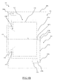
Figure 1A is an isometric view of a laundry machine in which the present invention may be implemented; -
Figure 1B is a schematic cross-sectional view of the laundry machine ofFigure 1A ; -
Figure 2 is a schematic diagram of laundry machine circuitry comprised in the laundry machine ofFigure 1 ; and -
Figure 3 - 6 are schematic diagrams of a portion of the control system designed for controlling a motor of the laundry machine in which different embodiments of the present invention are implemented. - With reference to the drawings,
Figures 1A and1B are isometric and cross-sectional views, respectively, of alaundry machine 100 in which the present invention may be implemented. - The
laundry machine 100 is a machine for treating laundry (such has a laundry washing machine, a laundry washing/drying machine, and possibly a laundry drying machine, etc.) of the front-loading type. Anyway, it should be apparent from the following description that laundry machines of the top-loading type may also benefit from the solution according to the present invention. - In the example at issue, the
laundry machine 100 comprises a casing orcabinet 105 preferably substantially parallelepiped-shaped, which encloses a washing tub, or simply tub, 107 (as shown inFigure 1B ) preferably substantially cylindrically-shaped, wherein the laundry is treated, along with any other component of thelaundry machine 100 necessary for its operation (e.g., hydraulic, electronic and electromechanical apparatuses as described in the following). - The
tub 107 houses arotatable drum 110 preferably substantially cylindrically shaped, which, in operation, rotates about an axis A in order to tumble the laundry to be washed. Typically, thetub 107 comprises, in a backside orbackwall 107a thereof, a shaft opening 107b, in which adrum rotor shaft 110a is inserted. Therotor shaft 110a is attached to thedrum 110 and rotatably connected by means of atransmission apparatus 115 to adrum motor 120, preferably electric, comprised in thelaundry machine 100 in order to rotate thedrum 110 during operation. Thedrum motor 120 is preferably, although not limitatively, positioned in a bottom position with respect to thecasing 105. Thetransmission apparatus 115 may comprise a transmission belt orchain 115a coupled with a pair ofpulleys first pulley 115b is mounted to thedrum rotor shaft 110a while asecond pulley 115c is mounted to amotor shaft 120a. Alternatively, in other embodiments according to the present invention (not shown in the Figures), the rotating movement may be transferred to the drum in any known manner; for example, a motor may be directly connected to the drum (so called "direct drive"), with the motor shaft coinciding to the drum shaft. - In order to allow a user to access the
tub 107 and the inside of the drum 110 (for loading/unloading the laundry), a loading/unloadingopening 125 is advantageously provided on a front side of thelaundry machine 100. Thetub 107 is provided with a tub opening 107c, and thedrum 110 is provided with adrum opening 110b. The tub opening 107c is adapted to be aligned with the loading/unloadingopening 125 provided in thecasing 105, and with the drum opening 110b of thedrum 110. - Preferably, in order to achieve a watertight connection between the loading/
unloading opening 125 and thetub opening 107b (in order to avoid leakages of washing liquid into the casing 105), abellows 130, preferably made of an elastomeric and waterproof material, is mounted in a watertight manner (such as by gluing, by welding, by interference fitting, etc.) to both a border of thetub opening 107c and a border of the loading/unloading opening 125. - The loading/
unloading opening 125 is closable by adoor 135, which is hinged, preferably, to thecasing 105 by means of a hinge (not shown in the figures). - The
tub 107 is fluidly connected with a hydraulic apparatus (not shown in the drawings) adapted to provide washing liquids (e.g., water mixed with detergents) in thewashing tub 107 for treating the laundry therein, and to exhaust such liquids once used. Thelaundry machine 100 may possibly comprise also a drying air apparatus (not shown) fluidly connected with thetub 107 adapted to heat up and blow drying air into the tub and draw therefrom moisturized cool air. - In addition, preferably, although not limitatively, on a
top portion 105t of the casing 105 auser interface 140 is provided. Preferably, although not limitatively, theuser interface 140 may comprise acontrol panel 140a for selecting laundry treatment cycles (e.g., a set of operations and parameters designed for treating peculiar fabrics, such as wool items) to be carried out by thelaundry machine 100, and adrawer 140b for loading laundry-treating products (e.g., detergents, softeners, bleachers, etc.). - The
laundry machine 100 is advantageously provided with a control unit 150 (e.g., comprising one or more microcontroller and/or other electronic devices) adapted to control thelaundry machine 100 operation (as discussed in the following), which is preferably, although not necessarily, placed in a top position inside the casing in order to be less prone to contacts with liquids or humidity possibly leaking from thetub 107. - Turning now to
Figure 2 , there is shown a schematic diagram of alaundry machine circuitry 200 comprised in thelaundry machine 100. - It should be readily understood that the term
laundry machine circuitry 200 is herein meant to denote generally the electric, electromechanical and electronic components provided in thelaundry machine 100. In other words, thelaundry machine circuitry 200 comprises elements of thelaundry machine 100 that (both directly or indirectly) require electric energy for their operation. - Preferably, the
laundry machine 100 is connected to the Mains through an electric cable element (not shown), such as an electric cord, which provides electric energy to thelaundry machine circuitry 200. For example, thelaundry machine 100 receives the line power signal at a line node L of thelaundry machine circuitry 200, while at a node N the neutral power signal is provided. - A voltage converter, such as a SMPS (Switching Mode Power Supply), 205 is connected to both line node L and neutral node N, thus receiving the electric energy from the Mains - usually provided with a 230V or 125V alternating voltage at a frequency of 50Hz or 60Hz, respectively. The
SMPS 205 is connected to acontrol system 210, feeding thereto one or more regulated supply voltages (e.g., 3V, 5V and 12V DC supply voltages with respect to a reference voltage at 0V also supplied by the SMPS 205), for example adapted to be supplied to electronic devices (such as microcontroller, sensor, memory devices, etc.) comprised in thecontrol system 210. Thecontrol system 210 comprises one or more sensor elements (not shown in the figure), each of which adapted to acquire part of an input information I related with the operation of one or more respective electric/electromechanical elements - denoted with 215 as a whole - provided in thelaundry machine 100 for the operation thereof (e.g., in order to perform the selected laundry treating cycle), which is controlled by output control signals O (as described in the following). In addition, thecontrol system 210 is advantageously adapted to receive a further part of the input information I set through thecontrol panel 140a by a user (such as a selected laundry treating cycle). - The one or more electric/
electromechanical elements 215 are, preferably, selectively connected to the line node L and the neutral node N by means of at least one respective switching element of aset 217 of switching elements (such as transistors, triacs, relays, etc.), controlled by the control system 210 (as described in the following). In the example at issue, the one or more electric/electromechanical elements 215 of thelaundry machine 100 advantageously comprises, in a nonlimiting way, adrain pump 225 in series with apump switching element 225a, awashing heater 230 in series with awashing switching element 230a, a drying apparatus 235 (e.g., an air heater element, a blower, etc.) in series with a dryingapparatus switching element 235a, a recirculation/drying apparatus actuator 240 (e.g., adapted to actuate a recirculation pump and/or a blower fan) in series with anactuator switching element 240a, thedrum motor 120 in series with a drummotor switching element 220a and a plurality of valves (e.g., adapted to hydraulically interconnect treating-product reservoirs and water inlet pipe), such as awash valve 245, apre-wash valve 250 and ableach valve 255 each in series with a respectivevalve switching element - Preferably, a
door switch 260 is provided between the line node L and part of the electric/electromechanical elements 215. For example, thedoor 135 may comprise mechanical, electromechanical or magnetic elements adapted to close thedoor switch 260 only when thedoor 135 is in the closed position. This is a security measure, which prevents the electric/electromechanical elements 215 downstream thedoor switch 260 from being operated while thedoor 135 is open; in this way, annoying and/or potentially harmful accident (e.g., liquids leakages and/or laundry items ejection caused byvalves door 135 is open) are avoided. - In addition, each of the electric/
electromechanical elements 215 comprising rotating parts (such as themotor 120 and/or recirculation/drying apparatus actuator 240 in the example at issue) may be selectively connected in opposite configurations to the line node L and to the neutral node N by means of relay elements (such relay elements are omitted inFigure 2 for the sake of simplicity since they are well known) to be rotated in different directions (as described in the following). Such relay elements are coupled in series between the line nodes L and N and the electric/electromechanical elements 215 comprising rotating parts, and are also connected to the control unit 150 (for receiving one of the output control signals O that select the configuration, as described in the following). - During operation, the
control system 210 is adapted to output one or more output control signals O, which are generally, but not limitatively, used for controlling the operation of thelaundry machine 100. For example, thecontrol system 210 ensures a selected laundry treating cycle (e.g., a wool items treating cycle) to be performed by the laundry machine. Thecontrol system 210 advantageously operates one or more switching element of theset 217 according to an acquired part of the input information I and/or associated operating instructions (e.g., sequences of activation of one or more electric/electromechanical elements 215 and/or predetermined operating time periods thereof) stored in a memory device (not shown) comprised in thecontrol system 210. Each sensor element converts a respective part of the acquired input information I (such as washing liquid/drying air temperatures, revolution per minutes of themotor 120, etc.) in a corresponding electrical signal provided to the control unit 150 (shown inFigure 3 ) comprised in the control system 210 (as discussed in the following). - In other embodiments of the present invention (not shown in the drawings), the control of the supplying of electric energy to the electric/
electromechanical elements 215 may be automatically performed by thecontrol system 210, for example, by automatically implementing an instructions set stored in the memory device of the control system 210 (e.g., thelaundry machine 100 may be adapted to automatically perform a predetermined laundry treating cycle). - Considering now
Figure 3 , it is a schematic diagram of aportion 300 of thecontrol system 210 designed for controlling the operation of thedrum motor 120 of thelaundry machine 100 in which an embodiment of the present invention is implemented. - The
control system 210 comprises a (angular) speed sensor, such as atachometer dynamo 310, preferably coupled with themotor shaft 120a of themotor 120. A pair of electrical connection elements, such as a couple ofwires tachometer dynamo 310 with thecontrol unit 150. - The
control unit 150 comprises aconditioning circuit 315 and acontroller 319. Theconditioning circuit 315 receives thefirst wire 317a of the couple at a first input In1 (e.g., a connector element provided on an electronic board, not shown, onto which component parts of thecontrol unit 150 are mounted), and thesecond wire 317b at a second input In2 (e.g., another connector element).Such wires motor 120 is positioned in a substantially opposite location with respect to thecontrol unit 150 inside thecasing 105, as can be appreciated inFigure 1 b. Moreover, theconditioning circuit 315 receives (e.g., from the SMPS 205) a first supply voltage VSMPS1 (e.g., 5V) at a first supply terminal Vs+, and a reference voltage VGND (e.g., 0V) at a second supply terminal Vs-. An output terminal Os of theconditioning circuit 315 is connected with a motor input terminal InM of thecontroller 319 mentioned above. - The
controller 319 receives a second supply voltage VSMPS2 (e.g., 5V) at a first supply terminal Vc+, and the reference voltage VGND at a second supply terminal Vc-, both provided by theSMPS 205. Thecontroller 319 is connected, by means of an output terminal OM, to a control terminal of the drum motor switching element, atriac 220a in the example at issue, coupled to thedrum motor 120. In order to allow themotor 120 being rotated in different directions (in order to rotate thedrum 110 in different directions too),relay elements drum motor 120.Such relay elements relay elements motor 120 in two opposite configurations with the line node L and the neutral node N (as well known in the art). For example, a first configuration causes the motor 120 (and the drum 110) to rotate in clockwise direction (e.g., with therelay elements motor 120 in a first manner), while a second configuration cause the same to rotate in counterclockwise direction (e.g., with therelay elements - According to one embodiment of the present invention the
control system 210 further comprises at least one impedance element, such as a resistor, implemented as anelectrical coupling member 325, connected between thefirst wire 317a and thesecond wire 317b. Advantageously, theelectrical coupling member 325 may be provided in proximity of theconditioning circuit 315; for example thecoupling member 325 may be positioned near to the connection between theconditioning circuit 315 and thewires electrical coupling member 325 may comprise one or more impedance elements other than a resistor. In some embodiments, the resistor may be replaced by another suitable impedance element (e.g., comprising inductors and capacitors) adapted to exhibits an impedance comprising a desired resistive value on a selected range of operative frequencies (e.g., a range of frequencies comprising the frequencies corresponding to angular speed of themotor 120 properly working). In other embodiments, an active element may be used ascoupling member 325. For example, a MOS transistor may be connected between thefirst wire 317a and thesecond wire 317b by means of conduction terminals thereof; whereas, a control gate of the MOS transistor may be biased (e.g., by the controller 319) for operating in triode region (i. e., with a desired resistive value). - During (normal) operating condition (i.e., when the
portion 300 of thecontrol system 210 works properly), thetachometer dynamo 310 provides an oscillating voltage VT that oscillates at a frequency proportional to the number of revolution per minutes (rpm) performed by themotor shaft 120a, and, for example having a maximum amplitude comprised between 50V and 100V. Theconditioning circuit 315 is adapted to convert such oscillating voltage VT into a conditioned signal adapted to be processed by thecontroller 319. For example, theconditioning circuit 315 may be adapted to convert the oscillating voltage VT into a (conditioned) square-wave signal VSq switching between the first supply voltage VSMPS1 and the reference voltage VGND at a frequency proportional to (e.g., equal to) the oscillating voltage VT. - The
controller 319 provides a motor control signal to thetriac 220a through the motor output terminal OM based on such conditioned signal. In detail, thecontroller 319 analyses the conditioned signal and determines if an actual rotating speed of themotor shaft 120a (and therefore of the drum 110) corresponds to a target rotating speed (e.g., defined by the operating instructions) or if the actual rotating speed has to be increased up or slowed down for catching such target rotating speed. Therefore, thecontroller 319 provides the motor control signal to thetriac 220a, which is alternatively opened and closed by the motor control signal in such a way to feed a required average amount of electric energy to themotor 120 for rotating themotor shaft 120a (and therefore of the drum 110) at the target rotating speed. For example, during each half-period of the alternating voltage from the Mains, in order to increase the rotating speed of themotor shaft 120a thetriac 220a is closed for a time interval longer than a complementary time interval in which is open; vice-versa, in order to slow down the rotating speed of themotor shaft 120a thetriac 220a is closed for a time interval shorter than a complementary time interval in which is open. - In (normal) operating condition, the
electrical coupling member 325 is preferably designed in order not to have any influence on theportion 300 of thecontrol system 210, which is controlling thedrum motor 120 operation. This can be achieved by designing the resistance RD of theelectrical coupling member 325 to be much greater than an equivalent resistance RT exhibited by the tachometer dynamo 310 (at thecoupling member 325 terminals) and than an equivalent resistance RW exhibited by thewires coupling member 325 terminals) when properly working; in this way, any electric current crossing theelectrical coupling member 325 will be of a negligible amount. In other words, the resistance RD of theelectrical coupling member 325 has to be grater than a total equivalent resistance Rtot exhibited by thewires tachometer dynamo 310 as can be detected at connecting terminals of the coupling member 325 (i.e., which connects thecoupling member 325 to thewires tachometer dynamo 310, which is usually comprised between 50-100Ω (although other resistance values are possible), and an equivalent resistance RW of eachwire electrical coupling member 325 equal, or greater than, 10KΩ, any electric current flowing through theelectrical coupling member 325 will have an intensity substantially equal to, or lower than, the approximately 0,5-1% of an intensity of a current flowing through thewires - Conversely, a failure condition occurs when a malfunction of the tachometer dynamo 310 (e.g., one or more component parts thereof break down or disconnect, thus impeding the
tachometer dynamo 310 from properly working), and/or of at least one of thefirst wire 317a and thesecond wire 317b (e.g., breaking or detaching from thetachometer dynamo 310 due to excessive operating oscillations) opens the connection between thetachometer dynamo 310 and theconditioning circuit 315. Therefore, the total equivalent resistance Rtot exhibited by thetachometer dynamo 310 and by thewires tachometer dynamo 310wires first wire 317a and thesecond wire 317b. The electrical coupling of theelectrical coupling member 325 with thefirst wire 317a and thesecond wire 317b exhibits an overall low impedance (substantially equal to the resistance RD itself) compared to the actual total equivalent resistance Rtot. It follows that, thanks to theelectrical coupling member 325, thewires wires electrical coupling member 325 interconnecting thefirst wire 317a with thesecond wire 317b. It should be noted that by positioning theelectrical coupling member 325 close to (or at) theconditioning circuit 315 inputs In1, and In2 a good robustness against mechanical stresses mentioned above thereof is achieved as well as a protection from failure conditions (e.g., at least awire wires - In such a failure condition, thanks to the
coupling member 325 theconditioning circuit 315 provides a constant electrical signal (e.g., a 5V voltage at 0Hz) to the motor input terminal InM of thecontroller 319, which is not interpreted as a fake speed indication (i.e., an oscillating spurious electrical signal). Advantageously, thecontroller 319 may be configured to identify a failure condition if the constant electrical signal is received at the motor input terminal InM whenever a not-null speed is expected according to the selected treating cycle. For example, thecontroller 319 may identify the failure condition whenever is received the constant electrical signal (instead of an oscillating electrical signal) while thecontroller 319 is driving thetriac 220a for actuating themotor 120. - Preferably, once a failure condition is identified, the
controller 319 may be configured for taking countermeasures to prevent damages to the laundry being treated, thelaundry machine 100 and/or the environment where thelaundry machine 100 is placed. For example, thecontroller 319 may be configured to set thetriac 220a in an open condition (i.e., disabling the drum motor 120), to activate an alarm (e.g., by activating an optical and/or acoustical alarm element provided in thecontrol panel 140a) and/or to complete the selected treating cycle in a safe mode (e.g., concluding the treating cycle without rotating the drum 110). - Preferably, although not limitatively, the
controller 319 may be configured to prevent any further activation of thedrum motor 120 after a failure condition is identified. A reset or ON/OFF element (e.g., a pushbutton not shown in the drawings) may be further provided in thecontrol panel 140a or in thecontrol system 210 in order to enable the operation of thedrum motor 120 again, once the origin of the failure has been overcome (e.g.,broken tachometer dynamo 310 and/orwires - Therefore, the
laundry machine 100 according to an embodiment of the present invention is able to safely avoid drawbacks due to electromagnetic fields - permeating the environment where thelaundry machine 100 is placed, and therefore thelaundry machine 100 itself - an energy of which may be converted by thewires - Considering now
Figure 4 , it is a schematic diagram of analternative portion 400 of thecontrol system 210 designed for controlling the operation of thedrum motor 120 of thelaundry machine 100 in which an another embodiment of the present invention is implemented. - The
portion 400 of thecontrol system 210 differs from theportion 300 previously described in the following. - The
portion 400 of thecontrol system 210 according to one embodiment of the present invention comprises a failure-check apparatus 430, which is connected to one between thewires controller 319, and adapted to identify a failure condition. For example, the failure-check apparatus 430 may be coupled to one of thewires conditioning circuit 315 and thewires check apparatus 430 may be connected to one of the inputs In1 and In2 of the conditioning circuit 315 (e.g., to one of the connectors on the electronic board mentioned above), obtaining the similar advantages to those mentioned above with respect to thecoupling member 325. - In the example at issue, the failure-
check apparatus 430 comprises afirst resistor 435, asecond resistor 440, acapacitor 445 and, preferably, but not limitatively, a pair ofdiode elements first resistor 435 is connected between thesecond wire 317b and a output node X of the failure-check apparatus 430, while thesecond resistor 440, thecapacitor 445 and the (first)diode element 450a are connected between the output node X and a reference terminal at the reference voltage VGND. The (second)diode element 450b is instead connected between the output node X and a supply terminal for receiving a third supply voltage VSMPS3 (e.g., 12V or 5V supplied by the SMPS 205). The output node X is connected to the failure input InF of thecontroller 319. Advantageously, theresistors electrical coupling member 325 and thecapacitor 445 provide a low-pass filter adapted to suppress (attenuating) any oscillating signals from thetachometer dynamo 310. - It should be clear that the structure of the failure-
check apparatus 430 described above is merely an illustrative embodiment which may subjected to several changes without departing from the scope of the present invention; particularly, other embodiments of the present invention are possible featuring a different number of resistors (i.e., just one resistor or more than two resistors). - The
controller 319 is advantageously adapted to verify if the failure condition occurs at predetermined time instants of the operation of thelaundry machine 100. Advantageously, thecontroller 319 may be configured for sensing the voltage signal received at the failure input InF during a startup phase of thelaundry machine 100, which is started by the power on of the laundry machine (e.g., by means of a power-on button provided in thecontrol panel 140a). Alternatively or in addition, thecontroller 319 may be configured for sensing the voltage signal received at the failure input InF just before starting a selected laundry treating cycle (e.g., selected by a user through thecontrol panel 140a). As a further alternative or addition, thecontroller 319 may be configured for sensing the voltage signal received at the failure input InF during each selected laundry treating cycle before any actuation of thedrum motor 120. Generally, thecontroller 319 is preferably configured for sensing the voltage signal received at the failure input InF at any time the rotation of themotor 120 is stopped, in order to substantially avoid any drawbacks mentioned above at any point of the operation of thelaundry machine 100. - During operation under normal condition, only a negligible electric current - drained from the
conditioning circuit 315 through the coupling member 325 - flows through thefirst resistor 435 towards the second resistor 440 (since any electric current is almost entirely absorbed by thetachometer dynamo 310 thanks to the low total equivalent resistance Rtot as previously described). The output node X is brought to a normal voltage value VXW (which is provided to the failure input terminal InF of the controller 319) substantially equal to the second supply voltage VSMPS2 (provided by the conditioning circuit 315). Thecontroller 319 is configured to identify the normal voltage value VXW as an indication of a normal working condition (e.g., by means of a comparator element, not shown); therefore, the operation of thelaundry machine 100 proceeds by implementing the selected treating cycle - Advantageously, the pair of (optional)
diode elements tachometer dynamo 310 exceeding a voltage operating range defined by the on voltage VD ofdiode elements controller 319. - Conversely, when a failure condition occurs (e.g., at least one between the
wires tachometer dynamo 310 fails), the electric current flowing through thefirst resistor 435 towards thesecond resistor 440 rapidly increases (since the total equivalent resistance Rtot rises, as previously discussed), and the output node X is brought to a failure voltage value VXF equal to the portion of the second supply voltage VSMPS2 across thesecond resistor 440. In other words, the failure voltage value VXF at output node X is determined by a voltage divider comprising thecoupling member 325, thefirst resistor 435 and thesecond resistor 440, or:
first resistor 435, and RF2 is the resistance of thesecond resistor 440. - When at the failure input terminal InF senses a voltage at the failure value VXF, the failure condition is detected. Therefore, countermeasure(s) may be taken; for example, preventing the
laundry machine operation 100 and/or activating an alarm (e.g., provided in thecontrol panel 140a). - Thanks to the failure condition control performed during the startup phase of the
laundry machine 100 by the failure-check apparatus 430 according to an embodiment of the present invention, it is possible to prevent any uncontrolled actuation of thedrum motor 120 and of the rotation of thedrum 110, nullifying (or at least minimizing) any harmful drawbacks mentioned above. - It should be readily understood that, in a further embodiment according to the present invention, the failure-
check apparatus 430 may be connected to thefirst wire 317a instead to thesecond wire 317b as well. In such case (not shown) the voltage divider, now comprising theresistors controller 319. - Moreover, in yet another further embodiment according to the present invention, the
coupling element 325 may be omitted, with the failure-check apparatus 430 that alone allow thecontrol circuit 150 to prevent the actuation of thedrum 110 during a failure condition of thespeed sensor 310 and/or of thewires - It should also be appreciated that an alternative failure-
check apparatus 430 could be designed for providing a different electrical quantity other than a voltage in order to identify the failure conditions. For example, an alternative failure-check apparatus (not shown) may be implemented for providing a predetermined electric current value to thecontroller 319 when a failure conditions is identified. - Turning now to
Figure 5 , it is a schematic diagram of analternative portion 500 of thecontrol system 210 designed for controlling the operation of thedrum motor 120 of thelaundry machine 100 in which a further embodiment of the present invention is implemented. - The
portion 500 of thecontrol system 210 differs from theportion 400 previously described in the following. - The failure-
check apparatus 430 is preferably, although not limitatively, selectively connected to thesecond wire 317b by means of a failure-check switching element 555 (e.g., a transistor), which may advantageously be connected to a failure output terminal OF of thecontroller 319 through a respective control terminal to be operated by thecontroller 319. - At the predetermined time instants (e.g., at power on of the
control unit 150, before a predetermined laundry treating cycle, and/or before any activation of thedrum motor 120 as previously described), the failure-check apparatus 430 is connected to theelectrical coupling member 325 by providing a closing signal at a closure value (e.g., a constant voltage at 5V) to the control terminal of the failure-check switching element 555, which closes. Then the voltage value received at the failure input terminal InF is sensed as previously discussed. Once the failure check is performed, the failure output terminal OF provides the closing signal at an opening value (e.g., a constant voltage at 0V) to the failure-check switching element 555, which opens, thus disconnecting the failure-check apparatus 430 from thesecond wire 317b and theelectrical coupling member 325. - Subsequently, the operation of the
laundry machine 100 may be prevented and other countermeasure(s) such as the ones mentioned above may be performed, or the operation of thelaundry machine 100 may normally start according to whether a failure condition has been detected or as not been detected, respectively. - During the operation under normal condition, the
controller 319 maintains the failure-check switching element 555 in an open condition by providing the closing signal at the opening value to the control terminal of the failure-check switching element 555 through the fail-check output terminal OF. Under this condition, the failure-check apparatus 430 is disconnected from the considered part of thecontrol system 210, neither substantially consuming electric energy nor providing any signal to the fail-check input port InF. - It should be understood that a further failure-check apparatus (not shown) may be implemented, in which the failure-
check switching element 555 could be directly connected to thewire 317a (in such case changes to the resistor may be required as previously discussed). - Also in this case, a further embodiment (not shown) according to the present invention may be provided in which the
coupling element 325 is omitted. - Finally, it should be promptly understood that thanks to the solution according to the present invention it is also possible to prevent the driving of the
motor 120 also in the case the latter incurs in a malfunction that prevents the same from rotating; thus avoiding the drawbacks caused by amotor 120 failure, such as overheating or sparks produced by malfunctioning of the (according to the type of electric motor implied) rotor or stator windings, and/or electrical brushes thereof.
Claims (15)
- A laundry machine (100) for treating laundry items comprising a drum (110) adapted to house the laundry to be treated, a motor (120) arranged for rotating the drum, a control system (210) adapted to adjust the operation of the laundry machine at least partially based on acquired operating information,
said control system (210) comprising at least one speed sensor (310) adapted to provide an electrical signal containing information on a rotating speed of the motor (120), at least two electrical connection elements (317a, 317b) adapted to electrically connect the speed sensor (310) to a control unit (150) for transferring the electrical signal from the speed sensor (310) to the control unit (150), said control unit (150) being operable to receive said electrical signal and adjust the rotating speed of the motor (120) accordingly,
characterized in that
the control system (210) further comprises at least one electrical coupling member (325) adapted to electrically interconnect said two electrical connection elements (317a, 317b) for preventing said two electrical connection elements (317a, 317b) from acting as a receiver of electromagnetic fields permeating the laundry machine (100), and/or
a failure-check apparatus (430) connected to either one of said two electrical connection elements (317a, 317b), the failure-check apparatus (430) being adapted to provide to the control unit (150) an electrical signal identifying a failure condition in which at least one of said two electrical connection elements (317a, 317b) and/or the speed sensor (310) is subjected to a malfunction. - The laundry machine (100) according to claim 1, wherein the at least one electrical coupling member (325) comprises at least one impedance element.
- The laundry machine (100) according to claim 1 or 2, wherein the speed sensor (310) and the at least two electrical connection elements (317a, 317b) exhibit a first value of the total equivalent resistance in an operating condition, when the speed sensor (310) and the at least two electrical connection elements (317a, 317b) operate properly, or a second value of the total equivalent resistance in a failure operating condition, when the speed sensor (310) or at least one of the at least two electrical connection elements (317a, 317b) is subjected to a malfunction, the first value of the total equivalent resistance being lower than the second value of the total equivalent resistance, and wherein the impedance element of the coupling member (325) exhibits a resistance that is higher than the first value of the total equivalent resistance of the speed sensor (310) and the at least two electrical connection elements (317a, 317b) and is lower than the second value of the total equivalent resistance of the speed sensor (310) and the at least two electrical connection elements (317a, 317b).
- The laundry machine (100) according to any one of the preceding claims 1 to 3, wherein the control unit (150) is electrically connected to an output node (X) of the failure-check apparatus (430) for receiving the electrical signal, the failure-check apparatus (430) comprising at least one resistive element (435, 440) forming at least part of a voltage divider, said voltage divider being adapted to provide the electrical signal at the output node (X) to be received by the control unit (150) .
- The laundry machine (100) according to claim 4, wherein the voltage divider further comprises the electrical coupling member (325), and/or at least one further resistive element (435, 440).
- The laundry machine (100) according to claim 4 or 5, wherein the at least one resistive element (435, 440) comprises a first resistive element (435) connected to either one of said two electrical connection elements (317a, 317b), a second resistive element (440) connected with the first resistive element (435) at the output node (X) and connected to a reference terminal for receiving a reference voltage.
- The laundry machine (100) according to any one of the preceding claims 1 to 6, wherein the failure-check apparatus (430) further comprises a first diode element (450a) connected between the common node and the reference terminal, and a second diode element (450b) connected between a supply terminal for receiving a supply voltage and the output node, the first diode (450a) and second diode (450b) elements being adapted to clamp a voltage below an upper value and above a lower value, respectively.
- The laundry machine (100) according to any one of the preceding claims 4 to 7, wherein the failure-check apparatus (430) further comprises at least one capacitive element (445) connected between the output node (X) and the reference terminal, the capacitive element (445) and the at least one resistive element (435, 440) forming a low-pass filter configured to cut off high-frequency electrical signals.
- The laundry machine (100) according to any one of the preceding claims 1 to 8, wherein the control unit (150) is configured to receive the electrical signal from the failure-check apparatus (430) when the motor is not actuated.
- The laundry machine (100) according to any one of the preceding claims 1 to 9, wherein the laundry machine further comprises a control panel (140a) adapted to allow a user to select at least one laundry treating cycle, and
wherein the control unit (150) is configured to receive the electrical signal from the failure-check apparatus (430) at a power on of the control unit (150) before actuating the motor (120), and/or
the control unit (150) is configured to receive the electrical signal from the failure-check apparatus (430) before performing the selected at least one laundry treating cycle, and/or
the control unit (150) is configured to receive the electrical signal from the failure-check apparatus (430) before any actuation of the motor (120) during the execution of the selected at least one laundry treating cycle. - The laundry machine (100) according to any one of the preceding claims 1 to 10, further comprising a switching element (555) connected between either one of said two electrical connection elements (317a, 317b) and the failure-check apparatus (430), said switching element (555) being operable by the control unit (150) to selectively electrically connect either one of said two electrical connection elements (317a, 317b) and the failure-check apparatus (430).
- The laundry machine (100) according to claim 11, wherein the control unit (150) is configured to provide a closing signal at a closing value for closing the switching element (555) only when the motor (120) is not actuated, and to provide the closing signal at an opening value for opening the switching element (555) before actuating the motor (120).
- The laundry machine (100) according to claim 11 or 12, further comprising a control panel (140a) adapted to allow a user to select at least one laundry treating cycle, and
wherein the control unit (150) is configured to provide the closing signal for closing the switching element (555) at a power-on of the control unit (150), and/or
the control unit (150) is configured to provide the closing signal for closing the switching element (555) before performing the selected at least one laundry treating cycle, and/or
the control (150) unit is configured to provide the closing signal for closing the switching element (555) before any actuation of the motor (120) during the execution of the selected at least one laundry treating cycle. - The laundry machine (100) according to any of the preceding claims 4 to 13, wherein the control unit (150) is configured to prevent the drum (110) rotation once the electrical signal at the second value is received.
- The laundry machine (100) according to any of the preceding claims 4 to 14, wherein the control unit (150) is configured to actuate an alarm element once the electrical signal at the second value is received.
Priority Applications (3)
| Application Number | Priority Date | Filing Date | Title |
|---|---|---|---|
| EP13156301.7A EP2770101B1 (en) | 2013-02-22 | 2013-02-22 | Laundry machine |
| PL13156301T PL2770101T3 (en) | 2013-02-22 | 2013-02-22 | Laundry machine |
| PCT/EP2014/053351 WO2014128226A1 (en) | 2013-02-22 | 2014-02-20 | Laundry machine |
Applications Claiming Priority (1)
| Application Number | Priority Date | Filing Date | Title |
|---|---|---|---|
| EP13156301.7A EP2770101B1 (en) | 2013-02-22 | 2013-02-22 | Laundry machine |
Publications (2)
| Publication Number | Publication Date |
|---|---|
| EP2770101A1 true EP2770101A1 (en) | 2014-08-27 |
| EP2770101B1 EP2770101B1 (en) | 2021-09-29 |
Family
ID=47750483
Family Applications (1)
| Application Number | Title | Priority Date | Filing Date |
|---|---|---|---|
| EP13156301.7A Active EP2770101B1 (en) | 2013-02-22 | 2013-02-22 | Laundry machine |
Country Status (3)
| Country | Link |
|---|---|
| EP (1) | EP2770101B1 (en) |
| PL (1) | PL2770101T3 (en) |
| WO (1) | WO2014128226A1 (en) |
Citations (4)
| Publication number | Priority date | Publication date | Assignee | Title |
|---|---|---|---|---|
| DE19733533A1 (en) * | 1997-08-02 | 1999-02-04 | Ako Werke Gmbh & Co | Monitoring circuit for control of washing machine motor |
| EP2020721A2 (en) * | 2007-08-03 | 2009-02-04 | BSH Bosch und Siemens Hausgeräte GmbH | Switching assembly for monitoring a tachometer for a drive motor of a drum of a washing machine |
| DE102008007563A1 (en) * | 2008-02-05 | 2009-08-06 | BSH Bosch und Siemens Hausgeräte GmbH | Circuit arrangement for e.g. monitoring tachometer that is used for detecting speed of motor of washer dryer, has control terminal connected with voltage source by switching resistance that has high resistance than ohmic resistance |
| WO2013007511A2 (en) * | 2011-07-11 | 2013-01-17 | BSH Bosch und Siemens Hausgeräte GmbH | Method for controlling the rotational speed of an electric drive motor of a household appliance, and household appliance |
-
2013
- 2013-02-22 EP EP13156301.7A patent/EP2770101B1/en active Active
- 2013-02-22 PL PL13156301T patent/PL2770101T3/en unknown
-
2014
- 2014-02-20 WO PCT/EP2014/053351 patent/WO2014128226A1/en active Application Filing
Patent Citations (4)
| Publication number | Priority date | Publication date | Assignee | Title |
|---|---|---|---|---|
| DE19733533A1 (en) * | 1997-08-02 | 1999-02-04 | Ako Werke Gmbh & Co | Monitoring circuit for control of washing machine motor |
| EP2020721A2 (en) * | 2007-08-03 | 2009-02-04 | BSH Bosch und Siemens Hausgeräte GmbH | Switching assembly for monitoring a tachometer for a drive motor of a drum of a washing machine |
| DE102008007563A1 (en) * | 2008-02-05 | 2009-08-06 | BSH Bosch und Siemens Hausgeräte GmbH | Circuit arrangement for e.g. monitoring tachometer that is used for detecting speed of motor of washer dryer, has control terminal connected with voltage source by switching resistance that has high resistance than ohmic resistance |
| WO2013007511A2 (en) * | 2011-07-11 | 2013-01-17 | BSH Bosch und Siemens Hausgeräte GmbH | Method for controlling the rotational speed of an electric drive motor of a household appliance, and household appliance |
Also Published As
| Publication number | Publication date |
|---|---|
| EP2770101B1 (en) | 2021-09-29 |
| WO2014128226A1 (en) | 2014-08-28 |
| PL2770101T3 (en) | 2022-02-07 |
Similar Documents
| Publication | Publication Date | Title |
|---|---|---|
| RU2572732C2 (en) | Fault monitoring in heating coil of household appliances | |
| AU2013211628A1 (en) | Laundry treating machine | |
| US9817052B2 (en) | Method and circuit for determining dispersion of electric power towards ground in electric appliances | |
| US20140285929A1 (en) | Ground Power Leakage Detection for Peripheral Printed Circuit Boards | |
| WO2011141555A1 (en) | Heating circuit with monitoring arrangement for a household appliance | |
| US20150028016A1 (en) | Inrush Current Control System | |
| EP2770101B1 (en) | Laundry machine | |
| WO2009000690A1 (en) | A washer/dryer | |
| EP2887525B1 (en) | System for monitoring electric loads and for monitoring driving apparatuses of said electric loads | |
| JP2005312570A (en) | Washing machine | |
| EP3249089B1 (en) | Laundry treatment appliance | |
| EP2376698B1 (en) | A household appliance wherein the heating of its pump motor is controlled | |
| EP3020859A1 (en) | Laundry treating machine | |
| EP2416226B1 (en) | Washing machine having alternatively operating electric loads | |
| TWI825356B (en) | washing machine | |
| WO2015011863A1 (en) | Electrical appliance | |
| CN105759206B (en) | A kind of detection protection system of fan condition | |
| JP2018007290A (en) | Household electric appliance, washing machine, and washing/drying machine | |
| RU2575219C2 (en) | Electric household appliance for products processing | |
| EP2638196B1 (en) | A washer/dryer comprising a relay determining rotational direction of the motor | |
| JP2005312569A (en) | Washing machine | |
| EP3348697A1 (en) | Appliance comprising one or more sensors | |
| KR20100092766A (en) | Apparatus for protecting a washing machine from an overcurrent | |
| WO2014087339A1 (en) | Laundry washing machine with protection circuit | |
| WO2012175545A1 (en) | Printed circuit board for household appliances |
Legal Events
| Date | Code | Title | Description |
|---|---|---|---|
| PUAI | Public reference made under article 153(3) epc to a published international application that has entered the european phase |
Free format text: ORIGINAL CODE: 0009012 |
|
| 17P | Request for examination filed |
Effective date: 20130222 |
|
| AK | Designated contracting states |
Kind code of ref document: A1 Designated state(s): AL AT BE BG CH CY CZ DE DK EE ES FI FR GB GR HR HU IE IS IT LI LT LU LV MC MK MT NL NO PL PT RO RS SE SI SK SM TR |
|
| AX | Request for extension of the european patent |
Extension state: BA ME |
|
| STAA | Information on the status of an ep patent application or granted ep patent |
Free format text: STATUS: REQUEST FOR EXAMINATION WAS MADE |
|
| R17P | Request for examination filed (corrected) |
Effective date: 20150226 |
|
| RBV | Designated contracting states (corrected) |
Designated state(s): AL AT BE BG CH CY CZ DE DK EE ES FI FR GB GR HR HU IE IS IT LI LT LU LV MC MK MT NL NO PL PT RO RS SE SI SK SM TR |
|
| GRAP | Despatch of communication of intention to grant a patent |
Free format text: ORIGINAL CODE: EPIDOSNIGR1 |
|
| STAA | Information on the status of an ep patent application or granted ep patent |
Free format text: STATUS: GRANT OF PATENT IS INTENDED |
|
| RIC1 | Information provided on ipc code assigned before grant |
Ipc: D06F 37/30 20200101ALI20210428BHEP Ipc: D06F 37/42 20060101AFI20210428BHEP |
|
| INTG | Intention to grant announced |
Effective date: 20210519 |
|
| GRAS | Grant fee paid |
Free format text: ORIGINAL CODE: EPIDOSNIGR3 |
|
| GRAA | (expected) grant |
Free format text: ORIGINAL CODE: 0009210 |
|
| STAA | Information on the status of an ep patent application or granted ep patent |
Free format text: STATUS: THE PATENT HAS BEEN GRANTED |
|
| AK | Designated contracting states |
Kind code of ref document: B1 Designated state(s): AL AT BE BG CH CY CZ DE DK EE ES FI FR GB GR HR HU IE IS IT LI LT LU LV MC MK MT NL NO PL PT RO RS SE SI SK SM TR |
|
| REG | Reference to a national code |
Ref country code: GB Ref legal event code: FG4D |
|
| REG | Reference to a national code |
Ref country code: DE Ref legal event code: R096 Ref document number: 602013079434 Country of ref document: DE |
|
| REG | Reference to a national code |
Ref country code: CH Ref legal event code: EP Ref country code: AT Ref legal event code: REF Ref document number: 1434279 Country of ref document: AT Kind code of ref document: T Effective date: 20211015 |
|
| REG | Reference to a national code |
Ref country code: IE Ref legal event code: FG4D |
|
| REG | Reference to a national code |
Ref country code: LT Ref legal event code: MG9D |
|
| PG25 | Lapsed in a contracting state [announced via postgrant information from national office to epo] |
Ref country code: RS Free format text: LAPSE BECAUSE OF FAILURE TO SUBMIT A TRANSLATION OF THE DESCRIPTION OR TO PAY THE FEE WITHIN THE PRESCRIBED TIME-LIMIT Effective date: 20210929 Ref country code: NO Free format text: LAPSE BECAUSE OF FAILURE TO SUBMIT A TRANSLATION OF THE DESCRIPTION OR TO PAY THE FEE WITHIN THE PRESCRIBED TIME-LIMIT Effective date: 20211229 Ref country code: FI Free format text: LAPSE BECAUSE OF FAILURE TO SUBMIT A TRANSLATION OF THE DESCRIPTION OR TO PAY THE FEE WITHIN THE PRESCRIBED TIME-LIMIT Effective date: 20210929 Ref country code: LT Free format text: LAPSE BECAUSE OF FAILURE TO SUBMIT A TRANSLATION OF THE DESCRIPTION OR TO PAY THE FEE WITHIN THE PRESCRIBED TIME-LIMIT Effective date: 20210929 Ref country code: BG Free format text: LAPSE BECAUSE OF FAILURE TO SUBMIT A TRANSLATION OF THE DESCRIPTION OR TO PAY THE FEE WITHIN THE PRESCRIBED TIME-LIMIT Effective date: 20211229 Ref country code: SE Free format text: LAPSE BECAUSE OF FAILURE TO SUBMIT A TRANSLATION OF THE DESCRIPTION OR TO PAY THE FEE WITHIN THE PRESCRIBED TIME-LIMIT Effective date: 20210929 Ref country code: HR Free format text: LAPSE BECAUSE OF FAILURE TO SUBMIT A TRANSLATION OF THE DESCRIPTION OR TO PAY THE FEE WITHIN THE PRESCRIBED TIME-LIMIT Effective date: 20210929 |
|
| REG | Reference to a national code |
Ref country code: NL Ref legal event code: MP Effective date: 20210929 |
|
| REG | Reference to a national code |
Ref country code: AT Ref legal event code: MK05 Ref document number: 1434279 Country of ref document: AT Kind code of ref document: T Effective date: 20210929 |
|
| PG25 | Lapsed in a contracting state [announced via postgrant information from national office to epo] |
Ref country code: LV Free format text: LAPSE BECAUSE OF FAILURE TO SUBMIT A TRANSLATION OF THE DESCRIPTION OR TO PAY THE FEE WITHIN THE PRESCRIBED TIME-LIMIT Effective date: 20210929 Ref country code: GR Free format text: LAPSE BECAUSE OF FAILURE TO SUBMIT A TRANSLATION OF THE DESCRIPTION OR TO PAY THE FEE WITHIN THE PRESCRIBED TIME-LIMIT Effective date: 20211230 |
|
| PG25 | Lapsed in a contracting state [announced via postgrant information from national office to epo] |
Ref country code: AT Free format text: LAPSE BECAUSE OF FAILURE TO SUBMIT A TRANSLATION OF THE DESCRIPTION OR TO PAY THE FEE WITHIN THE PRESCRIBED TIME-LIMIT Effective date: 20210929 |
|
| PG25 | Lapsed in a contracting state [announced via postgrant information from national office to epo] |
Ref country code: IS Free format text: LAPSE BECAUSE OF FAILURE TO SUBMIT A TRANSLATION OF THE DESCRIPTION OR TO PAY THE FEE WITHIN THE PRESCRIBED TIME-LIMIT Effective date: 20220129 Ref country code: SK Free format text: LAPSE BECAUSE OF FAILURE TO SUBMIT A TRANSLATION OF THE DESCRIPTION OR TO PAY THE FEE WITHIN THE PRESCRIBED TIME-LIMIT Effective date: 20210929 Ref country code: RO Free format text: LAPSE BECAUSE OF FAILURE TO SUBMIT A TRANSLATION OF THE DESCRIPTION OR TO PAY THE FEE WITHIN THE PRESCRIBED TIME-LIMIT Effective date: 20210929 Ref country code: PT Free format text: LAPSE BECAUSE OF FAILURE TO SUBMIT A TRANSLATION OF THE DESCRIPTION OR TO PAY THE FEE WITHIN THE PRESCRIBED TIME-LIMIT Effective date: 20220131 Ref country code: NL Free format text: LAPSE BECAUSE OF FAILURE TO SUBMIT A TRANSLATION OF THE DESCRIPTION OR TO PAY THE FEE WITHIN THE PRESCRIBED TIME-LIMIT Effective date: 20210929 Ref country code: ES Free format text: LAPSE BECAUSE OF FAILURE TO SUBMIT A TRANSLATION OF THE DESCRIPTION OR TO PAY THE FEE WITHIN THE PRESCRIBED TIME-LIMIT Effective date: 20210929 Ref country code: EE Free format text: LAPSE BECAUSE OF FAILURE TO SUBMIT A TRANSLATION OF THE DESCRIPTION OR TO PAY THE FEE WITHIN THE PRESCRIBED TIME-LIMIT Effective date: 20210929 Ref country code: CZ Free format text: LAPSE BECAUSE OF FAILURE TO SUBMIT A TRANSLATION OF THE DESCRIPTION OR TO PAY THE FEE WITHIN THE PRESCRIBED TIME-LIMIT Effective date: 20210929 Ref country code: AL Free format text: LAPSE BECAUSE OF FAILURE TO SUBMIT A TRANSLATION OF THE DESCRIPTION OR TO PAY THE FEE WITHIN THE PRESCRIBED TIME-LIMIT Effective date: 20210929 |
|
| REG | Reference to a national code |
Ref country code: DE Ref legal event code: R097 Ref document number: 602013079434 Country of ref document: DE |
|
| PG25 | Lapsed in a contracting state [announced via postgrant information from national office to epo] |
Ref country code: DK Free format text: LAPSE BECAUSE OF FAILURE TO SUBMIT A TRANSLATION OF THE DESCRIPTION OR TO PAY THE FEE WITHIN THE PRESCRIBED TIME-LIMIT Effective date: 20210929 |
|
| PLBE | No opposition filed within time limit |
Free format text: ORIGINAL CODE: 0009261 |
|
| STAA | Information on the status of an ep patent application or granted ep patent |
Free format text: STATUS: NO OPPOSITION FILED WITHIN TIME LIMIT |
|
| 26N | No opposition filed |
Effective date: 20220630 |
|
| PG25 | Lapsed in a contracting state [announced via postgrant information from national office to epo] |
Ref country code: MC Free format text: LAPSE BECAUSE OF FAILURE TO SUBMIT A TRANSLATION OF THE DESCRIPTION OR TO PAY THE FEE WITHIN THE PRESCRIBED TIME-LIMIT Effective date: 20210929 |
|
| REG | Reference to a national code |
Ref country code: CH Ref legal event code: PL |
|
| REG | Reference to a national code |
Ref country code: BE Ref legal event code: MM Effective date: 20220228 |
|
| GBPC | Gb: european patent ceased through non-payment of renewal fee |
Effective date: 20220222 |
|
| PG25 | Lapsed in a contracting state [announced via postgrant information from national office to epo] |
Ref country code: LU Free format text: LAPSE BECAUSE OF NON-PAYMENT OF DUE FEES Effective date: 20220222 |
|
| PG25 | Lapsed in a contracting state [announced via postgrant information from national office to epo] |
Ref country code: SI Free format text: LAPSE BECAUSE OF FAILURE TO SUBMIT A TRANSLATION OF THE DESCRIPTION OR TO PAY THE FEE WITHIN THE PRESCRIBED TIME-LIMIT Effective date: 20210929 |
|
| PG25 | Lapsed in a contracting state [announced via postgrant information from national office to epo] |
Ref country code: FR Free format text: LAPSE BECAUSE OF NON-PAYMENT OF DUE FEES Effective date: 20220228 |
|
| PG25 | Lapsed in a contracting state [announced via postgrant information from national office to epo] |
Ref country code: LI Free format text: LAPSE BECAUSE OF NON-PAYMENT OF DUE FEES Effective date: 20220228 Ref country code: IE Free format text: LAPSE BECAUSE OF NON-PAYMENT OF DUE FEES Effective date: 20220222 Ref country code: GB Free format text: LAPSE BECAUSE OF NON-PAYMENT OF DUE FEES Effective date: 20220222 Ref country code: CH Free format text: LAPSE BECAUSE OF NON-PAYMENT OF DUE FEES Effective date: 20220228 |
|
| PG25 | Lapsed in a contracting state [announced via postgrant information from national office to epo] |
Ref country code: BE Free format text: LAPSE BECAUSE OF NON-PAYMENT OF DUE FEES Effective date: 20220228 |
|
| PGFP | Annual fee paid to national office [announced via postgrant information from national office to epo] |
Ref country code: PL Payment date: 20230130 Year of fee payment: 11 Ref country code: IT Payment date: 20230220 Year of fee payment: 11 Ref country code: DE Payment date: 20230227 Year of fee payment: 11 |
|
| P01 | Opt-out of the competence of the unified patent court (upc) registered |
Effective date: 20230625 |
|
| PG25 | Lapsed in a contracting state [announced via postgrant information from national office to epo] |
Ref country code: HU Free format text: LAPSE BECAUSE OF FAILURE TO SUBMIT A TRANSLATION OF THE DESCRIPTION OR TO PAY THE FEE WITHIN THE PRESCRIBED TIME-LIMIT; INVALID AB INITIO Effective date: 20130222 |
|
| PG25 | Lapsed in a contracting state [announced via postgrant information from national office to epo] |
Ref country code: SM Free format text: LAPSE BECAUSE OF FAILURE TO SUBMIT A TRANSLATION OF THE DESCRIPTION OR TO PAY THE FEE WITHIN THE PRESCRIBED TIME-LIMIT Effective date: 20210929 Ref country code: MK Free format text: LAPSE BECAUSE OF FAILURE TO SUBMIT A TRANSLATION OF THE DESCRIPTION OR TO PAY THE FEE WITHIN THE PRESCRIBED TIME-LIMIT Effective date: 20210929 Ref country code: CY Free format text: LAPSE BECAUSE OF FAILURE TO SUBMIT A TRANSLATION OF THE DESCRIPTION OR TO PAY THE FEE WITHIN THE PRESCRIBED TIME-LIMIT Effective date: 20210929 |