EP2768289A1 - Röntgenvorrichtung mit personentransportablem Strahlungsmodul - Google Patents
Röntgenvorrichtung mit personentransportablem Strahlungsmodul Download PDFInfo
- Publication number
- EP2768289A1 EP2768289A1 EP13155648.2A EP13155648A EP2768289A1 EP 2768289 A1 EP2768289 A1 EP 2768289A1 EP 13155648 A EP13155648 A EP 13155648A EP 2768289 A1 EP2768289 A1 EP 2768289A1
- Authority
- EP
- European Patent Office
- Prior art keywords
- ray
- examination
- radiation
- module
- unit
- Prior art date
- Legal status (The legal status is an assumption and is not a legal conclusion. Google has not performed a legal analysis and makes no representation as to the accuracy of the status listed.)
- Granted
Links
- 230000005855 radiation Effects 0.000 claims abstract description 68
- 238000001514 detection method Methods 0.000 claims abstract description 55
- 238000000034 method Methods 0.000 claims abstract description 9
- 238000007789 sealing Methods 0.000 claims description 5
- 239000000523 sample Substances 0.000 description 33
- 238000010894 electron beam technology Methods 0.000 description 6
- XAGFODPZIPBFFR-UHFFFAOYSA-N aluminium Chemical compound [Al] XAGFODPZIPBFFR-UHFFFAOYSA-N 0.000 description 4
- 229910052782 aluminium Inorganic materials 0.000 description 4
- 239000010405 anode material Substances 0.000 description 3
- 238000011161 development Methods 0.000 description 3
- 238000011835 investigation Methods 0.000 description 3
- 230000005461 Bremsstrahlung Effects 0.000 description 2
- 238000011156 evaluation Methods 0.000 description 2
- 230000003993 interaction Effects 0.000 description 2
- 230000001133 acceleration Effects 0.000 description 1
- 230000001419 dependent effect Effects 0.000 description 1
- 230000000694 effects Effects 0.000 description 1
- 238000003780 insertion Methods 0.000 description 1
- 230000037431 insertion Effects 0.000 description 1
- 238000007689 inspection Methods 0.000 description 1
- 239000000463 material Substances 0.000 description 1
- 238000012986 modification Methods 0.000 description 1
- 230000004048 modification Effects 0.000 description 1
- 239000004065 semiconductor Substances 0.000 description 1
- 238000000926 separation method Methods 0.000 description 1
- 230000001131 transforming effect Effects 0.000 description 1
- 230000007704 transition Effects 0.000 description 1
- 230000005472 transition radiation Effects 0.000 description 1
Images

Classifications
-
- G—PHYSICS
- G01—MEASURING; TESTING
- G01N—INVESTIGATING OR ANALYSING MATERIALS BY DETERMINING THEIR CHEMICAL OR PHYSICAL PROPERTIES
- G01N23/00—Investigating or analysing materials by the use of wave or particle radiation, e.g. X-rays or neutrons, not covered by groups G01N3/00 – G01N17/00, G01N21/00 or G01N22/00
- G01N23/02—Investigating or analysing materials by the use of wave or particle radiation, e.g. X-rays or neutrons, not covered by groups G01N3/00 – G01N17/00, G01N21/00 or G01N22/00 by transmitting the radiation through the material
- G01N23/06—Investigating or analysing materials by the use of wave or particle radiation, e.g. X-rays or neutrons, not covered by groups G01N3/00 – G01N17/00, G01N21/00 or G01N22/00 by transmitting the radiation through the material and measuring the absorption
- G01N23/083—Investigating or analysing materials by the use of wave or particle radiation, e.g. X-rays or neutrons, not covered by groups G01N3/00 – G01N17/00, G01N21/00 or G01N22/00 by transmitting the radiation through the material and measuring the absorption the radiation being X-rays
-
- H—ELECTRICITY
- H01—ELECTRIC ELEMENTS
- H01J—ELECTRIC DISCHARGE TUBES OR DISCHARGE LAMPS
- H01J35/00—X-ray tubes
- H01J35/02—Details
- H01J35/14—Arrangements for concentrating, focusing, or directing the cathode ray
-
- H—ELECTRICITY
- H05—ELECTRIC TECHNIQUES NOT OTHERWISE PROVIDED FOR
- H05G—X-RAY TECHNIQUE
- H05G1/00—X-ray apparatus involving X-ray tubes; Circuits therefor
- H05G1/02—Constructional details
- H05G1/04—Mounting the X-ray tube within a closed housing
- H05G1/06—X-ray tube and at least part of the power supply apparatus being mounted within the same housing
-
- G—PHYSICS
- G01—MEASURING; TESTING
- G01N—INVESTIGATING OR ANALYSING MATERIALS BY DETERMINING THEIR CHEMICAL OR PHYSICAL PROPERTIES
- G01N2223/00—Investigating materials by wave or particle radiation
- G01N2223/30—Accessories, mechanical or electrical features
- G01N2223/301—Accessories, mechanical or electrical features portable apparatus
-
- H—ELECTRICITY
- H01—ELECTRIC ELEMENTS
- H01J—ELECTRIC DISCHARGE TUBES OR DISCHARGE LAMPS
- H01J35/00—X-ray tubes
- H01J35/02—Details
- H01J35/04—Electrodes ; Mutual position thereof; Constructional adaptations therefor
- H01J35/08—Anodes; Anti cathodes
- H01J35/112—Non-rotating anodes
- H01J35/116—Transmissive anodes
Definitions
- the invention relates to an X-ray device according to the preamble of claim 1.
- the high voltage power supply unit providing a high voltage for operation of an x-ray tube is stationary due to its high weight and size and connected to the X-ray tube via high-diameter power cables.
- the X-ray tube is also arranged stationary and at most pivotable, so that examination objects must be transported to the X-ray device.
- it is therefore difficult to investigate using X-ray radiation.
- a compact, person-transportable X-ray device which in particular comprises a transportable high-voltage supply unit and can thus be transported to examination objects.
- the object of the invention is in particular to provide an X-ray device with improved transportability properties.
- the object is achieved by the features of claim 1 solved, while advantageous embodiments and modifications of the invention can be taken from the dependent claims.
- the invention is based on an X-ray device having at least one high-voltage supply unit, at least one X-ray radiation unit for generating an X-ray beam, at least one focusing unit for focusing the X-ray beam, and at least one X-ray detection unit.
- the x-ray device has a person-transportable radiation module which comprises the at least one high-voltage supply unit together with the at least one x-ray radiation unit.
- an "X-ray device” should be understood to mean, in particular, a device which at least generates X-ray radiation and preferably makes available the X-radiation in a previously defined beam shape for use, for example for an examination of an examination subject.
- the X-ray device has at least one X-ray tube for generating X-ray radiation.
- X-radiation is meant in particular a photon radiation having a wavelength between about ten nanometers and a picometer.
- An "X-ray tube” is to be understood in particular as a unit in which electrons, which emerge from a cathode, are accelerated to an X-ray anode by a high voltage, and, on impact with an anode material of the X-ray anode, by electromagnetic interaction with atoms in the anode material be slowed down and X-ray radiation generated in the form of Bremsstrahlung, on the other hand, inner shell electrons knock out of atomic shells of the atoms of the anode material, with a resulting hole in the atomic shell below Emission of a photon to X-radiation, which is called characteristic X-radiation, is filled by outer sheath electrons, and on the other hand by a called Lilienfeld radiation transition radiation at an interface transition of the accelerated electrons between materials with different permittivity X-radiation is generated.
- a "high-voltage supply unit” is to be understood in particular as a unit which, by transforming an input voltage of at most 100 V, advantageously at most 60 V and preferably at most 40 V, a high voltage, in particular a high voltage to an acceleration of electrons of at least 80 kV, advantageously at least 90 kV and preferably generated by at least 100 kV.
- Modern high-voltage power supply units according to the prior art have at least a weight of 60 kg and a volume of at least 0.4 m 3 and thus can only be operated stationary.
- the prior art high voltage power supplies are too large and too heavy to be packaged together with an X-ray unit in a passenger-transportable module.
- a "focusing unit for focusing the X-ray beam” is to be understood in particular as meaning a unit with permanent and / or electromagnets which is intended to focus a beam of accelerated electrons on a predetermined area in order to receive a focused beam of X-ray radiation at the X-ray anode produce.
- the focusing unit is designed to focus the electrodes in a so-called microfocus with a focal spot of not more than 10 ⁇ m, advantageously not more than 8 ⁇ m and preferably not more than 4 ⁇ m.
- An "X-ray detection unit” is intended in particular to be a unit for detecting X-ray radiation, which in particular permits detection of an incident amount of X-ray radiation and spatial resolution, for example scintillator screens, gas ionization detectors or semiconductor detectors.
- a “module” is to be understood as meaning, in particular, a closed unit comprising a plurality of subunits which belong to one subsystem Interaction with other units and preferably to a connection with other units is provided.
- the module has a module housing which surrounds the subunits in their entirety.
- a "person-transportable module” is to be understood in particular as a module that is transported by a maximum of three persons, preferably a maximum of two persons and preferably by a person with hands over a distance of at least twenty meters, advantageously at least fifty meters and preferably at least one hundred meters can.
- the passenger-transportable module has a volume of not more than 0.15 m 3 and a maximum weight of 90 kg.
- the radiation module have a volume of not more than 0.032 m 3 , advantageously of not more than 0.025 m 3 and preferably not more than 0.016 m 3 .
- a person-transportable module can be achieved by a single person.
- the radiation module has a maximum weight of 50 kg, advantageously not more than 40 kg and preferably not more than 30 kg.
- a radiation-transmissable by a single person person radiation module can be achieved
- the radiation module comprises the at least one focusing unit.
- the radiation module which makes available a focused X-ray beam and thus an X-ray pretreated completely for use.
- the x-ray device comprises a person-transportable detection module which has the at least one x-ray detection unit.
- the detection module is provided for connection to the radiation module.
- an easily transportable X-ray device can be achieved.
- the detection module has at least one connection region which is provided for connection to the radiation module and / or a sample chamber.
- a "connection region” is to be understood, in particular, as a region provided specifically for a connection, which has at least one contact region which is provided for a precisely fitting contact with a partial region of the radiation module and which preferably has fastening means for fastening the detection module to the radiation module.
- a particularly robust x-ray device and a largely interference-free detection of x-radiation emitted by the radiation module can be achieved.
- the X-ray device comprises at least one sample chamber to a recording of an examination subject.
- a "sample chamber” is to be understood in particular as meaning a unit with a free space into which an examination object can be introduced as a sample.
- the sample chamber has locking elements for attachment of the sample.
- a distance of the sample from an entry point of the X-ray radiation into the sample chamber and thus an achieved enlargement of an image by X-radiation can be varied.
- an x-ray device can be achieved which allows an advantageously trouble-free examination of a sample and a variable magnification.
- the X-ray device has at least one sealing unit which is provided to seal a connection between the radiation module and / or the detection module and / or the sample chamber.
- the sealing unit may be formed, for example, as a unit with at least one O-ring.
- a connection of the radiation module and / or the detection module which is largely shielded from disturbance influences, and / or reached the sample chamber and X-ray examinations are made possible under vacuum conditions.
- An x-ray examination method with an x-ray device is proposed in which the x-ray device is transported to an object examination of at least one first examination subject in a first examination zone and transported to an object examination by at least one second examination subject in a second examination zone.
- An "examination area” should be understood to mean in particular an area, preferably a room, in which the at least one object is arranged and which is in particular different from an area specially designed as an X-ray area with a permanently installed X-ray tube and a permanently installed high-voltage supply in the examination objects be transported to an object investigation.
- an x-ray examination method can be achieved with a high degree of flexibility in use of the x-ray device and, in particular, with low requirements for premises for carrying out an object examination.
- the radiation module of the X-ray device be arranged for an examination of an examination object at or immediately before a partial area of the examination subject and the detection module at or immediately before a further partial area of the examination subject.
- the detection module in at least one operating state, can be separated from the sample chamber and / or the radiation module in order to irradiate at least one examination object in a gap between the radiation module and the detection module.
- an X-ray examination of objects that are too large for introduction into the at least one sample chamber, and / or subcomponents of a component that is too large for insertion may be achieved without a need to disassemble the larger unit.
- subcomponents Components which could be damaged during removal from the component can therefore be examined particularly easily.
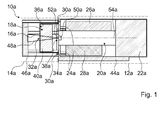
- Fig. 1 shows an inventive X-ray device 10a with a high voltage supply unit 22a, an X-ray unit 20a for generating an X-ray beam 48a, a focusing unit 24a for focusing the X-ray beam 48a, a turbomolecular pump 28a, a Power supply unit 26a for the focusing unit 24a and with an X-ray detection unit 16a and a sample chamber 18a.
- the high voltage supply unit 22a transforms an input voltage of 40 V, which is supplied via not shown power supply lines of the X-ray device 10a, at a maximum current of 6 A into a high voltage of 100 kV.
- the X-ray unit 20a electrons are released from a cathode formed as a heatable wire and accelerated from the high voltage of the high voltage power supply unit 22a in an electron beam 54a to an X-ray anode 50a in an operation by a glow electric effect.
- X-radiation is generated by Bremsstrahlung, characteristic X-radiation and Lilienfeldstrahlung.
- the X-ray 48a exits through an aluminum window 52a.
- the focusing unit 24a designed as an electron optics has electromagnets which are supplied with current for generating a magnetic field via the power supply unit 26a, by means of which the electron beam 54a is focused onto a focal spot with a diameter of 4 ⁇ m in the x-ray anode 50a.
- the turbomolecular pump 28a generates a high vacuum in a region of the radiation module 12a in which the electron beam 54a extends in order to avoid an expansion of the electron beam 54a.
- An external backing pump, not shown, is used in addition to the turbomolecular pump 28a.
- the X-ray device 10a comprises a person-portable radiation module 12a, which comprises the high-voltage supply unit 22a together with the X-radiation unit 20a, the focusing unit 24a, the turbomolecular pump 28a and the power supply unit 26a and is mounted within a module housing 44a.
- the radiation module 12a has a volume of 0.1575 m 3 and a weight of 35 kg.
- the X-ray device 10a further comprises a person transportable Detection module 14a, which has the X-ray detection unit 16a.
- the X-ray detection unit 16a comprises a scintillator screen, a photodetection unit for detecting scintillator light and an evaluation unit for an electronic evaluation.
- the detection module 14a has a module housing 46a, in which the x-ray detection unit 16a and a sample chamber 18a form a receptacle of an examination object 40a, which is integrated in the detection module 14a. Furthermore, a USB interface for forwarding the data of the X-ray detection unit 16a is integrated in the detection module 14a.
- an examination subject 40a is fixed by means of locking means, whereby a distance of the examination subject 40a to the aluminum window 52a and thus a starting point of the x-ray beam 48a can be varied, whereby an achievable resolution can be varied.
- inspection objects 40a having a maximum diameter of 175 mm and a maximum length of 95 mm can be mounted.
- the module housings 44a, 46a of the radiation module 12a and of the detection module 14a protect an environment of the x-ray device 10a from an exit of x-ray radiation.
- the detection module 14a has a connection region 32a, which is provided for connecting the detection module 14a to the radiation module 12a, and to which the detection module 14a is connected to a corresponding connection region 34a of the radiation module 12a.
- the connection of the detection module 14a with the radiation module 12a is effected by means not shown fastening means of the connecting portions 32a, 34a.
- the sample chamber 18a has a connection region 36a for connection to the detection module 14a and a connection region 38a for connection to the radiation module 12a.
- the connection region 38a is connected to the corresponding connection region 34a of the radiation module 12a.
- the X-ray device 10a comprises a sealing unit 30a, which is designed as an O-ring seal and a connection between the radiation module 12a and the detection module 14a and the sample chamber 18a seals.
- a total length of the X-ray device 10a is 687 mm and a total weight 43 kg.
- the X-ray device 10a In an X-ray examination method with the X-ray device 10a, the X-ray device 10a is transported to an object examination of at least one first examination object 40a in a first examination area and transported to an object examination of at least one second examination object in a second examination area. Transport of the X-ray device 10a is made possible by forming the radiation module 12a and the detection module 14a as passenger-transportable modules. By the X-ray examination method with a transport of the X-ray device 10a, it is avoided to have to build a separate X-ray area with a fixed X-ray source. The radiation module 12a and the detection module 14a can be separated from each other for easier transportation.
- Fig. 2 and Fig. 3 a further embodiment of the invention is shown.
- the following descriptions and the drawings are essentially limited to the differences between the exemplary embodiments, wherein with respect to the same named components, in particular with respect to components with the same reference numerals, in principle to the drawing and / or the description of the other embodiment, in particular Fig. 1 , is referenced.
- To distinguish the embodiments of the letter a is the reference numerals of the embodiment of Fig. 1 readjusted.
- the letter a is replaced by the letter b.
- An alternative X-ray device 10b is substantially analogous to that shown in the previous embodiment and includes a personal transportable radiation module 12b comprising a high voltage supply unit 22b together with an X-ray unit 20b, a focusing unit 24b, a turbomolecular pump 28b and a power supply unit 26b and mounted within a module housing 44b ( Fig. 2 ).
- the personal transportable radiation module 12b has a volume of 0.1575 m 3 and a weight of 35 kg.
- the X-ray device 10b further comprises a person-portable detection module 14b, which has an X-ray detection unit 16b and a module housing 46b, and a sample chamber 18b for receiving an examination subject 40a.
- the sample chamber 18b has a connection region 36b for connection to a corresponding connection region 32b on the module housing 46b of the detection module 14b, and a connection region 38b for connection to a corresponding connection region 34b on the module housing 44b of the radiation module 12b.
- the sample chamber 18b is disposed between the detection module 14b and the radiation module 12b.
- a seal unit 30b designed as an O-ring seal seals a connection of the radiation module 12b with the sample chamber 18b.
- a total length of the X-ray device 10a is 687 mm and a total weight is 43 kg.
- examination objects 40b having a maximum diameter of 175 mm and a maximum length of 95 mm can be mounted by means of locking means which are introduced through a closable opening on the sample chamber 18b.
- the X-ray device 10b is transported to an object examination of at least one first examination object 40b in a first examination area and transported to an object examination of at least one second examination object in a second examination area.
- the sample chamber 18b may be dismounted from the radiation module 12b and the detection module 14b ( Fig. 3 ).
- the radiation module 12b of the x-ray device 10b is arranged to examine an examination object 42b at or immediately before a partial area of the examination object 42b and the detection module 14b at or immediately before another partial area of the examination object 42b.
- An X-ray beam 48b exiting through an aluminum window 52b is detected after passing through the examination object 42b by means of the X-ray detection unit 16b of the detection module 14b, which is arranged opposite to the radiation module 12b.
Landscapes
- Health & Medical Sciences (AREA)
- Toxicology (AREA)
- Physics & Mathematics (AREA)
- Life Sciences & Earth Sciences (AREA)
- Chemical & Material Sciences (AREA)
- Analytical Chemistry (AREA)
- Biochemistry (AREA)
- General Health & Medical Sciences (AREA)
- General Physics & Mathematics (AREA)
- Immunology (AREA)
- Pathology (AREA)
- Analysing Materials By The Use Of Radiation (AREA)
Abstract
Description
- Die Erfindung betrifft eine Röntgenvorrichtung nach dem Oberbegriff des Anspruchs 1.
- Bei Röntgenvorrichtungen nach dem gegenwärtigen Stand der Technik, die zu einer Erzeugung eines Röntgenstrahls für eine Durchleuchtung eines Objekts im Zuge einer Untersuchung vorgesehen sind, ist die Hochspannungsversorgungseinheit, die eine Hochspannung für einen Betrieb einer Röntgenröhre bereitstellt, aufgrund ihres hohen Gewichts und ihrer Größe stationär eingebaut und mit der Röntgenröhre über Stromkabel mit einem hohen Durchmesser verbunden. Meist ist die Röntgenröhre ebenfalls stationär angeordnet und allenfalls schwenkbar ausgebildet, sodass Untersuchungsobjekte zu der Röntgenvorrichtung transportiert werden müssen. Insbesondere bei großen Untersuchungsobjekten oder Untersuchungsobjekten, die einen integralen Bestandteil eines Objekts bilden und nur schwer oder gar nicht demontiert werden können, ist somit eine Untersuchung mittels Röntgenstrahlung nur schwer möglich. Es besteht somit ein Bedarf an einer kompakten, personentransportablen Röntgenvorrichtung, die insbesondere eine transportable Hochspannungsversorgungseinheit umfasst und somit zu Untersuchungsobjekten transportiert werden kann.
- Die Aufgabe der Erfindung besteht insbesondere darin, eine Röntgenvorrichtung mit verbesserten Eigenschaften hinsichtlich einer Transportabilität bereitzustellen. Die Aufgabe wird erfindungsgemäß durch die Merkmale des Patentanspruchs 1 gelöst, während vorteilhafte Ausgestaltungen und Weiterbildungen der Erfindung den Unteransprüchen entnommen werden können.
- Die Erfindung geht aus von einer Röntgenvorrichtung mit zumindest einer Hochspannungsversorgungseinheit, zumindest einer Röntgenstrahlungseinheit zur Erzeugung eines Röntgenstrahls, zumindest einer Fokussierungseinheit zu einer Fokussierung des Röntgenstrahls, und mit zumindest einer Röntgendetektionseinheit.
- Es wird vorgeschlagen, dass die Röntgenvorrichtung ein personentransportables Strahlungsmodul aufweist, das die zumindest eine Hochspannungsversorgungseinheit zusammen mit der zumindest einen Röntgenstrahlungseinheit umfasst.
- Unter einer "Röntgenvorrichtung" soll insbesondere eine Vorrichtung verstanden werden, die Röntgenstrahlung zumindest erzeugt und vorzugsweise die Röntgenstrahlung in einer vorher festgelegt Strahlenform für eine Nutzung, beispielsweise für eine Untersuchung eines Untersuchungsobjekts, zur Verfügung stellt. Insbesondere weist die Röntgenvorrichtung zu einer Erzeugung von Röntgenstrahlung zumindest eine Röntgenröhre auf. Unter "Röntgenstrahlung" soll insbesondere eine Photonenstrahlung mit einer Wellenlänge zwischen etwa zehn Nanometern und einem Pikometer verstanden werden. Unter einer "Röntgenröhre" soll insbesondere eine Einheit verstanden werden, in der durch eine Hochspannung Elektronen, die aus einer Kathode austreten, auf eine Röntgenanode beschleunigt werden, und bei einem Auftreffen auf ein Anodenmaterial der Röntgenanode zum Einen durch elektromagnetische Wechselwirkung mit Atomen in dem Anodenmaterial abgebremst werden und Röntgenstrahlung in Form von Bremsstrahlung erzeugt, zum Anderen innere Hüllenelektronen aus Atomhüllen der Atome des Anodenmaterials herausschlagen, wobei ein dabei entstehendes Loch in der Atomhülle unter Aussendung eines Photons an Röntgenstrahlung, die als charakteristische Röntgenstrahlung bezeichnet wird, von äußeren Hüllenelektronen aufgefüllt wird, und zum Anderen durch eine als Lilienfeldstrahlung bezeichnete Übergangsstrahlung bei einem Grenzflächenübergang der beschleunigten Elektronen zwischen Materialien mit unterschiedlicher Permittivität Röntgenstrahlung erzeugt wird. Unter einer "Hochspannungsversorgungseinheit" soll insbesondere eine Einheit verstanden werden, die durch Hochtransformation einer Eingangsspannung von maximal 100 V, vorteilhaft maximal 60 V und bevorzugt maximal 40 V eine Hochspannung, insbesondere eine Hochspannung zu einer Beschleunigung von Elektronen, von zumindest 80 kV, vorteilhaft von zumindest 90 kV und bevorzugt von zumindest 100 kV erzeugt. Moderne Hochspannungsversorgungseinheiten nach dem Stand der Technik weisen zumindest ein Gewicht von 60 kg und einen Rauminhalt von zumindest 0,4 m3 auf und können somit lediglich stationär betrieben werden. Insbesondere sind die Hochspannungsversorgungseinheiten nach dem Stand der Technik zu groß und zu schwer, um zusammen mit einer Röntgenstrahlungseinheit in einem personentransportablen Modul zusammengefasst zu werden. Unter einer "Fokussierungseinheit zu einer Fokussierung des Röntgenstrahls" soll insbesondere eine Einheit mit Permanent- und/oder Elektromagneten verstanden werden, die dazu vorgesehen ist, einen Strahl beschleunigter Elektronen auf einen vorbestimmten Bereich zu fokussieren, um einen fokussierten Strahl von Röntgenstrahlung an der Röntgenanode zu erzeugen. Vorzugsweise ist die Fokussierungseinheit dazu ausgebildet, die Elektroden in einen sogenannten Mikrofokus mit einem Brennfleck von maximal 10 pm, vorteilhaft maximal 8 µm und bevorzugt maximal 4 µm zu fokussieren. Unter einer "Röntgendetektionseinheit" soll insbesondere eine Einheit zu einer Detektion von Röntgenstrahlung, die insbesondere eine Detektion einer auftreffenden Strahlenmenge an Röntgenstrahlung und eine Ortsauflösung erlaubt, beispielsweise Szintillatorschirme, Gasionisationsdetektoren oder Halbleiterdetektoren. Unter einem "Modul" soll insbesondere eine abgeschlossene Einheit aus mehreren Teileinheiten verstanden werden, die zu einem Zusammenwirken mit anderen Einheiten und vorzugweise zu einer Verbindung mit anderen Einheiten vorgesehen ist. Vorzugsweise weist das Modul ein Modulgehäuse auf, das die Teileinheiten im Gesamten umgibt. Unter einem "personentransportablen Modul" soll insbesondere ein Modul verstanden werden, dass von maximal drei Personen, vorteilhaft von maximal zwei Personen und bevorzugt von einer Person mit Händen über eine Strecke von zumindest zwanzig Metern, vorteilhaft zumindest fünfzig Metern und vorzugsweise zumindest einhundert Metern transportiert werden kann. Insbesondere weist das personentransportable Modul einen Rauminhalt von maximal 0,15 m3 und ein Gewicht von maximal 90 kg auf. Es kann insbesondere eine flexibel einsetzbare Röntgenvorrichtung erreicht werden, mit der auch unter beengten Verhältnissen Untersuchungen vorgenommen werden können.
- In einer Weiterbildung der Erfindung wird vorgeschlagen, dass das Strahlungsmodul einen Rauminhalt von maximal 0,032 m3, vorteilhaft von maximal 0,025 m3 und bevorzugt von maximal 0,016 m3 aufweist. Es kann insbesondere ein von einer einzelnen Person personentransportables Modul erreicht werden.
- Weiterhin wird vorgeschlagen, dass das Strahlungsmodul ein Gewicht von maximal 50 kg, vorteilhaft maximal 40 kg und bevorzugt maximal 30 kg aufweist. Es kann insbesondere ein von einer einzelnen Person personentransportables Strahlungsmodul erreicht werden
- Ferner wird vorgeschlagen, dass das Strahlungsmodul die zumindest eine Fokussierungseinheit umfasst. Es kann insbesondere ein Strahlungsmodul zur Verfügung gestellt werden, das einen fokussierten Röntgenstrahl und somit einen komplett zu einer Verwendung vorbehandelten Röntgenstrahl zur Verfügung stellt.
- Es wird weiterhin vorgeschlagen, dass die Röntgenvorrichtung ein personentransportables Detektionsmodul umfasst, das die zumindest eine Röntgendetektionseinheit aufweist. Vorzugsweise ist das Detektionsmodul zu einer Verbindung mit dem Strahlungsmodul vorgesehen. Es kann insbesondere eine einfach transportable Röntgenvorrichtung erreicht werden.
- In einer Weiterbildung der Erfindung wird vorgeschlagen, dass das Detektionsmodul zumindest einen Verbindungsbereich aufweist, der zu einer Verbindung mit dem Strahlungsmodul und/oder einer Probenkammer vorgesehen ist. Unter einem "Verbindungsbereich" soll insbesondere ein speziell zu einer Verbindung vorgesehener Bereich verstanden werden, der zumindest einen Kontaktbereich aufweist, der zu einem passgenauen Kontakt zu einem Teilbereich des Strahlungsmoduls vorgesehen ist und der vorzugsweise Befestigungsmittel zu einer Befestigung des Detektionsmoduls an dem Strahlungsmodul aufweist. Es kann insbesondere eine besonders robust ausgeführte Röntgenvorrichtung und eine weitgehend störungsfreie Detektion von durch das Strahlungsmodul ausgesandter Röntgenstrahlung erreicht werden.
- Des Weiteren wird vorgeschlagen, dass die Röntgenvorrichtung zumindest eine Probenkammer zu einer Aufnahme eines Untersuchungsobjekts umfasst. Unter einer "Probenkammer" soll insbesondere eine Einheit mit einem freien Raum, in die ein Untersuchungsobjekt als eine Probe eingebracht werden kann, verstanden werden. Insbesondere weist die Probenkammer Arretierungselemente zu einer Befestigung der Probe auf. Vorteilhaft kann mittels der Arretierungselemente ein Abstand der Probe von einem Eintrittspunkt der Röntgenstrahlung in die Probenkammer und somit eine erzielte Vergrößerung einer Abbildung durch Röntgenstrahlung variiert werden. Es kann insbesondere eine Röntgenvorrichtung erreicht werden, die eine vorteilhaft störungsfreie Untersuchung einer Probe und eine variable Vergrößerung ermöglicht.
- Ferner wird vorgeschlagen, dass die Röntgenvorrichtung zumindest eine Dichtungseinheit aufweist, die dazu vorgesehen ist, eine Verbindung zwischen dem Strahlungsmodul und/oder dem Detektionsmodul und/oder der Probenkammer abzudichten. Insbesondere kann die Dichtungseinheit beispielsweise als eine Einheit mit zumindest einem O-Ring ausgebildet sein. Es kann insbesondere eine weitgehend von Störungseinflüssen abgeschirmte Verbindung von dem Strahlungsmodul und/oder dem Detektionsmodul und/oder der Probenkammer erreicht und Röntgenuntersuchungen unter Vakuumbedingungen ermöglicht werden.
- Es wird ein Röntgenuntersuchungsverfahren mit einer erfindungsgemäßen Röntgenvorrichtung vorgeschlagen, bei dem die Röntgenvorrichtung zu einer Objektuntersuchung von zumindest einem ersten Untersuchungsobjekt in einen ersten Untersuchungsbereich transportiert und zu einer Objektuntersuchung von zumindest einem zweiten Untersuchungsobjekt in einen zweiten Untersuchungsbereich transportiert wird. Unter einem "Untersuchungsbereich" soll insbesondere ein Bereich, vorzugsweise ein Raum verstanden werden, in dem das zumindest eine Objekt angeordnet ist und der insbesondere verschieden ist von einem speziell als Röntgenbereich ausgebildeten Bereich mit einer fest installierten Röntgenröhre und einer fest installierten Hochspannungsversorgung, in den Untersuchungsobjekte zu einer Objektuntersuchung transportiert werden. Es kann insbesondere ein Röntgenuntersuchungsverfahren mit einer hohen Flexibilität in einem Einsatz der Röntgenvorrichtung und besonders mit geringen Anforderungen an Räumlichkeiten zu einer Durchführung einer Objektuntersuchung erreicht werden.
- In einer Weiterbildung der Erfindung wird vorgeschlagen, dass das Strahlungsmodul der Röntgenvorrichtung zu einer Untersuchung eines Untersuchungsobjekts an oder unmittelbar vor einem Teilbereich des Untersuchungsobjekts und das Detektionsmodul an oder unmittelbar vor einem weiteren Teilbereich des Untersuchungsobjekts angeordnet werden. Insbesondere kann in zumindest einem Betriebszustand das Detektionsmodul von der Probenkammer und/oder dem Strahlungsmodul abgetrennt werden, um zumindest ein Untersuchungsobjekt in einem Zwischenraum zwischen dem Strahlungsmodul und dem Detektionsmodul zu durchstrahlen. Es kann insbesondere eine Untersuchung mittels Röntgenstrahlung von Objekten, die für eine Einbringung in die zumindest einen Probenkammer zu groß sind, und/oder von Teilkomponenten eines Bauteils, dass für die Einbringung zu groß ist, ohne eine Notwendigkeit einer Zerlegung der größeren Einheit erreicht werden. Insbesondere Teilkomponenten von Bauteilen, welche bei einem Ausbau aus dem Bauteil beschädigt werden könnten, können somit besonders einfach untersucht werden.
- Weitere Vorteile ergeben sich aus der folgenden Zeichnungsbeschreibung. In den Zeichnungen sind zwei Ausführungsbeispiele der Erfindung dargestellt. Die Zeichnungen, die Beschreibung und die Ansprüche enthalten zahlreiche Merkmale in Kombination. Der Fachmann wird die Merkmale zweckmäßigerweise auch einzeln betrachten und zu sinnvollen weiteren Kombinationen zusammenfassen.
- Es zeigen:
- Fig. 1
- eine schematische Darstellung einer erfindungsgemäßen Röntgenvorrichtung mit einem Strahlungsmodul und einem Detektionsmodul mit integrierter Probenkammer,
- Fig. 2
- eine schematische Darstellung einer alternativen erfindungsgemäßen Röntgenvorrichtung mit einem Strahlungsmodul, einem Detektionsmodul und mit einer Probenkammer, in der zu einer Objektuntersuchung eine Probe montiert ist, und
- Fig. 3
- eine schematische Darstellung der alternativen erfindungsgemäßen Röntgenvorrichtung mit dem Strahlungsmodul und dem Detektionsmodul, die voneinander getrennt an unterschiedlichen Teilbereichen eines Untersuchungsobjekts angeordnet sind.
-
Fig. 1 zeigt eine erfindungsgemäße Röntgenvorrichtung 10a mit einer Hochspannungsversorgungseinheit 22a, einer Röntgenstrahlungseinheit 20a zur Erzeugung eines Röntgenstrahls 48a, einer Fokussierungseinheit 24a zu einer Fokussierung des Röntgenstrahls 48a, einer Turbomolekularpumpe 28a, einer Stromversorgungseinheit 26a für die Fokussierungseinheit 24a und mit einer Röntgendetektionseinheit 16a und einer Probenkammer 18a. Die Hochspannungsversorgungseinheit 22a transformiert eine Eingangsspannung von 40 V, die über nicht dargestellte Stromversorgungsleitungen der Röntgenvorrichtung 10a zugeführt wird, bei einer maximalen Stromstärke von 6 A in eine Hochspannung von 100 kV. In der Röntgenstrahlungseinheit 20a werden in einem Betrieb mittels eines glühelektrischen Effekts Elektronen aus einer als ein heizbarer Draht ausgebildeten Kathode freigesetzt und von der Hochspannung der Hochspannungsversorgungseinheit 22a in einem Elektronenstrahl 54a auf eine Röntgenanode 50a zu beschleunigt. Bei einem Auftreffen beschleunigter Elektronen des Elektronenstrahls 54a auf die Röntgenanode 50a wird Röntgenstrahlung durch Bremsstrahlung, charakteristische Röntgenstrahlung und Lilienfeldstrahlung erzeugt. Die Röntgenstrahlung 48a tritt durch ein Aluminiumfenster 52a aus. Die als Elektronenoptik ausgebildete Fokussierungseinheit 24a weist Elektromagnete auf, die über die Stromversorgungseinheit 26a mit Strom zur Erzeugung eines Magnetfelds versorgt werden, mittels dem der Elektronenstrahl 54a auf einen Brennfleck mit einem Durchmesser von 4 µm in der Röntgenanode 50a fokussiert wird. Die Turbomolekularpumpe 28a erzeugt ein Hochvakuum in einem Bereich des Strahlungsmoduls 12a, in dem der Elektronenstrahl 54a verläuft, um eine Aufweitung des Elektronenstrahls 54a zu vermeiden. Eine nicht dargestellte, externe Vorvakuumpumpe wird zusätzlich zu der Turbomolekularpumpe 28a verwendet. - Die Röntgenvorrichtung 10a umfasst ein personentransportables Strahlungsmodul 12a, das die Hochspannungsversorgungseinheit 22a zusammen mit der Röntgenstrahlungseinheit 20a, der Fokussierungseinheit 24a, der Turbomolekularpumpe 28a und der Stromversorgungseinheit 26a umfasst und innerhalb eines Modulgehäuses 44a befestigt. Das Strahlungsmodul 12a weist einen Rauminhalt von 0,1575 m3 und ein Gewicht von 35 kg auf. Die Röntgenvorrichtung 10a umfasst ferner ein personentransportables Detektionsmodul 14a, das die Röntgendetektionseinheit 16a aufweist. Die Röntgendetektionseinheit 16a umfasst einen Szintillatorschirm, eine Photodetektionseinheit zu Detektion von Szintillatorlicht und eine Auswerteeinheit zu einer elektronischen Auswertung. Das Detektionsmodul 14a weist ein Modulgehäuse 46a auf, dass die Röntgendetektionseinheit 16a und eine Probenkammer 18a zu einer Aufnahme eines Untersuchungsobjekts 40a, die in das Detektionsmodul 14a integriert ist, auf. Des Weiteren ist in das Detektionsmodul 14a eine USB-Schnittstelle zu einer Weiterleitung der Daten der Röntgendetektionseinheit 16a integriert. In der Probenkammer 18a ist ein Untersuchungsobjekt 40a mittels Arretierungsmitteln befestigt, wobei ein Abstand des Untersuchungsobjekts 40a zu dem Aluminiumfenster 52a und somit einem Ausgangspunkt des Röntgenstrahls 48a variiert werden kann, wodurch eine erzielbare Auflösung variiert werden kann. In der Probenkammer 18a können Untersuchungsobjekte 40a mit einem Maximaldurchmesser von 175 mm und einer Maximallänge von 95 mm montiert werden. Die Modulgehäuse 44a, 46a des Strahlungsmoduls 12a und des Detektionsmoduls 14a schützen eine Umgebung der Röntgenvorrichtung 10a gegenüber einem Austritt von Röntgenstrahlung.
- Das Detektionsmodul 14a weist einen Verbindungsbereich 32a auf, der zu einer Verbindung des Detektionsmoduls 14a mit dem Strahlungsmodul 12a vorgesehen ist und an dem das Detektionsmodul 14a mit einem korrespondierenden Verbindungsbereich 34a des Strahlungsmoduls 12a verbunden ist. Die Verbindung des Detektionsmoduls 14a mit dem Strahlungsmodul 12a wird mittels nicht dargestellter Befestigungsmittel der Verbindungsbereiche 32a, 34a bewirkt. Die Probenkammer 18a weist einen Verbindungsbereich 36a zu einer Verbindung mit dem Detektionsmodul 14a und einen Verbindungsbereich 38a zu einer Verbindung mit dem Strahlungsmodul 12a auf. Der Verbindungsbereich 38a ist mit dem korrespondierenden Verbindungsbereich 34a des Strahlungsmoduls 12a verbunden. Die Röntgenvorrichtung 10a umfasst eine Dichtungseinheit 30a, die als eine O-Ring-Dichtung ausgeführt ist und eine Verbindung zwischen dem Strahlungsmodul 12a und dem Detektionsmodul 14a und der Probenkammer 18a abdichtet. Eine Gesamtlänge der Röntgenvorrichtung 10a beträgt 687 mm und ein Gesamtgewicht 43 kg.
- In einem Röntgenuntersuchungsverfahren mit der Röntgenvorrichtung 10a wird die Röntgenvorrichtung 10a zu einer Objektuntersuchung von zumindest einem ersten Untersuchungsobjekt 40a in einen ersten Untersuchungsbereich transportiert und zu einer Objektuntersuchung von zumindest einem zweiten Untersuchungsobjekt in einen zweiten Untersuchungsbereich transportiert. Ein Transport der Röntgenvorrichtung 10a wird durch eine Ausbildung des Strahlungsmoduls 12a und des Detektionsmoduls 14a als personentransportable Module ermöglicht. Durch das Röntgenuntersuchungsverfahren mit einem Transport der Röntgenvorrichtung 10a wird es vermieden, einen separaten Röntgenbereich mit einer fest installierten Röntgenquelle aufbauen zu müssen. Das Strahlungsmodul 12a und das Detektionsmodul 14a können zu einem erleichterten Transport voneinander getrennt werden. Mittels einer Trennung des Strahlungsmoduls 12a und des Detektionsmoduls 14a können ferner Objekte, die für eine Aufnahme in der Probenkammer 18a zu groß sind, durch Anordnung des Strahlungsmoduls 12a und des Detektionsmoduls 14a auf unterschiedlichen Seiten des Objekts und anschließenden Betrieb der Röntgenvorrichtung 10a untersucht werden.
- In
Fig. 2 und Fig. 3 ist ein weiteres Ausführungsbeispiel der Erfindung gezeigt. Die nachfolgenden Beschreibungen und die Zeichnungen beschränken sich im Wesentlichen auf die Unterschiede zwischen den Ausführungsbeispielen, wobei bezüglich gleich bezeichneter Bauteile, insbesondere in Bezug auf Bauteile mit gleichen Bezugszeichen, grundsätzlich auch auf die Zeichnung und/oder die Beschreibung des anderen Ausführungsbeispiels, insbesondere derFig. 1 , verwiesen wird. Zur Unterscheidung der Ausführungsbeispiele ist der Buchstabe a den Bezugszeichen des Ausführungsbeispiels derFig. 1 nachgestellt. In dem Ausführungsbeispiel inFig. 2 und Fig. 3 ist der Buchstabe a durch den Buchstaben b ersetzt. - Eine alternative Röntgenvorrichtung 10b ist im Wesentlichen analog zu der im vorherigen Ausführungsbeispiel dargestellten und umfasst ein personentransportables Strahlungsmodul 12b, das eine Hochspannungsversorgungseinheit 22b zusammen mit einer Röntgenstrahlungseinheit 20b, einer Fokussierungseinheit 24b, einer Turbomolekularpumpe 28b und einer Stromversorgungseinheit 26b umfasst und innerhalb eines Modulgehäuses 44b befestigt ist (
Fig. 2 ). Das personentransportable Strahlungsmodul 12b weist einen Rauminhalt von 0,1575 m3 und ein Gewicht von 35 kg auf. Die Röntgenvorrichtung 10b umfasst ferner ein personentransportables Detektionsmodul 14b, das eine Röntgendetektionseinheit 16b und ein Modulgehäuse 46b aufweist, und eine Probenkammer 18b zu einer Aufnahme eines Untersuchungsobjekts 40a. Die Probenkammer 18b weist einen Verbindungsbereich 36b zu einer Verbindung mit einem korrespondierenden Verbindungsbereich 32b an dem Modulgehäuse 46b des Detektionsmoduls 14b und einen Verbindungsbereich 38b zu einer Verbindung mit einem korrespondierenden Verbindungsbereich 34b an dem Modulgehäuse 44b des Strahlungsmoduls 12b auf. Die Probenkammer 18b ist zwischen dem Detektionsmodul 14b und dem Strahlungsmodul 12b angeordnet. Eine als O-Ring-Dichtung ausgebildete Dichtungseinheit 30b dichtet eine Verbindung des Strahlungsmoduls 12b mit der Probenkammer 18b ab. Eine Gesamtlänge der Röntgenvorrichtung 10a beträgt 687 mm und ein Gesamtgewicht 43 kg beträgt. In der Probenkammer 18b können Untersuchungsobjekte 40b mit einem Maximaldurchmesser von 175 mm und einer Maximallänge von 95 mm mittels Arretierungsmitteln montiert werden, die durch eine verschließbare Öffnung an der Probenkammer 18b eingeführt werden. - In einem Röntgenuntersuchungsverfahren mit der Röntgenvorrichtung 10b wird die Röntgenvorrichtung 10b zu einer Objektuntersuchung von zumindest einem ersten Untersuchungsobjekt 40b in einen ersten Untersuchungsbereich transportiert und zu einer Objektuntersuchung von zumindest einem zweiten Untersuchungsobjekt in einen zweiten Untersuchungsbereich transportiert.
- Um eine Untersuchung von Objekten zu ermöglichen, die für eine Aufnahme in der Probenkammer 18b zu groß sind, kann die Probenkammer 18b von dem Strahlungsmodul 12b und dem Detektionsmodul 14b abmontiert werden (
Fig. 3 ). In einem Röntgenuntersuchungsverfahren zu einer Untersuchung eines solchen Untersuchungsobjekts 42b wird das Strahlungsmodul 12b der Röntgenvorrichtung 10b zur Untersuchung eines Untersuchungsobjekts 42b an oder unmittelbar vor einem Teilbereich des Untersuchungsobjekts 42b und das Detektionsmodul 14b an oder unmittelbar vor einem weiteren Teilbereich des Untersuchungsobjekts 42b angeordnet. Ein durch ein Aluminiumfenster 52b austretender Röntgenstrahl 48b wird nach Durchgang durch das Untersuchungsobjekt 42b mittels der Röntgendetektionseinheit 16b des Detektionsmoduls 14b, die dem Strahlungsmodul 12b gegenüberliegend angeordnet ist, detektiert. -
10 Röntgenvorrichtung 12 Strahlungsmodul 14 Detektionsmodul 16 Röntgendetektionseinheit 18 Probenkammer 20 Röntgenstrahlungseinheit 22 Hochspannungsversorgungseinheit 24 Fokussierungseinheit 26 Stromversorgungseinheit 28 Turbomolekularpumpe 30 Dichtungseinheit 32 Verbindungsbereich 34 Verbindungsbereich 36 Verbindungsbereich 38 Verbindungsbereich 40 Untersuchungsobjekt 42 Untersuchungsobjekt 44 Modulgehäuse 46 Modulgehäuse 48 Röntgenstrahl 50 Röntgenanode 52 Aluminiumfenster 54 Elektronenstrahl
Claims (11)
- Röntgenvorrichtung mit zumindest einer Hochspannungsversorgungseinheit (22a-b), zumindest einer Röntgenstrahlungseinheit (20a-b) zur Erzeugung eines Röntgenstrahls (48a-b), zumindest einer Fokussierungseinheit (24a-b) zu einer Fokussierung des Röntgenstrahls (48a-b), und mit zumindest einer Röntgendetektionseinheit (16a-b), gekennzeichnet durch ein personentransportables Strahlungsmodul (12a-b), das die zumindest eine Hochspannungsversorgungseinheit (22a-b) zusammen mit der zumindest einen Röntgenstrahlungseinheit (20a-b) umfasst.
- Röntgenvorrichtung nach Anspruch 1, dadurch gekennzeichnet, dass das Strahlungsmodul (12a-b) einen Rauminhalt von maximal 0,032 m3 aufweist.
- Röntgenvorrichtung nach Anspruch 1 oder 2, dadurch gekennzeichnet, dass das Strahlungsmodul (12a-b) ein Gewicht von maximal 50 kg aufweist.
- Röntgenvorrichtung nach einem der vorhergehenden Ansprüche, dadurch gekennzeichnet, dass das Strahlungsmodul (12a-b) die zumindest eine Fokussierungseinheit (24a-b) umfasst.
- Röntgenvorrichtung nach einem der vorhergehenden Ansprüche,
gekennzeichnet durch ein personentransportables Detektionsmodul (14a-b), das die zumindest eine Röntgendetektionseinheit (16a-b) aufweist. - Röntgenvorrichtung nach Anspruch 5, dadurch gekennzeichnet, dass das Detektionsmodul (14a-b) zumindest einen Verbindungsbereich (32ab) aufweist, der zu einer Verbindung mit dem Strahlungsmodul (12a-b) und/oder einer Probenkammer (18a-b) vorgesehen ist.
- Röntgenvorrichtung nach einem der vorhergehenden Ansprüche,
gekennzeichnet durch zumindest eine Probenkammer (18a-b) zu einer Aufnahme eines Untersuchungsobjekts (40a-b). - Röntgenvorrichtung nach Anspruch 7, dadurch gekennzeichnet, dass die Probenkammer (18a-b) zumindest einen Verbindungsbereich (36a-b, 38a-b) aufweist, der zu einer Verbindung mit dem Strahlungsmodul (12ab) und/oder dem Detektionsmodul (14a-b) vorgesehen ist.
- Röntgenvorrichtung zumindest nach Anspruch 5, gekennzeichnet durch zumindest eine Dichtungseinheit (30a-b), die dazu vorgesehen ist, eine Verbindung zwischen dem Strahlungsmodul (12a-b) und/oder dem Detektionsmodul (14a-b) und/oder der Probenkammer (18a-b) abzudichten.
- Röntgenuntersuchungsverfahren mit einer Röntgenvorrichtung (10a-b) zumindest nach Anspruch 5, dadurch gekennzeichnet, dass die Röntgenvorrichtung (10a-b) zu einer Objektuntersuchung von zumindest einem ersten Untersuchungsobjekt (40a-b, 42b) in einen ersten Untersuchungsbereich transportiert und zu einer Objektuntersuchung von zumindest einem zweiten Untersuchungsobjekt in einen zweiten Untersuchungsbereich transportiert wird.
- Röntgenuntersuchungsverfahren nach Anspruch 10, dadurch gekennzeichnet, dass das Strahlungsmodul (12b) der Röntgenvorrichtung (10b) zu einer Untersuchung eines Untersuchungsobjekts (42b) an oder unmittelbar vor einem Teilbereich des Untersuchungsobjekts (42b) und das Detektionsmodul (14b) an oder unmittelbar vor einem weiteren Teilbereich des Untersuchungsobjekts (42b) angeordnet werden.
Priority Applications (2)
| Application Number | Priority Date | Filing Date | Title |
|---|---|---|---|
| EP13155648.2A EP2768289B1 (de) | 2013-02-18 | 2013-02-18 | Personentransportable Röntgenvorrichtung |
| PCT/EP2014/052649 WO2014124938A1 (de) | 2013-02-18 | 2014-02-11 | Röntgenvorrichtung mit personentransportables strahlungsmodul |
Applications Claiming Priority (1)
| Application Number | Priority Date | Filing Date | Title |
|---|---|---|---|
| EP13155648.2A EP2768289B1 (de) | 2013-02-18 | 2013-02-18 | Personentransportable Röntgenvorrichtung |
Publications (2)
| Publication Number | Publication Date |
|---|---|
| EP2768289A1 true EP2768289A1 (de) | 2014-08-20 |
| EP2768289B1 EP2768289B1 (de) | 2018-04-04 |
Family
ID=47826886
Family Applications (1)
| Application Number | Title | Priority Date | Filing Date |
|---|---|---|---|
| EP13155648.2A Not-in-force EP2768289B1 (de) | 2013-02-18 | 2013-02-18 | Personentransportable Röntgenvorrichtung |
Country Status (2)
| Country | Link |
|---|---|
| EP (1) | EP2768289B1 (de) |
| WO (1) | WO2014124938A1 (de) |
Citations (7)
| Publication number | Priority date | Publication date | Assignee | Title |
|---|---|---|---|---|
| US3752990A (en) * | 1970-06-22 | 1973-08-14 | H Fischer | X-ray device having an anode tube with filtering means thereon |
| US5077771A (en) * | 1989-03-01 | 1991-12-31 | Kevex X-Ray Inc. | Hand held high power pulsed precision x-ray source |
| US6661876B2 (en) * | 2001-07-30 | 2003-12-09 | Moxtek, Inc. | Mobile miniature X-ray source |
| US20050129174A1 (en) * | 2003-12-01 | 2005-06-16 | Heikki Sipila | Measurement arrangement for X-ray fluoresence analysis |
| WO2006101468A1 (en) * | 2005-03-21 | 2006-09-28 | Aribex, Inc. | Digital x-ray camera |
| WO2006105332A2 (en) * | 2005-03-31 | 2006-10-05 | Moxtek, Inc. | Magnetic head for x-ray source |
| US20100226476A1 (en) * | 2009-03-05 | 2010-09-09 | John Pesce | Low-Profile X-Ray Fluorescence (XRF) Analyzer |
-
2013
- 2013-02-18 EP EP13155648.2A patent/EP2768289B1/de not_active Not-in-force
-
2014
- 2014-02-11 WO PCT/EP2014/052649 patent/WO2014124938A1/de not_active Ceased
Patent Citations (7)
| Publication number | Priority date | Publication date | Assignee | Title |
|---|---|---|---|---|
| US3752990A (en) * | 1970-06-22 | 1973-08-14 | H Fischer | X-ray device having an anode tube with filtering means thereon |
| US5077771A (en) * | 1989-03-01 | 1991-12-31 | Kevex X-Ray Inc. | Hand held high power pulsed precision x-ray source |
| US6661876B2 (en) * | 2001-07-30 | 2003-12-09 | Moxtek, Inc. | Mobile miniature X-ray source |
| US20050129174A1 (en) * | 2003-12-01 | 2005-06-16 | Heikki Sipila | Measurement arrangement for X-ray fluoresence analysis |
| WO2006101468A1 (en) * | 2005-03-21 | 2006-09-28 | Aribex, Inc. | Digital x-ray camera |
| WO2006105332A2 (en) * | 2005-03-31 | 2006-10-05 | Moxtek, Inc. | Magnetic head for x-ray source |
| US20100226476A1 (en) * | 2009-03-05 | 2010-09-09 | John Pesce | Low-Profile X-Ray Fluorescence (XRF) Analyzer |
Also Published As
| Publication number | Publication date |
|---|---|
| WO2014124938A1 (de) | 2014-08-21 |
| EP2768289B1 (de) | 2018-04-04 |
Similar Documents
| Publication | Publication Date | Title |
|---|---|---|
| DE112010000743B4 (de) | Detektor und Vorrichtung für einen Strahl geladener Teilchen mit einem solchen Detektor | |
| DE3940900C2 (de) | ||
| DE112011104377B4 (de) | Ionendetektion | |
| EP0955539B1 (de) | Kompaktes Röntgenspektrometer | |
| EP0594750A1 (de) | Srahlungsmonitor in einem supraleitenden elektromagnet eines teilchenbeschleunigers | |
| DE102009025841B4 (de) | Vorrichtung für einen kompakten Hochspannungsisolator für eine Röntgen- und Vakuumröhre und Verfahren zur Montage derselben | |
| DE3633738A1 (de) | Radiologische untersuchungsgeraet | |
| DE112008001662T5 (de) | Verfahren und System zur Detektion von Schmuggelgut unter Verwendung von Photoneutronen und Röntgenstrahlen | |
| DE3045013A1 (de) | Elektronenspektrometer | |
| DE2331091A1 (de) | Einrichtung zur bestimmung der energie geladener teilchen | |
| DE102008038582A1 (de) | Röntgenstrahler | |
| EP0757790B1 (de) | Vorrichtung zur röntgen-, stoff- und strukturanalyse | |
| DE102012004087A1 (de) | Verfahren zur Detektion von Strahlung und Untersuchungseinrichtung zur strahlungsbasierten Untersuchung einer Probe | |
| EP2768289B1 (de) | Personentransportable Röntgenvorrichtung | |
| DE2705430B2 (de) | Elektrostatischer Analysator für geladene Teilchen | |
| DE102011079179A1 (de) | Monochromatische Röntgenquelle | |
| DE1929429A1 (de) | Verfahren und Vorrichtung zur Anregung eines spektrochemisch zu untersuchenden Materials | |
| DE102009041993A1 (de) | Beobachtungs- und Analysegerät | |
| WO2012139872A2 (de) | Elektronenquelle zur erzeugung eines elektronenstrahls sowie röntgenquelle zur erzeugung von röntgenstrahlung | |
| DE10147995A1 (de) | Kompakter Szintillator mit hoher Sammlungseffizienz zum Nachweis von Sekundärelektronen | |
| DE2424848A1 (de) | Roentgenstrahlenquelle fuer elektronenspektroskope | |
| DE102020104151B3 (de) | Abbildungsvorrichtung für Elektronen und ein Abbildungsverfahren zur Reduktion des Untergrundsignals in abbildenden elektronenoptischen Geräten | |
| WO1989012818A1 (fr) | Procede et dispositif pour l'examen de structures sur des surfaces membranaires | |
| DE2022132A1 (de) | Spektrometer | |
| DE19805290C2 (de) | Monochromatische Röntgenstrahlenquelle |
Legal Events
| Date | Code | Title | Description |
|---|---|---|---|
| PUAI | Public reference made under article 153(3) epc to a published international application that has entered the european phase |
Free format text: ORIGINAL CODE: 0009012 |
|
| 17P | Request for examination filed |
Effective date: 20130218 |
|
| AK | Designated contracting states |
Kind code of ref document: A1 Designated state(s): AL AT BE BG CH CY CZ DE DK EE ES FI FR GB GR HR HU IE IS IT LI LT LU LV MC MK MT NL NO PL PT RO RS SE SI SK SM TR |
|
| AX | Request for extension of the european patent |
Extension state: BA ME |
|
| R17P | Request for examination filed (corrected) |
Effective date: 20150216 |
|
| RBV | Designated contracting states (corrected) |
Designated state(s): AL AT BE BG CH CY CZ DE DK EE ES FI FR GB GR HR HU IE IS IT LI LT LU LV MC MK MT NL NO PL PT RO RS SE SI SK SM TR |
|
| RAP1 | Party data changed (applicant data changed or rights of an application transferred) |
Owner name: AIRBUS DS GMBH |
|
| 17Q | First examination report despatched |
Effective date: 20160523 |
|
| REG | Reference to a national code |
Ref country code: DE Ref legal event code: R079 Ref document number: 502013009817 Country of ref document: DE Free format text: PREVIOUS MAIN CLASS: H05G0001060000 Ipc: G01N0023083000 |
|
| RIC1 | Information provided on ipc code assigned before grant |
Ipc: G01N 23/083 20060101AFI20170630BHEP Ipc: H05G 1/06 20060101ALI20170630BHEP Ipc: H01J 35/14 20060101ALI20170630BHEP |
|
| RAP1 | Party data changed (applicant data changed or rights of an application transferred) |
Owner name: AIRBUS DEFENCE AND SPACE GMBH |
|
| GRAP | Despatch of communication of intention to grant a patent |
Free format text: ORIGINAL CODE: EPIDOSNIGR1 |
|
| STAA | Information on the status of an ep patent application or granted ep patent |
Free format text: STATUS: GRANT OF PATENT IS INTENDED |
|
| INTG | Intention to grant announced |
Effective date: 20171002 |
|
| GRAS | Grant fee paid |
Free format text: ORIGINAL CODE: EPIDOSNIGR3 |
|
| GRAA | (expected) grant |
Free format text: ORIGINAL CODE: 0009210 |
|
| STAA | Information on the status of an ep patent application or granted ep patent |
Free format text: STATUS: THE PATENT HAS BEEN GRANTED |
|
| AK | Designated contracting states |
Kind code of ref document: B1 Designated state(s): AL AT BE BG CH CY CZ DE DK EE ES FI FR GB GR HR HU IE IS IT LI LT LU LV MC MK MT NL NO PL PT RO RS SE SI SK SM TR |
|
| REG | Reference to a national code |
Ref country code: GB Ref legal event code: FG4D Free format text: NOT ENGLISH |
|
| REG | Reference to a national code |
Ref country code: CH Ref legal event code: EP |
|
| REG | Reference to a national code |
Ref country code: AT Ref legal event code: REF Ref document number: 986122 Country of ref document: AT Kind code of ref document: T Effective date: 20180415 |
|
| REG | Reference to a national code |
Ref country code: DE Ref legal event code: R096 Ref document number: 502013009817 Country of ref document: DE |
|
| REG | Reference to a national code |
Ref country code: IE Ref legal event code: FG4D Free format text: LANGUAGE OF EP DOCUMENT: GERMAN |
|
| REG | Reference to a national code |
Ref country code: NL Ref legal event code: MP Effective date: 20180404 |
|
| REG | Reference to a national code |
Ref country code: LT Ref legal event code: MG4D |
|
| PG25 | Lapsed in a contracting state [announced via postgrant information from national office to epo] |
Ref country code: NL Free format text: LAPSE BECAUSE OF FAILURE TO SUBMIT A TRANSLATION OF THE DESCRIPTION OR TO PAY THE FEE WITHIN THE PRESCRIBED TIME-LIMIT Effective date: 20180404 |
|
| PG25 | Lapsed in a contracting state [announced via postgrant information from national office to epo] |
Ref country code: LT Free format text: LAPSE BECAUSE OF FAILURE TO SUBMIT A TRANSLATION OF THE DESCRIPTION OR TO PAY THE FEE WITHIN THE PRESCRIBED TIME-LIMIT Effective date: 20180404 Ref country code: PL Free format text: LAPSE BECAUSE OF FAILURE TO SUBMIT A TRANSLATION OF THE DESCRIPTION OR TO PAY THE FEE WITHIN THE PRESCRIBED TIME-LIMIT Effective date: 20180404 Ref country code: FI Free format text: LAPSE BECAUSE OF FAILURE TO SUBMIT A TRANSLATION OF THE DESCRIPTION OR TO PAY THE FEE WITHIN THE PRESCRIBED TIME-LIMIT Effective date: 20180404 Ref country code: AL Free format text: LAPSE BECAUSE OF FAILURE TO SUBMIT A TRANSLATION OF THE DESCRIPTION OR TO PAY THE FEE WITHIN THE PRESCRIBED TIME-LIMIT Effective date: 20180404 Ref country code: SE Free format text: LAPSE BECAUSE OF FAILURE TO SUBMIT A TRANSLATION OF THE DESCRIPTION OR TO PAY THE FEE WITHIN THE PRESCRIBED TIME-LIMIT Effective date: 20180404 Ref country code: NO Free format text: LAPSE BECAUSE OF FAILURE TO SUBMIT A TRANSLATION OF THE DESCRIPTION OR TO PAY THE FEE WITHIN THE PRESCRIBED TIME-LIMIT Effective date: 20180704 Ref country code: BG Free format text: LAPSE BECAUSE OF FAILURE TO SUBMIT A TRANSLATION OF THE DESCRIPTION OR TO PAY THE FEE WITHIN THE PRESCRIBED TIME-LIMIT Effective date: 20180704 Ref country code: ES Free format text: LAPSE BECAUSE OF FAILURE TO SUBMIT A TRANSLATION OF THE DESCRIPTION OR TO PAY THE FEE WITHIN THE PRESCRIBED TIME-LIMIT Effective date: 20180404 |
|
| PG25 | Lapsed in a contracting state [announced via postgrant information from national office to epo] |
Ref country code: HR Free format text: LAPSE BECAUSE OF FAILURE TO SUBMIT A TRANSLATION OF THE DESCRIPTION OR TO PAY THE FEE WITHIN THE PRESCRIBED TIME-LIMIT Effective date: 20180404 Ref country code: RS Free format text: LAPSE BECAUSE OF FAILURE TO SUBMIT A TRANSLATION OF THE DESCRIPTION OR TO PAY THE FEE WITHIN THE PRESCRIBED TIME-LIMIT Effective date: 20180404 Ref country code: GR Free format text: LAPSE BECAUSE OF FAILURE TO SUBMIT A TRANSLATION OF THE DESCRIPTION OR TO PAY THE FEE WITHIN THE PRESCRIBED TIME-LIMIT Effective date: 20180705 Ref country code: LV Free format text: LAPSE BECAUSE OF FAILURE TO SUBMIT A TRANSLATION OF THE DESCRIPTION OR TO PAY THE FEE WITHIN THE PRESCRIBED TIME-LIMIT Effective date: 20180404 |
|
| PG25 | Lapsed in a contracting state [announced via postgrant information from national office to epo] |
Ref country code: PT Free format text: LAPSE BECAUSE OF FAILURE TO SUBMIT A TRANSLATION OF THE DESCRIPTION OR TO PAY THE FEE WITHIN THE PRESCRIBED TIME-LIMIT Effective date: 20180806 |
|
| REG | Reference to a national code |
Ref country code: DE Ref legal event code: R097 Ref document number: 502013009817 Country of ref document: DE |
|
| PG25 | Lapsed in a contracting state [announced via postgrant information from national office to epo] |
Ref country code: EE Free format text: LAPSE BECAUSE OF FAILURE TO SUBMIT A TRANSLATION OF THE DESCRIPTION OR TO PAY THE FEE WITHIN THE PRESCRIBED TIME-LIMIT Effective date: 20180404 Ref country code: DK Free format text: LAPSE BECAUSE OF FAILURE TO SUBMIT A TRANSLATION OF THE DESCRIPTION OR TO PAY THE FEE WITHIN THE PRESCRIBED TIME-LIMIT Effective date: 20180404 Ref country code: SK Free format text: LAPSE BECAUSE OF FAILURE TO SUBMIT A TRANSLATION OF THE DESCRIPTION OR TO PAY THE FEE WITHIN THE PRESCRIBED TIME-LIMIT Effective date: 20180404 Ref country code: CZ Free format text: LAPSE BECAUSE OF FAILURE TO SUBMIT A TRANSLATION OF THE DESCRIPTION OR TO PAY THE FEE WITHIN THE PRESCRIBED TIME-LIMIT Effective date: 20180404 Ref country code: RO Free format text: LAPSE BECAUSE OF FAILURE TO SUBMIT A TRANSLATION OF THE DESCRIPTION OR TO PAY THE FEE WITHIN THE PRESCRIBED TIME-LIMIT Effective date: 20180404 |
|
| PLBE | No opposition filed within time limit |
Free format text: ORIGINAL CODE: 0009261 |
|
| STAA | Information on the status of an ep patent application or granted ep patent |
Free format text: STATUS: NO OPPOSITION FILED WITHIN TIME LIMIT |
|
| PG25 | Lapsed in a contracting state [announced via postgrant information from national office to epo] |
Ref country code: SM Free format text: LAPSE BECAUSE OF FAILURE TO SUBMIT A TRANSLATION OF THE DESCRIPTION OR TO PAY THE FEE WITHIN THE PRESCRIBED TIME-LIMIT Effective date: 20180404 |
|
| 26N | No opposition filed |
Effective date: 20190107 |
|
| PG25 | Lapsed in a contracting state [announced via postgrant information from national office to epo] |
Ref country code: SI Free format text: LAPSE BECAUSE OF FAILURE TO SUBMIT A TRANSLATION OF THE DESCRIPTION OR TO PAY THE FEE WITHIN THE PRESCRIBED TIME-LIMIT Effective date: 20180404 |
|
| REG | Reference to a national code |
Ref country code: CH Ref legal event code: PL |
|
| GBPC | Gb: european patent ceased through non-payment of renewal fee |
Effective date: 20190218 |
|
| PG25 | Lapsed in a contracting state [announced via postgrant information from national office to epo] |
Ref country code: LU Free format text: LAPSE BECAUSE OF NON-PAYMENT OF DUE FEES Effective date: 20190218 Ref country code: MC Free format text: LAPSE BECAUSE OF FAILURE TO SUBMIT A TRANSLATION OF THE DESCRIPTION OR TO PAY THE FEE WITHIN THE PRESCRIBED TIME-LIMIT Effective date: 20180404 |
|
| REG | Reference to a national code |
Ref country code: BE Ref legal event code: MM Effective date: 20190228 |
|
| REG | Reference to a national code |
Ref country code: IE Ref legal event code: MM4A |
|
| PG25 | Lapsed in a contracting state [announced via postgrant information from national office to epo] |
Ref country code: LI Free format text: LAPSE BECAUSE OF NON-PAYMENT OF DUE FEES Effective date: 20190228 Ref country code: CH Free format text: LAPSE BECAUSE OF NON-PAYMENT OF DUE FEES Effective date: 20190228 |
|
| PG25 | Lapsed in a contracting state [announced via postgrant information from national office to epo] |
Ref country code: IE Free format text: LAPSE BECAUSE OF NON-PAYMENT OF DUE FEES Effective date: 20190218 Ref country code: GB Free format text: LAPSE BECAUSE OF NON-PAYMENT OF DUE FEES Effective date: 20190218 |
|
| PG25 | Lapsed in a contracting state [announced via postgrant information from national office to epo] |
Ref country code: BE Free format text: LAPSE BECAUSE OF NON-PAYMENT OF DUE FEES Effective date: 20190228 |
|
| PG25 | Lapsed in a contracting state [announced via postgrant information from national office to epo] |
Ref country code: TR Free format text: LAPSE BECAUSE OF FAILURE TO SUBMIT A TRANSLATION OF THE DESCRIPTION OR TO PAY THE FEE WITHIN THE PRESCRIBED TIME-LIMIT Effective date: 20180404 |
|
| REG | Reference to a national code |
Ref country code: AT Ref legal event code: MM01 Ref document number: 986122 Country of ref document: AT Kind code of ref document: T Effective date: 20190218 |
|
| PG25 | Lapsed in a contracting state [announced via postgrant information from national office to epo] |
Ref country code: AT Free format text: LAPSE BECAUSE OF NON-PAYMENT OF DUE FEES Effective date: 20190218 |
|
| PGFP | Annual fee paid to national office [announced via postgrant information from national office to epo] |
Ref country code: IT Payment date: 20200225 Year of fee payment: 8 Ref country code: DE Payment date: 20200219 Year of fee payment: 8 |
|
| PG25 | Lapsed in a contracting state [announced via postgrant information from national office to epo] |
Ref country code: MT Free format text: LAPSE BECAUSE OF FAILURE TO SUBMIT A TRANSLATION OF THE DESCRIPTION OR TO PAY THE FEE WITHIN THE PRESCRIBED TIME-LIMIT Effective date: 20180404 |
|
| PGFP | Annual fee paid to national office [announced via postgrant information from national office to epo] |
Ref country code: FR Payment date: 20200219 Year of fee payment: 8 |
|
| PG25 | Lapsed in a contracting state [announced via postgrant information from national office to epo] |
Ref country code: CY Free format text: LAPSE BECAUSE OF FAILURE TO SUBMIT A TRANSLATION OF THE DESCRIPTION OR TO PAY THE FEE WITHIN THE PRESCRIBED TIME-LIMIT Effective date: 20180404 |
|
| PG25 | Lapsed in a contracting state [announced via postgrant information from national office to epo] |
Ref country code: IS Free format text: LAPSE BECAUSE OF FAILURE TO SUBMIT A TRANSLATION OF THE DESCRIPTION OR TO PAY THE FEE WITHIN THE PRESCRIBED TIME-LIMIT Effective date: 20180804 |
|
| PG25 | Lapsed in a contracting state [announced via postgrant information from national office to epo] |
Ref country code: HU Free format text: LAPSE BECAUSE OF FAILURE TO SUBMIT A TRANSLATION OF THE DESCRIPTION OR TO PAY THE FEE WITHIN THE PRESCRIBED TIME-LIMIT; INVALID AB INITIO Effective date: 20130218 |
|
| REG | Reference to a national code |
Ref country code: DE Ref legal event code: R119 Ref document number: 502013009817 Country of ref document: DE |
|
| PG25 | Lapsed in a contracting state [announced via postgrant information from national office to epo] |
Ref country code: FR Free format text: LAPSE BECAUSE OF NON-PAYMENT OF DUE FEES Effective date: 20210228 Ref country code: DE Free format text: LAPSE BECAUSE OF NON-PAYMENT OF DUE FEES Effective date: 20210901 |
|
| PG25 | Lapsed in a contracting state [announced via postgrant information from national office to epo] |
Ref country code: IT Free format text: LAPSE BECAUSE OF NON-PAYMENT OF DUE FEES Effective date: 20210218 |
|
| PG25 | Lapsed in a contracting state [announced via postgrant information from national office to epo] |
Ref country code: MK Free format text: LAPSE BECAUSE OF FAILURE TO SUBMIT A TRANSLATION OF THE DESCRIPTION OR TO PAY THE FEE WITHIN THE PRESCRIBED TIME-LIMIT Effective date: 20180404 |