EP2767244A1 - Chirurgisches Instrument - Google Patents
Chirurgisches Instrument Download PDFInfo
- Publication number
- EP2767244A1 EP2767244A1 EP14154575.6A EP14154575A EP2767244A1 EP 2767244 A1 EP2767244 A1 EP 2767244A1 EP 14154575 A EP14154575 A EP 14154575A EP 2767244 A1 EP2767244 A1 EP 2767244A1
- Authority
- EP
- European Patent Office
- Prior art keywords
- shaft part
- slider
- instrument according
- slide
- recess
- Prior art date
- Legal status (The legal status is an assumption and is not a legal conclusion. Google has not performed a legal analysis and makes no representation as to the accuracy of the status listed.)
- Granted
Links
Images


Classifications
-
- A—HUMAN NECESSITIES
- A61—MEDICAL OR VETERINARY SCIENCE; HYGIENE
- A61B—DIAGNOSIS; SURGERY; IDENTIFICATION
- A61B17/00—Surgical instruments, devices or methods
- A61B17/32—Surgical cutting instruments
- A61B17/3205—Excision instruments
- A61B17/32053—Punch like cutting instruments, e.g. using a cylindrical or oval knife
-
- A—HUMAN NECESSITIES
- A61—MEDICAL OR VETERINARY SCIENCE; HYGIENE
- A61B—DIAGNOSIS; SURGERY; IDENTIFICATION
- A61B17/00—Surgical instruments, devices or methods
- A61B17/16—Instruments for performing osteoclasis; Drills or chisels for bones; Trepans
- A61B17/1604—Chisels; Rongeurs; Punches; Stamps
- A61B17/1606—Chisels; Rongeurs; Punches; Stamps of forceps type, i.e. having two jaw elements moving relative to each other
- A61B17/1608—Chisels; Rongeurs; Punches; Stamps of forceps type, i.e. having two jaw elements moving relative to each other the two jaw elements being linked to two elongated shaft elements moving longitudinally relative to each other
- A61B17/1611—Chisels; Rongeurs; Punches; Stamps of forceps type, i.e. having two jaw elements moving relative to each other the two jaw elements being linked to two elongated shaft elements moving longitudinally relative to each other the two jaw elements being integral with respective elongate shaft elements
Definitions
- the invention relates to a surgical instrument with a shaft part, which is associated with a slider, wherein the shaft part and slide enter into a detachable connection.
- Surgical instruments are well known and available in a variety of forms and designs.
- the present invention relates primarily but not exclusively to sliding shaft instruments, also referred to as surgical punches.
- sliding shaft instruments also referred to as surgical punches.
- a displaceable element relative to a relatively fixed element is variable in position, wherein usually, but again not limiting, a jaw part is actuated.
- Such a surgical instrument with a scissor handle is for example from the DE 299 22 271 U1 known. It consists of a first handle industry and a second handle industry, wherein the first handle industry relative to the second handle industry swivels or spreadable and by means of a spring element at a distance from each other.
- a shaft is connected to the second grip industry.
- a sliding element which can be coupled to the first grip sector is provided on the shaft, the sliding element being removable from the shaft in a position in which the two grip sectors are maximally spaced apart, and in the remaining positions by pivoting the first grip sector relative to the second grip sector the shaft is axially displaceable.
- a stop is provided for a sliding block rail, which prevents the sliding block rail from sliding out of a guide groove.
- This stop is obliquely at an obtuse angle, preferably from below, guided to the guideway.
- the object of the present invention is to provide a surgical instrument of the above-mentioned type. To create kind, which is not only easy to disassemble but also easy to reassemble. Furthermore, the idea should also be applicable to previously known instruments.
- a latching element that protrudes from the shaft part and / or the slider, a latching element, which moves when placing the slider on the shaft part in a recess of the slider and / or the shaft part.
- Shank part and slide need only be pressed together with two fingers, then the slider is moved relative to the shaft part until a control edge of the recess, the locking element drives over and this retracts into the recess. To solve only needs the locking element to be pulled out of the recess, whereby the slider is released from the shaft portion.
- the locking element can be provided on the shaft part or on the slide. Its counterpart, the recess, is then located in or on the other part. It is also conceivable to provide a plurality of latching elements which can be arranged on the shaft part and / or on the slider.
- shank part should be widely understood as well as the term slider.
- the present invention primarily relates to a surgical punch, but the scope of the invention also includes other surgical instruments, such as tubular shaft instruments. In these, a pulling or pushing element is displaceable in a corresponding tube to actuate a mouth. Again, the inventive arrangement is possible.
- the locking element should engage automatically when driving over the control edge in the recess. This is most easily done under the pressure of an energy storage device. This is, again for the sake of simplicity, a coil spring.
- the entire latching element may e.g. be formed as a unit and are inserted into the shaft part or slider in a correspondingly introduced bore.
- the locking element consists for the sake of simplicity of a pin which is connected to a button for pressing. The pin is then supported inside a small housing against the energy storage.
- many possibilities are conceivable, which should be encompassed by the idea of the invention.
- slide and shaft part are in surgical punching means coupled together so that the slider can be moved relative to the shaft part.
- slot nuts engage in corresponding undercut grooves, so that when moving no release of the slider takes place from the shaft part.
- the locking element of this undercut groove ie, the locking element passes through the undercut groove.
- an elongated recess is then provided, which precedes the undercut groove, into which the slot nut rail can be inserted, so that it slides when the slider is moved into the undercut groove and under the undercuts.
- slide and shaft part are part of a surgical instrument, they are also preferably assigned handle parts.
- the shaft part merges integrally into a grip part.
- This handle then has approximately in the upper part of a longitudinal slot through which the handle part can be used for the slide.
- an articulated connection with the slider, wherein the articulated connection can also be configured so that the slider can be released from the handle part. This considerably simplifies the cleaning of the entire instrument.
- the present inventive idea has the further great advantage that even existing surgical instruments, in particular stamping, can be retrofitted by the arrangement of the latching element and the recess interacting with the latching element.
- it is sufficient to introduce into a corresponding inner surface of the slide the recess, in particular a slot, and to arrange the latching element with the pin opposite it in the shaft part.
- only one hole is necessary.
- a reverse arrangement is possible by the recess is introduced into a surface of the shaft portion and the locking element in a bore in the slider.
- a surgical instrument P according to the invention has according to FIG. 1 a shaft part 1, which merges in one piece into a grip part 2 in the embodiment shown. On this shaft part 1 sits on a slide 3, which is movable along the shaft part 1. In this movement, a mouth 4, which is formed end ⁇ rtig between shaft part 1 and slide 3, opened or closed. In this case, for example, a fabric piece can be punched out.
- the movement of the slide 3 is effected by a further handle part 5, which passes through the other handle part 2 and is connected thereto via a hinge 6. At its protruding from the handle part 2 end is in this handle part 5, a slot 7 is formed, in which a transverse pin 8 is inserted, so that here an articulated connection with the slider 3 is formed.
- the slider 3 is detachably connected to the shaft part 1.
- the slide 3 protrudes FIG. 4 down from a slot nut rail 9, which in a recess 10 (see also FIGS. 2 and 3 ) can be inserted in the shaft part 1 and after a sliding path in the direction of the mouth 4 enters an undercut groove 11.
- a latching device 12 In order to prevent the slot nut rail 9 from sliding out of the undercut groove 11 to the rear away from the mouth, a latching device 12 according to the invention is provided. This cooperates with a slot 13 in the slider 3.
- the latching device 12 passes through the shaft part 1 in the illustrated embodiment in the region of the undercut groove 11, but it could also be arranged elsewhere. It has a pin 14 which can be actuated by a button 15. The actuation takes place against a helical spring 16, which is located in a bore 17 in the shaft part 1. It is supported on the one hand against a wall 18 of the shaft part 1 or a separately inserted plate and on the other hand against a snap ring 19 from which the pin 14 is placed.
- the two handle parts 2 and 5 via the joint 6, which is formed for example by a bolt, connected to each other. They support each other by two leaf springs 20.1 and 20.2, so that the mouth 4 is held in the open position.
- Shank part 1 and slide 3 are outside the detent position, as in FIG. 4 is shown.
- this slide 3 is moved against the shaft part 1, wherein the protruding from the shaft part 1 pin 14 by an inner surface 21 of the slider. 3 is pushed away. This is done against the force of the coil spring 16.
- the sliding block 9 moves into the recess 10 behind the undercut groove 11 a. In this position, the inner surface 21 is flush with a surface 22 of the shaft part 1.
- the slider 3 is moved in the direction of the mouth 4 by means of the handle portion 5, wherein the sliding block 9 retracts into the undercut groove 11 and engages under the corresponding undercuts.
- the slider 3 is fixed relative to the shaft part 1.
- the pin 14 is simply moved out of the latching position in the oblong hole 13 by pulling on the knob 15, so that now the control edge 23 can drive over the pin 14.
- the sliding block 9 Near a further travel of the slider 3 relative to the shaft part 1, the sliding block 9 also comes out of engagement with the undercut groove 11.
- the slider 3 can now be folded away from the shaft part 1. For example, if the slot 7 is open at the top, the slider 3 can be removed from the handle part 5 without loosening the transverse pin 8.
Landscapes
- Health & Medical Sciences (AREA)
- Surgery (AREA)
- Life Sciences & Earth Sciences (AREA)
- Biomedical Technology (AREA)
- Medical Informatics (AREA)
- Veterinary Medicine (AREA)
- Public Health (AREA)
- Engineering & Computer Science (AREA)
- General Health & Medical Sciences (AREA)
- Heart & Thoracic Surgery (AREA)
- Nuclear Medicine, Radiotherapy & Molecular Imaging (AREA)
- Molecular Biology (AREA)
- Animal Behavior & Ethology (AREA)
- Dentistry (AREA)
- Oral & Maxillofacial Surgery (AREA)
- Orthopedic Medicine & Surgery (AREA)
- Surgical Instruments (AREA)
Abstract
Description
- Die Erfindung betrifft ein chirurgisches Instrument mit einem Schaftteil, dem ein Schieber zugeordnet ist, wobei Schaftteil und Schieber eine lösbare Verbindung eingehen.
- Chirurgische Instrumente sind in vielfältiger Form und Ausführung bekannt und auf dem Markt. Die vorliegende Erfindung bezieht sich vor allem, jedoch nicht ausschliesslich, auf Schiebeschaftinstrumente, die auch als chirurgische Stanzen bezeichnet werden. Sie ist jedoch auch für andere Instrumente denkbar, bei dem ein verschiebbares Element gegenüber einem relativ feststehenden Element lageveränderbar ist, wobei in der Regel, aber auch hier wiederum nicht einschränkend, ein Maulteil betätigt wird.
- Ein derartiges chirurgisches Instrument mit einem Scherengriff ist beispielsweise aus der
DE 299 22 271 U1 bekannt. Es besteht aus einer ersten Griffbranche und einer zweiten Griffbranche, wobei die erste Griffbranche relativ zur zweiten Griffbranche schwenk- bzw. spreizbar und mittels eines Federelements im Abstand voneinander haltbar ist. Mit der zweiten Griffbranche ist ein Schaft verbunden. An dem Schaft ist ein mit der ersten Griffbranche kuppelbares Schiebeelement vorgesehen, wobei das Schiebeelement in einer Stellung, in der die beiden Griffbranchen maximal voneinander beabstandet sind, von dem Schaft abnehmbar ist und in den übrigen Stellungen durch Verschwenken der ersten Griffbranche relativ zur zweiten Griffbranche auf dem Schaft axial verschiebbar ist. Etwas ähnliches ist auch aus derDE 199 49 422 A1 , derDE 197 48 369 C2 oder auch derEP 1 363 542 B1 bekannt. In letzterer Schrift ist auch für eine Nutensteinschiene ein Anschlag vorgesehen, der verhindert, dass die Nutensteinschiene aus einer Führungsnut herausgleitet. Dieser Anschlag ist schräg in einem stumpfen Winkel, bevorzugt von unten her, zu der Führungsbahn geführt. - Aufgab der vorliegenden Erfindung ist es, ein chirurgisches Instrument der o.g. Art zu schaffen, welches nicht nur einfach zu zerlegen sondern auch einfach wieder zusammenzubauen ist. Ferner soll der Gedanke auch auf bisher bekannte Instrumente übertragbar sein.
- Zur Lösung der Aufgabe führt, dass von dem Schaftteil und/oder dem Schieber ein Rastelement abragt, das beim Aufsetzen des Schiebers auf den Schaftteil in eine Ausnehmung des Schiebers und/oder des Schaftteils einfährt.
- Durch diese Anordnung wird der Zusammenbau des chirurgischen Instruments wesentlich erleichtert. Schaftteil und Schieber brauchen lediglich mit zwei Fingern zusammengedrückt zu werden, danach wird der Schieber relativ zu dem Schaftteil bewegt, bis eine Steuerkante der Ausnehmung das Rastelement überfährt und dieses in die Ausnehmung einfährt. Zum Lösung braucht lediglich das Rastelement aus der Ausnehmung gezogen zu werden, wodurch der Schieber vom Schaftteil freikommt.
- Im Rahmen der Erfindung liegt sowohl, dass das Rastelement am Schaftteil oder auch am Schieber vorgesehen sein kann. Sein Gegenstück, die Ausnehmung, befindet sich dann jeweils in oder an dem anderen Teil. Es ist auch denkbar, mehrere Rastelemente vorzusehen, die am Schaftteil und/oder am Schieber angeordnet sein können.
- Der Begriff Schaftteil soll ebenso wie der Begriff Schieber weit verstanden werden. Wie bereits oben erwähnt, bezieht sich die vorliegende Erfindung vor allem auf eine chirurgische Stanze, allerdings sollen vom Erfindungsgedanken auch andere chirurgische Instrumente, wie beispielsweise Rohrschaftinstrumente umfasst sein. Bei diesen ist in einem entsprechenden Rohr ein Zug- oder Druckelement verschiebbar, um ein Maul zu betätigen. Auch hier ist die erfindungsgemässe Anordnung möglich.
- Bevorzugt soll das Rastelement automatisch beim Überfahren der Steuerkante in die Ausnehmung einrasten. Dies geschieht am einfachsten unter dem Druck eines Kraftspeichers. Dieser ist, wiederum aus Gründen der Einfachheit, eine Schraubenfeder.
- Das gesamte Rastelement kann z.B. als eine Einheit ausgebildet sein und in den Schaftteil bzw. Schieber in eine entsprechend eingebrachte Bohrung eingesetzt werden. Hierbei besteht das Rastelement der Einfachheit halber aus einem Stift, der mit einem Knopf zum Betätigen verbunden ist. Der Stift stützt sich dann im Inneren eines kleinen Gehäuses gegen den Kraftspeicher ab. Hier sind aber viele Möglichkeiten denkbar, die vom Erfindungsgedanken umfasst sein sollen.
- Üblicherweise sind Schieber und Schaftteil bei chirurgischen Stanzen mittels einer Verbindung miteinander so gekoppelt, dass der Schieber gegenüber dem Schaftteil verschoben werden kann. Hierbei greifen Nutensteine in entsprechende hinterschnittene Nuten ein, so dass beim Verschieben kein Lösen des Schiebers vom Schaftteil stattfindet. In diesem Fall kann es sich als ratsam erweisen, das Rastelement dieser hinterschnittenen Nut zuzuordnen, d.h., das Rastelement durchsetzt die hinterschnittene Nut. Für den Nutenstein bzw. eine Nutensteinschiene ist dann, der hinterschnittenen Nut vorgeschaltet, eine längliche Ausnehmung vorgesehen, in die die Nutensteinschiene eingesetzt werden kann, so dass sie beim Verschieben des Schiebers in die hinterschnittene Nut und unter die Hinterschneidungen gleitet.
- Wenn Schieber und Schaftteil Bestandteil eines chirurgischen Instruments sind, werden ihnen auch bevorzugt Griffteile zugeordnet. Im vorliegenden Ausführungsbeispiel geht der Schaftteil einstückig in ein Griffteil über. Dieses Griffteil besitzt dann etwa im oberen Bereich einen Längsschlitz, durch den das Griffteil für den Schieber eingesetzt werden kann. Am Ende dieses Griffteils befindet sich eine gelenkige Verbindung mit dem Schieber, wobei die gelenkige Verbindung auch so ausgestaltet werden kann, dass der Schieber von dem Griffteil gelöst werden kann. Hierdurch wird die Reinigung des gesamten Instruments wesentlich vereinfacht.
- Der vorliegende Erfindungsgedanke hat den weiteren grossen Vorteil, dass auch bereits bestehende chirurgische Instrumente, insbesondere Stanzen, durch die Anordnung des Rastelements und der mit dem Rastelement zusammenwirkenden Ausnehmung nachgerüstet werden können. Hierbei ist es ausreichend, in eine entsprechende Innenfläche des Schiebers die Ausnehmung, insbesondere ein Langloch, einzubringen und ihr gegenüberliegend in dem Schaftteil das Rastelement mit dem Stift anzuordnen. Hierbei ist nur eine Bohrung notwendig. Selbstverständlich ist auch eine umgekehrte Anordnung möglich, indem die Ausnehmung in eine Oberfläche des Schaftteils und das Rastelement in eine Bohrung in dem Schieber eingebracht wird.
- Ggf. ist dann noch ein Nachbearbeiten der Nutensteine bzw. Nutensteinschiene und der hinterschnittenen Nut notwendig, um sie den gewünschten Funktionen anzupassen.
- Weitere Vorteile, Merkmale und Einzelheiten der Erfindung ergeben sich aus der nachfolgenden Beschreibung bevorzugter Ausführungsbeispiele sowie anhand der Zeichnung; diese zeigt in
-
Figur 1 eine Draufsicht auf ein erfindungsgemässes chirurgisches Instrument; -
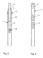
Figur 2 eine teilweise darstellte Draufsicht auf ein Schaftteil des chirurgischen Instruments; -
Figur 3 eine teilweise dargestellte Unteransicht eines Schieberteils des chirurgischen Instruments gemässFigur 1 ; -
Figur 4 eine teilweise dargestellte Seitenansicht eines Ausschnitts aus Schieber und Schaftteil; -
Figur 5 eine vergrössert dargestellte Schnittansicht eines Ausschnitts x aus dem Schaftteil gemässFigur 4 . - Ein erfindungsgemässes chirurgisches Instrument P weist gemäss
Figur 1 ein Schaftteil 1 auf, welches im gezeigten Ausführungsbeispiel einstückig in ein Griffteil 2 übergeht. Auf diesem Schaftteil 1 sitzt ein Schieber 3 auf, der entlang dem Schaftteil 1 bewegbar ist. Bei dieser Bewegung wird ein Maul 4, welches zwischen Schaftteil 1 und Schieber 3 endwärtig ausgebildet ist, geöffnet bzw. geschlossen. Hierbei kann beispielsweise ein Gewebestück ausgestanzt werden. - Die Bewegung des Schiebers 3 wird von einem weiteren Griffteil 5 bewirkt, welches das andere Griffteil 2 durchsetzt und mit diesem über ein Gelenk 6 verbunden ist. An seinem aus dem Griffteil 2 herausragenden Ende ist in dieses Griffteil 5 ein Langloch 7 eingeformt, in das ein Querbolzen 8 eingesetzt ist, so dass hier eine gelenkige Verbindung mit dem Schieber 3 gebildet wird.
- Der Schieber 3 ist mit dem Schaftteil 1 lösbar verbunden. Hierzu ragt vom Schieber 3 gemäss
Figur 4 nach unten eine Nutensteinschiene 9 ab, welche in eine Ausnehmung 10 (siehe auchFiguren 2 und 3 ) in dem Schaftteil 1 einsetzbar ist und nach einem Schiebeweg in Richtung Maul 4 in eine hinterschnittene Nut 11 einfährt. - Um die Nutensteinschiene 9 daran zu hindern, aus der hinterschnittenen Nut 11 nach hinten vom Maul weg herauszugleiten ist eine erfindungsgemässe Rasteinrichtung 12 vorgesehen. Diese wirkt mit einem Langloch 13 im Schieber 3 zusammen. Die Rasteinrichtung 12 durchsetzt im gezeigten Ausführungsbeispiel das Schaftteil 1 im Bereich der hinterschnittenen Nut 11, sie könnte aber auch an anderer Stelle angeordnet sein. Sie weist einen Stift 14 auf, der von einem Knopf 15 betätigt werden kann. Die Betätigung geschieht gegen eine Schraubenfeder 16, die sich in einer Bohrung 17 in dem Schaftteil 1 befindet. Sie stützt sich einerseits gegen eine Wand 18 des Schaftteils 1 oder eine separat eingesetzte Platte und andererseits gegen einen Sprengring 19 ab, welcher dem Stift 14 aufgesetzt ist.
- Die Funktionsweise der vorliegenden Erfindung ist folgende:
- In Ausgangslage sind die beiden Griffteile 2 und 5 über das Gelenk 6, welches beispielsweise durch einen Schraubenbolzen gebildet wird, miteinander verbunden. Sie stützen sich gegenseitig durch zwei Blattfedern 20.1 und 20.2 ab, so dass das Maul 4 in Öffnungslage gehalten wird.
- Schaftteil 1 und Schieber 3 befinden sich ausserhalb der Rastlage, wie dies in
Figur 4 gezeigt ist. Um nun den Schieber 3 mit dem Schaftteil 1 zu verbinden, wird dieser Schieber 3 gegen das Schaftteil 1 bewegt, wobei der aus dem Schaftteil 1 herausragende Stift 14 durch eine Innenfläche 21 des Schiebers 3 weggedrückt wird. Dies geschieht gegen die Kraft der Schraubenfeder 16. Dabei fährt gleichzeitig die Nutensteinschiene 9 in die Ausnehmung 10 hinter der hinterschnittenen Nut 11 ein. In dieser Lage liegt die Innenfläche 21 plan einer Oberfläche 22 des Schaftteils 1 an. - Nunmehr wird mittels des Griffteils 5 der Schieber 3 in Richtung Maul 4 bewegt, wobei die Nutensteinschiene 9 in die hinterschnittene Nut 11 einfährt und die entsprechenden Hinterschneidungen untergreift. Damit ist der Schieber 3 gegenüber dem Schaftteil 1 festgelegt.
- Nach einem weiteren Fahrweg überfährt das Langloch 13 in dem Schieber 3 den Stift 14, so dass dieser hinter einer Steuerkante 23 des Langlochs 13 in dieses einfahren kann. Hierbei entspannt sich die Schraubenfeder 16. Diese Steuerkante 23 bewirkt nun durch ein Anschlagen an dem Stift 14, dass die Spreizwirkung der Blattfeder 20.1 und 20.2 gegen die Griffteile 2 und 5 begrenzt ist. Hierdurch wird verhindert, dass die Nutensteinschiene 9 zu weit sich nach hinten bewegt und dabei unbeabsichtigt aus der hinterschnittenen Nut 11 herausfährt.
- Zum Zerlegen des erfindungsgemässen chirurgischen Instruments wird einfach der Stift 14 durch Ziehen an dem Knopf 15 aus der Rastlage in dem Langloch 13 herausbewegt, so dass nunmehr die Steuerkante 23 den Stift 14 überfahren kann. Nahe einem weiteren Fahrweg des Schiebers 3 gegenüber dem Schaftteil 1 gelangt auch die Nutensteinschiene 9 ausser Eingriff mit der hinterschnittenen Nut 11. Der Schieber 3 kann nun von dem Schaftteil 1 weggeklappt werden. Ist beispielsweise das Langloch 7 nach oben hin offen, kann auch ohne Lösen des Querbolzens 8 der Schieber 3 von dem Griffteil 5 abgenommen werden.
Bezugszeichenliste 1 Schaftteil 34 67 2 Griffteil 35 68 3 Schieber 36 69 4 Maul 37 70 5 Griffteil 38 71 6 Gelenk 39 72 7 Langloch 40 73 8 Querbolzen 41 74 9 Nutensteinschiene 42 75 10 Ausnehmung 43 76 11 Nut 44 77 12 Rasteinrichtung 45 78 13 Langloch 46 79 14 Stift 47 15 Kopf 48 16 Schraubenfeder 49 17 Bohrung 50 18 Wand 51 19 Sprengring 52 20 Blattfeder 53 21 Innenfläche 54 22 Oberfläche 55 23 Steuerkante 56 24 57 25 58 26 59 P Chir. Instrument 27 60 28 61 29 62 30 63 31 64 32 65 33 66
Claims (15)
- Chirurgisches Instrument mit einem Schaftteil (1), dem ein Schieber (3) zugeordnet ist, wobei Schaftteil (1) und Schieber (3) eine lösbare Verbindung eingehen,
dadurch gekennzeichnet,
dass von dem Schaftteil (1) und/oder dem Schieber ein Rastelement (14) abragt, das beim Entlangschieben des Schiebers (3) an dem Schaftteil (1) in einer Ausnehmung (13) des Schiebers (3) und/oder des Schaftteils einfährt. - Instrument nach Anspruch 1, dadurch gekennzeichnet, dass das Rastelement (14) unter dem Druck eines Kraftspeichers (16) in Rastlage gehalten ist.
- Instrument nach Anspruch 2, dadurch gekennzeichnet, dass der Kraftspeicher eine Schraubenfeder (16) ist.
- Instrument nach Anspruch 2 oder 3, dadurch gekennzeichnet, dass der Kraftspeicher in einer Bohrung (17) im Schaftteil (1) und/oder des Schiebers (3) festgelegt ist.
- Instrument nach wenigstens einem der vorhergehenden Ansprüche, dadurch gekennzeichnet, dass das Rastelement einen Stift (14) aufweist, der mit einem Knopf (15) zum Betätigen des Stiftes verbunden ist.
- Instrument nach wenigstens einem der vorhergehenden Ansprüche, dadurch gekennzeichnet, dass das Rastelement (14) eine hinterschnittene Nut (11) in dem Schaftteil (1) durchsetzt.
- Instrument nach Anspruch 6, dadurch gekennzeichnet, dass an die hinterschnittene Nut (11) in dem Schaftteil (1) eine längliche Ausnehmung (10) anschliesst.
- Instrument nach wenigstens einem der vorhergehenden Ansprüche, dadurch gekennzeichnet, dass dem Rastelement (14) eine Ausnehmung (13) in dem Schieber (3), bevorzugt in der Form eines Langlochs, zugeordnet ist.
- Instrument nach wenigstens einem der vorhergehenden Ansprüche, dadurch gekennzeichnet, dass die Ausnehmung (13) in dem Schieber (3) etwa gegenüberliegend der hinterschnittenen Nut (11) vorgesehen ist.
- Instrument nach wenigstens einem der vorhergehenden Ansprüche, dadurch gekennzeichnet, dass an die Ausnehmung (13) in dem Schieber (3) eine Nutensteinschiene (9) anschliesst.
- Instrument nach Anspruch 10, dadurch gekennzeichnet, dass die Nutensteinschiene (9) in etwa gegenüber der Ausnehmung (10) in dem Schaftteil (1) vorgesehen ist.
- Instrument nach wenigstens einem der vorhergehenden Ansprüche, dadurch gekennzeichnet, dass sowohl an den Schaftteil (1) als auch an den Schieber (3) ein Griffteil (2, 5) anschliesst.
- Instrument nach Anspruch 12, dadurch gekennzeichnet, dass die beiden Griffteile (2, 5) gelenkig miteinander verbunden sind.
- Instrument nach Anspruch 12 oder 13, dadurch gekennzeichnet, dass das dem Schieber (3) zugeordnete Griffteil (5) mit diesem eine gelenkige, gegebenenfalls lösbare Verbindung eingeht.
- Verfahren zum Verbessern eines chirurgischen Instruments mit einem Schaftteil (1), dem ein Schieber (3) zugeordnet ist, wobei Schaftteil (1) und Schieber (3) eine Verbindung eingehen, dadurch gekennzeichnet, dass in das Schaftteil (1) und/oder in den Schieber (3) eine Ausnehmung (13) und dieser gegenüberliegend ein Rastelement (14) eingebracht wird, welches mit der Ausnehmung (13) zusammenwirkt.
Applications Claiming Priority (1)
| Application Number | Priority Date | Filing Date | Title |
|---|---|---|---|
| DE102013101594.8A DE102013101594A1 (de) | 2013-02-18 | 2013-02-18 | Chirurgisches Instrument |
Publications (2)
| Publication Number | Publication Date |
|---|---|
| EP2767244A1 true EP2767244A1 (de) | 2014-08-20 |
| EP2767244B1 EP2767244B1 (de) | 2017-04-26 |
Family
ID=50150553
Family Applications (1)
| Application Number | Title | Priority Date | Filing Date |
|---|---|---|---|
| EP14154575.6A Not-in-force EP2767244B1 (de) | 2013-02-18 | 2014-02-11 | Chirurgisches Instrument |
Country Status (3)
| Country | Link |
|---|---|
| US (1) | US20140236204A1 (de) |
| EP (1) | EP2767244B1 (de) |
| DE (1) | DE102013101594A1 (de) |
Families Citing this family (1)
| Publication number | Priority date | Publication date | Assignee | Title |
|---|---|---|---|---|
| DE102015100945A1 (de) * | 2015-01-22 | 2016-07-28 | Dannoritzer Medizintechnik Gmbh & Co. Kg | Handgriffvorrichtung |
Citations (4)
| Publication number | Priority date | Publication date | Assignee | Title |
|---|---|---|---|---|
| DE10320477B3 (de) * | 2003-05-08 | 2004-07-29 | Kapp Chirurgische Instrumente Gmbh | Chirurgisches Instrument |
| DE102006012754A1 (de) * | 2006-03-17 | 2007-09-20 | Heinrich Widmann | Chirurgisches Instrument |
| EP1363542B1 (de) * | 2001-03-01 | 2007-10-31 | Heinrich Widmann | Chirurgisches instrument |
| DE102008034287A1 (de) * | 2008-07-22 | 2010-02-04 | Hebumedical Gmbh | Chirurgisches Instrument |
Family Cites Families (8)
| Publication number | Priority date | Publication date | Assignee | Title |
|---|---|---|---|---|
| DE3166638D1 (en) * | 1980-12-23 | 1984-11-15 | Kontron Ag | Implantable electrode |
| DE8406730U1 (de) * | 1984-03-05 | 1984-04-26 | Waldemar Link (Gmbh & Co), 2000 Hamburg | Chirurgischer Meißel |
| US6200320B1 (en) * | 1989-04-24 | 2001-03-13 | Gary Karlin Michelson | Surgical rongeur |
| DE4316768A1 (de) * | 1993-05-19 | 1994-11-24 | Aesculap Ag | Instrument für chirurgische Zwecke |
| DE19748369C2 (de) | 1997-11-03 | 2003-08-21 | Medi Plus Instr Gmbh & Co Kg | Chirurgisches Schiebeschaftinstrument |
| DE19949422A1 (de) | 1999-10-13 | 2001-04-19 | Tontarra Medizintechnik Gmbh | Chirurgisches Instrument |
| DE29922271U1 (de) | 1999-12-17 | 2000-04-27 | Weinmann GmbH, Chirurgische Instrumente, 78606 Seitingen-Oberflacht | Chirurgisches Schiebeschaftinstrument |
| US20060189995A1 (en) * | 2005-02-22 | 2006-08-24 | Zimmer Spine, Inc. | Rongeur that disassembles for cleaning |
-
2013
- 2013-02-18 DE DE102013101594.8A patent/DE102013101594A1/de not_active Withdrawn
-
2014
- 2014-02-11 EP EP14154575.6A patent/EP2767244B1/de not_active Not-in-force
- 2014-02-17 US US14/181,992 patent/US20140236204A1/en not_active Abandoned
Patent Citations (4)
| Publication number | Priority date | Publication date | Assignee | Title |
|---|---|---|---|---|
| EP1363542B1 (de) * | 2001-03-01 | 2007-10-31 | Heinrich Widmann | Chirurgisches instrument |
| DE10320477B3 (de) * | 2003-05-08 | 2004-07-29 | Kapp Chirurgische Instrumente Gmbh | Chirurgisches Instrument |
| DE102006012754A1 (de) * | 2006-03-17 | 2007-09-20 | Heinrich Widmann | Chirurgisches Instrument |
| DE102008034287A1 (de) * | 2008-07-22 | 2010-02-04 | Hebumedical Gmbh | Chirurgisches Instrument |
Also Published As
| Publication number | Publication date |
|---|---|
| DE102013101594A1 (de) | 2014-09-04 |
| EP2767244B1 (de) | 2017-04-26 |
| US20140236204A1 (en) | 2014-08-21 |
Similar Documents
| Publication | Publication Date | Title |
|---|---|---|
| EP2578171B1 (de) | Chirurgisches Instrument | |
| DE102009037614A1 (de) | Elektrochirurgisches Instrument | |
| WO2008131466A1 (de) | Federpuffer für ein möbel | |
| EP3045641A1 (de) | Dämpfvorrichtung für möbelteile | |
| DE202009002433U1 (de) | Chirurgisches Instrument | |
| DE202011107977U1 (de) | Medizinisches Instrument | |
| DE102007011670A1 (de) | Chirurgische Knochenstanze | |
| DE102011089682B4 (de) | Matrize für eine Stanzvorrichtung, Stanzwerkzeug für eine Stanzvor-richtung mit einer solchen Matrize sowie Verfahren zum Heraus-schneiden von Werkstückteilen aus Werkstücken mit einer entspre-chenden Matrize | |
| EP3153115B1 (de) | Knochenstanze mit unverlierbarem stanzschieber | |
| EP2774509A1 (de) | Vorrichtung zur Lageausrichtung einer Front eines bewegbaren Möbelteils | |
| EP1363542B1 (de) | Chirurgisches instrument | |
| EP2560520B1 (de) | AUSSTOßER ZUM AUSSTOßEN EINES BEWEGBAREN MÖBELTEILS | |
| DE202007006549U1 (de) | Federpuffer für ein Möbel | |
| EP2281482B1 (de) | Ausstoßvorrichtung einer Ausziehführung und Ausziehführung | |
| DE102009056099A1 (de) | Chirurgisches Instrument | |
| DE202014105730U1 (de) | Wandelement eines Möbels und Möbel mit einem solchen Wandelement | |
| DE102009049317B4 (de) | Chirurgisches Instrument | |
| DE102009019123B4 (de) | Chirurgisches Instrument mit Rückstellsystem | |
| EP2767244B1 (de) | Chirurgisches Instrument | |
| DE29500422U1 (de) | Chirurgisches Stanzwerkzeug | |
| DE202009001829U1 (de) | Chirurgisches Schiebeschaftinstrument und Schiebeschaft | |
| EP2926746B1 (de) | Chirurgisches instrument | |
| DE10320477B3 (de) | Chirurgisches Instrument | |
| DE202009001809U1 (de) | Chirurgisches Schiebeschaftinstrument und Schiebeschaft | |
| DE202013008886U1 (de) | Schiebeschaftinstrument |
Legal Events
| Date | Code | Title | Description |
|---|---|---|---|
| PUAI | Public reference made under article 153(3) epc to a published international application that has entered the european phase |
Free format text: ORIGINAL CODE: 0009012 |
|
| 17P | Request for examination filed |
Effective date: 20140211 |
|
| AK | Designated contracting states |
Kind code of ref document: A1 Designated state(s): AL AT BE BG CH CY CZ DE DK EE ES FI FR GB GR HR HU IE IS IT LI LT LU LV MC MK MT NL NO PL PT RO RS SE SI SK SM TR |
|
| AX | Request for extension of the european patent |
Extension state: BA ME |
|
| R17P | Request for examination filed (corrected) |
Effective date: 20150217 |
|
| RBV | Designated contracting states (corrected) |
Designated state(s): AL AT BE BG CH CY CZ DE DK EE ES FI FR GB GR HR HU IE IS IT LI LT LU LV MC MK MT NL NO PL PT RO RS SE SI SK SM TR |
|
| GRAP | Despatch of communication of intention to grant a patent |
Free format text: ORIGINAL CODE: EPIDOSNIGR1 |
|
| RIC1 | Information provided on ipc code assigned before grant |
Ipc: A61B 17/16 20060101AFI20161025BHEP |
|
| INTG | Intention to grant announced |
Effective date: 20161122 |
|
| GRAS | Grant fee paid |
Free format text: ORIGINAL CODE: EPIDOSNIGR3 |
|
| GRAA | (expected) grant |
Free format text: ORIGINAL CODE: 0009210 |
|
| AK | Designated contracting states |
Kind code of ref document: B1 Designated state(s): AL AT BE BG CH CY CZ DE DK EE ES FI FR GB GR HR HU IE IS IT LI LT LU LV MC MK MT NL NO PL PT RO RS SE SI SK SM TR |
|
| REG | Reference to a national code |
Ref country code: GB Ref legal event code: FG4D Free format text: NOT ENGLISH |
|
| REG | Reference to a national code |
Ref country code: CH Ref legal event code: EP |
|
| REG | Reference to a national code |
Ref country code: AT Ref legal event code: REF Ref document number: 887184 Country of ref document: AT Kind code of ref document: T Effective date: 20170515 |
|
| REG | Reference to a national code |
Ref country code: IE Ref legal event code: FG4D Free format text: LANGUAGE OF EP DOCUMENT: GERMAN |
|
| REG | Reference to a national code |
Ref country code: DE Ref legal event code: R096 Ref document number: 502014003520 Country of ref document: DE |
|
| REG | Reference to a national code |
Ref country code: CH Ref legal event code: NV Representative=s name: ARIE WUBBEN C/O MEDIPACK AG, CH |
|
| REG | Reference to a national code |
Ref country code: NL Ref legal event code: MP Effective date: 20170426 |
|
| REG | Reference to a national code |
Ref country code: LT Ref legal event code: MG4D |
|
| REG | Reference to a national code |
Ref country code: CH Ref legal event code: PCOW Free format text: NEW ADDRESS: LANGES GEWAND 7, 78604 RIETHEIM-WEILHEIM (DE) |
|
| PG25 | Lapsed in a contracting state [announced via postgrant information from national office to epo] |
Ref country code: NL Free format text: LAPSE BECAUSE OF FAILURE TO SUBMIT A TRANSLATION OF THE DESCRIPTION OR TO PAY THE FEE WITHIN THE PRESCRIBED TIME-LIMIT Effective date: 20170426 |
|
| PG25 | Lapsed in a contracting state [announced via postgrant information from national office to epo] |
Ref country code: ES Free format text: LAPSE BECAUSE OF FAILURE TO SUBMIT A TRANSLATION OF THE DESCRIPTION OR TO PAY THE FEE WITHIN THE PRESCRIBED TIME-LIMIT Effective date: 20170426 Ref country code: LT Free format text: LAPSE BECAUSE OF FAILURE TO SUBMIT A TRANSLATION OF THE DESCRIPTION OR TO PAY THE FEE WITHIN THE PRESCRIBED TIME-LIMIT Effective date: 20170426 Ref country code: HR Free format text: LAPSE BECAUSE OF FAILURE TO SUBMIT A TRANSLATION OF THE DESCRIPTION OR TO PAY THE FEE WITHIN THE PRESCRIBED TIME-LIMIT Effective date: 20170426 Ref country code: FI Free format text: LAPSE BECAUSE OF FAILURE TO SUBMIT A TRANSLATION OF THE DESCRIPTION OR TO PAY THE FEE WITHIN THE PRESCRIBED TIME-LIMIT Effective date: 20170426 Ref country code: GR Free format text: LAPSE BECAUSE OF FAILURE TO SUBMIT A TRANSLATION OF THE DESCRIPTION OR TO PAY THE FEE WITHIN THE PRESCRIBED TIME-LIMIT Effective date: 20170727 Ref country code: NO Free format text: LAPSE BECAUSE OF FAILURE TO SUBMIT A TRANSLATION OF THE DESCRIPTION OR TO PAY THE FEE WITHIN THE PRESCRIBED TIME-LIMIT Effective date: 20170726 |
|
| REG | Reference to a national code |
Ref country code: DE Ref legal event code: R082 Ref document number: 502014003520 Country of ref document: DE Representative=s name: PATENTANWAELTE UND RECHTSANWALT WEISS, ARAT & , DE Ref country code: DE Ref legal event code: R081 Ref document number: 502014003520 Country of ref document: DE Owner name: LT TECHNOLOGIES GMBH & CO KG, DE Free format text: FORMER OWNER: LT TECHNOLOGIES GMBH & CO KG, 78573 WURMLINGEN, DE |
|
| PG25 | Lapsed in a contracting state [announced via postgrant information from national office to epo] |
Ref country code: IS Free format text: LAPSE BECAUSE OF FAILURE TO SUBMIT A TRANSLATION OF THE DESCRIPTION OR TO PAY THE FEE WITHIN THE PRESCRIBED TIME-LIMIT Effective date: 20170826 Ref country code: LV Free format text: LAPSE BECAUSE OF FAILURE TO SUBMIT A TRANSLATION OF THE DESCRIPTION OR TO PAY THE FEE WITHIN THE PRESCRIBED TIME-LIMIT Effective date: 20170426 Ref country code: SE Free format text: LAPSE BECAUSE OF FAILURE TO SUBMIT A TRANSLATION OF THE DESCRIPTION OR TO PAY THE FEE WITHIN THE PRESCRIBED TIME-LIMIT Effective date: 20170426 Ref country code: RS Free format text: LAPSE BECAUSE OF FAILURE TO SUBMIT A TRANSLATION OF THE DESCRIPTION OR TO PAY THE FEE WITHIN THE PRESCRIBED TIME-LIMIT Effective date: 20170426 Ref country code: PL Free format text: LAPSE BECAUSE OF FAILURE TO SUBMIT A TRANSLATION OF THE DESCRIPTION OR TO PAY THE FEE WITHIN THE PRESCRIBED TIME-LIMIT Effective date: 20170426 Ref country code: BG Free format text: LAPSE BECAUSE OF FAILURE TO SUBMIT A TRANSLATION OF THE DESCRIPTION OR TO PAY THE FEE WITHIN THE PRESCRIBED TIME-LIMIT Effective date: 20170726 |
|
| REG | Reference to a national code |
Ref country code: DE Ref legal event code: R097 Ref document number: 502014003520 Country of ref document: DE |
|
| PG25 | Lapsed in a contracting state [announced via postgrant information from national office to epo] |
Ref country code: RO Free format text: LAPSE BECAUSE OF FAILURE TO SUBMIT A TRANSLATION OF THE DESCRIPTION OR TO PAY THE FEE WITHIN THE PRESCRIBED TIME-LIMIT Effective date: 20170426 Ref country code: SK Free format text: LAPSE BECAUSE OF FAILURE TO SUBMIT A TRANSLATION OF THE DESCRIPTION OR TO PAY THE FEE WITHIN THE PRESCRIBED TIME-LIMIT Effective date: 20170426 Ref country code: EE Free format text: LAPSE BECAUSE OF FAILURE TO SUBMIT A TRANSLATION OF THE DESCRIPTION OR TO PAY THE FEE WITHIN THE PRESCRIBED TIME-LIMIT Effective date: 20170426 Ref country code: CZ Free format text: LAPSE BECAUSE OF FAILURE TO SUBMIT A TRANSLATION OF THE DESCRIPTION OR TO PAY THE FEE WITHIN THE PRESCRIBED TIME-LIMIT Effective date: 20170426 Ref country code: DK Free format text: LAPSE BECAUSE OF FAILURE TO SUBMIT A TRANSLATION OF THE DESCRIPTION OR TO PAY THE FEE WITHIN THE PRESCRIBED TIME-LIMIT Effective date: 20170426 |
|
| PG25 | Lapsed in a contracting state [announced via postgrant information from national office to epo] |
Ref country code: IT Free format text: LAPSE BECAUSE OF FAILURE TO SUBMIT A TRANSLATION OF THE DESCRIPTION OR TO PAY THE FEE WITHIN THE PRESCRIBED TIME-LIMIT Effective date: 20170426 Ref country code: SM Free format text: LAPSE BECAUSE OF FAILURE TO SUBMIT A TRANSLATION OF THE DESCRIPTION OR TO PAY THE FEE WITHIN THE PRESCRIBED TIME-LIMIT Effective date: 20170426 |
|
| PLBE | No opposition filed within time limit |
Free format text: ORIGINAL CODE: 0009261 |
|
| STAA | Information on the status of an ep patent application or granted ep patent |
Free format text: STATUS: NO OPPOSITION FILED WITHIN TIME LIMIT |
|
| 26N | No opposition filed |
Effective date: 20180129 |
|
| PGFP | Annual fee paid to national office [announced via postgrant information from national office to epo] |
Ref country code: CH Payment date: 20180216 Year of fee payment: 5 |
|
| PG25 | Lapsed in a contracting state [announced via postgrant information from national office to epo] |
Ref country code: SI Free format text: LAPSE BECAUSE OF FAILURE TO SUBMIT A TRANSLATION OF THE DESCRIPTION OR TO PAY THE FEE WITHIN THE PRESCRIBED TIME-LIMIT Effective date: 20170426 |
|
| PGFP | Annual fee paid to national office [announced via postgrant information from national office to epo] |
Ref country code: DE Payment date: 20180425 Year of fee payment: 5 |
|
| PG25 | Lapsed in a contracting state [announced via postgrant information from national office to epo] |
Ref country code: MT Free format text: LAPSE BECAUSE OF FAILURE TO SUBMIT A TRANSLATION OF THE DESCRIPTION OR TO PAY THE FEE WITHIN THE PRESCRIBED TIME-LIMIT Effective date: 20170426 Ref country code: MC Free format text: LAPSE BECAUSE OF FAILURE TO SUBMIT A TRANSLATION OF THE DESCRIPTION OR TO PAY THE FEE WITHIN THE PRESCRIBED TIME-LIMIT Effective date: 20170426 |
|
| GBPC | Gb: european patent ceased through non-payment of renewal fee |
Effective date: 20180211 |
|
| REG | Reference to a national code |
Ref country code: IE Ref legal event code: MM4A |
|
| REG | Reference to a national code |
Ref country code: BE Ref legal event code: MM Effective date: 20180228 |
|
| PG25 | Lapsed in a contracting state [announced via postgrant information from national office to epo] |
Ref country code: LU Free format text: LAPSE BECAUSE OF NON-PAYMENT OF DUE FEES Effective date: 20180211 |
|
| REG | Reference to a national code |
Ref country code: FR Ref legal event code: ST Effective date: 20181031 |
|
| PG25 | Lapsed in a contracting state [announced via postgrant information from national office to epo] |
Ref country code: IE Free format text: LAPSE BECAUSE OF NON-PAYMENT OF DUE FEES Effective date: 20180211 |
|
| PG25 | Lapsed in a contracting state [announced via postgrant information from national office to epo] |
Ref country code: GB Free format text: LAPSE BECAUSE OF NON-PAYMENT OF DUE FEES Effective date: 20180211 Ref country code: BE Free format text: LAPSE BECAUSE OF NON-PAYMENT OF DUE FEES Effective date: 20180228 Ref country code: FR Free format text: LAPSE BECAUSE OF NON-PAYMENT OF DUE FEES Effective date: 20180228 |
|
| REG | Reference to a national code |
Ref country code: DE Ref legal event code: R119 Ref document number: 502014003520 Country of ref document: DE |
|
| REG | Reference to a national code |
Ref country code: CH Ref legal event code: PL |
|
| PG25 | Lapsed in a contracting state [announced via postgrant information from national office to epo] |
Ref country code: LI Free format text: LAPSE BECAUSE OF NON-PAYMENT OF DUE FEES Effective date: 20190228 Ref country code: CH Free format text: LAPSE BECAUSE OF NON-PAYMENT OF DUE FEES Effective date: 20190228 |
|
| PG25 | Lapsed in a contracting state [announced via postgrant information from national office to epo] |
Ref country code: DE Free format text: LAPSE BECAUSE OF NON-PAYMENT OF DUE FEES Effective date: 20190903 |
|
| PG25 | Lapsed in a contracting state [announced via postgrant information from national office to epo] |
Ref country code: TR Free format text: LAPSE BECAUSE OF FAILURE TO SUBMIT A TRANSLATION OF THE DESCRIPTION OR TO PAY THE FEE WITHIN THE PRESCRIBED TIME-LIMIT Effective date: 20170426 |
|
| REG | Reference to a national code |
Ref country code: AT Ref legal event code: MM01 Ref document number: 887184 Country of ref document: AT Kind code of ref document: T Effective date: 20190211 |
|
| PG25 | Lapsed in a contracting state [announced via postgrant information from national office to epo] |
Ref country code: AT Free format text: LAPSE BECAUSE OF NON-PAYMENT OF DUE FEES Effective date: 20190211 |
|
| PG25 | Lapsed in a contracting state [announced via postgrant information from national office to epo] |
Ref country code: HU Free format text: LAPSE BECAUSE OF FAILURE TO SUBMIT A TRANSLATION OF THE DESCRIPTION OR TO PAY THE FEE WITHIN THE PRESCRIBED TIME-LIMIT; INVALID AB INITIO Effective date: 20140211 Ref country code: PT Free format text: LAPSE BECAUSE OF FAILURE TO SUBMIT A TRANSLATION OF THE DESCRIPTION OR TO PAY THE FEE WITHIN THE PRESCRIBED TIME-LIMIT Effective date: 20170426 |
|
| PG25 | Lapsed in a contracting state [announced via postgrant information from national office to epo] |
Ref country code: CY Free format text: LAPSE BECAUSE OF FAILURE TO SUBMIT A TRANSLATION OF THE DESCRIPTION OR TO PAY THE FEE WITHIN THE PRESCRIBED TIME-LIMIT Effective date: 20170426 Ref country code: MK Free format text: LAPSE BECAUSE OF NON-PAYMENT OF DUE FEES Effective date: 20170426 |
|
| PG25 | Lapsed in a contracting state [announced via postgrant information from national office to epo] |
Ref country code: AL Free format text: LAPSE BECAUSE OF FAILURE TO SUBMIT A TRANSLATION OF THE DESCRIPTION OR TO PAY THE FEE WITHIN THE PRESCRIBED TIME-LIMIT Effective date: 20170426 |