EP2767177B2 - Method, mechanism and apparatus for momentary compression of filter material - Google Patents
Method, mechanism and apparatus for momentary compression of filter material Download PDFInfo
- Publication number
- EP2767177B2 EP2767177B2 EP14153194.7A EP14153194A EP2767177B2 EP 2767177 B2 EP2767177 B2 EP 2767177B2 EP 14153194 A EP14153194 A EP 14153194A EP 2767177 B2 EP2767177 B2 EP 2767177B2
- Authority
- EP
- European Patent Office
- Prior art keywords
- filter material
- rotary compressing
- rotary
- members
- wrapper
- Prior art date
- Legal status (The legal status is an assumption and is not a legal conclusion. Google has not performed a legal analysis and makes no representation as to the accuracy of the status listed.)
- Active
Links
- 239000000463 material Substances 0.000 title claims description 70
- 230000006835 compression Effects 0.000 title claims description 18
- 238000007906 compression Methods 0.000 title claims description 18
- 238000000034 method Methods 0.000 title claims description 15
- 239000000853 adhesive Substances 0.000 claims description 13
- 230000001070 adhesive effect Effects 0.000 claims description 13
- 238000004519 manufacturing process Methods 0.000 claims description 11
- 230000006837 decompression Effects 0.000 claims description 8
- 238000003825 pressing Methods 0.000 claims description 6
- 241000208125 Nicotiana Species 0.000 claims description 4
- 235000002637 Nicotiana tabacum Nutrition 0.000 claims description 4
- 235000019504 cigarettes Nutrition 0.000 description 5
- 238000005520 cutting process Methods 0.000 description 3
- 239000012634 fragment Substances 0.000 description 3
- 238000004026 adhesive bonding Methods 0.000 description 2
- QTBSBXVTEAMEQO-UHFFFAOYSA-M Acetate Chemical compound CC([O-])=O QTBSBXVTEAMEQO-UHFFFAOYSA-M 0.000 description 1
- 230000000694 effects Effects 0.000 description 1
- 238000001914 filtration Methods 0.000 description 1
- 230000001360 synchronised effect Effects 0.000 description 1
Images


Classifications
-
- A—HUMAN NECESSITIES
- A24—TOBACCO; CIGARS; CIGARETTES; SIMULATED SMOKING DEVICES; SMOKERS' REQUISITES
- A24D—CIGARS; CIGARETTES; TOBACCO SMOKE FILTERS; MOUTHPIECES FOR CIGARS OR CIGARETTES; MANUFACTURE OF TOBACCO SMOKE FILTERS OR MOUTHPIECES
- A24D3/00—Tobacco smoke filters, e.g. filter-tips, filtering inserts; Filters specially adapted for simulated smoking devices; Mouthpieces for cigars or cigarettes
- A24D3/02—Manufacture of tobacco smoke filters
- A24D3/0229—Filter rod forming processes
- A24D3/0241—Filter rod forming processes by compacting particulated materials
-
- A—HUMAN NECESSITIES
- A24—TOBACCO; CIGARS; CIGARETTES; SIMULATED SMOKING DEVICES; SMOKERS' REQUISITES
- A24D—CIGARS; CIGARETTES; TOBACCO SMOKE FILTERS; MOUTHPIECES FOR CIGARS OR CIGARETTES; MANUFACTURE OF TOBACCO SMOKE FILTERS OR MOUTHPIECES
- A24D3/00—Tobacco smoke filters, e.g. filter-tips, filtering inserts; Filters specially adapted for simulated smoking devices; Mouthpieces for cigars or cigarettes
- A24D3/02—Manufacture of tobacco smoke filters
- A24D3/025—Final operations, i.e. after the filter rod forming process
- A24D3/0262—Filter extremity shaping and compacting means
-
- A—HUMAN NECESSITIES
- A24—TOBACCO; CIGARS; CIGARETTES; SIMULATED SMOKING DEVICES; SMOKERS' REQUISITES
- A24D—CIGARS; CIGARETTES; TOBACCO SMOKE FILTERS; MOUTHPIECES FOR CIGARS OR CIGARETTES; MANUFACTURE OF TOBACCO SMOKE FILTERS OR MOUTHPIECES
- A24D3/00—Tobacco smoke filters, e.g. filter-tips, filtering inserts; Filters specially adapted for simulated smoking devices; Mouthpieces for cigars or cigarettes
- A24D3/02—Manufacture of tobacco smoke filters
- A24D3/0275—Manufacture of tobacco smoke filters for filters with special features
- A24D3/0287—Manufacture of tobacco smoke filters for filters with special features for composite filters
Definitions
- the object of the invention is a method and an apparatus for a momentary compression of a filter material used to manufacture tobacco industry products.
- filters In the tobacco industry, cigarettes provided with filters are manufactured, whereas the filters can be made of one kind of material or can be composed of multiple materials having different physical and filtering characteristics.
- the filter material in a continuous form, for example acetate, is cut into rods and applied to the cigarettes.
- filters manufactured of several concentrically arranged filter material layers are known. Filters having several segments of different materials are more and more frequently used in the cigarettes manufactured in present times.
- Machines for manufacturing multi-segment filter rods of continuous multi-segment filter rods are known in the prior art. Such machines combine the segments delivered from multiple feeding devices, whereas the segments are formed by cutting filter rods transferred for example on a drum conveyor using a cutting head provided with rotary knives.
- a very significant aspect of the production of filter rods of different known kinds is the quality of segment wrapping with a wrapper.
- the quality is determined by both the deformation of the wrapper in the region of an adhesive seam and the filling of the wrapper with the filter material.
- the problem to be solved by present invention is to develop an improved apparatus and a method for compression of the filter material.
- the gist of the invention is a method according to Claim 1.
- a method according to the invention is characterised in that the filter material is gradually compressed by means of a set of multiple rotary compressing members acting on the material being compressed with a different force.
- a method according to the invention characterised in that the force exerted by successive rotary compressing members on the filter material is increasing.
- a method according to the invention characterised in that the force exerted on the filter material is directed in a vertical direction.
- a method according to the invention characterised in that the force exerted on the filter material is directed at an angle to the vertical direction.
- the gist of the invention is also an apparatus according to Claim 6.
- an apparatus according to the invention is characterised in that it comprises two rotary compressing members.
- An apparatus according to the invention is characterised in that it comprises three rotary compressing members.
- An apparatus is characterised in that the last rotary compressing member, counting in the direction of movement of the filter material, has a smaller working width than the preceding compressing members.
- An apparatus according to the invention is characterised in that it is adapted to the adjustment of position of the rotary compressing members in at least one axis, preferably in all axes.
- An apparatus is characterised in that it is adapted to the adjustment of the angle between an axis of the linear movement of the filter material and a line of compression of the compressing mechanism, in particular the line determined by the centres of rotation of the rotary compressing members.
- An apparatus according to the invention is characterised in that the rotary compressing member is a compressing roller with a cylindrical working surface.
- An apparatus according to the invention is characterised in that the rotary compressing member is a compressing roller with a conical working surface.
- An apparatus according to the invention is characterised in that the rotary compressing member is a compressing roller with an oval working surface.
- An advantage of the method and the apparatus according to the invention is an effective operation with a low-cost and simple embodiment of the solution according to the invention.
- the solution according to the invention is, in addition, free of drawbacks of solutions known in the prior art, i.e. it does not heat up during the operation, and it does not cause material damage either.
- the compressing members roll on the surface of the filter material differently from the solutions known in the prior art where the effect of sliding of the pressing bars on the filter material occurred.
- FIG. 1 diagrammatically shows a fragment of a machine for manufacturing multi-segment rods.
- a delivery unit 101 delivers filter segments S prepared in a known way onto a conveyor 102, whereas onto its surface a wrapper 103 is placed.
- the wrapper 103 is wrapped in a known way around the segments and glued, whereas the adhesive is delivered from an adhesive applying apparatus 104 and an adhesive seam is heated up by a heater 105.
- a multi-segment continuous rod CR formed in such a way is transferred further and is cut into filter rods FR by means of a known cutting head 106 provided with knives 107.
- Typical members supporting and guiding the endless rod CR and the filter rods FR were omitted in the drawing.
- An apparatus for a momentary compression of the filter material constitutes a part of a machine for manufacturing rods of the filter material. It comprises members for guiding the wrapper and the filter material, and a compressing mechanism 11 a fragment of which was shown in Fig. 2 .
- the compressing mechanism 11 is situated above the moving filter material, for example in the form of segments S, whereas the wrapper into which the segments are wrapped was not shown.
- An example mechanism comprises three rotary compressing members 10 situated one after another, whereas in the embodiment shown the centres of the compressing members 10 lying on the axes of rotation T of the compressing members are situated on one line 12. Through the lowest positioned points, which press the material to the highest degree, a compression line 13 on the circumferential surfaces of the rotary members 10 was drawn.
- the compression line 13 will be parallel to a line 12 going through the centres of the rotary members 10.
- the rotary members 10 can have different diameters, whereas the compression line defined by the lowest positioned points can be inclined relative to the axis SA of the filter material S at an angle ⁇ between 1° and 5°, preferably the inclination is between 2° and 3° depending on the filter material.
- An inclination of the compression line ensures that successive rotary compressing members 10 act on the filter material with an increased force. If different diameters of the rotary members 10 are used, the compression line 13 is a broken line.
- Fig. 3 shows a compressing mechanism 11 for a momentary compression of the filter material in a top view.
- a wrapper 14 into which the segments S are wrapped can be seen here, whereas its edges were marked with the markings 15 and 16.
- an adhesive nozzle 17 of an adhesive applying apparatus, from which the adhesive is delivered onto the wrapper 14 on the edge 15, is shown in simplified representation.
- Three rotary compressing members 10 can be seen in the compressing mechanism 11 shown, whereas the last rotary compressing member 10A has a smaller width g2 than a width g1 of the preceding compressing members 10.
- the rotary compressing members 10, 10A are rotatably mounted in a body 18 by means of bearings 19.
- the rotary compressing members are set in rotational motion by the filter material.
- a torque coming from the forces of friction between the filter material and the surface of compressing members acts on each of the compressing members.
- they are driven by a separate drive mechanically or electronically synchronised with the drive of the conveyor 102 ( Fig. 1 ) so that no slide between the circumferential surface of the rotary members 10 and the surface of the filter material S occurs.
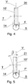
- a rotary compressing member 10' rotating around the axis T shown in Fig. 4 has a circumferential surface 20 in the cylindrical form and during the operation of the mechanism exerts a force F on a continuous or segmental filter material S partly wrapped into the wrapper 14, whereas the force F is directed in a vertical direction V and causes horizontal depression of the filter material.
- the rotary compressing member 10" rotating around the axis T shown in Fig. 5 has a circumferential surface 21 in the conical form and during the operation exerts a force F' on the continuous or segmental filter material S partly wrapped into the wrapper 14, whereas the force F' is directed at an angle ⁇ to the vertical direction V and causes inclined depression on the surface of the filter material.
- the angle ⁇ is between 5° and 30°. Conducted tests showed that even more preferably the angle ⁇ amounts between 15° and 20°.
- a rotary compressing member 10'" rotating around the axis T shown in Fig. 6 has an oval circumferential surface 22 and during the operation exerts a force F" on a continuous or segmental filter material S partly wrapped into the wrapper 14, whereas the force F" is directed at an angle ⁇ to the vertical direction V and causes inclined concave depression of the filter material.
- the position of the compressing mechanism can be selected according to the filter material and the manufacturer's requirements.
- the position of the compressing mechanism can be determined in a typical way in the directions of three axes X, Y and Z ( Figs. 2 and 3 ).
- the angular position of the compressing mechanism can be determined so as to select the value of the angle ⁇ of the compression line of the mechanism relative to the axis of the filter material according to the kind of the filter material.
- the filter material S in the form of segments or in the continuous form is compressed by means of the compressing mechanism 11 in order to reduce the cross-section of the filter material.
- the depression and the reduction of the cross-section caused by the compression makes it possible that wrapping of the wrapper in order to obtain a cylindrical sleeve around the filter material takes place without the need of a simultaneous compression of the wrapped material.
- the wrapper is formed in the cylindrical shape and is glued. A decompression takes place during the wrapping and it finally ends after forming a sleeve of the wrapper. Fig.
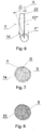
- FIG. 7 shows a section of an endless filter rod during the decompression of the filter material S; a certain space P not yet filled with the filter material exists within the endless rod section, whereas the wrapper has already been formed, and the adhesive seam G has already been made.
- Fig. 8 shows a section of an endless filter rod after the decompression of the filter material S.
- a compressing mechanism 11' according to the invention can also be embodied using an intermediate pressing member 25 ( Fig. 9 ) between the rotary compressing members 10 and the filter material S, for example in the form of a strip or a tape.
- the working surface of the intermediate pressing member 25 can be shaped in any way. The use of an intermediate pressing member does not influence the effectiveness of operation of the mechanism according to the invention.
- An advantage of the method according to the invention is that the final decompression of the filter material takes place after forming and gluing the wrapper, which allows obtaining better filling of the wrapper.
Description
- The object of the invention is a method and an apparatus for a momentary compression of a filter material used to manufacture tobacco industry products.
- In the tobacco industry, cigarettes provided with filters are manufactured, whereas the filters can be made of one kind of material or can be composed of multiple materials having different physical and filtering characteristics. The filter material in a continuous form, for example acetate, is cut into rods and applied to the cigarettes. In addition, filters manufactured of several concentrically arranged filter material layers are known. Filters having several segments of different materials are more and more frequently used in the cigarettes manufactured in present times. Machines for manufacturing multi-segment filter rods of continuous multi-segment filter rods are known in the prior art. Such machines combine the segments delivered from multiple feeding devices, whereas the segments are formed by cutting filter rods transferred for example on a drum conveyor using a cutting head provided with rotary knives. Individual segments are combined, depending on the apparatus, next to one another on a drum conveyor or one after another on a linear conveyor in order to finally form a linearly moving continuous multi-segment rod being cut into individual multi-segment rods. At the further stages of the cigarette manufacturing process the multi-segment rods are cut into individual multi-segment filters applied to individual cigarettes.
- A very significant aspect of the production of filter rods of different known kinds is the quality of segment wrapping with a wrapper. The quality is determined by both the deformation of the wrapper in the region of an adhesive seam and the filling of the wrapper with the filter material.
- Members for compression in the form of immovable pressing bars which heat up during the operation and lead to material damage are known in the prior art. The
US patent 3,716,443 disclosed an apparatus for manufacturing filter rods of a continuous filter material wherein a member for forming an endless filter rod was used, whereas such member is cooled by means of compressed air. Due to the use of compressed air a thin layer reducing the friction between the filter material and the guiding members is formed. - The problem to be solved by present invention is to develop an improved apparatus and a method for compression of the filter material.
- The gist of the invention is a method according to Claim 1.
- A method according to the invention is characterised in that the filter material is gradually compressed by means of a set of multiple rotary compressing members acting on the material being compressed with a different force.
- A method according to the invention characterised in that the force exerted by successive rotary compressing members on the filter material is increasing.
- A method according to the invention characterised in that the force exerted on the filter material is directed in a vertical direction.
- A method according to the invention characterised in that the force exerted on the filter material is directed at an angle to the vertical direction.
- The gist of the invention is also an apparatus according to Claim 6.
- Furthermore, an apparatus according to the invention is characterised in that it comprises two rotary compressing members.
- An apparatus according to the invention is characterised in that it comprises three rotary compressing members.
- An apparatus according to the invention is characterised in that the last rotary compressing member, counting in the direction of movement of the filter material, has a smaller working width than the preceding compressing members.
- An apparatus according to the invention is characterised in that it is adapted to the adjustment of position of the rotary compressing members in at least one axis, preferably in all axes.
- An apparatus according to the invention is characterised in that it is adapted to the adjustment of the angle between an axis of the linear movement of the filter material and a line of compression of the compressing mechanism, in particular the line determined by the centres of rotation of the rotary compressing members.
- An apparatus according to the invention is characterised in that the rotary compressing member is a compressing roller with a cylindrical working surface.
- An apparatus according to the invention is characterised in that the rotary compressing member is a compressing roller with a conical working surface.
- An apparatus according to the invention is characterised in that the rotary compressing member is a compressing roller with an oval working surface.
- An advantage of the method and the apparatus according to the invention is an effective operation with a low-cost and simple embodiment of the solution according to the invention. The solution according to the invention is, in addition, free of drawbacks of solutions known in the prior art, i.e. it does not heat up during the operation, and it does not cause material damage either. The compressing members roll on the surface of the filter material differently from the solutions known in the prior art where the effect of sliding of the pressing bars on the filter material occurred.
- The object of the inventions was shown in detail in a preferred embodiment in a drawing in which:
- Fig. 1
- diagrammatically shows a fragment of a machine for manufacturing multi-segment rods,
- Fig. 2
- shows a compressing mechanism in a front view,
- Fig. 3
- shows a compressing mechanism in a top view,
- Fig. 4
- shows an embodiment of a rotary compressing member,
- Fig. 5
- shows another embodiment of a rotary compressing member,
- Fig. 6
- shows another embodiment of a rotary compressing member,
- Fig. 7
- shows a section of a continuous filter rod during material decompression,
- Fig. 8
- shows a section of a continuous filter rod after material decompression,
- Fig. 9
- shows an alternative embodiment of the compressing mechanism,
-
Fig. 1 diagrammatically shows a fragment of a machine for manufacturing multi-segment rods. Adelivery unit 101 delivers filter segments S prepared in a known way onto aconveyor 102, whereas onto its surface awrapper 103 is placed. During the transfer of segments on theconveyor 102 thewrapper 103 is wrapped in a known way around the segments and glued, whereas the adhesive is delivered from anadhesive applying apparatus 104 and an adhesive seam is heated up by aheater 105. A multi-segment continuous rod CR formed in such a way is transferred further and is cut into filter rods FR by means of a knowncutting head 106 provided withknives 107. Typical members supporting and guiding the endless rod CR and the filter rods FR were omitted in the drawing. - An apparatus for a momentary compression of the filter material constitutes a part of a machine for manufacturing rods of the filter material. It comprises members for guiding the wrapper and the filter material, and a compressing mechanism 11 a fragment of which was shown in
Fig. 2 . Thecompressing mechanism 11 is situated above the moving filter material, for example in the form of segments S, whereas the wrapper into which the segments are wrapped was not shown. An example mechanism comprises three rotary compressingmembers 10 situated one after another, whereas in the embodiment shown the centres of thecompressing members 10 lying on the axes of rotation T of the compressing members are situated on oneline 12. Through the lowest positioned points, which press the material to the highest degree, acompression line 13 on the circumferential surfaces of therotary members 10 was drawn. For therotary members 10 with equal diameters thecompression line 13 will be parallel to aline 12 going through the centres of therotary members 10. Therotary members 10 can have different diameters, whereas the compression line defined by the lowest positioned points can be inclined relative to the axis SA of the filter material S at an angle α between 1° and 5°, preferably the inclination is between 2° and 3° depending on the filter material. An inclination of the compression line ensures that successive rotary compressingmembers 10 act on the filter material with an increased force. If different diameters of therotary members 10 are used, thecompression line 13 is a broken line. -
Fig. 3 shows acompressing mechanism 11 for a momentary compression of the filter material in a top view. Awrapper 14 into which the segments S are wrapped can be seen here, whereas its edges were marked with themarkings adhesive nozzle 17 of an adhesive applying apparatus, from which the adhesive is delivered onto thewrapper 14 on theedge 15, is shown in simplified representation. Threerotary compressing members 10 can be seen in thecompressing mechanism 11 shown, whereas the lastrotary compressing member 10A has a smaller width g2 than a width g1 of the preceding compressingmembers 10. Therotary compressing members body 18 by means ofbearings 19. The rotary compressing members are set in rotational motion by the filter material. A torque coming from the forces of friction between the filter material and the surface of compressing members acts on each of the compressing members. However, a solution is also possible wherein they are driven by a separate drive mechanically or electronically synchronised with the drive of the conveyor 102 (Fig. 1 ) so that no slide between the circumferential surface of therotary members 10 and the surface of the filter material S occurs. - The embodiments of rotary compressing members are described below. A rotary compressing member 10' rotating around the axis T shown in
Fig. 4 has acircumferential surface 20 in the cylindrical form and during the operation of the mechanism exerts a force F on a continuous or segmental filter material S partly wrapped into thewrapper 14, whereas the force F is directed in a vertical direction V and causes horizontal depression of the filter material. Therotary compressing member 10" rotating around the axis T shown inFig. 5 has acircumferential surface 21 in the conical form and during the operation exerts a force F' on the continuous or segmental filter material S partly wrapped into thewrapper 14, whereas the force F' is directed at an angle β to the vertical direction V and causes inclined depression on the surface of the filter material. Preferably the angle β is between 5° and 30°. Conducted tests showed that even more preferably the angle β amounts between 15° and 20°. A rotary compressing member 10'" rotating around the axis T shown inFig. 6 has an ovalcircumferential surface 22 and during the operation exerts a force F" on a continuous or segmental filter material S partly wrapped into thewrapper 14, whereas the force F" is directed at an angle β to the vertical direction V and causes inclined concave depression of the filter material. - The position of the compressing mechanism can be selected according to the filter material and the manufacturer's requirements. The position of the compressing mechanism can be determined in a typical way in the directions of three axes X, Y and Z (
Figs. 2 and 3 ). In addition, the angular position of the compressing mechanism can be determined so as to select the value of the angle α of the compression line of the mechanism relative to the axis of the filter material according to the kind of the filter material. - During the manufacture of filter rods FR, before gluing the
wrapper 14, the filter material S in the form of segments or in the continuous form is compressed by means of thecompressing mechanism 11 in order to reduce the cross-section of the filter material. The depression and the reduction of the cross-section caused by the compression makes it possible that wrapping of the wrapper in order to obtain a cylindrical sleeve around the filter material takes place without the need of a simultaneous compression of the wrapped material. The wrapper is formed in the cylindrical shape and is glued. A decompression takes place during the wrapping and it finally ends after forming a sleeve of the wrapper.Fig. 7 shows a section of an endless filter rod during the decompression of the filter material S; a certain space P not yet filled with the filter material exists within the endless rod section, whereas the wrapper has already been formed, and the adhesive seam G has already been made.Fig. 8 shows a section of an endless filter rod after the decompression of the filter material S. - A compressing mechanism 11' according to the invention can also be embodied using an intermediate pressing member 25 (
Fig. 9 ) between therotary compressing members 10 and the filter material S, for example in the form of a strip or a tape. The working surface of the intermediate pressingmember 25 can be shaped in any way. The use of an intermediate pressing member does not influence the effectiveness of operation of the mechanism according to the invention. - An advantage of the method according to the invention is that the final decompression of the filter material takes place after forming and gluing the wrapper, which allows obtaining better filling of the wrapper.
Claims (14)
- A method of a momentary compression of a filter material used in the tobacco industry, wrapped into a wrapper glued with an adhesive delivered from an adhesive applying apparatus on a machine for manufacturing filter rods, characterised in that
before wrapping the filter material (S) with the wrapper (14), the filter material is compressed to reduce its cross-section by exerting a force (F) on the filter material (S) by means of at least one rotary compressing member (10), the rotary compressing member rotating about an axis (T), such that a decompression of the filter material takes place in the wrapper, formed in a cylindrical shape and glued. - A method as in claim 1 characterised in that the filter material (S) is gradually compressed by means of a set of multiple rotary compressing members (10) acting on the compressed material (S) with a different force.
- A method as in claim 2 characterised in that the force (F) exerted by successive rotary compressing members (10) on the filter material (S) increases.
- A method as in any of the claims 1 to 3 characterised in that the force (F) exerted on the filter material (S) is directed in a vertical direction.
- A method as in any of the claims 1 to 3 characterised in that the force (F', F") exerted on the filter material (S) is directed at an angle (β) to the vertical direction.
- An apparatus for manufacturing filter rods of the filter material used in the tobacco industry comprising at least one mechanism for a momentary compression of the filter material, wrapped into a wrapper glued with an adhesive delivered from an adhesive applying apparatus, placed before the adhesive applying apparatus,
characterised in that
it comprises at least one rotary compressing member (10), the rotary compressing member arranged to rotate about an axis (T), for pressing the filter material (S) linearly moving underneath it to reduce its cross-section such that a decompression of the filter material takes place in the wrapper, formed in a cylindrical shape and glued. - An apparatus as in claim 6 characterised in that it comprises two rotary compressing members (10).
- An apparatus as in claim 6 characterised in that it comprises three rotary compressing members (10).
- An apparatus as in claim 7 or 8 characterised in that the last rotary compressing member (10A), considering the direction of movement of the filter material (S), has a smaller working width than the preceding compressing members (10) .
- An apparatus as in any of the claims 6 to 9 characterised in that it is adapted to the adjustment of position of the rotary compressing members (10) in at least one axis, preferably in all axes.
- An apparatus as in any of the claims 6 to 9 characterised in that it is adapted to the adjustment of an angle (α) between an axis (SA) of the linear movement of the filter material (S) and a line of compression (13) of the compressing mechanism, in particular a line (12) determined by the centres of rotation of the rotary compressing members (10) .
- An apparatus as in any of the claims 6 to 11 characterised in that the rotary compressing member (10) is a compressing roller with a cylindrical working surface (20).
- An apparatus as in any of the claims 6 to 11 characterised in that the rotary compressing member (10) is a compressing roller with a conical working surface (21).
- An apparatus as in any of the claims 6 to 11 characterised in that the rotary compressing member (10) is a compressing roller with an oval working surface (22).
Priority Applications (1)
| Application Number | Priority Date | Filing Date | Title |
|---|---|---|---|
| PL14153194T PL2767177T5 (en) | 2013-02-15 | 2014-01-30 | Method, mechanism and apparatus for momentary compression of filter material |
Applications Claiming Priority (1)
| Application Number | Priority Date | Filing Date | Title |
|---|---|---|---|
| PL402777A PL223115B1 (en) | 2013-02-15 | 2013-02-15 | Method and apparatus for temporarily compressing the filtering material |
Publications (3)
| Publication Number | Publication Date |
|---|---|
| EP2767177A1 EP2767177A1 (en) | 2014-08-20 |
| EP2767177B1 EP2767177B1 (en) | 2015-09-16 |
| EP2767177B2 true EP2767177B2 (en) | 2019-07-17 |
Family
ID=50028865
Family Applications (1)
| Application Number | Title | Priority Date | Filing Date |
|---|---|---|---|
| EP14153194.7A Active EP2767177B2 (en) | 2013-02-15 | 2014-01-30 | Method, mechanism and apparatus for momentary compression of filter material |
Country Status (8)
| Country | Link |
|---|---|
| US (2) | US20140235416A1 (en) |
| EP (1) | EP2767177B2 (en) |
| JP (1) | JP5870131B2 (en) |
| CN (1) | CN103989248B (en) |
| BR (1) | BR102014003575B1 (en) |
| HU (1) | HUE027665T2 (en) |
| PL (2) | PL223115B1 (en) |
| RU (1) | RU2646018C2 (en) |
Cited By (1)
| Publication number | Priority date | Publication date | Assignee | Title |
|---|---|---|---|---|
| DE102020127833A1 (en) | 2020-10-22 | 2022-04-28 | Hauni Maschinenbau Gmbh | Device and method for compressing a rod of filter material |
Families Citing this family (15)
| Publication number | Priority date | Publication date | Assignee | Title |
|---|---|---|---|---|
| PL221043B1 (en) | 2011-08-18 | 2016-02-29 | Int Tobacco Machinery Poland | Filling magazine for multi-segment cartridge filling device |
| PL219777B1 (en) | 2012-03-26 | 2015-07-31 | Int Tobacco Machinery Poland | A cleaning system for a drum transporter device, filter segments for administration to a device producing multi-segment filters and a method for cleaning the drum transporter device |
| PL223115B1 (en) | 2013-02-15 | 2016-10-31 | Int Tobacco Machinery Poland Spółka Z Ograniczoną Odpowiedzialnością | Method and apparatus for temporarily compressing the filtering material |
| PL238487B1 (en) | 2013-06-11 | 2021-08-30 | Int Tobacco Machinery Poland Spolka Z Ograniczona Odpowiedzialnoscia | Method and burnishing foot segment for the filter segments |
| PL230292B1 (en) | 2013-07-05 | 2018-10-31 | Int Tobacco Machinery Poland Spolka Z Ograniczona Odpowiedzialnoscia | The cutting guide mechanism of the billet making machine |
| GB201321920D0 (en) * | 2013-12-11 | 2014-01-22 | British American Tobacco Co | A method and apparatus for inserting elongate elements into a sleeve |
| PL232757B1 (en) | 2014-10-28 | 2019-07-31 | Int Tobacco Machinery Poland Spolka Z Ograniczona Odpowiedzialnoscia | Method and a device for measuring the quality of connections in the tobacco industry products |
| GB201420733D0 (en) * | 2014-11-21 | 2015-01-07 | British American Tobacco Co | Apparatus and method for filter manufacture |
| EP3050441A1 (en) * | 2015-01-29 | 2016-08-03 | International Tobacco Machinery Poland Sp. z o.o. | Apparatus to manufacture rod-like articles used in products of the tobacco industry and transport unit to transfer stream of rod-like articles |
| HUE034707T2 (en) | 2015-07-16 | 2018-02-28 | Int Tobacco Machinery Poland Sp Zoo | A transfer disc and its use |
| EP3158879B2 (en) | 2015-10-21 | 2022-05-25 | International Tobacco Machinery Poland Sp. z o.o. | Transfer method and transferring apparatus for transferring rod-shaped article |
| HUE035901T2 (en) | 2015-11-24 | 2018-05-28 | Int Tobacco Machinery Poland Sp Zoo | A method and a system for production of rod-shaped articles |
| BR112018010154B1 (en) * | 2015-12-30 | 2022-03-03 | Philip Morris Products S.A. | filter making apparatus |
| IT201900005856A1 (en) | 2019-04-16 | 2020-10-16 | Gd Spa | DEVICE AND METHOD FOR THE TREATMENT OF A CONTINUOUS SEMI-FINISHED PRODUCT IN THE TOBACCO INDUSTRY |
| US20230263213A1 (en) * | 2020-07-16 | 2023-08-24 | International Tobacco Machinery Poland Sp. Z O.O. | A device for manufacturing multi-segment rod-like |
Citations (18)
| Publication number | Priority date | Publication date | Assignee | Title |
|---|---|---|---|---|
| DE15724C (en) † | J. R. BUXBAUM in Wien | Innovations to steam burners | ||
| DE548860C (en) † | 1932-04-20 | Neuerburg Sche Verwaltungsgese | Device for feeding the tobacco from the spreader to the format belt of a cigarette machine | |
| US2796810A (en) † | 1952-09-09 | 1957-06-25 | Muller Paul Adolf | Machinery for producing filter strands from fibrous pulp |
| GB1095190A (en) † | 1965-07-08 | 1967-12-13 | Liggett & Myers Tobacco Compan | Apparatus and process for making multi-sectional filter tips for cigarettes |
| DE1901120A1 (en) † | 1968-01-12 | 1969-07-31 | Brown & Williamson Tobacco | Multiple filters for cigarettes and method and apparatus for producing the same |
| GB1261448A (en) † | 1969-02-26 | 1972-01-26 | Molins Machine Co Ltd | Production of mouthpieces for cigarettes |
| DE2100982A1 (en) † | 1970-12-01 | 1972-06-08 | FJ. Burrus & Cie, Boncourt (Schweiz) | Device for the production of a cigar filter unit |
| DE2138949A1 (en) † | 1971-07-16 | 1973-02-01 | Burrus & Cie | METHOD OF MANUFACTURING A CIGARETTE FILTER UNIT AND DEVICE FOR CARRYING OUT THE METHOD |
| DE2065727A1 (en) † | 1970-10-12 | 1975-04-03 | Burrus & Cie | METHOD OF MANUFACTURING A CIGARETTE FILTER UNIT AND DEVICE FOR CARRYING OUT THE METHOD |
| DE2540650A1 (en) † | 1975-09-12 | 1977-03-24 | Hauni Werke Koerber & Co Kg | DEVICE FOR TRANSFERRING CROSS-AXIAL FILTER PLUGS IN LONG-AXIAL DIRECTION ON A STRIP OF COVERING MATERIAL |
| DE2732959A1 (en) † | 1976-07-22 | 1978-01-26 | Molins Ltd | DEVICE FOR ASSEMBLING ROD-SHAPED OBJECTS |
| EP0232166A2 (en) † | 1986-02-03 | 1987-08-12 | R.J. Reynolds Tobacco Company | Tobacco rods and filters |
| EP0674849A1 (en) † | 1994-03-28 | 1995-10-04 | Japan Tobacco Inc. | Tobacco band apparatus for a cigarette manufacturing machine |
| EP1101415A1 (en) † | 1998-08-06 | 2001-05-23 | Japan Tobacco Inc. | Belt type compression molding device for tobacco stream |
| EP1464241A1 (en) † | 2003-04-03 | 2004-10-06 | Hauni Maschinenbau AG | Method for producing a fabric for the production of filters of the tobacco industry and apparatus for the production of a filter rod |
| EP2057908A1 (en) † | 2007-11-08 | 2009-05-13 | Japan Filter Technology, Ltd. | Rod forming machine |
| EP2210509A1 (en) † | 2008-12-30 | 2010-07-28 | Philip Morris Products S.A. | Apparatus and method for combining components for smoking articles |
| WO2012069114A2 (en) † | 2010-11-22 | 2012-05-31 | Hauni Maschinenbau Ag | Format system and format parts for a rod-making machine in the tobacco-processing industry |
Family Cites Families (85)
| Publication number | Priority date | Publication date | Assignee | Title |
|---|---|---|---|---|
| US3018731A (en) | 1951-11-17 | 1962-01-30 | Olin Mathieson | Shear member for gas operated blasting cartridge |
| US2918922A (en) * | 1955-03-30 | 1959-12-29 | American Mach & Foundry | Cigarette |
| US2884062A (en) * | 1955-12-05 | 1959-04-28 | Brown Co | Method and apparatus for pressing fibrous tubing |
| US3646855A (en) * | 1957-01-22 | 1972-03-07 | Celfil Co | Method and apparatus for producing a tobacco filter rod or cord from a web of fibrous material |
| US3018781A (en) * | 1958-12-22 | 1962-01-30 | American Mach & Foundry | Method and apparatus for cigarette rod forming |
| US3040752A (en) * | 1959-06-15 | 1962-06-26 | Ganz Henry | Filter cigarettes |
| US3170467A (en) * | 1961-01-09 | 1965-02-23 | American Mach & Foundry | Cigarette making machine |
| GB1112294A (en) | 1964-06-09 | 1968-05-01 | Rolf Penzias | Apparatus for feeding cigarette mouthpiece components |
| US3345917A (en) * | 1964-12-28 | 1967-10-10 | Eastman Kodak Co | Machine and method for controlling the circumference of paper wrapped cigarette filter rods |
| US3529603A (en) * | 1967-01-16 | 1970-09-22 | Hector C B Mackenzie | Cigar-making machines |
| GB1171328A (en) | 1967-08-22 | 1969-11-19 | Molins Machine Co Ltd | Improvements in or relating to the manufacture of Filters for Cigarettes or like Smoking Articles |
| GB1183498A (en) * | 1967-10-24 | 1970-03-04 | British American Tobacco Co | Improvements relating to Tobacco-Smoke Filters |
| GB1224254A (en) * | 1968-06-28 | 1971-03-10 | Molins Machine Co Ltd | Improvement in or relating to the manufacture of filters for cigarettes and like smokers' articles |
| GB1314512A (en) * | 1969-04-10 | 1973-04-26 | Molins Machine Co Ltd | Continuous rod making machines and tongues for use in them |
| US3716443A (en) | 1969-04-10 | 1973-02-13 | Molins Machine Co Ltd | Continuous rod making machines |
| US3583406A (en) * | 1969-08-28 | 1971-06-08 | American Brands | Production of a filter cigarette |
| NL173352C (en) | 1971-02-01 | Imp Tobacco Group Ltd | PROCESS FOR MANUFACTURE OF A FILTER FOR TOBACCO SMOKE. | |
| GB1387404A (en) * | 1971-04-15 | 1975-03-19 | Molins Ltd | Continuous filter rod making machines |
| CA986809A (en) * | 1973-10-30 | 1976-04-06 | Arnold Kastner | Apparatus for making cigarette filter tubes |
| DE2412776C2 (en) * | 1974-03-16 | 1985-12-12 | Hauni-Werke Körber & Co KG, 2050 Hamburg | Method and arrangement for treating a moving filter rod in the tobacco processing industry |
| GB1515110A (en) * | 1974-11-08 | 1978-06-21 | Molins Ltd | Apparatus for making composite filters |
| GB1592549A (en) * | 1976-10-06 | 1981-07-08 | British American Tobacco Co | Tobacco-smoke filters |
| LU75989A1 (en) * | 1976-10-13 | 1977-05-25 | ||
| US4115275A (en) * | 1977-04-14 | 1978-09-19 | Morris William E | Sludge dewatering apparatus |
| DE2740430A1 (en) * | 1977-09-08 | 1979-03-22 | Hauni Werke Koerber & Co Kg | PROCEDURE AND ARRANGEMENT FOR CONTROLLING THE SUPPLY OF TOBACCO |
| CH647935A5 (en) * | 1980-08-04 | 1985-02-28 | Molins Ltd | PROCESS FOR THE PRODUCTION OF A FILLING MATERIAL, MACHINE FOR IMPLEMENTING SAME, APPLICATION OF THE PROCESS AND PLANT FOR THE PRODUCTION OF A SEAL OF CIGARETTE FILTERS. |
| US4411280A (en) * | 1981-09-11 | 1983-10-25 | Celanese Corporation | Ventilated thermoplastic polymer foam filter rods |
| GB2128466B (en) * | 1982-09-03 | 1986-07-09 | Hauni Werke Koerber & Co Kg | Method and machine for making continuous cigarette rods and the like |
| DE3578775D1 (en) * | 1984-02-29 | 1990-08-23 | Efka Werke Kiehn Gmbh Fritz | TOBACCO PRODUCT CONSISTING OF A PREPORTIONED TOBACCO STOCK SURROUNDED BY CIGARETTE PAPER, AND METHOD FOR PRODUCING SUCH A TOBACCO PRODUCT. |
| US5141000A (en) * | 1984-02-29 | 1992-08-25 | Ruppert Heinrich W | Tobacco product consisting of a preformed tobacco strand and a preformed tubular cigarette wrapper |
| DE3501631A1 (en) * | 1985-01-19 | 1986-07-24 | VEGLA Vereinigte Glaswerke GmbH, 5100 Aachen | DEVICE FOR COLLECTING GLASS PANES WITH A PLASTIC FILM |
| CH669309A5 (en) * | 1985-08-26 | 1989-03-15 | Baumgartner Papiers Sa | |
| US4832057A (en) * | 1985-12-19 | 1989-05-23 | Imperial Tobacco, Ltd. | Manufacture of a smoking article |
| JPS62246617A (en) * | 1986-04-19 | 1987-10-27 | Akitomo Yano | Pinch roll |
| US4730628A (en) * | 1986-07-21 | 1988-03-15 | R. J. Reynolds Tobacco Company | Cigarette rods having segmented sections |
| NL8900787A (en) * | 1989-03-31 | 1990-10-16 | Turmac Tobacco Co Nv | METHOD AND APPARATUS FOR MANUFACTURING A STRAND ENCLOSED FROM TOBACCO OR THE SAME, AND CIGARETTE CREATED BY USING THIS METHOD |
| DE4320303C1 (en) * | 1993-06-18 | 1995-02-16 | Rhodia Ag Rhone Poulenc | Multi-wide fiber strips and a method and an apparatus for the production thereof |
| DE19536505A1 (en) * | 1995-09-29 | 1997-04-10 | Biotec Biolog Naturverpack | Biodegradable filter material and process for its manufacture |
| DE19757712C1 (en) * | 1997-12-23 | 1999-06-24 | Bat Cigarettenfab Gmbh | Cross flow barrier coaxial cigarette and method of making a coaxial cigarette |
| DE10006372A1 (en) | 2000-02-12 | 2001-08-16 | Hauni Maschinenbau Ag | Method and device for the continuous compression of a moving stream of filter material |
| US6656412B2 (en) * | 2001-08-17 | 2003-12-02 | Philip Morris Incorporated | Compaction system for particles in particle filled cavities of an article |
| US7074170B2 (en) * | 2002-03-29 | 2006-07-11 | Philip Morris Usa Inc. | Method and apparatus for making cigarette filters with a centrally located flavored element |
| US7600635B2 (en) * | 2002-04-22 | 2009-10-13 | Dietmar Kern | Highly compressed filter tow bales and process for their production |
| DE10252823A1 (en) * | 2002-11-13 | 2004-06-09 | Biotec Biologische Naturverpackungen Gmbh & Co. Kg | filter element |
| US7115085B2 (en) * | 2003-09-12 | 2006-10-03 | R.J. Reynolds Tobacco Company | Method and apparatus for incorporating objects into cigarette filters |
| US7231923B2 (en) * | 2004-07-13 | 2007-06-19 | R.J. Reynolds Tobacco Company | Smoking article including a catalytic smoke reformer |
| WO2006048767A1 (en) * | 2004-11-05 | 2006-05-11 | Philip Morris Products S.A. | Vertical filter filling machine and process |
| UA91206C2 (en) * | 2004-12-15 | 2010-07-12 | Джапан Тобакко Інк. | Device for producing stick-like smoking articles |
| ITBO20060749A1 (en) * | 2006-10-31 | 2007-01-30 | Gd Spa | FILTER PACKAGING MACHINE FOR SMOKE ITEMS |
| US8591390B2 (en) * | 2007-07-30 | 2013-11-26 | Philip Morris Usa Inc. | Vertical filter filling machine and process |
| GB2461858A (en) * | 2008-07-11 | 2010-01-20 | British American Tobacco Co | Fluid encapsulation for use in the manufacture of filters for smoking articles |
| KR20130119515A (en) * | 2009-03-04 | 2013-10-31 | 신닛테츠스미킨 카부시키카이샤 | Machining apparatus and machining method for metal plate |
| GB0906192D0 (en) * | 2009-04-09 | 2009-05-20 | British American Tobacco Co | Apparatus |
| ZA200905994B (en) * | 2009-08-28 | 2014-05-28 | Tobacco Res And Dev Inst (Pty) Ltd | Filter rod maker |
| JP5521458B2 (en) * | 2009-09-16 | 2014-06-11 | セントラル硝子株式会社 | Laminated glass pre-bonding equipment |
| JP2011205916A (en) * | 2010-03-29 | 2011-10-20 | British American Tobacco (Investments) Ltd | Smoking article and method of manufacturing smoking article |
| PL218100B1 (en) | 2010-04-29 | 2014-10-31 | Int Tobacco Machinery Poland | Docking station of a cleaning device, method for storing and introducing the cleaning device and the cleaning device for use with the docking station |
| PL220955B1 (en) | 2010-07-08 | 2016-01-29 | Int Tobacco Machinery Poland | Electric press for compressing the cut rag |
| FR2962664B1 (en) * | 2010-07-16 | 2014-03-14 | IFP Energies Nouvelles | COBALT CATALYST ON SILICA-ALUMINUM SUPPORT FOR FISCHER-TROPSCH SYNTHESIS |
| PL226406B1 (en) | 2010-12-01 | 2017-07-31 | Int Tobacco Machinery Poland Spółka Z Ograniczoną Odpowiedzialnością | Device for filling a cavity, a filling station and method for filling a cavity |
| PL218620B1 (en) | 2011-04-19 | 2015-01-30 | Int Tobacco Machinery Poland | Modular multisegment cassette, supporting element and the modular cassette insert |
| PL219049B1 (en) | 2011-05-23 | 2015-03-31 | Int Tobacco Machinery Poland | Unit for transferring filter segments |
| PL219048B1 (en) | 2011-05-23 | 2015-03-31 | Int Tobacco Machinery Poland | Detachable cutting head for a device for feeding the sets of filter segments, drive unit for the detachable cutting head and method for replacing the detachable cutting head |
| EP2729026A1 (en) * | 2011-07-07 | 2014-05-14 | Essentra Filter Products Development Co. Pte. Ltd | Tobacco smoke filter and method of production |
| PL220876B1 (en) | 2011-08-08 | 2016-01-29 | Int Tobacco Machinery Poland | Device for collecting the powdery substance in the tobacco industry equipment, a scraper for such equipment and a method for dosing of powdery substances |
| PL221043B1 (en) | 2011-08-18 | 2016-02-29 | Int Tobacco Machinery Poland | Filling magazine for multi-segment cartridge filling device |
| UA115426C2 (en) * | 2011-09-09 | 2017-11-10 | Філіп Морріс Продактс С.А. | Smoking article filter including polymeric insert |
| PL222242B1 (en) | 2012-01-18 | 2016-07-29 | Int Tobacco Machinery Poland Spółka Z Ograniczoną Odpowiedzialnością | Method and system for the transmission of capsules |
| PL227873B1 (en) | 2012-01-18 | 2018-01-31 | International Tobacco Machinery Poland Spólka Z Ograniczona Odpowiedzialnoscia | Method for administration capsules and a system for administration of capsules |
| PL222268B1 (en) | 2012-01-18 | 2016-07-29 | Int Tobacco Machinery Poland Spółka Z Ograniczoną Odpowiedzialnością | Method and a device for administration of capsules |
| PL219777B1 (en) | 2012-03-26 | 2015-07-31 | Int Tobacco Machinery Poland | A cleaning system for a drum transporter device, filter segments for administration to a device producing multi-segment filters and a method for cleaning the drum transporter device |
| GB201209589D0 (en) * | 2012-05-30 | 2012-07-11 | British American Tobacco Co | Filter for a smoking article |
| PL218090B1 (en) | 2012-07-04 | 2014-10-31 | Int Tobacco Machinery Poland | Method and device for irregular transmission of capsules |
| US10258080B2 (en) * | 2012-12-10 | 2019-04-16 | Randal Barrett | Smoking apparatuses with an integrated filter holder |
| PL230013B1 (en) | 2013-02-06 | 2018-09-28 | Int Tobacco Machinery Poland Spolka Z Ograniczona Odpowiedzialnoscia | Method and apparatus for cutting the filtering materials |
| PL223115B1 (en) | 2013-02-15 | 2016-10-31 | Int Tobacco Machinery Poland Spółka Z Ograniczoną Odpowiedzialnością | Method and apparatus for temporarily compressing the filtering material |
| PL238487B1 (en) | 2013-06-11 | 2021-08-30 | Int Tobacco Machinery Poland Spolka Z Ograniczona Odpowiedzialnoscia | Method and burnishing foot segment for the filter segments |
| PL225859B1 (en) | 2013-07-22 | 2017-05-31 | Int Tobacco Machinery Poland Spółka Z Ograniczoną Odpowiedzialnością | The method and element for conducting the filter fiber band and the machine for producing filter bars |
| PL232751B1 (en) | 2013-08-12 | 2019-07-31 | Int Tobacco Machinery Poland Spolka Z Ograniczona Odpowiedzialnoscia | Assembly for separation and method of separation of selected defective objects from the group of objects used in tobaco industry |
| PL235609B1 (en) | 2013-08-13 | 2020-09-21 | Int Tobacco Machinery Poland Spolka Z Ograniczona Odpowiedzialnoscia | Segmented cleaning instrument |
| PL405790A1 (en) | 2013-10-28 | 2015-05-11 | International Tobacco Machinery Poland Spółka Z Ograniczoną Odpowiedzialnością | Method and nozzle for administering fluids |
| PL405791A1 (en) | 2013-10-28 | 2015-05-11 | International Tobacco Machinery Poland Spółka Z Ograniczoną Odpowiedzialnością | Method and nozzle for administering fluids |
| PL236145B1 (en) | 2014-05-28 | 2020-12-14 | Int Tobacco Machinery Poland Spolka Z Ograniczona Odpowiedzialnoscia | Valve device for switching the mass flow of bar-like assortment in the tobacco industry transport channels |
| PL233110B1 (en) | 2014-10-14 | 2019-09-30 | Int Tobacco Machinery Poland Spolka Z Ograniczona Odpowiedzialnoscia | A unit protecting bar-like elements, in particular bars and/or endless shaft for the measuring head used in the tobacco industry equipment and appropriate measuring head |
| HUE034707T2 (en) | 2015-07-16 | 2018-02-28 | Int Tobacco Machinery Poland Sp Zoo | A transfer disc and its use |
-
2013
- 2013-02-15 PL PL402777A patent/PL223115B1/en unknown
-
2014
- 2014-01-30 HU HUE14153194A patent/HUE027665T2/en unknown
- 2014-01-30 EP EP14153194.7A patent/EP2767177B2/en active Active
- 2014-01-30 PL PL14153194T patent/PL2767177T5/en unknown
- 2014-01-30 US US14/168,023 patent/US20140235416A1/en not_active Abandoned
- 2014-02-10 RU RU2014104322A patent/RU2646018C2/en active
- 2014-02-14 JP JP2014026396A patent/JP5870131B2/en active Active
- 2014-02-14 CN CN201410051129.5A patent/CN103989248B/en active Active
- 2014-02-14 BR BR102014003575-3A patent/BR102014003575B1/en active IP Right Grant
-
2019
- 2019-03-22 US US16/362,379 patent/US11076635B2/en active Active
Patent Citations (18)
| Publication number | Priority date | Publication date | Assignee | Title |
|---|---|---|---|---|
| DE15724C (en) † | J. R. BUXBAUM in Wien | Innovations to steam burners | ||
| DE548860C (en) † | 1932-04-20 | Neuerburg Sche Verwaltungsgese | Device for feeding the tobacco from the spreader to the format belt of a cigarette machine | |
| US2796810A (en) † | 1952-09-09 | 1957-06-25 | Muller Paul Adolf | Machinery for producing filter strands from fibrous pulp |
| GB1095190A (en) † | 1965-07-08 | 1967-12-13 | Liggett & Myers Tobacco Compan | Apparatus and process for making multi-sectional filter tips for cigarettes |
| DE1901120A1 (en) † | 1968-01-12 | 1969-07-31 | Brown & Williamson Tobacco | Multiple filters for cigarettes and method and apparatus for producing the same |
| GB1261448A (en) † | 1969-02-26 | 1972-01-26 | Molins Machine Co Ltd | Production of mouthpieces for cigarettes |
| DE2065727A1 (en) † | 1970-10-12 | 1975-04-03 | Burrus & Cie | METHOD OF MANUFACTURING A CIGARETTE FILTER UNIT AND DEVICE FOR CARRYING OUT THE METHOD |
| DE2100982A1 (en) † | 1970-12-01 | 1972-06-08 | FJ. Burrus & Cie, Boncourt (Schweiz) | Device for the production of a cigar filter unit |
| DE2138949A1 (en) † | 1971-07-16 | 1973-02-01 | Burrus & Cie | METHOD OF MANUFACTURING A CIGARETTE FILTER UNIT AND DEVICE FOR CARRYING OUT THE METHOD |
| DE2540650A1 (en) † | 1975-09-12 | 1977-03-24 | Hauni Werke Koerber & Co Kg | DEVICE FOR TRANSFERRING CROSS-AXIAL FILTER PLUGS IN LONG-AXIAL DIRECTION ON A STRIP OF COVERING MATERIAL |
| DE2732959A1 (en) † | 1976-07-22 | 1978-01-26 | Molins Ltd | DEVICE FOR ASSEMBLING ROD-SHAPED OBJECTS |
| EP0232166A2 (en) † | 1986-02-03 | 1987-08-12 | R.J. Reynolds Tobacco Company | Tobacco rods and filters |
| EP0674849A1 (en) † | 1994-03-28 | 1995-10-04 | Japan Tobacco Inc. | Tobacco band apparatus for a cigarette manufacturing machine |
| EP1101415A1 (en) † | 1998-08-06 | 2001-05-23 | Japan Tobacco Inc. | Belt type compression molding device for tobacco stream |
| EP1464241A1 (en) † | 2003-04-03 | 2004-10-06 | Hauni Maschinenbau AG | Method for producing a fabric for the production of filters of the tobacco industry and apparatus for the production of a filter rod |
| EP2057908A1 (en) † | 2007-11-08 | 2009-05-13 | Japan Filter Technology, Ltd. | Rod forming machine |
| EP2210509A1 (en) † | 2008-12-30 | 2010-07-28 | Philip Morris Products S.A. | Apparatus and method for combining components for smoking articles |
| WO2012069114A2 (en) † | 2010-11-22 | 2012-05-31 | Hauni Maschinenbau Ag | Format system and format parts for a rod-making machine in the tobacco-processing industry |
Non-Patent Citations (1)
| Title |
|---|
| VOGES, ERNST, TOBACCO ENCYCLOPEDIA, 1984, ISBN: 3-920615-07-7 † |
Cited By (1)
| Publication number | Priority date | Publication date | Assignee | Title |
|---|---|---|---|---|
| DE102020127833A1 (en) | 2020-10-22 | 2022-04-28 | Hauni Maschinenbau Gmbh | Device and method for compressing a rod of filter material |
Also Published As
| Publication number | Publication date |
|---|---|
| CN103989248A (en) | 2014-08-20 |
| CN103989248B (en) | 2019-05-03 |
| US20140235416A1 (en) | 2014-08-21 |
| PL402777A1 (en) | 2014-08-18 |
| PL223115B1 (en) | 2016-10-31 |
| EP2767177A1 (en) | 2014-08-20 |
| PL2767177T3 (en) | 2016-03-31 |
| EP2767177B1 (en) | 2015-09-16 |
| PL2767177T5 (en) | 2021-07-26 |
| US20190281887A1 (en) | 2019-09-19 |
| RU2646018C2 (en) | 2018-02-28 |
| HUE027665T2 (en) | 2016-10-28 |
| BR102014003575A2 (en) | 2015-01-27 |
| RU2014104322A (en) | 2015-08-20 |
| US11076635B2 (en) | 2021-08-03 |
| BR102014003575B1 (en) | 2021-07-13 |
| JP2014155491A (en) | 2014-08-28 |
| JP5870131B2 (en) | 2016-02-24 |
Similar Documents
| Publication | Publication Date | Title |
|---|---|---|
| EP2767177B2 (en) | Method, mechanism and apparatus for momentary compression of filter material | |
| CN102188047A (en) | Connection of rod-shaped articles from the tobacco processing industry | |
| JP2020517233A (en) | Method and apparatus for producing a crimped sheet of material | |
| CN107427059A (en) | For the device to rod-shaped products or the centering of rod-shaped products group | |
| CN105307518B (en) | Method and shoe for pressing segments of a multi-segment filter | |
| KR102430956B1 (en) | Machine and method for producing substantially cylindrical articles of the tobacco processing industry | |
| JP7301097B2 (en) | Apparatus and method for producing semi-finished products intended to form part of smoker's goods | |
| EP3426065B1 (en) | Device and method for rolling cigarettes, filter cigarettes or filters | |
| EP3328221B1 (en) | Improved filter rod maker for handling stiff wrapping web material | |
| EP3723521B1 (en) | Compacting unit for the tobacco industry | |
| DE102015001606B3 (en) | Method and device for producing film cigarettes, film cigarillos or the like, in particular with a filter segment in the transverse process | |
| US11412778B2 (en) | Feeding device for feeding a continuous strip into a continuous fibrous band in a tobacco industry machine for manufacturing rod-like elements and a machine for manufacturing rod-like elements | |
| KR102639937B1 (en) | Apparatus and method for manufacturing tobacco materials such as sheets | |
| DE102015010563A1 (en) | Machine for producing a rod-shaped article of vegetable film in the strand process | |
| PL232756B1 (en) | Method and the device for putting the multi-part roller segments in order | |
| WO2015022597A1 (en) | Method and apparatus for application of glue |
Legal Events
| Date | Code | Title | Description |
|---|---|---|---|
| PUAI | Public reference made under article 153(3) epc to a published international application that has entered the european phase |
Free format text: ORIGINAL CODE: 0009012 |
|
| 17P | Request for examination filed |
Effective date: 20140130 |
|
| AK | Designated contracting states |
Kind code of ref document: A1 Designated state(s): AL AT BE BG CH CY CZ DE DK EE ES FI FR GB GR HR HU IE IS IT LI LT LU LV MC MK MT NL NO PL PT RO RS SE SI SK SM TR |
|
| AX | Request for extension of the european patent |
Extension state: BA ME |
|
| R17P | Request for examination filed (corrected) |
Effective date: 20150220 |
|
| RBV | Designated contracting states (corrected) |
Designated state(s): AL AT BE BG CH CY CZ DE DK EE ES FI FR GB GR HR HU IE IS IT LI LT LU LV MC MK MT NL NO PL PT RO RS SE SI SK SM TR |
|
| GRAP | Despatch of communication of intention to grant a patent |
Free format text: ORIGINAL CODE: EPIDOSNIGR1 |
|
| INTG | Intention to grant announced |
Effective date: 20150512 |
|
| GRAS | Grant fee paid |
Free format text: ORIGINAL CODE: EPIDOSNIGR3 |
|
| GRAA | (expected) grant |
Free format text: ORIGINAL CODE: 0009210 |
|
| AK | Designated contracting states |
Kind code of ref document: B1 Designated state(s): AL AT BE BG CH CY CZ DE DK EE ES FI FR GB GR HR HU IE IS IT LI LT LU LV MC MK MT NL NO PL PT RO RS SE SI SK SM TR |
|
| REG | Reference to a national code |
Ref country code: GB Ref legal event code: FG4D |
|
| REG | Reference to a national code |
Ref country code: CH Ref legal event code: EP |
|
| REG | Reference to a national code |
Ref country code: IE Ref legal event code: FG4D |
|
| REG | Reference to a national code |
Ref country code: AT Ref legal event code: REF Ref document number: 749046 Country of ref document: AT Kind code of ref document: T Effective date: 20151015 |
|
| REG | Reference to a national code |
Ref country code: DE Ref legal event code: R096 Ref document number: 602014000219 Country of ref document: DE |
|
| REG | Reference to a national code |
Ref country code: NL Ref legal event code: FP |
|
| REG | Reference to a national code |
Ref country code: FR Ref legal event code: PLFP Year of fee payment: 3 |
|
| PG25 | Lapsed in a contracting state [announced via postgrant information from national office to epo] |
Ref country code: NO Free format text: LAPSE BECAUSE OF FAILURE TO SUBMIT A TRANSLATION OF THE DESCRIPTION OR TO PAY THE FEE WITHIN THE PRESCRIBED TIME-LIMIT Effective date: 20151216 Ref country code: FI Free format text: LAPSE BECAUSE OF FAILURE TO SUBMIT A TRANSLATION OF THE DESCRIPTION OR TO PAY THE FEE WITHIN THE PRESCRIBED TIME-LIMIT Effective date: 20150916 Ref country code: LV Free format text: LAPSE BECAUSE OF FAILURE TO SUBMIT A TRANSLATION OF THE DESCRIPTION OR TO PAY THE FEE WITHIN THE PRESCRIBED TIME-LIMIT Effective date: 20150916 Ref country code: LT Free format text: LAPSE BECAUSE OF FAILURE TO SUBMIT A TRANSLATION OF THE DESCRIPTION OR TO PAY THE FEE WITHIN THE PRESCRIBED TIME-LIMIT Effective date: 20150916 Ref country code: GR Free format text: LAPSE BECAUSE OF FAILURE TO SUBMIT A TRANSLATION OF THE DESCRIPTION OR TO PAY THE FEE WITHIN THE PRESCRIBED TIME-LIMIT Effective date: 20151217 |
|
| REG | Reference to a national code |
Ref country code: LT Ref legal event code: MG4D |
|
| REG | Reference to a national code |
Ref country code: AT Ref legal event code: MK05 Ref document number: 749046 Country of ref document: AT Kind code of ref document: T Effective date: 20150916 |
|
| PG25 | Lapsed in a contracting state [announced via postgrant information from national office to epo] |
Ref country code: RS Free format text: LAPSE BECAUSE OF FAILURE TO SUBMIT A TRANSLATION OF THE DESCRIPTION OR TO PAY THE FEE WITHIN THE PRESCRIBED TIME-LIMIT Effective date: 20150916 Ref country code: SE Free format text: LAPSE BECAUSE OF FAILURE TO SUBMIT A TRANSLATION OF THE DESCRIPTION OR TO PAY THE FEE WITHIN THE PRESCRIBED TIME-LIMIT Effective date: 20150916 Ref country code: HR Free format text: LAPSE BECAUSE OF FAILURE TO SUBMIT A TRANSLATION OF THE DESCRIPTION OR TO PAY THE FEE WITHIN THE PRESCRIBED TIME-LIMIT Effective date: 20150916 |
|
| PG25 | Lapsed in a contracting state [announced via postgrant information from national office to epo] |
Ref country code: SK Free format text: LAPSE BECAUSE OF FAILURE TO SUBMIT A TRANSLATION OF THE DESCRIPTION OR TO PAY THE FEE WITHIN THE PRESCRIBED TIME-LIMIT Effective date: 20150916 Ref country code: IS Free format text: LAPSE BECAUSE OF FAILURE TO SUBMIT A TRANSLATION OF THE DESCRIPTION OR TO PAY THE FEE WITHIN THE PRESCRIBED TIME-LIMIT Effective date: 20160116 Ref country code: EE Free format text: LAPSE BECAUSE OF FAILURE TO SUBMIT A TRANSLATION OF THE DESCRIPTION OR TO PAY THE FEE WITHIN THE PRESCRIBED TIME-LIMIT Effective date: 20150916 Ref country code: ES Free format text: LAPSE BECAUSE OF FAILURE TO SUBMIT A TRANSLATION OF THE DESCRIPTION OR TO PAY THE FEE WITHIN THE PRESCRIBED TIME-LIMIT Effective date: 20150916 |
|
| REG | Reference to a national code |
Ref country code: DE Ref legal event code: R026 Ref document number: 602014000219 Country of ref document: DE |
|
| PLBI | Opposition filed |
Free format text: ORIGINAL CODE: 0009260 |
|
| PG25 | Lapsed in a contracting state [announced via postgrant information from national office to epo] |
Ref country code: RO Free format text: LAPSE BECAUSE OF FAILURE TO SUBMIT A TRANSLATION OF THE DESCRIPTION OR TO PAY THE FEE WITHIN THE PRESCRIBED TIME-LIMIT Effective date: 20150916 Ref country code: AT Free format text: LAPSE BECAUSE OF FAILURE TO SUBMIT A TRANSLATION OF THE DESCRIPTION OR TO PAY THE FEE WITHIN THE PRESCRIBED TIME-LIMIT Effective date: 20150916 Ref country code: BE Free format text: LAPSE BECAUSE OF NON-PAYMENT OF DUE FEES Effective date: 20160131 Ref country code: PT Free format text: LAPSE BECAUSE OF FAILURE TO SUBMIT A TRANSLATION OF THE DESCRIPTION OR TO PAY THE FEE WITHIN THE PRESCRIBED TIME-LIMIT Effective date: 20160118 |
|
| 26 | Opposition filed |
Opponent name: HAUNI MASCHINENBAU AG Effective date: 20160524 |
|
| PLAX | Notice of opposition and request to file observation + time limit sent |
Free format text: ORIGINAL CODE: EPIDOSNOBS2 |
|
| PLAB | Opposition data, opponent's data or that of the opponent's representative modified |
Free format text: ORIGINAL CODE: 0009299OPPO |
|
| PG25 | Lapsed in a contracting state [announced via postgrant information from national office to epo] |
Ref country code: LU Free format text: LAPSE BECAUSE OF FAILURE TO SUBMIT A TRANSLATION OF THE DESCRIPTION OR TO PAY THE FEE WITHIN THE PRESCRIBED TIME-LIMIT Effective date: 20160130 Ref country code: DK Free format text: LAPSE BECAUSE OF FAILURE TO SUBMIT A TRANSLATION OF THE DESCRIPTION OR TO PAY THE FEE WITHIN THE PRESCRIBED TIME-LIMIT Effective date: 20150916 |
|
| R26 | Opposition filed (corrected) |
Opponent name: HAUNI MASCHINENBAU GMBH Effective date: 20160524 |
|
| PG25 | Lapsed in a contracting state [announced via postgrant information from national office to epo] |
Ref country code: MC Free format text: LAPSE BECAUSE OF FAILURE TO SUBMIT A TRANSLATION OF THE DESCRIPTION OR TO PAY THE FEE WITHIN THE PRESCRIBED TIME-LIMIT Effective date: 20150916 |
|
| REG | Reference to a national code |
Ref country code: HU Ref legal event code: AG4A Ref document number: E027665 Country of ref document: HU |
|
| REG | Reference to a national code |
Ref country code: IE Ref legal event code: MM4A |
|
| PG25 | Lapsed in a contracting state [announced via postgrant information from national office to epo] |
Ref country code: SI Free format text: LAPSE BECAUSE OF FAILURE TO SUBMIT A TRANSLATION OF THE DESCRIPTION OR TO PAY THE FEE WITHIN THE PRESCRIBED TIME-LIMIT Effective date: 20150916 |
|
| PLBB | Reply of patent proprietor to notice(s) of opposition received |
Free format text: ORIGINAL CODE: EPIDOSNOBS3 |
|
| PG25 | Lapsed in a contracting state [announced via postgrant information from national office to epo] |
Ref country code: BE Free format text: LAPSE BECAUSE OF FAILURE TO SUBMIT A TRANSLATION OF THE DESCRIPTION OR TO PAY THE FEE WITHIN THE PRESCRIBED TIME-LIMIT Effective date: 20150916 |
|
| REG | Reference to a national code |
Ref country code: FR Ref legal event code: PLFP Year of fee payment: 4 |
|
| PG25 | Lapsed in a contracting state [announced via postgrant information from national office to epo] |
Ref country code: IE Free format text: LAPSE BECAUSE OF NON-PAYMENT OF DUE FEES Effective date: 20160130 |
|
| PG25 | Lapsed in a contracting state [announced via postgrant information from national office to epo] |
Ref country code: MT Free format text: LAPSE BECAUSE OF FAILURE TO SUBMIT A TRANSLATION OF THE DESCRIPTION OR TO PAY THE FEE WITHIN THE PRESCRIBED TIME-LIMIT Effective date: 20150916 |
|
| REG | Reference to a national code |
Ref country code: FR Ref legal event code: PLFP Year of fee payment: 5 |
|
| PGFP | Annual fee paid to national office [announced via postgrant information from national office to epo] |
Ref country code: PL Payment date: 20171109 Year of fee payment: 5 |
|
| PLAY | Examination report in opposition despatched + time limit |
Free format text: ORIGINAL CODE: EPIDOSNORE2 |
|
| RAP2 | Party data changed (patent owner data changed or rights of a patent transferred) |
Owner name: INTERNATIONAL TOBACCO MACHINERY POLAND SP. Z O.O. |
|
| PG25 | Lapsed in a contracting state [announced via postgrant information from national office to epo] |
Ref country code: CY Free format text: LAPSE BECAUSE OF FAILURE TO SUBMIT A TRANSLATION OF THE DESCRIPTION OR TO PAY THE FEE WITHIN THE PRESCRIBED TIME-LIMIT Effective date: 20150916 Ref country code: SM Free format text: LAPSE BECAUSE OF FAILURE TO SUBMIT A TRANSLATION OF THE DESCRIPTION OR TO PAY THE FEE WITHIN THE PRESCRIBED TIME-LIMIT Effective date: 20150916 |
|
| PG25 | Lapsed in a contracting state [announced via postgrant information from national office to epo] |
Ref country code: MT Free format text: LAPSE BECAUSE OF FAILURE TO SUBMIT A TRANSLATION OF THE DESCRIPTION OR TO PAY THE FEE WITHIN THE PRESCRIBED TIME-LIMIT Effective date: 20160131 Ref country code: MK Free format text: LAPSE BECAUSE OF FAILURE TO SUBMIT A TRANSLATION OF THE DESCRIPTION OR TO PAY THE FEE WITHIN THE PRESCRIBED TIME-LIMIT Effective date: 20150916 |
|
| PLBC | Reply to examination report in opposition received |
Free format text: ORIGINAL CODE: EPIDOSNORE3 |
|
| PG25 | Lapsed in a contracting state [announced via postgrant information from national office to epo] |
Ref country code: AL Free format text: LAPSE BECAUSE OF FAILURE TO SUBMIT A TRANSLATION OF THE DESCRIPTION OR TO PAY THE FEE WITHIN THE PRESCRIBED TIME-LIMIT Effective date: 20150916 |
|
| APBM | Appeal reference recorded |
Free format text: ORIGINAL CODE: EPIDOSNREFNO |
|
| APBP | Date of receipt of notice of appeal recorded |
Free format text: ORIGINAL CODE: EPIDOSNNOA2O |
|
| APAH | Appeal reference modified |
Free format text: ORIGINAL CODE: EPIDOSCREFNO |
|
| APBU | Appeal procedure closed |
Free format text: ORIGINAL CODE: EPIDOSNNOA9O |
|
| PUAH | Patent maintained in amended form |
Free format text: ORIGINAL CODE: 0009272 |
|
| STAA | Information on the status of an ep patent application or granted ep patent |
Free format text: STATUS: PATENT MAINTAINED AS AMENDED |
|
| REG | Reference to a national code |
Ref country code: CH Ref legal event code: AELC |
|
| 27A | Patent maintained in amended form |
Effective date: 20190717 |
|
| AK | Designated contracting states |
Kind code of ref document: B2 Designated state(s): AL AT BE BG CH CY CZ DE DK EE ES FI FR GB GR HR HU IE IS IT LI LT LU LV MC MK MT NL NO PL PT RO RS SE SI SK SM TR |
|
| REG | Reference to a national code |
Ref country code: DE Ref legal event code: R102 Ref document number: 602014000219 Country of ref document: DE |
|
| REG | Reference to a national code |
Ref country code: NL Ref legal event code: FP |
|
| REG | Reference to a national code |
Ref country code: CH Ref legal event code: NV Representative=s name: VALIPAT S.A. C/O BOVARD SA NEUCHATEL, CH |
|
| PGFP | Annual fee paid to national office [announced via postgrant information from national office to epo] |
Ref country code: FR Payment date: 20210122 Year of fee payment: 8 Ref country code: CZ Payment date: 20210129 Year of fee payment: 8 Ref country code: NL Payment date: 20210120 Year of fee payment: 8 |
|
| PGFP | Annual fee paid to national office [announced via postgrant information from national office to epo] |
Ref country code: HU Payment date: 20220116 Year of fee payment: 9 |
|
| PGFP | Annual fee paid to national office [announced via postgrant information from national office to epo] |
Ref country code: TR Payment date: 20220127 Year of fee payment: 9 |
|
| REG | Reference to a national code |
Ref country code: NL Ref legal event code: MM Effective date: 20220201 |
|
| PG25 | Lapsed in a contracting state [announced via postgrant information from national office to epo] |
Ref country code: NL Free format text: LAPSE BECAUSE OF NON-PAYMENT OF DUE FEES Effective date: 20220201 Ref country code: CZ Free format text: LAPSE BECAUSE OF NON-PAYMENT OF DUE FEES Effective date: 20220130 |
|
| PG25 | Lapsed in a contracting state [announced via postgrant information from national office to epo] |
Ref country code: FR Free format text: LAPSE BECAUSE OF NON-PAYMENT OF DUE FEES Effective date: 20220131 |
|
| PGFP | Annual fee paid to national office [announced via postgrant information from national office to epo] |
Ref country code: CH Payment date: 20230124 Year of fee payment: 10 Ref country code: BG Payment date: 20230123 Year of fee payment: 10 |
|
| PGFP | Annual fee paid to national office [announced via postgrant information from national office to epo] |
Ref country code: IT Payment date: 20230120 Year of fee payment: 10 Ref country code: GB Payment date: 20230119 Year of fee payment: 10 Ref country code: DE Payment date: 20230123 Year of fee payment: 10 |
|
| P01 | Opt-out of the competence of the unified patent court (upc) registered |
Effective date: 20230418 |
|
| PG25 | Lapsed in a contracting state [announced via postgrant information from national office to epo] |
Ref country code: PL Free format text: LAPSE BECAUSE OF NON-PAYMENT OF DUE FEES Effective date: 20190130 |
|
| PG25 | Lapsed in a contracting state [announced via postgrant information from national office to epo] |
Ref country code: HU Free format text: LAPSE BECAUSE OF NON-PAYMENT OF DUE FEES Effective date: 20230131 |