EP2766285B2 - Système et procédé de prélèvement manuel par lots selon le principe marchandises vers l'homme - Google Patents
Système et procédé de prélèvement manuel par lots selon le principe marchandises vers l'homme Download PDFInfo
- Publication number
- EP2766285B2 EP2766285B2 EP12772916.8A EP12772916A EP2766285B2 EP 2766285 B2 EP2766285 B2 EP 2766285B2 EP 12772916 A EP12772916 A EP 12772916A EP 2766285 B2 EP2766285 B2 EP 2766285B2
- Authority
- EP
- European Patent Office
- Prior art keywords
- picking
- load
- article
- storage
- order
- Prior art date
- Legal status (The legal status is an assumption and is not a legal conclusion. Google has not performed a legal analysis and makes no representation as to the accuracy of the status listed.)
- Active
Links
- 238000000034 method Methods 0.000 title claims description 26
- 239000000969 carrier Substances 0.000 claims description 23
- 238000012806 monitoring device Methods 0.000 claims description 17
- 230000008569 process Effects 0.000 claims description 14
- 238000011144 upstream manufacturing Methods 0.000 claims description 9
- 238000012856 packing Methods 0.000 claims description 6
- 238000012545 processing Methods 0.000 claims description 6
- 230000000694 effects Effects 0.000 claims description 5
- 238000004891 communication Methods 0.000 claims description 4
- 239000000463 material Substances 0.000 claims description 4
- 230000003139 buffering effect Effects 0.000 claims description 2
- 238000012544 monitoring process Methods 0.000 claims 2
- 238000005516 engineering process Methods 0.000 description 10
- 238000007726 management method Methods 0.000 description 6
- 238000010586 diagram Methods 0.000 description 4
- 230000004888 barrier function Effects 0.000 description 3
- 239000002800 charge carrier Substances 0.000 description 3
- 230000008901 benefit Effects 0.000 description 2
- 238000012546 transfer Methods 0.000 description 2
- 241000510009 Varanus griseus Species 0.000 description 1
- 238000004458 analytical method Methods 0.000 description 1
- 230000008859 change Effects 0.000 description 1
- 239000012141 concentrate Substances 0.000 description 1
- 238000011217 control strategy Methods 0.000 description 1
- 230000003340 mental effect Effects 0.000 description 1
- 238000005457 optimization Methods 0.000 description 1
- 238000012946 outsourcing Methods 0.000 description 1
- 230000001360 synchronised effect Effects 0.000 description 1
Images

Classifications
-
- B—PERFORMING OPERATIONS; TRANSPORTING
- B65—CONVEYING; PACKING; STORING; HANDLING THIN OR FILAMENTARY MATERIAL
- B65G—TRANSPORT OR STORAGE DEVICES, e.g. CONVEYORS FOR LOADING OR TIPPING, SHOP CONVEYOR SYSTEMS OR PNEUMATIC TUBE CONVEYORS
- B65G1/00—Storing articles, individually or in orderly arrangement, in warehouses or magazines
- B65G1/02—Storage devices
- B65G1/04—Storage devices mechanical
- B65G1/137—Storage devices mechanical with arrangements or automatic control means for selecting which articles are to be removed
- B65G1/1373—Storage devices mechanical with arrangements or automatic control means for selecting which articles are to be removed for fulfilling orders in warehouses
- B65G1/1378—Storage devices mechanical with arrangements or automatic control means for selecting which articles are to be removed for fulfilling orders in warehouses the orders being assembled on fixed commissioning areas remote from the storage areas
Definitions
- the present invention relates to a picking system that is operated according to the "goods-to-man" principle and is equipped in particular with a picking station in which the articles to be picked are preferably picked up individually and handed over to (intermediate) load carriers manually, i.e. picked.
- the invention also relates to a corresponding method for parallel, manual "batch picking" of a large number of picking orders.
- the goods, articles, products, piece goods, etc. to be picked are transported to the operator so that the operator, who is also referred to below as the picker, has as little or no work as possible for reasons of ergonomics does not have to be running to carry out a picking process (picking and delivery).
- the piece goods to be picked are transported by means of loading aids within the system and in particular from and to the picking station (i.e. a picking workstation), such as by means of containers, trays, pallets, boxes or the like.
- the piece goods to be picked are stored in a warehouse in the form of so-called “SKUs” (Storage Keeping Units) or (storage) inventory units and are usually transported by means of conveyor technology to the picking workstation, which is also referred to below as the "pick station”. .
- SKUs Storage Keeping Units
- storage storage Keeping Units
- the picker picks up all articles of the respective article type and places them in a specified number in the appropriate order containers.
- One of the picking orders is assigned to each order container, so that the items are handed over in an order-oriented manner.
- the order containers are held at the picking station until all article types of the associated picking order have been placed in the order container.
- two-stage order picking With batch picking, several orders are processed at the same time.
- a "batch” is understood below to mean a quantity of a specific article type that corresponds to the sum of all articles of a respective article type that occurs in all picking orders of a previously defined group of picking orders. All items in a batch can be picked in parallel by providing one - usually a single - SKU at the pick station.
- Such a picking workstation which works according to the "goods-to-man" principle and is operated with batch picking, is in the European patent EP 1 572 558 B2 described.
- a picking workstation is shown, which includes an order container buffer for storing several order containers, into which the piece goods to be picked are delivered after the picker has removed the piece goods to be picked from a storage container, which was automatically transported to the picking workstation via a storage container conveyor system.
- This picking workstation already meets high ergonomic requirements because, for example, the storage container conveyor system is positioned at an angle in the order picker's work area. Furthermore, the order picker does not have to walk much for picking and delivering.
- the removal and delivery processes can be supported by light guidance, in that source and/or target locations are marked with light.
- the order picker has to concentrate strongly. On the one hand, the picker must ensure that he always takes from the marked source and always delivers to the marked destination. On the other hand, the order picker must ensure that he always removes the correct number of piece goods from the storage container (source) or always places the right number of piece goods in the correct order container (destination). Picking errors often occur because the wrong number of piece goods is picked up and/or delivered. This problem increases when very small piece goods have to be distributed to several order containers in larger, different quantities. In this case, the picker often grabs several piece goods from the storage container, counts a corresponding number of piece goods in his hand and throws the first counted quantity into the first marked order container. Then he counts out a second quantity and throws it into the second marked order container. This process is repeated until all marked order containers have been processed. After that, a storage container change takes place. The process then begins again for a different item type.
- the EP 1 452 462 A2 shows a picking system according to the preamble of claim 1. Both the removal of the article from the storage container(s) and the delivery of the article into the order container are each monitored with a separate light grid in order to ensure that the transport, in particular the exchange, of the storage container and the to control the order container.
- the productivity is measured by the picking performance (number of packaged goods picked per time unit).
- the cycle time corresponds to the time required to process a (customer) order from receipt of the order to dispatch.
- the accuracy is usually measured in percent and indicates how large the proportion of correctly or incorrectly picked orders is.
- the rate of picking errors is drastically reduced.
- the picker can only access and deliver to one source.
- the number of accesses to the resource is counted to cause a resource swap.
- Delivery to the target site is monitored to effect charge carrier exchange.
- the order picker therefore no longer has to carry out any mental activity in order to carry out the picking process. He doesn't have to worry about the source or the destination. Also, the order picker does not have to count himself. A manual acknowledgment is not necessary.
- the load carriers and storage loading aids are exchanged automatically.
- the "counting" takes over the control device, especially when only a single item is picked. This is more of a transfer or filling workstation than a classic picking workstation, because the items are placed in an intermediate buffer before they are later handed over to the order load carrier. In this way, productivity is increased and cycle times are reduced. The picking performance increases.
- the picking system of the invention can be used in both the B2B and B2C sectors.
- the picking process is purely article-oriented. Complex picking control systems such as pick-by-light can be dispensed with.
- the picking processes can be planned well in advance.
- the load carrier conveyor technology is an overhead conveyor, with the load carriers being implemented by bags that are preferably transported to the transport adapter Couple overhead conveyor.
- the load carrier conveyor system has, in particular, a buffer located upstream of the delivery position and adjacent to it, with the control device being adapted to coordinate a storage loading aid flow and load carrier flow in such a way that there are always at least as many load carriers stored in the buffer as there are articles (according to current batch) must be taken from the warehouse loading aid provided at the picking position.
- This measure ensures that the picker can pick (remove and drop off) continuously, i.e. without waiting and interruptions.
- control device is adapted to coordinate a load carrier flow to the delivery position in such a way that a load carrier is made available for each item in a batch without waiting for the picker in the work area.
- the delivery position is dimensioned in such a way that only a single (target) load carrier can be provided for the purpose of receiving an item that has been removed. A transfer to another load carrier that is not intended to receive the removed item is thus excluded.
- a section can be defined on the load carrier conveyor upstream of the delivery position where there are no empty load carriers into which the picker could mistakenly place the picked item.
- the system also has a buffer and sorting area, a packing station and/or a shipping station.
- the picking station has at least one further monitoring device, which is arranged immediately upstream of the removal position, downstream of the removal position, upstream of the delivery position and/or downstream of the delivery position.
- the removal position is designed in such a way that the order picker can only manually access the storage aid provided at the removal position.
- This measure ensures that the order picker cannot access any other warehouse loading aid than the one that was just offered to process the current batch. This measure in turn reduces the number of possible errors or picking errors.
- the picking station has a closed housing which, in the removal position, has an opening that is so large that only the storage loading aids provided can be accessed, while the order picker accesses storage loading aids that are in the work area on the storage loading aids -Conveyor technology are transported, can not access for the purpose of an item removal.
- This measure also reduces the error rate of the picking system.
- the removal position and the delivery position are arranged so close to one another that the picker does not have to walk between the removal and delivery of an article.
- the pick station is therefore particularly ergonomic.
- the picker has to move as little as possible to carry out the picking process.
- Both the sources and the destinations are offered to him, so that the picking process is limited to picking up and handing over the article. It does not have to be acknowledged.
- the removal position is below the delivery position in relation to a room height, because the order picker usually reaches into the storage loading aid and has to overcome an edge that usually surrounds the storage loading aid in terms of height with the removed article, so that the delivery into the higher-lying load carriers represents a continuous continuation of the removal movement.
- control device is adapted to bring about clocked provision of the storage loading aids and the load carriers at the picking station.
- the clocked provision is synchronized in such a way that whenever the picker has removed an item, an empty load carrier is already provided for delivery of the removed item.
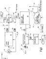
- the picking system 10 can have a goods receipt (WE) 12 , a warehouse 14 , a picking station 16 , a buffer and sorting area 18 , a packing station 20 and a dispatch or goods issue (WA) 22 .
- WE goods receipt
- WA dispatch or goods issue
- the system 10 has a control device 24 which communicates with the various elements of the system 10 via (fixed or wireless) data connections 26 .
- the elements 12 to 22 can be connected to one another in terms of material flow by means of one or more conveyor systems 32 (roller conveyors, belt conveyors, belt conveyors, chain conveyors, overhead conveyors, etc.).
- the one in the 1 The conveying connections shown are only of an exemplary nature. It is understood that further and different connections between the various elements 12 to 22 can be provided.
- the piece goods can be separated and/or repackaged in the incoming goods department 12 .
- piece goods that are delivered on pallets can be reloaded into containers or onto trays, which are then stored in the warehouse 14 as inventory units (SKUs).
- the warehouse 14 can be, for example, an automated small parts warehouse (AKL). It goes without saying that the warehouse 14 can also be realized by other types of warehouse, such as a high-bay warehouse, where, for example, piece goods are stored on (Euro) pallets as inventory units.
- the control device 24 has several tasks and can have a decentralized structure.
- the control device 24 can have a modular structure and implement the following functions: order management, picking control strategies, merchandise management system, which in turn can include warehouse management, which in turn can contain a material flow and space management, and/or interface management. These functions are typically implemented in software and/or hardware. Communication can take place via one (or more) communication bus(s).
- the control device 24 can be part of a central computer (not shown).
- Order management ensures that incoming (picking) orders 30 from customers 28 are distributed to one or more picking stations 16 for completion (processing), one of which, for example, is in the 1 is shown. Factors such as capacity utilization, general cargo range distribution, (conveyor) route optimization and the like play a role here. Complete orders, but also only partial orders, can be assigned to the picking station 16 for processing. However, "batch picking" is operated at the picking station(s) 16 . This means that all items are one specific article type (in parallel) for several orders 30 are picked. However, not all article types (order lines) of a picking order 30 have to be picked at the same picking station 16 .
- the picking station 16 serves as an order-picking workstation or refilling workstation, where the piece goods are picked up from a source (storage loading aids) and delivered to a destination (load carrier), as will be explained in more detail below.
- a picking order is usually not completely processed at the picking station 16 .
- the piece goods are reloaded into a buffer load carrier before they are later delivered to an order load carrier, as will be described in more detail below.
- the control device 24 is adapted to analyze incoming picking orders 30 to the effect that a large number of batches are formed, with a batch being characterized by the sum of all articles of a respective article type across all orders 30 .
- the control device 24 then generates corresponding transport commands for loading aids (LHM) 34, which are also referred to below as storage loading aids (LLHM) 34, and for load carriers (LT) 36.
- LHM 34 represent sources, while the LT 36 represent destinations.
- the LHM 34 can be pallets, containers, cartons, trays or the like, which are preferably kept available in the warehouse 14 as SKUs of a single type or article.
- the LT 36 can be implemented in the form of (hanging) bags 44 or the like.
- the LHM 34 are removed from shelves in the warehouse 14 (not shown) by means of storage and retrieval devices (not shown) and transported to the picking station 16 via a warehouse loading aid conveyor system 46 .
- the warehouse loading aid conveyor system 46 can be implemented by roller conveyors, belt conveyors, chain conveyors, belt conveyors or the like. In the following, the transport of storage containers will be considered as an example.
- the LT 36 are transported from and to the picking station 16 via a load carrier conveyor system 40 . (Hanging) bags 44, which are transported by means of an overhead conveyor or overhead conveyor system 42 (load carrier conveyor technology 40), will be considered as LT 36 in the following.
- An exemplary (transport) bag 44 for the overhead conveyor 42 is in the German patent application DE 10 2011 101 987 described, which was submitted on 05/17/2011.
- the pockets 44 are coupled to a traction device of the overhead conveyor 42 by means of adapters.
- An exemplary (sliding) adapter of the type mentioned above is in the German patent application DE 10 2011 045 725 shown, which was submitted on 09/08/2010.
- An exemplary pulling means in the form of a pull rod is in the German patent application DE 10 2011 053 426 filed on 11/30/2010.
- a sensor 38 (for example a light barrier, light sensor or the like) can be provided upstream of the picking station 16 in order to monitor and detect the supply of LHM 34 via the conveyor system 46.
- the (sometimes only partially) emptied LHM 34 can be transported via the conveyor system 46 to the warehouse 14 or the Goods are transported back 12 for the purpose of refilling.
- the removal of such an LHM 34 can in turn be monitored and recorded with a sensor 38 which is arranged downstream of the picking station 16 .
- the sensors 38 are in data communication with the controller 24 to enable the controller 24 to sense and coordinate LHM and LT currents with one another.
- the control device 24 ensures that when one or more LHM 34, which are specified by a current batch, is made available at the picking station 16 for removal, a corresponding number of empty LT 36, specified by the batch, is at the pick -Station 16 is deployed.
- the picking station 16 only a single article is ever removed from the LHM 34 to be processed and placed in an empty LT 36 .
- the LT 36 is then filled (i.e. one article per pocket 44) and can leave the picking station 16 via the conveyor system 40.
- One or more sensors 38 can be provided in the area of the conveyor system 40 on the input side and/or output side of the picking station 16 in order to monitor and record the inflow and/or outflow of empty or filled LT 36 .
- the sensors 38 if present, are connected to the control device 24 in terms of data technology.
- Filled LT 36 in particular bags 44 filled with only a single article, are transported to a buffer and sorting area 18 by the conveyor system 40.
- An exemplary implementation of the buffering and sorting area 18 is in the German patent application DE 10 2011 103 194 described, which was submitted on 05/31/2011.
- Another exemplary implementation of a sorter is in the German patent application DE 102011 104511 described, which was submitted on 06/15/2011.
- the piece goods were handled in an article-oriented manner.
- the piece goods are handled in an order-oriented manner.
- the ejection takes place in turn via the conveyor system 40, in a sorted order 30 according to order. It can be discharged to the packing station 20 and/or for dispatch or goods issue 22 .
- the articles can be removed from the LT 36 and reloaded into any loading aid 34 (pallet, container, carton, tray, etc.). will.
- the LT 36 emptied in this way can be transported back to the picking station 16 via the conveyor system 40 in order to be ready for new batches.
- the corresponding LHM 34 can be transported via a conveyor system 32 to the dispatch area 22, where the LHM 34 can be wrapped with a film, for example, to prevent the individual from slipping To prevent general cargo on the LHM 34.
- the LHM 34 that have been commissioned in this way are then sent to the customer 28 .
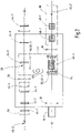
- FIG. 2 1 is a block diagram of an exemplary picking station 16, such as that shown in FIG 1 is used.
- the picking station 16 represents a (spatial) area within the picking system 10 where a picker 50 removes items manually from storage loading aids 34 and places them in load carriers 36 .
- the picking station 16 includes structural components necessary to accomplish this task.
- the picking station 16 has a work area 52 within which the manual work of the picker 50 takes place.
- the working area 52 is usually smaller than the (spatial/logical) area of the picking station 16.
- the picking station 16 is traversed both by the load carrier conveyor system 40 and by the warehouse loading aid conveyor system 46 .
- the load carrier conveyor system 40 is shown as an overhead conveyor 42 with pockets 44 as load carriers 36 .
- the storage loading aids conveyor system 46 is implemented as an example in the form of a roller conveyor 47 in order to transport, for example, (storage) containers 48 as storage loading aids 34 from and to the picking station 16 .
- Empty pockets 44 are in the 2 shown light, whereas filled pockets 44 are shown dark.
- Pockets 4.4-1 to 44-5 are empty.
- the pockets 44-6 and 44-7 are filled.
- the storage containers 48-1 to 48-3 are full.
- the storage bin 48-4 which is downstream of the picking station 16, is partially empty or completely empty.
- the work area 52 has a removal position 54 and a delivery position 58 .
- the removal position 54 represents the location of the provision of a (single) storage container 48.
- the storage container 48-3 is provided for the purpose of removing articles.
- a light grid 56 may be positioned above the opening of the bin 48 to monitor and detect the removal of articles from the bin 48-3.
- the storage container 48-3 serves as a source for a batch that is currently being processed.
- the storage container 48-3 preferably contains articles of a single article type and is thus unmixed. It goes without saying that storage containers 48 that are subdivided several times can also be used, in which case each compartment can then be filled with different types of articles.
- the removal position 54 is located in an area of the conveyor system 46 where the container 48-3 is stopped.
- the delivery position 58 is part of the conveyor system 40 and is preferably dimensioned such that only a single pocket 44, here the empty pocket 44-5, can be provided for the purpose of filling with a removed article.
- the delivery of an article removed from the storage container 48-3 into the empty pocket 44-5 is monitored and recorded, for example, with a light barrier 60, which is preferably arranged in the immediate area of the opening of the pocket 44-5.
- the light grid 56 at the removal position 54 and the light barrier 60 at the delivery position 58 represent a first monitoring device 62 - 1 and a second monitoring device 62 - 2 , which are connected to the control device 24 in terms of data technology.
- the controller 24 can thus track when an article is removed from the storage container 48-3 and when it is released into the pocket 44-5. Knowing this information, it is possible for the control device 24 to match or coordinate the load carrier flows and the storage loading aid flows in such a way that a filled bag 44 is automatically replaced by an empty bag 44 as soon as the delivery has taken place, without the order picker having to must confirm delivery manually. The same applies to the supply and removal of the containers 48.
- the control device 24 can cause the filled bag 44 to be transported away, such as the bags 44-6 and 44-7 being transported away. At the same time, the control device 24 can initiate the delivery of further empty pockets 44, such as the delivery of pockets 44-1 to 44-4.
- the empty pockets 44 - 1 to 44 - 4 are located in a (logical) charge carrier buffer 66 which represents a portion of the charge carrier conveyor system 40 which lies upstream of the delivery position 58 and is directly adjacent to the delivery position 58 .
- the buffer 66 can extend spatially beyond the picking station 16 .
- One goal of coordinating the various flows is to never keep the order picker 50 waiting.
- the picker 50 is therefore always provided with a storage container 48 and sufficient empty pockets 44 for processing the current batch.
- the control device 24 ensures that there are always enough empty pockets 44 in the buffer 66 . Analogously, the control device 24 ensures that there are always sufficient storage containers 48 in a storage loading aid buffer 68 in order to initiate a storage container exchange when all the articles in a storage container 48 have been removed and handed over. In this case, a current batch has been processed. A new "batch" then moves up in the form of a new storage container, which is implemented here as an example by the storage container 48-2. Acknowledgment buttons and the like are not required.
- FIG. 3 an exemplary embodiment of a picking station 16 is shown in a perspective view.
- the storage loading aids 34 are in turn implemented by way of example in the form of storage containers 48, which have the storage loading aids conveyor technology 46 in the Work area 52 are transported to the removal position 54.
- the conveyor system 46 can be covered with a housing 76 that has an opening 78 , for example.
- the opening 78 only allows access to a single storage container 48 .
- Four articles 84 (of one type) are shown in the storage container 48 as an example.
- the first monitoring device 62 - 1 in the form of a light grid 56 is shown above the opening of the storage container 48 , ie in the region of the opening 78 of the housing 76 .
- the light beams of the light grid 56 are indicated by several parallel double arrows.
- the storage containers 48 are fed in parallel to the longitudinal direction X (cf. arrow 72) and removed parallel to the transverse direction Z (cf. arrow 74).
- the conveyor system 46 is shown as an example in the form of a roller conveyor 47 .
- the dispensing position 58 is directly opposite the removal position 54 .
- the removal position 54 and the delivery position 58 can also be arranged at a distance from one another, care being taken to ensure that the order picker 50 has to walk as little as possible, and ideally not at all, to place a removed article 84 in an empty pocket 44 (Here the pocket 44-5 at the delivery position 58) to be delivered.
- the empty pockets 44 are transported to the delivery position 58 with the aid of an overhead conveyor 42 (cf. arrow 71).
- the load carrier conveyor system 40 ie the overhead conveyor 42, includes a guide rail 70, as disclosed in the German patent application cited above.
- the removal position 58 can be arranged slightly higher (Y-direction) than the removal position 54 in order to allow the conveyor systems 40 and 46 to cross. That is why the Pick-Station 16 is building 3 very compact.
- the second monitoring device 62 - 2 is also implemented in the form of a light grid 56 .
- the light beams of the second monitoring device 62-2 are also indicated in the form of parallel double arrows, which preferably extend in the XY plane immediately in front of the opening of the pocket 44-5.
- the second monitoring device 62-2 is designed in such a way that the delivery of a removed article 84 into the empty pocket 44-5 can be detected in any case.
- the delivery of the removed item 84 starts the tracking of a new empty pocket, here the pocket 44-4 and the removal of the pocket 44-5.
- the same applies to the first monitoring device 62-1 which is designed in such a way that the removal of an article 84 can be reliably detected.
- the controller 24 can thus keep track of how many articles 84 have been removed from the container 48 in order to determine the end of processing of the current batch. It is of great advantage if only a single article 84 can be removed and handed over. The picking performance at such a workplace can easily exceed 2000 picks per hour.
- the picking station 16 additionally has a display 80 and/or an input device 82 which are connected to the control device 24 in terms of information technology.
- a display 80 and/or an input device 82 which are connected to the control device 24 in terms of information technology.
- an image of the article 84 to be processed can be shown to the order picker 50 via the display 80 (e.g. monitor).
- the order picker 50 can report problems to the control device 24 via the input device 82 (e.g. keyboard).
- a storage bin 48 may not have the expected number of items 84 to deliver all of the items 84 in a batch to empty pockets 44 .
- the order picker 50 can inform the control device 24 about the "undersupply" so that the control device 24 can initiate suitable countermeasures.
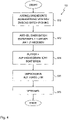
- a first flowchart 100 is shown, which shows the basic steps of the picking method used.
- the method 100 can be used both as a B2B and B2C solution, particularly in the area of e-commerce.
- a first step S10 an article-oriented outsourcing of SKUs takes place for the purpose of batch picking, after a group of orders 30 has been collected and analyzed and combined for the purpose of batch picking.
- all articles 84 are removed from a batch (one after the other), with only one article being removed at a time and placed in a pocket 44 (cf. step S12).
- the SKU is exchanged at the picking station 16 and a new group of empty load carriers 16 is provided in order to process the next batch or the new SKU.
- the filled load carriers 36 of the batch currently being processed are transported to the buffer and sorting area 18, where they can be sorted in an order-oriented manner (cf.
- step S14 The corresponding load carriers 36 then leave the area 18 in a sequence sorted according to orders, so that the filled load carriers 36 can then be repacked into an order loading aid in a step S16, to the extent that this is necessary.
- step S18 the order loading aids, which then contain all the articles of the order 30, can be shipped.
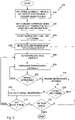
- FIG 5 a further flowchart 200 is shown, which describes the picking method according to the invention in more detail.
- a plurality of orders 30 are collected and analyzed in an article-oriented manner by the control device 24 for the purpose of batch picking. Corresponding batches are then formed in a step S22, in particular a sum of all articles of a respective article type forming a batch is summarized, so that all article types that occur in the group of picking orders 30 are processed in a respective batch.
- the control device 24 then generates corresponding transport commands for the storage loading aids 34 and the load carriers 36, which they transmit to the corresponding conveyor technology components.
- the control device 24 coordinates the flows of the storage loading aids 34 and the load carriers 36 in order to ensure that the order picker 50 can work continuously at the picking station 16, preferably without downtime or waiting time and manual acknowledgment.
- one or more storage loading aids 34 are provided for processing the current batch at the removal position 54 (cf. step S26). Accordingly, an empty load carrier 36 is provided at the removal position 58 (cf. step S28).
- a step S30 the removal of an article 84 from a storage loading aid 34 is monitored and recorded by the control device 24 being informed accordingly (cf. step S30).
- a step S32 it is queried whether an article 84 has been removed from the storage loading aid 34 provided at the removal position 54 . If no article 84 has been picked up, one returns to step S30. If an article 84 has been removed, the delivery of the removed article 84 is monitored and recorded in a step S34.
- the second monitoring device 62-2 is used for this purpose.
- a step S36 it is then queried whether the removed item 84 was actually delivered. If no delivery has been made, return to step S34. However, if the article 84 has been handed in, the full load carrier 36 is transported away in a step S38 (e.g. to the buffer and sorting area 18 of the 1 ). After that, a step S40 can be queried as to whether the current batch has now been completely processed, for example by checking the number of recorded article withdrawals (S30 and S32). If the current batch has not yet been completely processed, one returns to step S28. Otherwise, a query can be made in step S40 as to whether another batch is to be processed. If another batch is to be processed, one returns to step S26. Otherwise the method of the invention ends.
- the selection of the orientation of the coordinate systems was generally based on the designation customary in warehouse logistics, so that the longitudinal direction was denoted by X, the transverse direction by Z and the (vertical) height by Y.
Landscapes
- Engineering & Computer Science (AREA)
- Mechanical Engineering (AREA)
Claims (13)
- Système de préparation de commandes (10), qui fonctionne selon le principe "marchandises vers l'homme", avec:un stock d'articles (12);un mécanisme de transport de contenants de stockage (46) pour le transport automatisé de contenants de stockage (34) à partir du et vers le stock d'articles (12);un mécanisme de transport de contenants de charge (40) pour le transport de contenants de charge (36), dans lequel chaque contenant de charge (36) est configuré pour contenir un article (84), afin de transporter l'article (84) à l'intérieur du système de préparation de commandes (10);une station de manutention (16), qui est pilotée par un préparateur de commandes (50) et qui est reliée selon la technique du flux de matières au stock d'articles (12) au moyen du mécanisme de transport de contenants de stockage (46) et qui est couplée selon la technique du flux de matières au mécanisme de transport de contenants de charge (40), dans lequel la station de manutention (16) présente un premier dispositif de surveillance (62-1) et un deuxième dispositif de surveillance (62-2), dans lequel le premier dispositif de surveillance (62-1) est disposé de telle manière qu'un prélèvement manuel d'un article (84) hors d'un des contenants de stockage (34) préparés à une position de prélèvement (54) puisse être détecté, et dans lequel le deuxième dispositif de surveillance (62-2) est disposé de telle manière qu'une délivrance manuelle de l'article prélevé (84) dans exactement un des contenants de charge (36; 44-5) préparés à une position de délivrance (58) puisse être détectée, dans lequel la position de prélèvement (54) et la position de délivrance (58) sont disposées à l'intérieur d'une zone de travail (52) de la station de manutention (16), où le préparateur de commandes (50) prélève et délivre des articles (84); etun dispositif de commande (24), qui est relié selon la technique de communication au premier dispositif de surveillance (62-1) et au deuxième dispositif de surveillance (62-2), caractérisé en ce queune multiplicité d'articles différents (84) sont stockés dans le stock d'articles (12) triés par sortes dans les contenants de stockage (34);le dispositif de commande (24) est apte à traiter une multiplicité de commandes de clients (30) en orientation par articles, de telle manière que les contenants de stockage (34) soient transportés depuis le stock d'articles (12) pour la manutention par lots jusqu'à la station de manutention (16), etle dispositif de commande (24) est apte à assurer le suivi d'un nombre de prélèvements d'articles hors du contenant de stockage (34) préparé à la position de prélèvement (54), afin d'opérer un échange de contenant de stockage à la position de prélèvement (54), lorsqu'un nombre d'articles (84) prédéterminé par la manutention par lots ont été prélevés hors du contenant de stockage (34) préparé à la position de prélèvement (54), et afin d'opérer respectivement un échange de contenant de charge à la position de délivrance (58), lorsque la délivrance de l'article prélevé (84) dans le contenant de charge préparé (36; 44-5) a été détectée.
- Système de préparation de commandes selon la revendication 1, dans lequel le mécanisme de transport de contenants de charge (40) est un système de transport suspendu (42) et dans lequel les contenants de charge (36) sont des poches (44), qui sont transportées de préférence par des adaptateurs de transport du système de transport suspendu (42).
- Système de préparation de commandes selon une des revendications 1 ou 2, dans lequel le mécanisme de transport de contenants de charge (40) présente une zone tampon (66), qui est située en amont de la position de délivrance (58) et est adjacente à celle-ci, et dans lequel le dispositif de commande (24) est apte à accorder l'un à l'autre un courant de contenants de stockage et un courant de contenants de charge, de telle manière qu'il y ait toujours en réserve dans la zone tampon (66) au moins autant de contenants de charge (36) qu'il y a d'articles (84) à prélever hors du contenant de stockage (34) préparé à la position de prélèvement (54).
- Système de préparation de commandes selon l'une quelconque des revendications 1 à 3, dans lequel le dispositif de commande (24) est apte à coordonner un courant de contenants de charge à la position de délivrance (58), de telle manière que pour chaque article (84) d'un lot un contenant de charge (36) soit chaque fois préparé sans temps d'attente pour le préparateur de commandes (50) dans la zone de travail (52).
- Système de préparation de commandes selon l'une quelconque des revendications 1 à 4, dans lequel uniquement un seul article (84) est toujours prélevé hors du contenant de stockage (34) préparé à la position de prélèvement (54) et délivré dans le contenant de charge (36) préparé à la position de délivrance (58).
- Système de préparation de commandes selon l'une quelconque des revendications 1 à 5, qui présente en outre une zone de tampon et de tri (18), une station d'emballage (20) et/ou une station d'expédition (22).
- Système de préparation de commandes selon l'une quelconque des revendications 1 à 6, dans lequel la station de manutention (16) présente au moins un autre dispositif de surveillance (62), qui est disposé immédiatement en amont avant la position de prélèvement (54), en aval après la position de prélèvement (54), amont avant la position de délivrance (58) et/ou en aval après la position de délivrance (58).
- Système de préparation de commandes selon l'une quelconque des revendications 1 à 7, dans lequel la position de prélèvement (54) est configurée de telle manière que le préparateur de commandes (50) ne puisse accéder manuellement qu'au contenant de stockage (34) préparé à la position de prélèvement (54).
- Système de préparation de commandes selon la revendication 8, dans lequel la station de manutention (16) présente une enceinte fermée (76), qui présente à la position de prélèvement (54) une ouverture (78), qui présente une grandeur telle que seul le contenant de stockage préparé (34) soit accessible, tandis que le préparateur de commandes (50) ne peut pas accéder pour prélever un article à des contenants de stockage (34), qui sont transportés dans la zone de travail (52) sur le mécanisme de transport de contenants de stockage (46).
- Système de préparation de commandes selon l'une quelconque des revendications 1 à 9, dans lequel la position de prélèvement (54) et la position de délivrance (58) sont disposées à proximité l'une de l'autre, de telle manière que le préparateur de commandes (50) ne doive pas marcher entre le prélèvement et la délivrance d'un article (84).
- Système de préparation de commandes selon l'une quelconque des revendications 1 à 10, dans lequel la position de prélèvement (54) se trouve, par rapport à une hauteur (Y), en dessous de la position de délivrance (58).
- Système de préparation de commandes selon l'une quelconque des revendications 1 à 11, dans lequel le dispositif de commande (24) est apte à opérer une fourniture cadencée des contenants de stockage (34) et des contenants de charge (36) à la station de manutention (16).
- Procédé pour la manutention manuelle par lots d'une multiplicité de commandes à préparer, dans lequel on manipule des articles à préparer (84) selon le principe "marchandises vers l'homme", dans lequel on utilise un système de préparation de commandes (10) selon l'une quelconque des revendications 1 à 12, comprenant les étapes suivantes:a) préparer un contenant de stockage (34) à une position de prélèvement (54) pour l'élaboration d'un lot actuel;b) préparer un contenant de charge vide (36) à une position de délivrance (58);
prélever un article hors du contenant de stockage préparé et délivrer un seul article prélevé dans le contenant de charge vide préparé;c) surveiller et détecter le prélèvement de l'article (84), de préférence unique, hors du contenant de stockage (34) préparé à la position de prélèvement (54);d) surveiller et détecter la délivrance de l'article unique prélevé (84) à la position de délivrance (58), lorsque le prélèvement de l'article (84) a été détecté;e) évacuer le contenant de charge rempli (36) préparé à la position de délivrance (58), lorsque la délivrance de l'article prélevé (84) a été détectée;f) demander si le lot actuel est complètement terminé, et retourner à l'étape b), lorsque le lot actuel n'est pas complètement terminé, et sinon;g) demander si un autre lot doit être élaboré; eth) retourner à l'étape a), lorsqu'un autre lot doit être élaboré.
Applications Claiming Priority (2)
| Application Number | Priority Date | Filing Date | Title |
|---|---|---|---|
| DE102011116081A DE102011116081B3 (de) | 2011-10-10 | 2011-10-10 | System und Verfahren zum manuellen Batch-Picken unter Anwendung des Ware-zum-Mann-Prinzips |
| PCT/EP2012/070044 WO2013053747A1 (fr) | 2011-10-10 | 2012-10-10 | Système et procédé de prélèvement manuel par lots selon le principe marchandises vers l'homme |
Publications (3)
| Publication Number | Publication Date |
|---|---|
| EP2766285A1 EP2766285A1 (fr) | 2014-08-20 |
| EP2766285B1 EP2766285B1 (fr) | 2017-04-12 |
| EP2766285B2 true EP2766285B2 (fr) | 2022-04-06 |
Family
ID=47022653
Family Applications (1)
| Application Number | Title | Priority Date | Filing Date |
|---|---|---|---|
| EP12772916.8A Active EP2766285B2 (fr) | 2011-10-10 | 2012-10-10 | Système et procédé de prélèvement manuel par lots selon le principe marchandises vers l'homme |
Country Status (3)
| Country | Link |
|---|---|
| EP (1) | EP2766285B2 (fr) |
| DE (1) | DE102011116081B3 (fr) |
| WO (1) | WO2013053747A1 (fr) |
Cited By (1)
| Publication number | Priority date | Publication date | Assignee | Title |
|---|---|---|---|---|
| DE102021132568A1 (de) | 2021-12-09 | 2023-06-15 | Dematic Gmbh | System und Verfahren zur Abarbeitung einer Vielzahl von Kommissionieraufträgen mit mehreren Artikeln |
Families Citing this family (22)
| Publication number | Priority date | Publication date | Assignee | Title |
|---|---|---|---|---|
| DE102011116081B3 (de) | 2011-10-10 | 2013-04-11 | SSI Schäfer PEEM GmbH | System und Verfahren zum manuellen Batch-Picken unter Anwendung des Ware-zum-Mann-Prinzips |
| EP2862818A1 (fr) * | 2013-10-18 | 2015-04-22 | Dematic Accounting Services GmbH | Procédé de réalisation de commande en rendant disponible les unités de stockage à partir d'une installation de stockage dans une séquence souhaitée au niveau d'une station de prélèvement |
| AT14694U1 (de) | 2015-08-19 | 2016-04-15 | Knapp Ag | Kommissionierplatz zum Kommissionieren von Artikeln in Auftragsbehälter und Fördertaschen zur Auftrags- und Batchkommissionierung |
| AT15289U1 (de) | 2016-06-14 | 2017-05-15 | Knapp Ag | Kommissioniersystem mit einem Transportroboter zum Unterfahren von Einzelregalen |
| US10329089B2 (en) | 2016-07-20 | 2019-06-25 | Dematic Corp. | Order fulfillment system and method with sortation at induct |
| CH713398A1 (de) | 2017-01-31 | 2018-07-31 | Ferag Ag | Vorrichtung zum Entleeren hängend geförderter Transporttaschen. |
| CH713399A1 (de) | 2017-01-31 | 2018-07-31 | Ferag Ag | Fördereinheit zum hängenden Transport von Transportelementen in zwei Positionen. |
| CN108357886A (zh) * | 2017-01-26 | 2018-08-03 | 菜鸟智能物流控股有限公司 | 物品拣选方法及相关设备 |
| US11878876B2 (en) | 2017-01-31 | 2024-01-23 | Ferag Ag | Device for emptying transport bags conveyed in a suspended manner |
| CH719878A1 (de) * | 2022-07-08 | 2024-01-15 | Ferag Ag | Vorrichtung, Verfahren und System zur Kommissionierung von Stückgütern. |
| CH713551A1 (de) | 2017-03-07 | 2018-09-14 | Ferag Ag | Verfahren zum Kommissionieren von Waren und Kommissionierungsanlage zur Durchführung des Verfahrens. |
| CN107555056B (zh) * | 2017-09-30 | 2024-02-27 | 兰剑智能科技股份有限公司 | 料箱存储拣选系统和储分一体化系统 |
| EP3575246B1 (fr) * | 2018-05-29 | 2022-12-07 | Schaefer Systems International Inc. | Système à base de groupes et procédé de mise en oeuvre d'une commande de commerce électronique |
| US10427873B1 (en) | 2018-05-29 | 2019-10-01 | Schaefer Systems International, Inc. | Cluster-based-system and method for E-commerce-order fulfillment |
| DE102018114177B4 (de) * | 2018-06-13 | 2022-08-11 | Ssi Schäfer Automation Gmbh | System und Verfahren zum Kommissionieren und Ausliefern von Artikeln eines Online-Supermarkts |
| AT17770U1 (de) | 2018-06-21 | 2023-02-15 | Tgw Logistics Group Gmbh | Lager- und Kommissioniersystem sowie Kommissionierverfahren mit verbessertem Warentransfer zwischen zwei Lagerbereichen |
| WO2019241816A1 (fr) | 2018-06-21 | 2019-12-26 | Tgw Logistics Group Gmbh | Système d'emmagasinage et de préparation de commandes et procédé de préparation de commandes d'articles commandés provenant d'un sac suspendu et d'un autre moyen de chargement |
| AT17767U1 (de) | 2018-06-21 | 2023-02-15 | Tgw Logistics Group Gmbh | Lager- und Kommissioniersystem sowie Kommissionierverfahren mit verbessertem Warentransfer zwischen zwei Lagerbereichen |
| CH715134A1 (de) | 2018-06-28 | 2019-12-30 | Ferag Ag | Vorrichtung und Verfahren zur Inspektion von hängend förderbaren Transporttaschen. |
| EP3826943B1 (fr) | 2018-07-23 | 2022-06-08 | TGW Logistics Group GmbH | Système d'entreposage et de préparation de commandes présentant un temps de cycle réduit et procédé de fonctionnement de celui-ci |
| DE102018219583B4 (de) | 2018-11-15 | 2020-08-13 | Dürkopp Fördertechnik GmbH | Förderanlage und Verfahren zum Fördern von Waren |
| EP4242142A1 (fr) * | 2022-03-08 | 2023-09-13 | Ferag Ag | Dispositif, procédé et système de préparation de commandes de marchandises de détail |
Family Cites Families (9)
| Publication number | Priority date | Publication date | Assignee | Title |
|---|---|---|---|---|
| DE10307949A1 (de) * | 2003-02-25 | 2004-09-09 | Witron Logistik + Informatik Gmbh | System und Verfahren zum Kommissionieren von in Lagerbehältern befindlichen Artikeln |
| DE102004001841A1 (de) * | 2004-01-07 | 2005-08-04 | SSI Schäfer PEEM GmbH | Kommissionierplatz |
| DE102004002831B4 (de) | 2004-01-13 | 2010-06-17 | SSI Schäfer PEEM GmbH | Kommissionierplatz und Verfahren zum Kommissionieren mit einem Lichtgitter |
| DE102007011856B4 (de) | 2007-03-05 | 2011-01-20 | SSI Schäfer Noell GmbH Lager- und Systemtechnik | Doppelseitig zugängliches Kommissionierregal und Kommissionierverfahren |
| DE102008057630A1 (de) * | 2008-11-10 | 2010-05-27 | Langen, Manfred | Kommissionieranlage und Verfahren zum Betreiben derselben mit einem Kommissionierwagen |
| JP5441393B2 (ja) | 2008-11-13 | 2014-03-12 | オークラ輸送機株式会社 | ピッキングシステム |
| DE102008061685A1 (de) | 2008-12-11 | 2010-06-17 | Dürkopp Adler AG | Belade-Station für in einer Hänge-Förder-Anlage transportierte Transport-Taschen |
| DE102011103194A1 (de) * | 2011-05-31 | 2012-12-06 | SSI Schäfer PEEM GmbH | Verteileinrichtung und Verfahren zum Zusammenstellen einer Gruppe von Fördergütern |
| DE102011116081B3 (de) | 2011-10-10 | 2013-04-11 | SSI Schäfer PEEM GmbH | System und Verfahren zum manuellen Batch-Picken unter Anwendung des Ware-zum-Mann-Prinzips |
-
2011
- 2011-10-10 DE DE102011116081A patent/DE102011116081B3/de not_active Expired - Fee Related
-
2012
- 2012-10-10 WO PCT/EP2012/070044 patent/WO2013053747A1/fr active Application Filing
- 2012-10-10 EP EP12772916.8A patent/EP2766285B2/fr active Active
Cited By (1)
| Publication number | Priority date | Publication date | Assignee | Title |
|---|---|---|---|---|
| DE102021132568A1 (de) | 2021-12-09 | 2023-06-15 | Dematic Gmbh | System und Verfahren zur Abarbeitung einer Vielzahl von Kommissionieraufträgen mit mehreren Artikeln |
Also Published As
| Publication number | Publication date |
|---|---|
| DE102011116081B3 (de) | 2013-04-11 |
| WO2013053747A1 (fr) | 2013-04-18 |
| EP2766285A1 (fr) | 2014-08-20 |
| EP2766285B1 (fr) | 2017-04-12 |
Similar Documents
| Publication | Publication Date | Title |
|---|---|---|
| EP2766285B2 (fr) | Système et procédé de prélèvement manuel par lots selon le principe marchandises vers l'homme | |
| EP3341308B1 (fr) | Système d'entreposage et de préparation de commandes | |
| DE102015118832B3 (de) | Lager- und Kommissioniersystem sowie Verfahren zum Einlagern von Stückgütern in einen Kommissionier-Automat | |
| DE102009019511B3 (de) | Lager-und Kommissioniersystem und Verfahren zum Betreiben desselben im Batch-Betrieb | |
| AT518818B1 (de) | Verfahren zum Kommissionieren von Artikeln und Kommissionierstation | |
| EP2173644B1 (fr) | Système et procédé pour manipuler des marchandises de retour dans une installation de préparation de commandes | |
| EP3826943B1 (fr) | Système d'entreposage et de préparation de commandes présentant un temps de cycle réduit et procédé de fonctionnement de celui-ci | |
| EP3330200A1 (fr) | Procédé de stockage et de distribution d'objets ainsi que système de stockage permettant la mise en uvre dudit procédé | |
| WO2016066578A1 (fr) | Procédé et système d'approvisionnement | |
| EP3807193A1 (fr) | Préparation de commandes en deux étapes au moyen de trieurs dotés de plateaux de sélection hautement dynamiques | |
| AT512338A1 (de) | Kommissionierstation und verfahren zum kommissionieren von artikeln | |
| EP0847939B2 (fr) | Dispositif et procédé pour rassembler et préparer des marchandises en détail | |
| EP1452462A2 (fr) | Système et procédé pour la préparation de commandes d'articles stockés dans des conteneurs | |
| AT503473A1 (de) | Automatisiertes system und verfahren zum automatischen kommissionieren oder konsolidieren von artikeln | |
| EP2154088B1 (fr) | Procédé et système pour la préparation de commandes à partir d'articles entreposés dans un magasin de palettes | |
| AT510745A1 (de) | Kommissionierverfahren und -system | |
| EP3810530B1 (fr) | Système d'emmagasinage et de préparation de commandes et procédé de préparation de commandes d'articles commandés provenant d'un sac suspendu et d'un autre moyen de chargement | |
| AT520973A1 (de) | Kommissionierstation und Verfahren zum automatischen Kommissionieren von Waren | |
| DE10200077B4 (de) | Kommissioniersystem mit Entkopplungspuffer | |
| DE102013108934A1 (de) | System und Verfahren zum gemeinsamen Kommissionieren von zerbrechlichen und unzerbrechlichen Artikeln | |
| EP3924274A1 (fr) | Système de stockage et de préparation de commandes présentant une performance d'emmagasinage améliorée et procédé pour le faire fonctionner | |
| EP3870527B1 (fr) | Système de stockage et de préparation de commandes et procédé de préparation automatique et manuelle de commandes d'objets | |
| EP3592669B1 (fr) | Procédé pour extraire des marchandises se trouvant dans un stock pour exécuter une commande | |
| EP2301864B1 (fr) | Procédé destiné au fonctionnement d'un dispositif de commissionnement et dispositif de commissionnement | |
| WO2023095049A1 (fr) | Dispositif de gestion du chargement d'unités de transport d'un système d'acheminement |
Legal Events
| Date | Code | Title | Description |
|---|---|---|---|
| PUAI | Public reference made under article 153(3) epc to a published international application that has entered the european phase |
Free format text: ORIGINAL CODE: 0009012 |
|
| 17P | Request for examination filed |
Effective date: 20140318 |
|
| AK | Designated contracting states |
Kind code of ref document: A1 Designated state(s): AL AT BE BG CH CY CZ DE DK EE ES FI FR GB GR HR HU IE IS IT LI LT LU LV MC MK MT NL NO PL PT RO RS SE SI SK SM TR |
|
| DAX | Request for extension of the european patent (deleted) | ||
| 17Q | First examination report despatched |
Effective date: 20160204 |
|
| GRAP | Despatch of communication of intention to grant a patent |
Free format text: ORIGINAL CODE: EPIDOSNIGR1 |
|
| STAA | Information on the status of an ep patent application or granted ep patent |
Free format text: STATUS: GRANT OF PATENT IS INTENDED |
|
| INTG | Intention to grant announced |
Effective date: 20161213 |
|
| GRAS | Grant fee paid |
Free format text: ORIGINAL CODE: EPIDOSNIGR3 |
|
| GRAA | (expected) grant |
Free format text: ORIGINAL CODE: 0009210 |
|
| STAA | Information on the status of an ep patent application or granted ep patent |
Free format text: STATUS: THE PATENT HAS BEEN GRANTED |
|
| AK | Designated contracting states |
Kind code of ref document: B1 Designated state(s): AL AT BE BG CH CY CZ DE DK EE ES FI FR GB GR HR HU IE IS IT LI LT LU LV MC MK MT NL NO PL PT RO RS SE SI SK SM TR |
|
| REG | Reference to a national code |
Ref country code: GB Ref legal event code: FG4D Free format text: NOT ENGLISH |
|
| REG | Reference to a national code |
Ref country code: CH Ref legal event code: EP |
|
| REG | Reference to a national code |
Ref country code: DE Ref legal event code: R081 Ref document number: 502012010060 Country of ref document: DE Owner name: SSI SCHAEFER AUTOMATION GMBH, AT Free format text: FORMER OWNER: SSI SCHAEFER PEEM GMBH, GRAZ, AT Ref country code: DE Ref legal event code: R082 Ref document number: 502012010060 Country of ref document: DE Representative=s name: WITTE, WELLER & PARTNER PATENTANWAELTE MBB, DE |
|
| REG | Reference to a national code |
Ref country code: IE Ref legal event code: FG4D Free format text: LANGUAGE OF EP DOCUMENT: GERMAN |
|
| REG | Reference to a national code |
Ref country code: AT Ref legal event code: REF Ref document number: 883628 Country of ref document: AT Kind code of ref document: T Effective date: 20170515 |
|
| REG | Reference to a national code |
Ref country code: DE Ref legal event code: R096 Ref document number: 502012010060 Country of ref document: DE |
|
| RAP2 | Party data changed (patent owner data changed or rights of a patent transferred) |
Owner name: SSI SCHAEFER AUTOMATION GMBH |
|
| RAP2 | Party data changed (patent owner data changed or rights of a patent transferred) |
Owner name: SSI SCHAEFER AUTOMATION GMBH |
|
| REG | Reference to a national code |
Ref country code: NL Ref legal event code: FP |
|
| REG | Reference to a national code |
Ref country code: AT Ref legal event code: HC Ref document number: 883628 Country of ref document: AT Kind code of ref document: T Owner name: SSI SCHAEFER AUTOMATION GMBH, AT Effective date: 20170629 |
|
| REG | Reference to a national code |
Ref country code: LT Ref legal event code: MG4D |
|
| REG | Reference to a national code |
Ref country code: FR Ref legal event code: PLFP Year of fee payment: 6 |
|
| PG25 | Lapsed in a contracting state [announced via postgrant information from national office to epo] |
Ref country code: FI Free format text: LAPSE BECAUSE OF FAILURE TO SUBMIT A TRANSLATION OF THE DESCRIPTION OR TO PAY THE FEE WITHIN THE PRESCRIBED TIME-LIMIT Effective date: 20170412 Ref country code: LT Free format text: LAPSE BECAUSE OF FAILURE TO SUBMIT A TRANSLATION OF THE DESCRIPTION OR TO PAY THE FEE WITHIN THE PRESCRIBED TIME-LIMIT Effective date: 20170412 Ref country code: GR Free format text: LAPSE BECAUSE OF FAILURE TO SUBMIT A TRANSLATION OF THE DESCRIPTION OR TO PAY THE FEE WITHIN THE PRESCRIBED TIME-LIMIT Effective date: 20170713 Ref country code: HR Free format text: LAPSE BECAUSE OF FAILURE TO SUBMIT A TRANSLATION OF THE DESCRIPTION OR TO PAY THE FEE WITHIN THE PRESCRIBED TIME-LIMIT Effective date: 20170412 Ref country code: NO Free format text: LAPSE BECAUSE OF FAILURE TO SUBMIT A TRANSLATION OF THE DESCRIPTION OR TO PAY THE FEE WITHIN THE PRESCRIBED TIME-LIMIT Effective date: 20170712 Ref country code: ES Free format text: LAPSE BECAUSE OF FAILURE TO SUBMIT A TRANSLATION OF THE DESCRIPTION OR TO PAY THE FEE WITHIN THE PRESCRIBED TIME-LIMIT Effective date: 20170412 |
|
| PG25 | Lapsed in a contracting state [announced via postgrant information from national office to epo] |
Ref country code: IS Free format text: LAPSE BECAUSE OF FAILURE TO SUBMIT A TRANSLATION OF THE DESCRIPTION OR TO PAY THE FEE WITHIN THE PRESCRIBED TIME-LIMIT Effective date: 20170812 Ref country code: LV Free format text: LAPSE BECAUSE OF FAILURE TO SUBMIT A TRANSLATION OF THE DESCRIPTION OR TO PAY THE FEE WITHIN THE PRESCRIBED TIME-LIMIT Effective date: 20170412 Ref country code: PL Free format text: LAPSE BECAUSE OF FAILURE TO SUBMIT A TRANSLATION OF THE DESCRIPTION OR TO PAY THE FEE WITHIN THE PRESCRIBED TIME-LIMIT Effective date: 20170412 Ref country code: BG Free format text: LAPSE BECAUSE OF FAILURE TO SUBMIT A TRANSLATION OF THE DESCRIPTION OR TO PAY THE FEE WITHIN THE PRESCRIBED TIME-LIMIT Effective date: 20170712 Ref country code: SE Free format text: LAPSE BECAUSE OF FAILURE TO SUBMIT A TRANSLATION OF THE DESCRIPTION OR TO PAY THE FEE WITHIN THE PRESCRIBED TIME-LIMIT Effective date: 20170412 Ref country code: RS Free format text: LAPSE BECAUSE OF FAILURE TO SUBMIT A TRANSLATION OF THE DESCRIPTION OR TO PAY THE FEE WITHIN THE PRESCRIBED TIME-LIMIT Effective date: 20170412 |
|
| REG | Reference to a national code |
Ref country code: DE Ref legal event code: R026 Ref document number: 502012010060 Country of ref document: DE |
|
| PLBI | Opposition filed |
Free format text: ORIGINAL CODE: 0009260 |
|
| PG25 | Lapsed in a contracting state [announced via postgrant information from national office to epo] |
Ref country code: EE Free format text: LAPSE BECAUSE OF FAILURE TO SUBMIT A TRANSLATION OF THE DESCRIPTION OR TO PAY THE FEE WITHIN THE PRESCRIBED TIME-LIMIT Effective date: 20170412 Ref country code: RO Free format text: LAPSE BECAUSE OF FAILURE TO SUBMIT A TRANSLATION OF THE DESCRIPTION OR TO PAY THE FEE WITHIN THE PRESCRIBED TIME-LIMIT Effective date: 20170412 Ref country code: CZ Free format text: LAPSE BECAUSE OF FAILURE TO SUBMIT A TRANSLATION OF THE DESCRIPTION OR TO PAY THE FEE WITHIN THE PRESCRIBED TIME-LIMIT Effective date: 20170412 Ref country code: DK Free format text: LAPSE BECAUSE OF FAILURE TO SUBMIT A TRANSLATION OF THE DESCRIPTION OR TO PAY THE FEE WITHIN THE PRESCRIBED TIME-LIMIT Effective date: 20170412 Ref country code: SK Free format text: LAPSE BECAUSE OF FAILURE TO SUBMIT A TRANSLATION OF THE DESCRIPTION OR TO PAY THE FEE WITHIN THE PRESCRIBED TIME-LIMIT Effective date: 20170412 |
|
| PLAX | Notice of opposition and request to file observation + time limit sent |
Free format text: ORIGINAL CODE: EPIDOSNOBS2 |
|
| 26 | Opposition filed |
Opponent name: DUERKOPP FOERDERTECHNIK GMBH Effective date: 20180112 |
|
| PG25 | Lapsed in a contracting state [announced via postgrant information from national office to epo] |
Ref country code: IT Free format text: LAPSE BECAUSE OF FAILURE TO SUBMIT A TRANSLATION OF THE DESCRIPTION OR TO PAY THE FEE WITHIN THE PRESCRIBED TIME-LIMIT Effective date: 20170412 Ref country code: SM Free format text: LAPSE BECAUSE OF FAILURE TO SUBMIT A TRANSLATION OF THE DESCRIPTION OR TO PAY THE FEE WITHIN THE PRESCRIBED TIME-LIMIT Effective date: 20170412 |
|
| PG25 | Lapsed in a contracting state [announced via postgrant information from national office to epo] |
Ref country code: MC Free format text: LAPSE BECAUSE OF FAILURE TO SUBMIT A TRANSLATION OF THE DESCRIPTION OR TO PAY THE FEE WITHIN THE PRESCRIBED TIME-LIMIT Effective date: 20170412 Ref country code: SI Free format text: LAPSE BECAUSE OF FAILURE TO SUBMIT A TRANSLATION OF THE DESCRIPTION OR TO PAY THE FEE WITHIN THE PRESCRIBED TIME-LIMIT Effective date: 20170412 |
|
| REG | Reference to a national code |
Ref country code: CH Ref legal event code: PL |
|
| PLBB | Reply of patent proprietor to notice(s) of opposition received |
Free format text: ORIGINAL CODE: EPIDOSNOBS3 |
|
| GBPC | Gb: european patent ceased through non-payment of renewal fee |
Effective date: 20171010 |
|
| REG | Reference to a national code |
Ref country code: IE Ref legal event code: MM4A |
|
| PG25 | Lapsed in a contracting state [announced via postgrant information from national office to epo] |
Ref country code: LU Free format text: LAPSE BECAUSE OF NON-PAYMENT OF DUE FEES Effective date: 20171010 Ref country code: CH Free format text: LAPSE BECAUSE OF NON-PAYMENT OF DUE FEES Effective date: 20171031 Ref country code: GB Free format text: LAPSE BECAUSE OF NON-PAYMENT OF DUE FEES Effective date: 20171010 Ref country code: LI Free format text: LAPSE BECAUSE OF NON-PAYMENT OF DUE FEES Effective date: 20171031 |
|
| REG | Reference to a national code |
Ref country code: BE Ref legal event code: MM Effective date: 20171031 |
|
| PG25 | Lapsed in a contracting state [announced via postgrant information from national office to epo] |
Ref country code: BE Free format text: LAPSE BECAUSE OF NON-PAYMENT OF DUE FEES Effective date: 20171031 |
|
| PG25 | Lapsed in a contracting state [announced via postgrant information from national office to epo] |
Ref country code: MT Free format text: LAPSE BECAUSE OF FAILURE TO SUBMIT A TRANSLATION OF THE DESCRIPTION OR TO PAY THE FEE WITHIN THE PRESCRIBED TIME-LIMIT Effective date: 20170412 |
|
| REG | Reference to a national code |
Ref country code: FR Ref legal event code: PLFP Year of fee payment: 7 |
|
| PG25 | Lapsed in a contracting state [announced via postgrant information from national office to epo] |
Ref country code: IE Free format text: LAPSE BECAUSE OF NON-PAYMENT OF DUE FEES Effective date: 20171010 |
|
| PG25 | Lapsed in a contracting state [announced via postgrant information from national office to epo] |
Ref country code: HU Free format text: LAPSE BECAUSE OF FAILURE TO SUBMIT A TRANSLATION OF THE DESCRIPTION OR TO PAY THE FEE WITHIN THE PRESCRIBED TIME-LIMIT; INVALID AB INITIO Effective date: 20121010 |
|
| PG25 | Lapsed in a contracting state [announced via postgrant information from national office to epo] |
Ref country code: CY Free format text: LAPSE BECAUSE OF NON-PAYMENT OF DUE FEES Effective date: 20170412 |
|
| PG25 | Lapsed in a contracting state [announced via postgrant information from national office to epo] |
Ref country code: MK Free format text: LAPSE BECAUSE OF FAILURE TO SUBMIT A TRANSLATION OF THE DESCRIPTION OR TO PAY THE FEE WITHIN THE PRESCRIBED TIME-LIMIT Effective date: 20170412 |
|
| PG25 | Lapsed in a contracting state [announced via postgrant information from national office to epo] |
Ref country code: TR Free format text: LAPSE BECAUSE OF FAILURE TO SUBMIT A TRANSLATION OF THE DESCRIPTION OR TO PAY THE FEE WITHIN THE PRESCRIBED TIME-LIMIT Effective date: 20170412 |
|
| PG25 | Lapsed in a contracting state [announced via postgrant information from national office to epo] |
Ref country code: PT Free format text: LAPSE BECAUSE OF FAILURE TO SUBMIT A TRANSLATION OF THE DESCRIPTION OR TO PAY THE FEE WITHIN THE PRESCRIBED TIME-LIMIT Effective date: 20170412 |
|
| PG25 | Lapsed in a contracting state [announced via postgrant information from national office to epo] |
Ref country code: AL Free format text: LAPSE BECAUSE OF FAILURE TO SUBMIT A TRANSLATION OF THE DESCRIPTION OR TO PAY THE FEE WITHIN THE PRESCRIBED TIME-LIMIT Effective date: 20170412 |
|
| PUAH | Patent maintained in amended form |
Free format text: ORIGINAL CODE: 0009272 |
|
| STAA | Information on the status of an ep patent application or granted ep patent |
Free format text: STATUS: PATENT MAINTAINED AS AMENDED |
|
| 27A | Patent maintained in amended form |
Effective date: 20220406 |
|
| AK | Designated contracting states |
Kind code of ref document: B2 Designated state(s): AL AT BE BG CH CY CZ DE DK EE ES FI FR GB GR HR HU IE IS IT LI LT LU LV MC MK MT NL NO PL PT RO RS SE SI SK SM TR |
|
| REG | Reference to a national code |
Ref country code: DE Ref legal event code: R102 Ref document number: 502012010060 Country of ref document: DE |
|
| REG | Reference to a national code |
Ref country code: NL Ref legal event code: FP |
|
| P01 | Opt-out of the competence of the unified patent court (upc) registered |
Effective date: 20240117 |
|
| PGFP | Annual fee paid to national office [announced via postgrant information from national office to epo] |
Ref country code: NL Payment date: 20241021 Year of fee payment: 13 |
|
| PGFP | Annual fee paid to national office [announced via postgrant information from national office to epo] |
Ref country code: DE Payment date: 20241121 Year of fee payment: 13 |
|
| PGFP | Annual fee paid to national office [announced via postgrant information from national office to epo] |
Ref country code: AT Payment date: 20241022 Year of fee payment: 13 Ref country code: FR Payment date: 20241021 Year of fee payment: 13 |