EP2766066B1 - Système de pose d'un ensemble de micro-aiguilles intégrées - Google Patents
Système de pose d'un ensemble de micro-aiguilles intégrées Download PDFInfo
- Publication number
- EP2766066B1 EP2766066B1 EP12840675.8A EP12840675A EP2766066B1 EP 2766066 B1 EP2766066 B1 EP 2766066B1 EP 12840675 A EP12840675 A EP 12840675A EP 2766066 B1 EP2766066 B1 EP 2766066B1
- Authority
- EP
- European Patent Office
- Prior art keywords
- housing
- stored energy
- array
- energy device
- skin
- Prior art date
- Legal status (The legal status is an assumption and is not a legal conclusion. Google has not performed a legal analysis and makes no representation as to the accuracy of the status listed.)
- Active
Links
- 239000012528 membrane Substances 0.000 claims description 36
- 239000000463 material Substances 0.000 claims description 13
- 238000012546 transfer Methods 0.000 claims description 11
- 239000007787 solid Substances 0.000 claims description 5
- 230000007246 mechanism Effects 0.000 claims description 3
- 230000008859 change Effects 0.000 claims description 2
- 210000003491 skin Anatomy 0.000 description 86
- 230000004913 activation Effects 0.000 description 31
- 238000003491 array Methods 0.000 description 23
- 241001465754 Metazoa Species 0.000 description 21
- 229960000814 tetanus toxoid Drugs 0.000 description 15
- 238000005381 potential energy Methods 0.000 description 14
- 238000000034 method Methods 0.000 description 13
- 230000035515 penetration Effects 0.000 description 13
- 210000000434 stratum corneum Anatomy 0.000 description 13
- 239000003814 drug Substances 0.000 description 11
- -1 polypropylene Polymers 0.000 description 10
- 239000000853 adhesive Substances 0.000 description 9
- 230000001070 adhesive effect Effects 0.000 description 9
- 230000037317 transdermal delivery Effects 0.000 description 9
- 238000000576 coating method Methods 0.000 description 7
- 238000006073 displacement reaction Methods 0.000 description 7
- 229940079593 drug Drugs 0.000 description 7
- 239000004417 polycarbonate Substances 0.000 description 7
- 229920000515 polycarbonate Polymers 0.000 description 7
- 230000008901 benefit Effects 0.000 description 6
- 239000011248 coating agent Substances 0.000 description 6
- 239000012530 fluid Substances 0.000 description 6
- 230000001965 increasing effect Effects 0.000 description 6
- 229920000106 Liquid crystal polymer Polymers 0.000 description 5
- 239000004977 Liquid-crystal polymers (LCPs) Substances 0.000 description 5
- 241000282898 Sus scrofa Species 0.000 description 5
- 238000002965 ELISA Methods 0.000 description 4
- 239000004793 Polystyrene Substances 0.000 description 4
- 239000012790 adhesive layer Substances 0.000 description 4
- 230000002096 anti-tetanic effect Effects 0.000 description 4
- 230000003750 conditioning effect Effects 0.000 description 4
- 238000002493 microarray Methods 0.000 description 4
- 239000000203 mixture Substances 0.000 description 4
- NJPPVKZQTLUDBO-UHFFFAOYSA-N novaluron Chemical compound C1=C(Cl)C(OC(F)(F)C(OC(F)(F)F)F)=CC=C1NC(=O)NC(=O)C1=C(F)C=CC=C1F NJPPVKZQTLUDBO-UHFFFAOYSA-N 0.000 description 4
- 229920003023 plastic Polymers 0.000 description 4
- 239000004033 plastic Substances 0.000 description 4
- 229920002223 polystyrene Polymers 0.000 description 4
- 239000000126 substance Substances 0.000 description 4
- 229940124597 therapeutic agent Drugs 0.000 description 4
- 230000004888 barrier function Effects 0.000 description 3
- 230000002708 enhancing effect Effects 0.000 description 3
- 229910052751 metal Inorganic materials 0.000 description 3
- 239000002184 metal Substances 0.000 description 3
- 150000002739 metals Chemical class 0.000 description 3
- 230000000149 penetrating effect Effects 0.000 description 3
- 230000002829 reductive effect Effects 0.000 description 3
- 230000000284 resting effect Effects 0.000 description 3
- PYWVYCXTNDRMGF-UHFFFAOYSA-N rhodamine B Chemical compound [Cl-].C=12C=CC(=[N+](CC)CC)C=C2OC2=CC(N(CC)CC)=CC=C2C=1C1=CC=CC=C1C(O)=O PYWVYCXTNDRMGF-UHFFFAOYSA-N 0.000 description 3
- 229940043267 rhodamine b Drugs 0.000 description 3
- 238000005070 sampling Methods 0.000 description 3
- 210000002966 serum Anatomy 0.000 description 3
- 229910001220 stainless steel Inorganic materials 0.000 description 3
- 239000010935 stainless steel Substances 0.000 description 3
- LFQSCWFLJHTTHZ-UHFFFAOYSA-N Ethanol Chemical compound CCO LFQSCWFLJHTTHZ-UHFFFAOYSA-N 0.000 description 2
- 229920004142 LEXAN™ Polymers 0.000 description 2
- 239000004418 Lexan Substances 0.000 description 2
- 239000004698 Polyethylene Substances 0.000 description 2
- 239000004743 Polypropylene Substances 0.000 description 2
- 239000004676 acrylonitrile butadiene styrene Substances 0.000 description 2
- XECAHXYUAAWDEL-UHFFFAOYSA-N acrylonitrile butadiene styrene Chemical compound C=CC=C.C=CC#N.C=CC1=CC=CC=C1 XECAHXYUAAWDEL-UHFFFAOYSA-N 0.000 description 2
- 229920000122 acrylonitrile butadiene styrene Polymers 0.000 description 2
- 239000007864 aqueous solution Substances 0.000 description 2
- 238000003556 assay Methods 0.000 description 2
- 239000003795 chemical substances by application Substances 0.000 description 2
- 238000010276 construction Methods 0.000 description 2
- 230000000875 corresponding effect Effects 0.000 description 2
- 238000013461 design Methods 0.000 description 2
- 238000002474 experimental method Methods 0.000 description 2
- 238000002649 immunization Methods 0.000 description 2
- 230000003053 immunization Effects 0.000 description 2
- 150000002605 large molecules Chemical class 0.000 description 2
- 239000010410 layer Substances 0.000 description 2
- 239000007788 liquid Substances 0.000 description 2
- 229920002521 macromolecule Polymers 0.000 description 2
- 238000004519 manufacturing process Methods 0.000 description 2
- 239000002831 pharmacologic agent Substances 0.000 description 2
- 229920003229 poly(methyl methacrylate) Polymers 0.000 description 2
- 229920001707 polybutylene terephthalate Polymers 0.000 description 2
- 229920000573 polyethylene Polymers 0.000 description 2
- 239000005020 polyethylene terephthalate Substances 0.000 description 2
- 229920000139 polyethylene terephthalate Polymers 0.000 description 2
- 229920000642 polymer Polymers 0.000 description 2
- 239000004926 polymethyl methacrylate Substances 0.000 description 2
- 229920001155 polypropylene Polymers 0.000 description 2
- 229920006264 polyurethane film Polymers 0.000 description 2
- 239000004800 polyvinyl chloride Substances 0.000 description 2
- 229920000915 polyvinyl chloride Polymers 0.000 description 2
- 230000008569 process Effects 0.000 description 2
- 239000000523 sample Substances 0.000 description 2
- 239000000243 solution Substances 0.000 description 2
- 230000001225 therapeutic effect Effects 0.000 description 2
- 229920001169 thermoplastic Polymers 0.000 description 2
- 239000004416 thermosoftening plastic Substances 0.000 description 2
- 238000011282 treatment Methods 0.000 description 2
- 238000003466 welding Methods 0.000 description 2
- 206010002091 Anaesthesia Diseases 0.000 description 1
- 229940122361 Bisphosphonate Drugs 0.000 description 1
- 208000019300 CLIPPERS Diseases 0.000 description 1
- 241000700198 Cavia Species 0.000 description 1
- 241000700199 Cavia porcellus Species 0.000 description 1
- 108010041986 DNA Vaccines Proteins 0.000 description 1
- 229940021995 DNA vaccine Drugs 0.000 description 1
- 238000012286 ELISA Assay Methods 0.000 description 1
- HTTJABKRGRZYRN-UHFFFAOYSA-N Heparin Chemical compound OC1C(NC(=O)C)C(O)OC(COS(O)(=O)=O)C1OC1C(OS(O)(=O)=O)C(O)C(OC2C(C(OS(O)(=O)=O)C(OC3C(C(O)C(O)C(O3)C(O)=O)OS(O)(=O)=O)C(CO)O2)NS(O)(=O)=O)C(C(O)=O)O1 HTTJABKRGRZYRN-UHFFFAOYSA-N 0.000 description 1
- 239000004354 Hydroxyethyl cellulose Substances 0.000 description 1
- 229920000663 Hydroxyethyl cellulose Polymers 0.000 description 1
- PIWKPBJCKXDKJR-UHFFFAOYSA-N Isoflurane Chemical compound FC(F)OC(Cl)C(F)(F)F PIWKPBJCKXDKJR-UHFFFAOYSA-N 0.000 description 1
- 108091028043 Nucleic acid sequence Proteins 0.000 description 1
- 239000004372 Polyvinyl alcohol Substances 0.000 description 1
- 229910000831 Steel Inorganic materials 0.000 description 1
- 229930006000 Sucrose Natural products 0.000 description 1
- CZMRCDWAGMRECN-UGDNZRGBSA-N Sucrose Chemical compound O[C@H]1[C@H](O)[C@@H](CO)O[C@@]1(CO)O[C@@H]1[C@H](O)[C@@H](O)[C@H](O)[C@@H](CO)O1 CZMRCDWAGMRECN-UGDNZRGBSA-N 0.000 description 1
- 241000282887 Suidae Species 0.000 description 1
- 210000001015 abdomen Anatomy 0.000 description 1
- DCSBSVSZJRSITC-UHFFFAOYSA-M alendronate sodium trihydrate Chemical compound O.O.O.[Na+].NCCCC(O)(P(O)(O)=O)P(O)([O-])=O DCSBSVSZJRSITC-UHFFFAOYSA-M 0.000 description 1
- 229910052782 aluminium Inorganic materials 0.000 description 1
- XAGFODPZIPBFFR-UHFFFAOYSA-N aluminium Chemical compound [Al] XAGFODPZIPBFFR-UHFFFAOYSA-N 0.000 description 1
- 229940103272 aluminum potassium sulfate Drugs 0.000 description 1
- 230000037005 anaesthesia Effects 0.000 description 1
- 239000003242 anti bacterial agent Substances 0.000 description 1
- 229940088710 antibiotic agent Drugs 0.000 description 1
- 150000004663 bisphosphonates Chemical class 0.000 description 1
- 210000004369 blood Anatomy 0.000 description 1
- 239000008280 blood Substances 0.000 description 1
- HJJVPARKXDDIQD-UHFFFAOYSA-N bromuconazole Chemical compound ClC1=CC(Cl)=CC=C1C1(CN2N=CN=C2)OCC(Br)C1 HJJVPARKXDDIQD-UHFFFAOYSA-N 0.000 description 1
- 239000000969 carrier Substances 0.000 description 1
- 229960004755 ceftriaxone Drugs 0.000 description 1
- VAAUVRVFOQPIGI-SPQHTLEESA-N ceftriaxone Chemical compound S([C@@H]1[C@@H](C(N1C=1C(O)=O)=O)NC(=O)\C(=N/OC)C=2N=C(N)SC=2)CC=1CSC1=NC(=O)C(=O)NN1C VAAUVRVFOQPIGI-SPQHTLEESA-N 0.000 description 1
- 239000000919 ceramic Substances 0.000 description 1
- 208000021930 chronic lymphocytic inflammation with pontine perivascular enhancement responsive to steroids Diseases 0.000 description 1
- 238000004891 communication Methods 0.000 description 1
- 239000002131 composite material Substances 0.000 description 1
- 230000002596 correlated effect Effects 0.000 description 1
- 230000008878 coupling Effects 0.000 description 1
- 238000010168 coupling process Methods 0.000 description 1
- 238000005859 coupling reaction Methods 0.000 description 1
- 239000006071 cream Substances 0.000 description 1
- 239000008367 deionised water Substances 0.000 description 1
- 229910021641 deionized water Inorganic materials 0.000 description 1
- 238000003618 dip coating Methods 0.000 description 1
- 229920001971 elastomer Polymers 0.000 description 1
- 239000003623 enhancer Substances 0.000 description 1
- 235000019441 ethanol Nutrition 0.000 description 1
- 238000010304 firing Methods 0.000 description 1
- 238000009472 formulation Methods 0.000 description 1
- 150000004676 glycans Chemical class 0.000 description 1
- 229960002897 heparin Drugs 0.000 description 1
- 229920000669 heparin Polymers 0.000 description 1
- 235000019447 hydroxyethyl cellulose Nutrition 0.000 description 1
- 230000028993 immune response Effects 0.000 description 1
- 238000001727 in vivo Methods 0.000 description 1
- 229960002725 isoflurane Drugs 0.000 description 1
- 239000003562 lightweight material Substances 0.000 description 1
- 230000000670 limiting effect Effects 0.000 description 1
- 230000013011 mating Effects 0.000 description 1
- 238000005259 measurement Methods 0.000 description 1
- 238000012986 modification Methods 0.000 description 1
- 230000004048 modification Effects 0.000 description 1
- 210000000944 nerve tissue Anatomy 0.000 description 1
- 230000002093 peripheral effect Effects 0.000 description 1
- 229920001282 polysaccharide Polymers 0.000 description 1
- 239000005017 polysaccharide Substances 0.000 description 1
- 229920001296 polysiloxane Polymers 0.000 description 1
- 229920000136 polysorbate Polymers 0.000 description 1
- 229920002451 polyvinyl alcohol Polymers 0.000 description 1
- GRLPQNLYRHEGIJ-UHFFFAOYSA-J potassium aluminium sulfate Chemical compound [Al+3].[K+].[O-]S([O-])(=O)=O.[O-]S([O-])(=O)=O GRLPQNLYRHEGIJ-UHFFFAOYSA-J 0.000 description 1
- 102000004196 processed proteins & peptides Human genes 0.000 description 1
- 108090000765 processed proteins & peptides Proteins 0.000 description 1
- XTUSEBKMEQERQV-UHFFFAOYSA-N propan-2-ol;hydrate Chemical compound O.CC(C)O XTUSEBKMEQERQV-UHFFFAOYSA-N 0.000 description 1
- 239000003380 propellant Substances 0.000 description 1
- 108090000623 proteins and genes Proteins 0.000 description 1
- 102000004169 proteins and genes Human genes 0.000 description 1
- 230000001105 regulatory effect Effects 0.000 description 1
- 238000011160 research Methods 0.000 description 1
- 230000000717 retained effect Effects 0.000 description 1
- 238000004007 reversed phase HPLC Methods 0.000 description 1
- 239000011435 rock Substances 0.000 description 1
- 150000003839 salts Chemical group 0.000 description 1
- 239000008257 shaving cream Substances 0.000 description 1
- 150000003384 small molecules Chemical class 0.000 description 1
- 239000002904 solvent Substances 0.000 description 1
- 238000001228 spectrum Methods 0.000 description 1
- 239000010959 steel Substances 0.000 description 1
- 230000000638 stimulation Effects 0.000 description 1
- 239000000758 substrate Substances 0.000 description 1
- 239000005720 sucrose Substances 0.000 description 1
- 238000013268 sustained release Methods 0.000 description 1
- 239000012730 sustained-release form Substances 0.000 description 1
- 229960005367 tetanus antitoxin Drugs 0.000 description 1
- 229920002725 thermoplastic elastomer Polymers 0.000 description 1
- 210000001519 tissue Anatomy 0.000 description 1
- 230000000699 topical effect Effects 0.000 description 1
- 239000012780 transparent material Substances 0.000 description 1
- 238000002255 vaccination Methods 0.000 description 1
- 229960005486 vaccine Drugs 0.000 description 1
- 239000012646 vaccine adjuvant Substances 0.000 description 1
- 229940124931 vaccine adjuvant Drugs 0.000 description 1
- XLYOFNOQVPJJNP-UHFFFAOYSA-N water Chemical compound O XLYOFNOQVPJJNP-UHFFFAOYSA-N 0.000 description 1
Images


Classifications
-
- A—HUMAN NECESSITIES
- A61—MEDICAL OR VETERINARY SCIENCE; HYGIENE
- A61M—DEVICES FOR INTRODUCING MEDIA INTO, OR ONTO, THE BODY; DEVICES FOR TRANSDUCING BODY MEDIA OR FOR TAKING MEDIA FROM THE BODY; DEVICES FOR PRODUCING OR ENDING SLEEP OR STUPOR
- A61M37/00—Other apparatus for introducing media into the body; Percutany, i.e. introducing medicines into the body by diffusion through the skin
- A61M37/0015—Other apparatus for introducing media into the body; Percutany, i.e. introducing medicines into the body by diffusion through the skin by using microneedles
- A61M2037/0023—Drug applicators using microneedles
-
- A—HUMAN NECESSITIES
- A61—MEDICAL OR VETERINARY SCIENCE; HYGIENE
- A61M—DEVICES FOR INTRODUCING MEDIA INTO, OR ONTO, THE BODY; DEVICES FOR TRANSDUCING BODY MEDIA OR FOR TAKING MEDIA FROM THE BODY; DEVICES FOR PRODUCING OR ENDING SLEEP OR STUPOR
- A61M37/00—Other apparatus for introducing media into the body; Percutany, i.e. introducing medicines into the body by diffusion through the skin
- A61M37/0015—Other apparatus for introducing media into the body; Percutany, i.e. introducing medicines into the body by diffusion through the skin by using microneedles
- A61M2037/0046—Solid microneedles
Definitions
- stratum corneum the outermost layer of the skin.
- microneedles Devices including arrays of relatively small structures, sometimes referred to as microneedles or micro-pins, have been disclosed for use in connection with the delivery of therapeutic agents and other substances through the skin and other surfaces.
- the devices are typically pressed against the skin in an effort to pierce the stratum corneum such that the therapeutic agents and other substances can pass through that layer and into the tissues below.
- Microneedles of these devices pierce the stratum corneum upon contact, making a plurality of microscopic slits which serve as passageways through which molecules of active components can be delivered into the body.
- the microneedle device can be provided with a reservoir for temporarily retaining an active component in liquid form prior to delivering the active component through the stratum corneum.
- the microneedles can be hollow to provide a liquid flow path directly from the reservoir and through the microneedles to enable delivery of the therapeutic substance through the skin.
- active component(s) may be coated on the microneedle array and delivered directly through the skin after the stratum corneum has been punctured.
- Microneedle arrays can be used in conjunction with an applicator device capable of being used several times or single-use.
- the microneedle arrays are generally used once and then discarded.
- microneedles include the ability to effectively and consistently insert the needles to a desired depth in the skin, the ability to reliably hold the microneedles in proper contact with the skin during the period of administration, and the ability to apply consistent force for delivery.
- the present disclosure provides a low-profile system for delivering a microneedle array.
- the delivery system includes a housing that may be secured to and temporarily worn on a patient's skin.
- a carrier assembly coupled to a microneedle array is received in the housing proximate an applicator device.
- the applicator device can include an actuator and a stored energy device. While the carrier assembly is at least releasably secured to the housing, it is typically not attached or otherwise fixed to any portion of the applicator device. As such, the applicator device will not appreciably interfere with the travel of the carrier assembly after it transfers the force necessary to pierce the stratum corneum.
- the carrier assembly Since the carrier assembly is not attached to the applicator device, it is free to continue moving forward with the motion of the skin even after the applicator device recoils or moves in a direction away from the skin. This independent motion may reduce the tendency for the microneedles to stop penetrating or to be pulled out of the skin. Increased and consistent depth of penetration can result in improved delivery across the stratum corneum.
- the variability in force applied to the array may be reduced.
- increasing the amount of energy transferred to the microneedle array meant an increase in the amount of applied energy by the user or the distance the microarray traveled before reaching the skin.
- a stored energy device is configured to store a certain amount of potential energy that can be released upon transfer of a predetermined amount of activation energy to a surface of the device. By placing a stored energy device between the user-applied force and the carrier assembly, the velocity at which the array impacts the skin may be more closely regulated.
- the present disclosure provides an integrated system for delivering a microneedle array.
- the system includes a housing having a cavity therein and an applicator device coupled thereto.
- a carrier assembly coupled to solid microneedle array is received in the cavity.
- a portion of the carrier assembly is attached to the housing proximate the cavity and is in contact with a portion of the applicator. Neither the carrier nor the array is attached to the applicator device.
- the carrier assembly further includes flexible membrane having a bellowed height sufficient to place the carrier assembly proximate a surface of the stored energy device.
- the applicator device includes a bifurcating spring.
- the present disclosure also provides methods for delivering a microneedle array to the surface of the skin.
- the method includes providing a delivery system that includes a housing having a cavity therein and an applicator device coupled thereto; a carrier assembly coupled to solid microneedle array received in the cavity; a portion of the carrier assembly is attached to the housing proximate the cavity and is in contact with a portion of the applicator; and neither the carrier nor the array are attached to the applicator device.
- the method further includes placing the housing against the skin surface; and transferring an activation energy to the carrier via the applicator device, thereby driving the array and carrier towards the skin.
- activation energy refers to the minimum amount of energy required to release the potential energy stored within a stored energy device.
- application energy refers to the energy released upon activation of a stored energy device and applied to a microneedle carrier.
- array refers to the medical devices described herein that include one or more structures capable of piercing the stratum corneum to facilitate the transdermal delivery of therapeutic agents or the sampling of fluids through or to the skin.
- Microstructure refers to the specific microscopic structures associated with the array that are capable of piercing the stratum corneum to facilitate the transdermal delivery of therapeutic agents or the sampling of fluids through the skin.
- carrier assembly refers to at least a microneedle array and any structure used to couple the array to a housing.
- the carrier assembly can refer to an array, a flexible membrane, and an adhesive layer.
- the carrier assembly refers to the array and an array carrier.
- solid microneedle array means an array comprised of microneedles of any size and shape that do not have an exposed bore therethough., in contrast to hollow microneedle arrays.
- travel distance refers to the distance traveled by an element of the delivery system upon actuation.
- the travel distance for a stored energy device may be different than the travel distance for the array.
- a delivery apparatus comprising “a” stored energy device can be interpreted to comprise “one or more” stored energy devices.
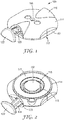
- a delivery system 100 includes a device housing 110.
- the housing 110 can be self-contained and compactly constructed to provide a relatively low profile and small footprint for, among other factors, ease of use and patient comfort.
- the housing 110 may include lower housing portion 112 and mating upper housing portion 111.
- the delivery system may include a unitary housing.
- Upper and lower housing portions 111 and 112 may be secured together by any suitable means including, but not limited to, snap-fit together or coupled by pivots, frictional interference fits, welding, heat-staking, solvent bonding, mechanical fasteners, and the like.
- Housing 110 may be made of suitable lightweight materials compatible for ease of patient and practitioner handling.
- the materials used in housing 110 may include, but are not limited to, plastics, metals, composite materials, and combinations thereof.
- the housing 110 can be made of thermoplastics such as polypropylene, polybutylene terephthalate, polystyrene, polyethylene, polythermide, polyethylene terephthalate, polystyrene, polyvinyl chloride, polymethylmethacrylate, acrylonitrile-butadiene styrene, polycarbonate, and blends thereof.
- Other possible materials include metals, such as aluminum, steel, and stainless steel.
- upper housing portion 111 may include a window 118 that allows a user to easily visually observe the operation of the elements within the cavity 116. Additionally or alternatively, the upper housing portion 111 can include transparent material to allow a user to visually inspect the application of a microneedle array.
- the housing 110 includes a cavity 116 that receives a carrier assembly 150.
- the carrier assembly 150 includes an array carrier 151 and a microneedle array 152 coupled to a surface thereof.
- the microneedle array comprises a major plane that is oriented generally parallel to a skin surface 190 (as depicted in Figure 5A ) during use of the delivery system.
- Microneedle array 152 can include one or more needle or needle-like structures as well as other structures capable of piercing the stratum corneum.
- the microneedles are typically less than 900 microns, often less than 500 microns in height, and sometimes less than 300 microns in height.
- the microneedles are typically more than 20 microns in height, often more than 50 microns in height, and sometimes more than 125 microns in height.
- a stored energy device 130 is received proximate to or within the cavity 116 near a surface of the carrier assembly 150.
- the stored energy device can also be in direct contact with a portion of the carrier assembly 150. In other embodiments, the distance between the assembly 150 and the stored energy device 130 can vary, allowing the stored energy device to travel a certain distance before contacting the assembly 150.
- microneedles useful in the various embodiments of the invention may comprise any of a variety of configurations, including but not limited to those described in the following patents and patent applications.
- One embodiment for the microneedles comprises the structures disclosed in United States Patent Application Publication No. US2003/0045837 .
- the disclosed microstructures in the aforementioned patent application are in the form of microneedles having tapered structures that include at least one channel formed in the outside surface of each microneedle.
- the microneedles may have bases that are elongated in one direction.
- the channels in microneedles with elongated bases may extend from one of the ends of the elongated bases towards the tips of the microneedles.
- the channels formed along the sides of the microneedles may optionally be terminated short of the tips of the microneedles.
- the microneedle arrays may also include conduit structures formed on the surface of the substrate on which the microneedle array is located.
- the channels in the microneedles may be in fluid communication with the conduit structures.
- Another embodiment for the microneedle devices comprises the structures disclosed in co-pending United States Patent Application Publication No. US2005/0261631 which describes microneedles having a truncated tapered shape and a controlled aspect ratio.
- Still another embodiment for the microneedles comprises the structures disclosed in United States Patent No. 6,091,975 (Daddona, et al. ) which describes blade-like microprotrusions for piercing the skin.
- Still another embodiment for the microneedles comprises the structures disclosed in United States Patent No. 6,312,612 (Sherman, et al. ) which describes tapered structures having a hollow central channel. Still another embodiment for the micro arrays comprises the structures disclosed in International Publication No. WO00/74766 (Garstein, et al. ) which describes hollow microneedles having at least one longitudinal blade at the top surface of tip of the microneedle.
- the cavity 116 can be defined by cooperation of both the upper housing 111 and the lower housing 112, or may be solely contained in the lower housing 112.
- the minimum height of the cavity 116 is at least partially determined by the desired travel distance of the microneedle array 152 before reaching the skin surface and the travel distance of the stored energy device. Accordingly, the height of cavity 116 in some embodiments may be no greater than 2 centimeters. In other embodiments, the height of the cavity 116 may be no greater than 1 centimeter, in other embodiments no greater than 8 millimeters, in yet other embodiments no greater than 5 millimeters. In certain embodiments, the height of the cavity is at least 1 millimeter, in other embodiments at least 2 millimeters, in other embodiments at least 5 millimeters. Cavities less than 1 millimeter in height may not allow sufficient travel distance for the array to pierce the stratum corneum and/or may require application of greater force to the array than safe or desirable in a low-profile device.
- Lower housing portion 112 includes a base 114, which can be generally planar, and defines an opening 115 to the cavity 116.
- the base 114 includes an attachment surface 117, which at least partially envelopes the opening 115 and can also be generally planar.
- the attachment surface 117 can include an adhesive layer 160 for eventual attachment of the housing 110 to a patient's skin surface.
- Adhesive layer 160 can be a continuous coating, a patterned coating, or discrete portions of adhesive, or combinations thereof.
- a first major surface of the adhesive can be coupled to a release liner 170 (see Fig. 3 ) prior to use.
- the height of the housing 110 may be no greater than 3 centimeters. In other embodiments, the height of the housing may be no greater than 1 centimeter, in other embodiments no greater than 5 millimeters, in other embodiments no greater than 3 millimeters. In certain embodiments, the height of the housing is at least 1.5 millimeters, in other embodiments at least 2 millimeters, in other embodiments at least 5 millimeters. Housings less than 1.5 millimeters in height may not allow sufficient travel distance for the array to pierce the stratum corneum and may be too difficult to handle. On the other end of the spectrum, housings greater than 3 centimeters in height can be unwieldy and difficult to maintain adherence to skin.
- the stored energy device 130 can be secured to the interior of the housing by any suitable attachment means, including but not limited to adhesives, fasteners, interference-fits, and the like.
- peripheral portions of the stored energy device 130 may be contained between the upper housing 111 and lower housing 112, and rested on a groove or ridge portion proximate the cavity 116 without any additional attachment.
- the stored energy device 130 is actuatable to apply force in a direction generally orthogonal to the attachment surface 117 and major plane of the array 152.
- Suitable stored energy devices include, but are not limited to, domed springs, deflected beams, coiled springs, leaf-like springs, propellant canisters, and the like. In most embodiments, a portion of the stored energy device can travel unimpeded within the housing and/or cavity to deliver the application force to the carrier assembly 150.
- the stored energy device 130 is actuatable for applying force (i.e., application energy) to carrier assembly 150, thereby accelerating at least a portion of the assembly to a velocity before impact sufficient to pierce the skin. It is desirable that a consistent, predetermined amount of force is necessary to actuate the stored energy device, thereby resulting in a consistent amount of force applied normal to the skin during actuation.
- the microneedle array 152 typically reaches a velocity before impact ranging from between about 2 and about 20 m/sec before the microneedle array impacts a patient's skin. More typically, the array strikes a patient's skin at a velocity before impact ranging from between about 4 and about 15 m/sec. In certain preferred embodiments, the velocity at impact is consistently over 10 m/sec. It can also be desirable, however, to limit the velocity to prevent or reduce the stimulation of underlying nerve tissue on or after impact.
- the stored energy device 130 is configured so that it will undergo a bifurcated (i.e., stepwise) motion in a direction generally orthogonal to the attachment surface and/or the major plane of a microneedle array.
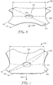
- the stored energy device in such embodiments can be a domed, bifurcating spring as depicted in Figures 6 and 7 .
- the stored energy device can also include a plurality of bifurcating springs, as depicted in Figures 9 and 11 .
- a bifurcating spring is a spring that undergoes a shape change as a result of a predetermined force applied normal to a major plane of the spring. Using methods further described herein, it is possible to manufacture bifurcating springs that can store a greater or substantially greater amount of energy than can be comfortably applied to the delivery system by a user during use.
- the undulating spring 330 includes a generally circular central portion and one or more legs 334.
- the spring 330 can include an aperture 336 proximate the center.
- the loaded spring 330 is designed to store a certain amount of potential energy. This potential energy is converted to a kinetic energy once a predetermined amount of activation energy is transferred to the first major surface 332 of the spring 330. This results in the spring bifurcating and reaching the destabilized configuration as depicted in Figure 7 .
- the release of kinetic energy occurs in a direction 338 generally orthogonal to the major plane of the spring, which results in the center of the spring traveling a certain distance between stable and destabilized states.
- the bifurcating spring 330 may release energy greater than the energy necessary to cause bifurcation (i.e., the activation energy).
- the kinetic energy i.e., application energy when transferred to a microneedle array or carrier assembly
- the application energy is 4 times greater than the activation energy, in other embodiments, at least 10 times, and in yet other embodiments at least 20 times greater than the activation energy.
- the bifurcating spring is potentially capable of releasing substantially more energy the amount of normal force applied to the skin can be minimized while generating sufficient application velocity and the user to user variability in force applied to the carrier assembly is reduced. This reduced variability can result in more consistent and repeatable microneedle penetration.
- a bifurcating spring according to the present disclosure may be created by, e.g., applying a predetermined force (i.e., load) to the center of an otherwise non-bifurcating domed spring, while supporting the periphery.
- Suitable non-bifurcating springs include but are not limited to stainless steel domed springs available from Snaptron Inc., Windsor, CO.
- the force applied to a spring surface is preferably sufficient to cause plastic deformation of at least a portion of the spring.
- a press or probe applies a displacement to a surface 332 of the spring at a constant rate. The press continues past the point of bifurcation and until the desired force has been applied after bifurcation.
- both the load applied after bifurcation and the time over which the load is applied appear to be positively correlated with the energy necessary to activate the spring, and to a lesser degree, the potential energy released on bifurcation. After a certain time, however, an increase in hold time may not amount to an appreciable increase in stored energy.
- the energy applied after activation of the spring is further influenced by, inter alia, the material of the spring, the thickness of the material, and the geometry of the dome.
- the housing 110 further includes an actuator 120.
- the actuator 120 cooperates with the stored energy device 130 to form an applicator device.
- the actuator 120 includes a finger engageable portion 122 that is adapted to cover actuator opening 123 formed in the upper housing portion 111.
- the actuator further includes an extended arm portion 124 that extends from finger engageable portion 122 through opening 123 and into the cavity 116.
- the arm portion 124 can include a wedge 126 or other protrusion.
- the actuator 120 is movable within the housing at an angle relative to the attachment surface 117. Movement of the wedge 126 relative to the stored energy device 130 applies a force in a direction generally orthogonal to the major plane of the array 152.
- the actuator may not actually contact the stored energy device 130, but can remove an impediment to the release of kinetic energy.
- the actuator may engage and deform a releasable retaining device that holds the stored energy device in a primed position. Deformation or displacement of the releasable retaining device may then allow the stored energy device to discharge the potential energy stored therein.
- carrier assembly 150 includes a solid microneedle array 152, an array carrier 151, and a flexible membrane 140.
- the microneedle array 152 can be attached to a first surface of array carrier 151 by any suitable attachment means.
- the attachment means is an adhesive 157, which may be in the form of a continuous coating, a patterned coating, or discrete portions of adhesive.
- the adhesive attachment is non-permanent, that is, after application of the microneedle array, the carrier may be removed from the skin surface though all or part of the array remains.
- microneedle device 152 and the array carrier 151 include snap-fit connections, hook and loop (e.g., VelcroTM) attachments, magnetic attachment, heat bonding, welding, or any other suitable conventional attachment method known to one of ordinary skill in the art.
- the microneedle array may be formed or molded as an integral portion of the array carrier 151.
- microneedle array 152 depicted in Figure 2 has a hexagonal shape, but any of a number of shapes and sizes are suitable for use with application devices of the present invention.
- At least a portion of t the array carrier 151 can be formed so as to be relatively rigid.
- Suitable materials include polymers, such as liquid crystal polymers, polypropylene, polybutylene terephthalate, polystyrene, polyethylene, polythermide, polyethylene terephthalate, polystyrene, polyvinyl chloride, polymethylmethacrylate, acrylonitrile-butadiene styrene, polycarbonate, and blends thereof.
- the rigidity can provide support for the microneedle array and may assist in the transfer of application energy.
- Other materials are also contemplated, including metals, ceramics, and other materials that will be apparent to those skilled in the art.
- the array carrier can be comprised of the same material as the microneedles of the microneedle array.
- the carrier assembly 150 includes a flexible membrane 140 coupled to a surface of the array carrier 151 opposite the microneedle array 152 via attachment mechanism 158.
- the flexible membrane 140 includes a chamber having a bellowed height 142.
- the bellowed height 142 is preferably such that the carrier assembly 150 is retained in contact with or in close proximity to a portion of the stored energy device 130 when received in the cavity 116.
- the flexible membrane 140 is preferably capable of retaining the bellowed height 142 prior to the application of force to the carrier assembly 150 via the stored energy device.
- the membrane can be constructed of CoTran 9701 polyurethane film, available from 3M Company, St. Paul, MN. Other polymeric films capable of maintaining the bellowed height are also suitable for use as a membrane.
- the flexible membrane includes a material that is sterilizable and/or maintains a sterile barrier.
- the flexible membrane 140 can be vented or non-vented.
- a chamber of air may be formed between the skin surface, the adhesive 160, the membrane/array assembly, and potentially a portion of the lower housing 112.
- a membrane is "vented" when it includes deliberate apertures or channels to allow the flow of fluid out of the chamber.
- at least a portion of the membrane is non-vented, in that is does not include any deliberate means for fluid to flow out of the chamber.
- Non-vented membranes may surprisingly provide better depth of microneedle penetration in the skin, as well as more consistent penetration levels across the entire array.
- a non-vented membrane may allow for a carrier assembly to be provided pre-sterilized and pre-loaded with the agent intended for transdermal delivery.
- the carrier assembly 150 may be secured within the cavity 116 via attachment of the flexible membrane 140.
- a certain length of the flexible membrane 140 can be secured via attachment mechanism 145 to portions of the lower housing 112 proximate the opening 115.
- the chamber can be sized to create an interference fit with cavity 116, such that the carrier assembly 150 may simply be pressed into the housing.
- the carrier assembly 150 can also be coupled or releasably coupled to the stored energy device 130.
- the stored energy device 130 may include one or more apertures and array carrier 151 can include one or more elongated protrusions capable of being received in the apertures. Once so received, the protrusion may be riveted to the stored energy device 130.
- the carrier assembly 150 may be secured to the stored energy device 130 via adhesive or other attachment means described herein.
- the motion of the microneedle array is coupled to that of the spring.
- both the spring and carrier assembly will move cooperatively towards the skin surface in the direction of the applied force. Impact of the assembly at the skin surface will also cause the skin to move in the direction of the applied force.
- the spring reaches a point of maximum extension and will begin to travel away from the skin (i.e., recoil). The surface of the skin, however, may continue to move in the direction of the applied force. Since they are coupled to motion of the spring, the microneedles may stop penetrating or even pull out of the skin, leading to less and/or more inconsistent depth of penetration.
- the stored energy device 130 is not attached or otherwise fixed to the carrier assembly 150. As such, following impact at the skin, the stored energy device 130 may freely recoil upwardly and vibrate without otherwise affecting the travel of the carrier assembly/microneedle array. Since the carrier assembly 150 is not attached to the stored energy device 130 after activation, it is free to continue moving forward with the motion of the skin; without regard to the recoil of the stored energy device 130. This independent motion may reduce the tendency for the microneedles to stop penetrating or to be pulled out of the skin. Increased depth and more consistent penetration of the microneedles can result in improved delivery across the stratum corneum.
- the carrier assembly 150 can also be coupled to the housing 110 or cavity 116 without use of a flexible membrane 140 and without attachment to the stored energy device 130.
- the array carrier can include protrusions that rest on an internal ridge or groove, providing an inference fit that allows for release of the carrier assembly upon application of minimal force.
- the delivery system 100 may be provided to a practitioner or user fully assembled and/or coated with the agent to be delivered to the skin.
- the carrier assembly is provided separately from the housing.
- the stored energy device is provided in the loaded configuration, though it is also possible for the stored energy device to be primed after receipt or shortly before use.
- the present disclosure further provides for methods of delivering a microneedle array to a patient's skin surface.
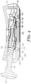
- One method of delivering a microneedle array using decoupled delivery system 100 is depicted in Figures 5A-5C .
- the attachment surface 117 is placed proximate a patient's skin surface 190.
- a force may be applied to finger engageable portion 122 of the actuator 120. This force is typically applied in a direction 200 that is generally parallel to major plane of array and the attachment surface 117.
- the applied force moves the wedge 126 relative to the stored energy device, resulting in the application of force orthogonal to the major plane of the stored energy device 130.
- This application of force causes a transfer of energy (i.e., activation energy) to the stored energy device 130.
- the stored energy device releases its potential energy, accelerating a portion of the device 130 towards the carrier assembly 150.
- the force required to release the potential energy is the stored energy device is no greater than 15 N, in some embodiments no greater than 8 N, and in some embodiments no greater than 5 N, and in yet other embodiments no greater than 1 N. In certain circumstances, it may be preferred that the force required be at least 2 N and no greater than 5 N. While it may be advantageous to reduce or minimize activation force, it will be appreciated by those skilled in the art that the activation force should be high enough to avoid inadvertent firing of the stored energy device before the user is ready to use the delivery system.
- the stored energy device 130 In releasing its potential energy, at least a portion of the stored energy device 130 travels in the direction of the skin surface.
- the stored energy device 130 will contact the carrier assembly 150, applying a force in a direction 220 generally orthogonal to the major plane of the microneedle array 152.
- the energy applied by the stored energy device is no greater than 0.3 J, in some embodiments no greater than 0.2 J, and in some embodiments no greater than 0.15 J, and in yet other embodiments no greater than 0.1 J.
- the energy applied by the stored energy device is at least 0.006 J, in some embodiments at least 0.01 J, and in some embodiments at least 0.05 J.
- the force applied be at least 0.013 J and no greater than 0.12 J.
- This transfer of the application energy accelerates the carrier assembly 150 including the membrane 140 in the direction of the skin, with the assembly eventually emerging through opening 115.
- the application energy is at least twice the activation energy, in other circumstances at least 5 times the activation energy, in other embodiments at least 10 times the activation energy, in yet other embodiments at least 20 times the activation energy, and in yet other embodiments at least 30 times the activation energy.
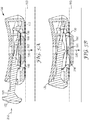
- Figure 5B depicts the delivery system 100 at a time after the microneedle array 152 has impacted the skin.
- the motion of the stored energy device 130 slows relative to the motion of the carrier assembly 150 and a measureable gap 230 may form between them.
- this gap may form and close one or more times before the stored energy device, carrier, and skin come to rest.
- the microarray, skin, and membrane continue to move in the direction 220 of the application force. Since the motion is decoupled, however, the carrier assembly 150 is free to move with the skin until the skin's point of maximum extension.
- the membrane is capable of traveling a greater distance than the carrier assembly would travel due to the energy applied by the stored energy device 130.
- the length of membrane 140 received in the cavity 116, and the resultant bellowed height 142, can be accordingly designed to allow the membrane 140 to extend substantially beyond the attachment surface 117 of the housing 110.
- the skin and carrier assembly 150 will begin to recoil and dampen.
- the carrier assembly may come to rest within the cavity 116, with substantially no portion thereof, with the exception of the microneedles, emerging from opening 115.
- the membrane 140 does not return to its original bellowed height 142, leaving room in the cavity 116 for the "fired" stored energy device and allowing the microneedles to remain at the desired penetration depth.
- at least a portion of the array carrier 151 can emerge from the housing.
- delivery system 100 can be activated without creating a significant skin dome and without substantially stretching the skin or otherwise disturbing the surface.
- the delivery system does not create a skin dome or stretch the skin.
- a small activation force in a direction orthogonal to the skin may be necessary to activate the stored energy device
- the forces generated normal to the skin surface are essentially reacted against one another within the housing 110. Accordingly, the force actually applied to the skin in a direction normal to the plane of the skin is zero or near zero.
- the forces generated in a direction parallel to the plane of the skin in this embodiment are at least substantially transferred to the stored energy device as the wedge 126 slides across a surface thereof.
- the efficacy of the parallel sliding motion of the actuator will likely discourage the user from pushing the device in a direction normal to the skin during activation, further increasing the consistency of application.
- an actuator movable in direction generally parallel to the attachment surface may allow the activation force of the stored energy device to be set at a higher level, while maintaining a relatively low force required to be applied by the user. This may be particularly useful, as high activation forces can limit the patient population that can operate a particular delivery system.
- the parallel motion of the actuator may further reduce the variability in velocity of the array at impact.
- FIGS 8-11 depict additional implementations of a delivery system according to the present disclosure, particularly those featuring alternative actuators. Except as set out in the paragraphs that follow, the delivery systems 800 and 900 are substantially the same as the apparatus 100 described above and consequently a description of the similar aspects need not be repeated.
- the delivery system 800 features a rotatable actuator 820 positioned above a stored energy device 830.
- the rotatable actuator 820 rotates about an axis of rotation 821 that is generally perpendicular to the major plane of the array 852. In other embodiments not depicted herein, the actuator 820 is configured to rotate about an axis angularly offset from axis 821.
- the rotatable actuator 820 includes helical threads 823 and a graspable ridge 822 on an exterior surface thereof.
- the upper housing 811 includes an aperture 870 located above the cavity 816 and stored energy device 830.
- the aperture 870 has one or more side wall portions including helical grooves 873 that correspond to the helical threads on the actuator 820.
- the rotation of the actuator 820 about the axis 821 brings an engagement surface 824 closer to the stored energy device 830.
- the actuator 820 may thus be rotated by a user until the engagement surface 824 contacts the stored energy device 830, eventually resulting in application of the predetermined activation force orthogonal to the major plane of the stored energy device 830 without substantial normal force applied to the skin.
- Figure 10 and 11 depict a microneedle delivery system 900 featuring a different rotatable actuator.
- Actuator 920 comprises a cam rotatable about an axis 921. Rotation of the actuator 920 transfers a force orthogonal to the major plane of the stored energy device 930 and/or the microneedle array 952.
- the delivery systems 800 and 900 may also provide the potential benefits as described above, since equal and opposite forces react within the device leading to no or essentially no force being applied normal to the skin during activation.
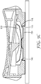
- the delivery system 1000 includes a housing 1010 having a cavity 1016 defined therein; a stored energy device 1030 received in or proximate to the cavity; and a carrier assembly including a microneedle array 1052 coupled to an array carrier 1051.
- An upper housing portion 1011 includes an attachment cap 1070 received in a central aperture 1019.
- the attachment cap 1070 can be secured to the upper housing via releasable or other adhesive, interference fit, or other means known to those having skill in the art.
- Suitable materials for the attachment cap include thermoplastic elastomers, silicones, rubber, and other materials known to one skilled in the art.
- the attachment cap 1070 receives the distal end of an elongated arm portion 1053 of the array carrier 1051.
- the end of the elongated arm portion is press fit into aperture 1019 without an attachment cap 1070.
- the arm portion 1053 also extends through an aperture in the center of stored energy device 1030.
- the arm portion 1053 is designed so that it may be press fit into the attachment cap 1070, while not engaging the periphery of the stored energy device aperture 1032 (i.e., the dimension of the aperture are greater than those of the distal end of the arm portion 1053).
- the proximal end of the arm portion 1053 may be configured for an interference fit with the aperture 1032, obviating the need for the attachment cap.
- the attachment cap and an interference fit between carrier and stored energy device can be used.
- An actuator 1020 includes one or more posts 1022 extending from a generally planar base 1021.
- the posts 1022 extend through apertures 1013 in the upper housing into the cavity 1016 proximate to or in contact with the stored energy device 1030.
- the base 1021 also includes a center pedestal 1024 designed to engage attachment cap 1070 and/or arm portion 1053.
- the actuator 1020 may be provided already received housing 1010 or as a separate component.
- FIG. 14 One potential method of using the delivery system 1000 is depicted in Figure 14 .
- a user places actuator 1020 within the apertures in upper housing 1011.
- a force in a direction 1080 normal to the base 1021 and the attachment surface 1017 is then applied.
- the center pedestal 1024 pushes the attachment cap 1070 down to a point where it releases from the upper housing 1011 and is free to move independently of the housing 1010.
- the posts 1022 then engage the stored energy device 1030, transferring the activation energy thereto.
- the length of the posts 1022 can be designed so that the attachment cap 1070 (or arm portion 1053) is released first, followed by transfer of energy to the stored energy device 1030.
- the attachment cap 1070 or arm portion 1053 is released and the stored energy device 1030 is activated at essentially the same time.
- the application energy transferred to the carrier assembly is sufficient to dislodge the arm portion 1053 from the attachment cap 1070 or the attachment cap 1070 from the housing.
- portions of the attachment cap 1070 can expand upon application of pressure via the pedestal 1024, releasing the arm portion 1053 while the attachment cap 1070 remains essentially in place.
- the stored energy device 1030 will contact the carrier assembly, applying a force in a direction 1080 generally orthogonal to the major plane of the microneedle array 1052. This transfer of the application energy accelerates the carrier assembly in the direction of the skin, with the assembly eventually emerging through opening on the bottom of housing 1010.
- the central pedestal 1024 may continue to push the arm portion 1053 towards the skin, potentially resulting in increased penetration depth.
- the geometry of the actuator 1020 can be adjusted such that the bottom face of the base 1021 is nearly in contact with the top surface of the upper housing at the time the stored energy device is actuated. In such an embodiment, the total distance that the housing 1010 can rebound away from the skin is limited due to the presence of a user's finger pushing down on the actuator 1020.
- the actuator 1020 can be designed to provide clearance between the bottom surface of the base 1021 and the top of the upper housing at the time of actuation, which would allow the housing 1010 to move a certain distance away from the skin as the stored energy device 1030 releases its potential energy.
- Microneedle arrays suitable for use in the present disclosure may be used to deliver drugs (including any pharmacological agent or agents) through the skin in a variation on transdermal delivery, or to the skin for intradermal or topical treatment, such as vaccination.
- drugs that are of a large molecular weight may be delivered transdermally.
- Increasing molecular weight of a drug typically causes a decrease in unassisted transdermal delivery.
- Microneedle arrays suitable for use in the present delivery systems have utility for the delivery of large molecules that are ordinarily difficult to deliver by passive transdermal delivery. Examples of such large molecules include proteins, peptides, nucleotide sequences, monoclonal antibodies, DNA vaccines, polysaccharides, such as heparin, and antibiotics, such as ceftriaxone.
- microneedle arrays suitable for use in the present invention may have utility for enhancing or allowing transdermal delivery of small molecules that are otherwise difficult or impossible to deliver by passive transdermal delivery.
- molecules include salt forms; ionic molecules, such as bisphosphonates, preferably sodium alendronate or pamedronate; and molecules with physicochemical properties that are not conducive to passive transdermal delivery.
- microneedle arrays suitable for use in the present delivery system may have utility for enhancing delivery of molecules to the skin, such as in dermatological treatments, vaccine delivery, or in enhancing immune response of vaccine adjuvants.
- the drug may be applied to the skin (e.g., in the form of a solution that is swabbed on the skin surface or as a cream that is rubbed into the skin surface) prior to or after applying the microneedle array.
- the drug or fluid may be applied directly to the microneedles.
- the delivery system may be used for creating microprotrusions in the skin.
- the delivery systems may be used for immediate delivery, that is where they are applied and immediately removed from the application site, or they may be left in place for an extended time, which may range from a few minutes to as long as 1 week.
- an extended time of delivery may from 1 to 30 minutes to allow for more complete delivery of a drug than can be obtained upon application and immediate removal.
- an extended time of delivery may be from 4 hours to 1 week to provide for a sustained release of drug.
- Example 1 Two different fully assembled delivery systems were evaluated. For Example 1, a decoupled delivery system of the design described in Figures 1-5A-C and containing one spring was used. For Example 2, a decoupled delivery system of the design described in Figures 12-14 and containing three springs was used.
- the housing components of the delivery systems were fabricated from ACCURA60 plastic (3D Systems, Rock Hill, SC) using a stereolithographic process.
- the external housing dimensions for Example 1 were 34.0 mm (diameter) by 9.4 mm (overall height).
- the opening in the housing for the array was 16.0 mm in diameter.
- Example 2 The external housing dimensions for Example 2 were 27.0 mm (diameter) by 8.0 mm (overall height excluding the actuator component). The opening in the housing for the array was 14.0 mm in diameter.
- the bifurcated springs were four-legged domed springs (Snaptron, Windsor, CO) prepared from 301 full-hard stainless steel. As depicted in Figure 6 , the springs had a circular shape with four equally spaced and sized cut-out sections that were shaped as continuous arcs.
- the diameter (L1) of the springs was 20.2 mm.
- Each of the four leg regions formed by the cut-outs was 4.4 mm as measured along the outer edge of the leg (L2).
- the distance across and through the center of the springs at the narrowest point was 15.0 mm (L3).
- a 3.2 mm diameter hole was positioned in the center of the springs.
- the height of the domed springs before bifurcation and conditioning was 2.3 mm.
- the stock thickness of the domed springs before forming was 0.20 mm.
- the diameter (L1) of the springs was 20.4 mm.
- Each of the four leg regions formed by the cut-outs was 3.9 mm as measured along the outer edge of the leg (L2).
- the distance across and through the center of the springs at the narrowest point was 13.7 mm (L3).
- a 3.2 mm diameter hole was positioned in the center of the springs.
- the height of the domed springs before bifurcation and conditioning was 1.8 mm.
- the stock thickness of the domed springs before forming was 0.18 mm.
- the springs of Examples 1 and 2 were bifurcated and the activation energy level was set by the following spring conditioning process.
- the center of the single spring of Example 1 was displaced from its resting geometry at a rate of 0.1 mm/second through a bifurcation point until reaching a maximum displacement force of 3000 g after bifurcation.
- the spring was held at the maximum displacement force for 30 seconds before releasing the applied load.
- the targeted stored potential energy of the 1-spring system was 0.059 J.
- the center of each spring was displaced from its resting geometry at a rate of 0.1 mm/sec through a bifurcation point until reaching a maximum displacement force of 1500 g after bifurcation.
- Each spring was held at the maximum displacement force for 30 seconds before releasing the applied load.
- the targeted stored potential energy of the 3-spring system was 0.048 J.
- the spring conditioning procedures were designed to provide a spring or set of springs that produced a total targeted activation force of 350-400 g.
- the flexible membrane in the delivery system of Example 1 was about 25.2 mm in diameter and was constructed from CoTran 9701 polyurethane film (3M Company, St. Paul, MN) having an initial film thickness of 2 mil. A film stretching procedure was used to create the bellowed membrane.
- the membrane was attached to both the lower housing (of an unassembled device) and the array carrier using a continuous coating of 3M Double Coated Medical Tape 1513 (3M Company, St. Paul, MN).
- the lower housing was simply supported at its perimeter and the membrane film was stretched by displacing the array carrier a distance of 12 mm at a rate of 0.5 mm/second and holding at its maximum displacement for 30 seconds.
- the assembly of the delivery system was completed by attaching the remaining components and positioning the now bellowed membrane with the attached array carrier in the cavity of the housing.
- the microneedle array was molded as an integral portion of the array carrier using either LEXAN HPSIR-1125 polycarbonate (PC) (GE Plastics, Pittsfield, MA) or VECTRA MT 1300 thermoplastic liquid crystal polymer (LCP) (Ticona Engineering Polymers, Florence, KY).
- the microneedle array featured four-sided pyramidal shaped microneedles having heights of about 500 microns. Each microneedle was formed having a base width of about 167 microns and a tip width of about 10 microns.
- the microneedles were oriented in an octagon shaped pattern of about 471 microneedles with equal spacing between individual microneedles of about 550 microns (as measured from tip to tip).
- the array carrier featured a circular shaped base with a diameter of 13.4 mm.
- the microneedle array was molded as an integral portion of the array carrier using LEXAN HPSIR-1125 polycarbonate (PC).
- the PC microneedle array featured four-sided pyramidal shaped microneedles having heights of about 250 microns. Each microneedle was formed having a base width of about 83 microns and a tip width of about 10 microns.
- the microneedles were oriented in an octagon shaped pattern of about 1288 microneedles with equal spacing between individual microneedles of about 275 microns (as measured from tip to tip).
- the array carrier featured a circular shaped base with a diameter of 12.7 mm.
- the array carrier also included an elongated arm 2.8 mm in diameter and 6.3 mm in length.
- the final resting position of the base of the microneedle array extended beyond the base of the lower housing by a distance of 0.11 mm for Example 1, and a distance of 0.08 mm for Example 2.
- DOP depth of penetration
- step two the arrays were flood coated with 60 ⁇ l of an aqueous solution of 33.3 mg/ml aluminum potassium sulfate (Penta Manufacturing, Livingston, NJ) and then dried at 35 °C for 30 minutes.
- step three the primed arrays were flood coated with 60 ⁇ l of an aqueous solution of 0.08% (weight/volume) Rhodamine B (Sigma-Aldrich, St. Louis, MO) and then dried at 35 °C for 30 minutes.
- the ham area of the pig was selected as the application site.
- the ham area was first trimmed with an electric clipper followed by shaving with a razor and shaving cream.
- the ham was then rinsed with deionized water and wiped with 70/30 isopropanol water.
- the animals were anesthetized with isoflurane gas and maintained under anesthesia throughout the experiment.
- a fully assembled delivery system as described for Example 1 was applied to the skin on the ham area of a pig with 3M Double Coated Medical Tape 1513. The delivery system was actuated, maintained on the animal for 15 minutes, and then removed.
- the depth of penetration into the pig skin was determined indirectly by measuring the distance from the tip of the microneedle to where the Rhodamine B coating was wiped or dissolved from the microneedle after application into the skin. The measurement was conducted using a Nikon LV-100 microscope at 100X magnification (Nikon Instruments, Melville, NY) with Image Pro® Plus digital image analysis software (Media Cybernetics, Bethesda, MD). For each microneedle array type (PC or LCP), three animals were tested. The mean DOP was determined by sampling a subset of 72 microneedles from each array. Each array pattern was divided into four quadrants and relatively equal numbers of microneedles were sampled from each quadrant. In Table 1, the results are reported from the microneedle DOP study. Table 1. Depth of Microneedle Penetration into Pig Skin Composition of Microneedle Array Mean Microneedle Depth of Penetration (microns) Standard Deviation (microns) %RSD PC 113 14 12% LCP 141 42 30%
- Example 2 A fully assembled microneedle array delivery system as described in Example 2 was used in a tetanus toxoid immunization study.
- microneedle arrays described above were dip-coated (procedures to dip coating provided in United States Patent Application Publication No. US2008/0051699 (Choi, et al. )) with a formulation containing tetanus toxoid (Statens Serum Institute, Copenhagen, Denmark), sucrose (30%), hydroxyethyl cellulose (1%), and PBS buffer.
- the coated arrays were dried in an oven for 30 minutes at 35 °C.
- the dried arrays were sealed in pouches with a foil-laminate moisture barrier and stored at 5 ⁇ 3 °C. Prior to attaching to the assembly carrier, the arrays were equilibrated to ambient conditions (21 °C and 45% relative humidity).
- the coated arrays were attached to the array carriers of the delivery systems using 3M Double Coated Medical Tape 1513 at a time point of 3 hours or less before the start of the animal experiments.
- a reverse phase HPLC assay was used to determine the tetanus toxoid content (in micrograms (mcg)) on the coated microneedle arrays.
- the dose of tetanus toxoid delivered to the animals was calculated by measuring the difference between the initial tetanus toxoid content on the arrays and the residual tetanus toxoid on the arrays after administration to the animals.
- the male, hairless guinea pigs (obtained from Charles River Laboratories, Wilmington, MA) were approximately nine months old and weighed between 800 to 1000 g at the beginning of the study. A total of five animals were dosed on day 1 and on day 28 of the study. Anesthetized animals were dosed by attaching the fully assembled delivery system of Example 2 to the skin on the abdomen of the animal with 3M Double Coated Medical Tape 1513. The delivery system was actuated and maintained on the skin of the animal for 5 minutes. The mean value for the amount of tetanus toxoid coated on the arrays (mcg/array) and the mean calculated dose given to each animal (mcg/animal) is reported in Table 2.
- Example 2 3.2 mcg/array 1.6 mcg/animal 1.5 mcg/animal
- Blood draws were conducted on anesthetized animals on days 28 and 56 of the study.
- the serum was separated and analyzed for anti-tetanus toxoid IgG using a mid-point tittering ELISA assay.
- the assay was standardized using NIBSC Code 98/572 Diptheria and Tetanus Antitoxin Guinea Pig Serum obtained from the National Institute for Biological Standards and Control (Hertfordshire, England).
- the anti-tetanus toxoid IgG titer was expressed in ELISA units with 20 ELISA units being equivalent to a measured IgG level of 0.2 IU/mL. Animals with IgG titers greater than 20 ELISA units were determined to be seroconverted.
- Table 3 the anti-tetanus toxoid IgG titer values on days 28 and 56 of the study are reported for each of the five animals. On day 28 (after one dose), three of the five animals were seroconverted. On day 56 (after two doses), all five animals were seroconverted. Table 3: Anti-Tetanus Toxoid IgG Titer Values Animal Number ELISA Units Measured Day 28 Elisa Units Measured Day 56 1 19 167 2 67 678 3 106 1650 4 44 453 5 5 152
Landscapes
- Health & Medical Sciences (AREA)
- Engineering & Computer Science (AREA)
- Dermatology (AREA)
- Medical Informatics (AREA)
- Anesthesiology (AREA)
- Biomedical Technology (AREA)
- Heart & Thoracic Surgery (AREA)
- Hematology (AREA)
- Life Sciences & Earth Sciences (AREA)
- Animal Behavior & Ethology (AREA)
- General Health & Medical Sciences (AREA)
- Public Health (AREA)
- Veterinary Medicine (AREA)
- Media Introduction/Drainage Providing Device (AREA)
- Infusion, Injection, And Reservoir Apparatuses (AREA)
Claims (13)
- Système intégré (100) pour poser un ensemble de micro-aiguilles (152), le système comprenant :un boîtier (110) ayant une cavité (116) à l'intérieur de ce dernier, et comprenant un dispositif d'application ;un ensemble de support (150) comprend un ensemble de micro-aiguilles solides (152), un support d'ensemble (151) et une membrane souple (140), dans lequel une partie de l'ensemble de support (150) est fixée sur le boîtier (110) à proximité de la cavité (116) et est en contact avec une partie du dispositif d'application,dans lequel ni l'ensemble de support (150), ni l'ensemble (152) n'est fixé au dispositif d'application, et dans lequel la membrane souple (140) est couplée à une surface du support d'ensemble (151) opposée à l'ensemble de micro-aiguilles (152) via un mécanisme de fixation (158) ;dans lequel le dispositif d'application comprend :
un dispositif à énergie stockée (130) comprenant un ou plusieurs ressorts de bifurcation (330) qui peuvent subir un changement de forme en raison d'une force prédéterminée normale par rapport à un plan majeur du dispositif à énergie stockée (130), dans lequel au moins une partie du dispositif à énergie stockée (130) est positionnée dans le boîtier (110), et dans lequel le dispositif à énergie stockée (130) peut être actionné pour appliquer la force sur l'ensemble de support (150). - Système selon la revendication 1, dans lequel la membrane (140) comprend une hauteur à soufflet supérieure à 500 microns et inférieure à 1 cm.
- Système selon la revendication 1 ou 2, dans lequel la membrane (140) ne comporte pas d'évents.
- Système selon la revendication 1 ou 2, dans lequel la membrane (140) comprend des évents ou des ouvertures.
- Système selon l'une quelconque des revendications 1 à 4, dans lequel la membrane (140) comprend un film polymère.
- Système selon l'une quelconque des revendications 1 à 4, dans lequel la membrane (140) comprend un matériau pouvant être stérilisé.
- Système selon l'une quelconque des revendications précédentes, dans lequel le dispositif d'application comprend un actionneur (120).
- Système selon la revendication 7, dans lequel l'actionneur (120) est mobile dans le boîtier (110) dans une certaine direction sensiblement parallèle au plan majeur du dispositif à énergie stockée (130).
- Système selon la revendication 7, dans lequel l'actionneur (120) est mobile dans le boîtier (110) dans une certaine direction orthogonale au plan majeur du dispositif à énergie stockée (130).
- Système selon les revendications 7 à 9, dans lequel l'actionneur (120) est couplé, de manière coulissante, au boîtier (110).
- Système selon la revendication 8, dans lequel l'actionneur (120) comprend un bras allongé et au moins une saillie, dans lequel une partie de l'actionneur (120) est à l'extérieur du boîtier (110), et dans lequel le bras allongé peut fonctionner pour transférer l'énergie au dispositif à énergie stockée (130) via la saillie.
- Système selon la revendication 9, dans lequel l'actionneur (120) comprend une vis reçue dans une série de filetages hélicoïdaux dans le boîtier (110).
- Système selon les revendications 1 à 12, dans lequel le boîtier (110) a une hauteur d'au moins 2 mm et non supérieure à 3,0 cm.
Applications Claiming Priority (2)
| Application Number | Priority Date | Filing Date | Title |
|---|---|---|---|
| US201161546340P | 2011-10-12 | 2011-10-12 | |
| PCT/US2012/059273 WO2013055638A1 (fr) | 2011-10-12 | 2012-10-09 | Système de pose d'un ensemble de micro-aiguilles intégrées |
Publications (4)
| Publication Number | Publication Date |
|---|---|
| EP2766066A1 EP2766066A1 (fr) | 2014-08-20 |
| EP2766066A4 EP2766066A4 (fr) | 2015-08-26 |
| EP2766066B1 true EP2766066B1 (fr) | 2020-12-02 |
| EP2766066B8 EP2766066B8 (fr) | 2021-01-20 |
Family
ID=48082330
Family Applications (1)
| Application Number | Title | Priority Date | Filing Date |
|---|---|---|---|
| EP12840675.8A Active EP2766066B8 (fr) | 2011-10-12 | 2012-10-09 | Système de pose d'un ensemble de micro-aiguilles intégrées |
Country Status (9)
| Country | Link |
|---|---|
| US (1) | US10010707B2 (fr) |
| EP (1) | EP2766066B8 (fr) |
| JP (1) | JP6126105B2 (fr) |
| KR (1) | KR102022574B1 (fr) |
| CN (1) | CN103874518A (fr) |
| AU (1) | AU2012323392A1 (fr) |
| CA (1) | CA2851606C (fr) |
| IN (1) | IN2014CN02643A (fr) |
| WO (1) | WO2013055638A1 (fr) |
Families Citing this family (17)
| Publication number | Priority date | Publication date | Assignee | Title |
|---|---|---|---|---|
| CN103764197B (zh) | 2011-09-07 | 2017-03-15 | 3M创新有限公司 | 用于中空微针阵列的递送系统 |
| EP2906285B1 (fr) | 2012-10-10 | 2019-06-12 | 3M Innovative Properties Company | Applicateur d'application d'un dispositif à micro-aiguilles à la peau |
| WO2014058746A1 (fr) | 2012-10-10 | 2014-04-17 | 3M Innovative Properties Company | Applicateur régulé par une force pour appliquer un dispositif à micro-aiguille sur la peau |
| CN104797287B (zh) | 2012-11-16 | 2017-12-26 | 3M创新有限公司 | 力控施用装置 |
| CA2982803C (fr) * | 2015-04-07 | 2023-02-28 | Lts Lohmann Therapie-Systeme Ag | Systeme a microaiguilles pour l'application de formulations liquides |
| KR20220136486A (ko) * | 2016-04-29 | 2022-10-07 | 소렌토 쎄라퓨틱스, 인코포레이티드 | 미세바늘 어레이 조립체, 약물 전달 장치 및 넓은 지역에 걸쳐 액체를 저압으로 투약하는 방법 |
| KR102590629B1 (ko) | 2016-12-16 | 2023-10-19 | 소렌토 쎄라퓨틱스, 인코포레이티드 | 유체 전달 장치용 어플리케이션 디바이스 및 그 이용 방법 |
| DE102017117784A1 (de) * | 2017-08-04 | 2019-02-07 | Lts Lohmann Therapie-Systeme Ag | Applikatorsystem enthaltend ein Mikronadelarray aufweisend einen Wirkstoff für die Wundheilung |
| BR112020012557A2 (pt) * | 2017-12-19 | 2021-03-30 | Kindeva Drug Delivery L.P. | Aplicador de micromatriz |
| WO2019166572A1 (fr) | 2018-02-28 | 2019-09-06 | Pharming Intellectual Property B.V. | Système pharmaceutique pour l'administration transdermique d'un inhibiteur de la c1 estérase |
| DE102019200561A1 (de) * | 2019-01-17 | 2020-07-23 | Lts Lohmann Therapie-Systeme Ag | Träger |
| KR102368260B1 (ko) * | 2020-01-09 | 2022-03-02 | 연세대학교 산학협력단 | 마이크로니들 어플리케이터 |
| US11389632B2 (en) | 2020-12-21 | 2022-07-19 | Mediccene Inc. | Intradermal drug delivery device |
| US11654270B2 (en) | 2021-09-28 | 2023-05-23 | Biolinq Incorporated | Microneedle enclosure and applicator device for microneedle array based continuous analyte monitoring device |
| US11964121B2 (en) | 2021-10-13 | 2024-04-23 | Satio, Inc. | Mono dose dermal patch for pharmaceutical delivery |
| US11877848B2 (en) | 2021-11-08 | 2024-01-23 | Satio, Inc. | Dermal patch for collecting a physiological sample |
| KR20240048875A (ko) | 2022-10-07 | 2024-04-16 | 한미약품 주식회사 | 용해성 마이크로니들 어레이 및 이의 제조방법 |
Family Cites Families (44)
| Publication number | Priority date | Publication date | Assignee | Title |
|---|---|---|---|---|
| EP0914178B1 (fr) | 1996-06-18 | 2003-03-12 | Alza Corporation | Dispositif d'amelioration d'apport ou d'echantillonnage d'agents transdermiques |
| DK0957972T3 (da) | 1996-12-20 | 2003-07-21 | Alza Corp | Anordning og fremgangsmåde til at forøge transdermal middelflux |
| US6091975A (en) | 1998-04-01 | 2000-07-18 | Alza Corporation | Minimally invasive detecting device |
| AU2005200910B2 (en) | 1999-06-04 | 2006-08-03 | Georgia Tech Research Corporation | Devices and methods for enhanced microneedle penetration of biological barriers |
| US6743211B1 (en) | 1999-11-23 | 2004-06-01 | Georgia Tech Research Corporation | Devices and methods for enhanced microneedle penetration of biological barriers |
| US6312612B1 (en) | 1999-06-09 | 2001-11-06 | The Procter & Gamble Company | Apparatus and method for manufacturing an intracutaneous microneedle array |
| US6379324B1 (en) | 1999-06-09 | 2002-04-30 | The Procter & Gamble Company | Intracutaneous microneedle array apparatus |
| JP4633234B2 (ja) | 2000-07-04 | 2011-02-16 | 本田技研工業株式会社 | センサ機能の故障診断方法 |
| KR20030068136A (ko) | 2000-10-13 | 2003-08-19 | 알자 코포레이션 | 미세 돌기부로 피부를 천공하기 위한 장치 및 방법 |
| US7419481B2 (en) | 2000-10-13 | 2008-09-02 | Alza Corporation | Apparatus and method for piercing skin with microprotrusions |
| IL155375A0 (en) | 2000-10-13 | 2003-11-23 | Alza Corp | Microblade array impact applicator |
| US6821281B2 (en) * | 2000-10-16 | 2004-11-23 | The Procter & Gamble Company | Microstructures for treating and conditioning skin |
| US6591124B2 (en) | 2001-05-11 | 2003-07-08 | The Procter & Gamble Company | Portable interstitial fluid monitoring system |
| US6881203B2 (en) | 2001-09-05 | 2005-04-19 | 3M Innovative Properties Company | Microneedle arrays and methods of manufacturing the same |
| US6830562B2 (en) | 2001-09-27 | 2004-12-14 | Unomedical A/S | Injector device for placing a subcutaneous infusion set |
| US6689100B2 (en) | 2001-10-05 | 2004-02-10 | Becton, Dickinson And Company | Microdevice and method of delivering or withdrawing a substance through the skin of an animal |
| US7004928B2 (en) | 2002-02-08 | 2006-02-28 | Rosedale Medical, Inc. | Autonomous, ambulatory analyte monitor or drug delivery device |
| US6945952B2 (en) * | 2002-06-25 | 2005-09-20 | Theraject, Inc. | Solid solution perforator for drug delivery and other applications |
| CA2492867C (fr) | 2002-07-19 | 2011-07-05 | 3M Innovative Properties Company | Dispositifs a microaiguilles et appareils d'application de microaiguilles |
| AU2003296884B2 (en) | 2002-07-22 | 2009-07-16 | Becton, Dickinson And Company | Patch-like infusion device |
| US7097631B2 (en) * | 2003-10-31 | 2006-08-29 | Alza Corporation | Self-actuating applicator for microprojection array |
| US20050228313A1 (en) | 2003-12-04 | 2005-10-13 | University Technologies International Inc. | Fluid sampling, analysis and delivery system |
| CA2560840C (fr) * | 2004-03-24 | 2014-05-06 | Corium International, Inc. | Dispositif d'administration transdermique |
| US20070073220A1 (en) | 2004-10-06 | 2007-03-29 | Philip Bunce | Inoculation device |
| EP1845870A1 (fr) | 2004-11-18 | 2007-10-24 | 3M Innovative Properties Company | Applicateur de reseau de micro-aiguilles sans contact avec la peau |
| EP1833547A1 (fr) | 2004-11-18 | 2007-09-19 | 3M Innovative Properties Company | Applicateur de jeux de micro-aiguilles a profil bas |
| US8057842B2 (en) | 2004-11-18 | 2011-11-15 | 3M Innovative Properties Company | Method of contact coating a microneedle array |
| DE602005024038D1 (de) | 2004-12-10 | 2010-11-18 | 3M Innovative Properties Co | Medizinische vorrichtung |
| EP1871459B1 (fr) * | 2005-04-07 | 2019-06-19 | 3M Innovative Properties Company | Systeme de captage de retroaction d'un outil |
| GB0509863D0 (en) * | 2005-05-16 | 2005-06-22 | Cambridge Biostability Ltd | Apparatus for administrating substances into a body |
| WO2007002523A2 (fr) | 2005-06-24 | 2007-01-04 | 3M Innovative Properties Company | Timbre repliable et son procede d'application |
| EP2474338B1 (fr) * | 2005-06-27 | 2013-07-24 | 3M Innovative Properties Company | Dispositif applicateur de réseau de micro-aiguilles |
| EP1896115B2 (fr) | 2005-06-27 | 2020-01-22 | 3M Innovative Properties Company | Ensemble de cartouches a micro-aiguilles |
| US7232783B2 (en) | 2005-07-02 | 2007-06-19 | Lyondell Chemical Technology, L.P. | Propylene oxide catalyst and use |
| US7658728B2 (en) | 2006-01-10 | 2010-02-09 | Yuzhakov Vadim V | Microneedle array, patch, and applicator for transdermal drug delivery |
| US20070255251A1 (en) * | 2006-03-10 | 2007-11-01 | Alza Corporation | Microprojection Array Application With High Barrier Retainer |
| WO2007124411A1 (fr) | 2006-04-20 | 2007-11-01 | 3M Innovative Properties Company | Dispositif de pose d'une barrette de microaiguilles |
| CN101460207B (zh) * | 2006-06-06 | 2012-03-21 | 诺沃-诺迪斯克有限公司 | 包括皮肤可安装设备及其包装件的组件 |
| WO2008091602A2 (fr) | 2007-01-22 | 2008-07-31 | Corium International, Inc. | Applicateurs pour micro-aiguilles |
| GB0719577D0 (en) | 2007-10-08 | 2007-11-14 | Kirby Andrew J | Microimplant devices and methods of making and use thereof |
| US9410111B2 (en) | 2008-02-21 | 2016-08-09 | S.C. Johnson & Son, Inc. | Cleaning composition that provides residual benefits |
| CN102497909B (zh) | 2009-07-31 | 2014-10-29 | 3M创新有限公司 | 中空微针阵列 |
| US20110172637A1 (en) * | 2010-01-08 | 2011-07-14 | Ratio, Inc. | Drug delivery device including tissue support structure |
| US20110172645A1 (en) * | 2010-01-08 | 2011-07-14 | Ratio, Inc. | Wearable drug delivery device including integrated pumping and activation elements |
-
2012
- 2012-10-09 IN IN2643CHN2014 patent/IN2014CN02643A/en unknown
- 2012-10-09 US US14/350,156 patent/US10010707B2/en active Active
- 2012-10-09 JP JP2014535772A patent/JP6126105B2/ja active Active
- 2012-10-09 WO PCT/US2012/059273 patent/WO2013055638A1/fr active Application Filing
- 2012-10-09 EP EP12840675.8A patent/EP2766066B8/fr active Active
- 2012-10-09 CN CN201280050185.6A patent/CN103874518A/zh active Pending
- 2012-10-09 KR KR1020147012297A patent/KR102022574B1/ko active IP Right Grant
- 2012-10-09 CA CA2851606A patent/CA2851606C/fr active Active
- 2012-10-09 AU AU2012323392A patent/AU2012323392A1/en not_active Abandoned
Non-Patent Citations (1)
| Title |
|---|
| None * |
Also Published As
| Publication number | Publication date |
|---|---|
| KR102022574B1 (ko) | 2019-09-18 |
| CN103874518A (zh) | 2014-06-18 |
| AU2012323392A1 (en) | 2014-04-24 |
| JP6126105B2 (ja) | 2017-05-10 |
| US20140257187A1 (en) | 2014-09-11 |
| KR20140077952A (ko) | 2014-06-24 |
| CA2851606A1 (fr) | 2013-04-18 |
| WO2013055638A1 (fr) | 2013-04-18 |
| US10010707B2 (en) | 2018-07-03 |
| EP2766066B8 (fr) | 2021-01-20 |
| EP2766066A1 (fr) | 2014-08-20 |
| JP2014528818A (ja) | 2014-10-30 |
| IN2014CN02643A (fr) | 2015-08-07 |
| EP2766066A4 (fr) | 2015-08-26 |
| CA2851606C (fr) | 2020-08-04 |
Similar Documents
| Publication | Publication Date | Title |
|---|---|---|
| EP2766066B1 (fr) | Système de pose d'un ensemble de micro-aiguilles intégrées | |
| EP2766067B1 (fr) | Système intégré d'administration d'un réseau de micro-aiguilles | |
| EP2906284B1 (fr) | Applicateur régulé par une force pour appliquer un dispositif à micro-aiguille sur la peau | |
| KR101615592B1 (ko) | 역 작동기를 포함하는 마이크로니들 주사 장치 | |
| KR101712413B1 (ko) | 카운터 조립체를 포함하는 마이크로니들 어플리케이터 | |
| JP5543330B2 (ja) | マイクロニードル経皮送達装置 | |
| KR102332671B1 (ko) | 미세돌기 어플리케이터 | |
| NL2007461C2 (en) | System for transporting fluid across or into a biological barrier, device and capsule as part of the system. | |
| CA3079370A1 (fr) | Applicateur pour appliquer une puce a injections a la peau | |
| AU2015227515B2 (en) | Integrated microneedle array delivery system | |
| AU2015227524B2 (en) | Integrated microneedle array delivery system |
Legal Events
| Date | Code | Title | Description |
|---|---|---|---|
| PUAI | Public reference made under article 153(3) epc to a published international application that has entered the european phase |
Free format text: ORIGINAL CODE: 0009012 |
|
| 17P | Request for examination filed |
Effective date: 20140409 |
|
| AK | Designated contracting states |
Kind code of ref document: A1 Designated state(s): AL AT BE BG CH CY CZ DE DK EE ES FI FR GB GR HR HU IE IS IT LI LT LU LV MC MK MT NL NO PL PT RO RS SE SI SK SM TR |
|
| DAX | Request for extension of the european patent (deleted) | ||
| RA4 | Supplementary search report drawn up and despatched (corrected) |
Effective date: 20150724 |
|
| RIC1 | Information provided on ipc code assigned before grant |
Ipc: A61M 37/00 20060101ALI20150720BHEP Ipc: A61M 5/00 20060101AFI20150720BHEP |
|
| STAA | Information on the status of an ep patent application or granted ep patent |
Free format text: STATUS: EXAMINATION IS IN PROGRESS |
|
| 17Q | First examination report despatched |
Effective date: 20190116 |
|
| GRAP | Despatch of communication of intention to grant a patent |
Free format text: ORIGINAL CODE: EPIDOSNIGR1 |
|
| STAA | Information on the status of an ep patent application or granted ep patent |
Free format text: STATUS: GRANT OF PATENT IS INTENDED |
|
| INTG | Intention to grant announced |
Effective date: 20200507 |
|
| GRAS | Grant fee paid |
Free format text: ORIGINAL CODE: EPIDOSNIGR3 |
|
| GRAA | (expected) grant |
Free format text: ORIGINAL CODE: 0009210 |
|
| STAA | Information on the status of an ep patent application or granted ep patent |
Free format text: STATUS: THE PATENT HAS BEEN GRANTED |
|
| AK | Designated contracting states |
Kind code of ref document: B1 Designated state(s): AL AT BE BG CH CY CZ DE DK EE ES FI FR GB GR HR HU IE IS IT LI LT LU LV MC MK MT NL NO PL PT RO RS SE SI SK SM TR |
|
| REG | Reference to a national code |
Ref country code: GB Ref legal event code: FG4D |
|
| REG | Reference to a national code |
Ref country code: AT Ref legal event code: REF Ref document number: 1340190 Country of ref document: AT Kind code of ref document: T Effective date: 20201215 Ref country code: CH Ref legal event code: EP |
|
| REG | Reference to a national code |
Ref country code: DE Ref legal event code: R096 Ref document number: 602012073550 Country of ref document: DE |
|
| REG | Reference to a national code |
Ref country code: IE Ref legal event code: FG4D |
|
| RAP2 | Party data changed (patent owner data changed or rights of a patent transferred) |
Owner name: KINDEVA DRUG DELIVERY L.P. |
|
| REG | Reference to a national code |
Ref country code: DE Ref legal event code: R082 Ref document number: 602012073550 Country of ref document: DE Representative=s name: VOSSIUS & PARTNER PATENTANWAELTE RECHTSANWAELT, DE Ref country code: DE Ref legal event code: R081 Ref document number: 602012073550 Country of ref document: DE Owner name: KINDEVA DRUG DELIVERY L.P., ST. PAUL, US Free format text: FORMER OWNER: 3M INNOVATIVE PROPERTIES COMPANY, ST. PAUL, MN, US Ref country code: DE Ref legal event code: R081 Ref document number: 602012073550 Country of ref document: DE Owner name: KINDEVA DRUG DELIVERY L.P., ST. PAUL, US Free format text: FORMER OWNER: 3M INNOVATIVE PROPERTIES COMPANY, ST. PAUL, MINN., US |
|
| PG25 | Lapsed in a contracting state [announced via postgrant information from national office to epo] |
Ref country code: RS Free format text: LAPSE BECAUSE OF FAILURE TO SUBMIT A TRANSLATION OF THE DESCRIPTION OR TO PAY THE FEE WITHIN THE PRESCRIBED TIME-LIMIT Effective date: 20201202 Ref country code: FI Free format text: LAPSE BECAUSE OF FAILURE TO SUBMIT A TRANSLATION OF THE DESCRIPTION OR TO PAY THE FEE WITHIN THE PRESCRIBED TIME-LIMIT Effective date: 20201202 Ref country code: NO Free format text: LAPSE BECAUSE OF FAILURE TO SUBMIT A TRANSLATION OF THE DESCRIPTION OR TO PAY THE FEE WITHIN THE PRESCRIBED TIME-LIMIT Effective date: 20210302 Ref country code: GR Free format text: LAPSE BECAUSE OF FAILURE TO SUBMIT A TRANSLATION OF THE DESCRIPTION OR TO PAY THE FEE WITHIN THE PRESCRIBED TIME-LIMIT Effective date: 20210303 |
|
| REG | Reference to a national code |
Ref country code: NL Ref legal event code: MP Effective date: 20201202 |
|
| REG | Reference to a national code |
Ref country code: AT Ref legal event code: MK05 Ref document number: 1340190 Country of ref document: AT Kind code of ref document: T Effective date: 20201202 |
|
| PG25 | Lapsed in a contracting state [announced via postgrant information from national office to epo] |
Ref country code: BG Free format text: LAPSE BECAUSE OF FAILURE TO SUBMIT A TRANSLATION OF THE DESCRIPTION OR TO PAY THE FEE WITHIN THE PRESCRIBED TIME-LIMIT Effective date: 20210302 Ref country code: PL Free format text: LAPSE BECAUSE OF FAILURE TO SUBMIT A TRANSLATION OF THE DESCRIPTION OR TO PAY THE FEE WITHIN THE PRESCRIBED TIME-LIMIT Effective date: 20201202 Ref country code: LV Free format text: LAPSE BECAUSE OF FAILURE TO SUBMIT A TRANSLATION OF THE DESCRIPTION OR TO PAY THE FEE WITHIN THE PRESCRIBED TIME-LIMIT Effective date: 20201202 Ref country code: SE Free format text: LAPSE BECAUSE OF FAILURE TO SUBMIT A TRANSLATION OF THE DESCRIPTION OR TO PAY THE FEE WITHIN THE PRESCRIBED TIME-LIMIT Effective date: 20201202 |
|
| PG25 | Lapsed in a contracting state [announced via postgrant information from national office to epo] |
Ref country code: HR Free format text: LAPSE BECAUSE OF FAILURE TO SUBMIT A TRANSLATION OF THE DESCRIPTION OR TO PAY THE FEE WITHIN THE PRESCRIBED TIME-LIMIT Effective date: 20201202 Ref country code: NL Free format text: LAPSE BECAUSE OF FAILURE TO SUBMIT A TRANSLATION OF THE DESCRIPTION OR TO PAY THE FEE WITHIN THE PRESCRIBED TIME-LIMIT Effective date: 20201202 |
|
| REG | Reference to a national code |
Ref country code: LT Ref legal event code: MG9D |
|
| PG25 | Lapsed in a contracting state [announced via postgrant information from national office to epo] |
Ref country code: LT Free format text: LAPSE BECAUSE OF FAILURE TO SUBMIT A TRANSLATION OF THE DESCRIPTION OR TO PAY THE FEE WITHIN THE PRESCRIBED TIME-LIMIT Effective date: 20201202 Ref country code: SK Free format text: LAPSE BECAUSE OF FAILURE TO SUBMIT A TRANSLATION OF THE DESCRIPTION OR TO PAY THE FEE WITHIN THE PRESCRIBED TIME-LIMIT Effective date: 20201202 Ref country code: RO Free format text: LAPSE BECAUSE OF FAILURE TO SUBMIT A TRANSLATION OF THE DESCRIPTION OR TO PAY THE FEE WITHIN THE PRESCRIBED TIME-LIMIT Effective date: 20201202 Ref country code: PT Free format text: LAPSE BECAUSE OF FAILURE TO SUBMIT A TRANSLATION OF THE DESCRIPTION OR TO PAY THE FEE WITHIN THE PRESCRIBED TIME-LIMIT Effective date: 20210405 Ref country code: SM Free format text: LAPSE BECAUSE OF FAILURE TO SUBMIT A TRANSLATION OF THE DESCRIPTION OR TO PAY THE FEE WITHIN THE PRESCRIBED TIME-LIMIT Effective date: 20201202 Ref country code: CZ Free format text: LAPSE BECAUSE OF FAILURE TO SUBMIT A TRANSLATION OF THE DESCRIPTION OR TO PAY THE FEE WITHIN THE PRESCRIBED TIME-LIMIT Effective date: 20201202 Ref country code: EE Free format text: LAPSE BECAUSE OF FAILURE TO SUBMIT A TRANSLATION OF THE DESCRIPTION OR TO PAY THE FEE WITHIN THE PRESCRIBED TIME-LIMIT Effective date: 20201202 |
|
| PG25 | Lapsed in a contracting state [announced via postgrant information from national office to epo] |
Ref country code: AT Free format text: LAPSE BECAUSE OF FAILURE TO SUBMIT A TRANSLATION OF THE DESCRIPTION OR TO PAY THE FEE WITHIN THE PRESCRIBED TIME-LIMIT Effective date: 20201202 |
|
| REG | Reference to a national code |
Ref country code: DE Ref legal event code: R097 Ref document number: 602012073550 Country of ref document: DE |
|
| PG25 | Lapsed in a contracting state [announced via postgrant information from national office to epo] |
Ref country code: IS Free format text: LAPSE BECAUSE OF FAILURE TO SUBMIT A TRANSLATION OF THE DESCRIPTION OR TO PAY THE FEE WITHIN THE PRESCRIBED TIME-LIMIT Effective date: 20210402 |
|
| PLBE | No opposition filed within time limit |
Free format text: ORIGINAL CODE: 0009261 |
|
| STAA | Information on the status of an ep patent application or granted ep patent |
Free format text: STATUS: NO OPPOSITION FILED WITHIN TIME LIMIT |
|
| PG25 | Lapsed in a contracting state [announced via postgrant information from national office to epo] |
Ref country code: AL Free format text: LAPSE BECAUSE OF FAILURE TO SUBMIT A TRANSLATION OF THE DESCRIPTION OR TO PAY THE FEE WITHIN THE PRESCRIBED TIME-LIMIT Effective date: 20201202 |
|
| 26N | No opposition filed |
Effective date: 20210903 |
|
| PG25 | Lapsed in a contracting state [announced via postgrant information from national office to epo] |
Ref country code: DK Free format text: LAPSE BECAUSE OF FAILURE TO SUBMIT A TRANSLATION OF THE DESCRIPTION OR TO PAY THE FEE WITHIN THE PRESCRIBED TIME-LIMIT Effective date: 20201202 Ref country code: ES Free format text: LAPSE BECAUSE OF FAILURE TO SUBMIT A TRANSLATION OF THE DESCRIPTION OR TO PAY THE FEE WITHIN THE PRESCRIBED TIME-LIMIT Effective date: 20201202 Ref country code: SI Free format text: LAPSE BECAUSE OF FAILURE TO SUBMIT A TRANSLATION OF THE DESCRIPTION OR TO PAY THE FEE WITHIN THE PRESCRIBED TIME-LIMIT Effective date: 20201202 |
|
| PG25 | Lapsed in a contracting state [announced via postgrant information from national office to epo] |
Ref country code: IS Free format text: LAPSE BECAUSE OF FAILURE TO SUBMIT A TRANSLATION OF THE DESCRIPTION OR TO PAY THE FEE WITHIN THE PRESCRIBED TIME-LIMIT Effective date: 20210402 |
|
| REG | Reference to a national code |
Ref country code: CH Ref legal event code: PL |
|
| REG | Reference to a national code |
Ref country code: BE Ref legal event code: MM Effective date: 20211031 |
|
| PG25 | Lapsed in a contracting state [announced via postgrant information from national office to epo] |
Ref country code: MC Free format text: LAPSE BECAUSE OF FAILURE TO SUBMIT A TRANSLATION OF THE DESCRIPTION OR TO PAY THE FEE WITHIN THE PRESCRIBED TIME-LIMIT Effective date: 20201202 |
|
| PG25 | Lapsed in a contracting state [announced via postgrant information from national office to epo] |
Ref country code: LU Free format text: LAPSE BECAUSE OF NON-PAYMENT OF DUE FEES Effective date: 20211009 Ref country code: BE Free format text: LAPSE BECAUSE OF NON-PAYMENT OF DUE FEES Effective date: 20211031 |
|
| PG25 | Lapsed in a contracting state [announced via postgrant information from national office to epo] |
Ref country code: LI Free format text: LAPSE BECAUSE OF NON-PAYMENT OF DUE FEES Effective date: 20211031 Ref country code: CH Free format text: LAPSE BECAUSE OF NON-PAYMENT OF DUE FEES Effective date: 20211031 |
|
| PG25 | Lapsed in a contracting state [announced via postgrant information from national office to epo] |
Ref country code: IE Free format text: LAPSE BECAUSE OF NON-PAYMENT OF DUE FEES Effective date: 20211009 |
|
| PG25 | Lapsed in a contracting state [announced via postgrant information from national office to epo] |
Ref country code: HU Free format text: LAPSE BECAUSE OF FAILURE TO SUBMIT A TRANSLATION OF THE DESCRIPTION OR TO PAY THE FEE WITHIN THE PRESCRIBED TIME-LIMIT; INVALID AB INITIO Effective date: 20121009 Ref country code: CY Free format text: LAPSE BECAUSE OF FAILURE TO SUBMIT A TRANSLATION OF THE DESCRIPTION OR TO PAY THE FEE WITHIN THE PRESCRIBED TIME-LIMIT Effective date: 20201202 |
|
| P01 | Opt-out of the competence of the unified patent court (upc) registered |
Effective date: 20230523 |
|
| PGFP | Annual fee paid to national office [announced via postgrant information from national office to epo] |
Ref country code: GB Payment date: 20231025 Year of fee payment: 12 |
|
| PGFP | Annual fee paid to national office [announced via postgrant information from national office to epo] |
Ref country code: IT Payment date: 20231031 Year of fee payment: 12 Ref country code: FR Payment date: 20231023 Year of fee payment: 12 Ref country code: DE Payment date: 20231018 Year of fee payment: 12 |
|
| PG25 | Lapsed in a contracting state [announced via postgrant information from national office to epo] |
Ref country code: MK Free format text: LAPSE BECAUSE OF FAILURE TO SUBMIT A TRANSLATION OF THE DESCRIPTION OR TO PAY THE FEE WITHIN THE PRESCRIBED TIME-LIMIT Effective date: 20201202 |